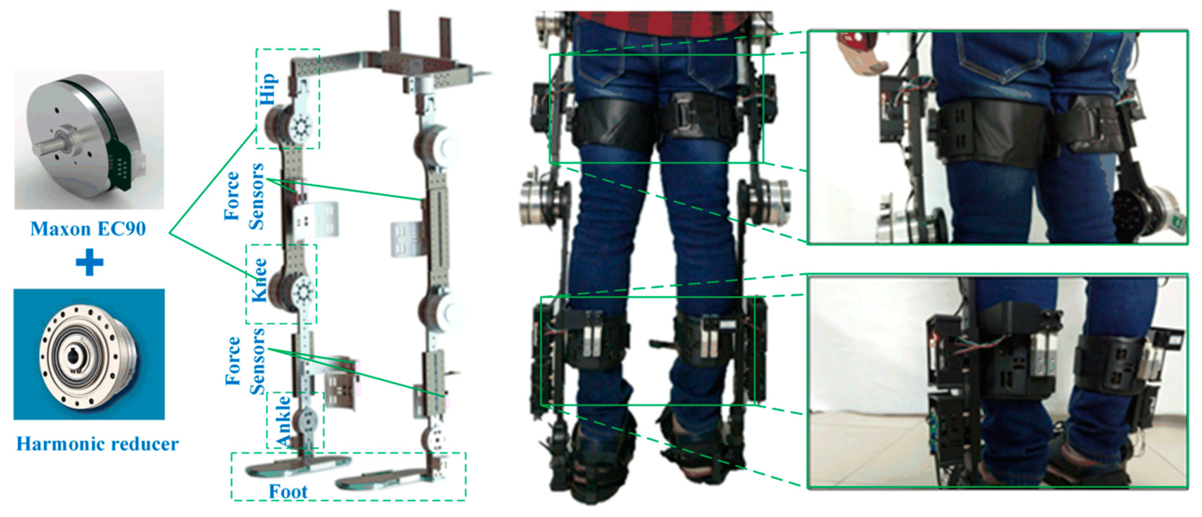
1. Introduction
With increase in the global aging population, the number of patients with lower limb dyskinesia caused by diseases such as locomotive syndrome and sarcopenia is on the rise. According to research on medical theory and clinical experience, patients with locomotive syndrome and sarcopenia can prevent muscle atrophy and promote muscle functional recovery through high-intensity and repetitive exercise rehabilitation training [
1]. The lower limb rehabilitation exoskeleton (LLRE) robot is a human mechatronic system that integrates the robot and the wearer [
2]. By simulating normal human walking gait, it helps patients with lower limb motor dysfunction to exercise lower limb muscles and restore function [
3,
4]. In the study of LLRE, especially in control strategies and methods, researchers focus more on patients’ active participation in rehabilitation training [
5] and safety and comfort during rehabilitation training [
6].
For patients with lower limb paralysis, because the lower limb muscles do not actively contract [
7], in order to prevent lower limb muscle atrophy, the affected limb is passively driven by the exoskeleton, and the purpose of limb movement recovery is gradually achieved under passive rehabilitation training. In the existing literature, various LLREs that can be used for passive rehabilitation training have been developed and studied, such as MINDWALKER [
8] (University of Twente, Enschede, Netherlands), ATLAS [
9] (Centre for Automation and Robotics, La Poveda, Madrid, Spain), ReWalk [
10] (Rewalk Robotics, Marlborough, MA, USA), EKSO [
11] (Ekso Bionics, Richmond, VA, USA), Twin [
12] (IIT, Via Morego, Genova, Italy), etc. The control system of the above LLREs is essentially a passive position control system, because active participation of the wearer is not considered in the system. However, for patients with lower limb dysfunction, such as locomotive syndrome and sarcopenia, they still have a certain amount of muscle strength retained in their affected limbs [
13]. The patient’s active movement intention should be taken into consideration in rehabilitation training to improve active participation, thereby improving the effect of rehabilitation training [
14].
In the study of LLRE control strategies for the rehabilitation training of patients with residual muscle strength in their affected limbs, two main issues need attention. The first is how exoskeleton adaptively adjusts training tasks according to the condition of different patients’ affected lower limbs [
15,
16,
17]. The second is how to optimize the exoskeleton control strategy based on the active muscle force of the patients’ lower limbs, so that they can participate in rehabilitation training as much as possible to achieve maximum exercise of the muscles. The LLRE robot can directly interact with patients’ lower limbs [
18,
19]. On one hand, LLRE needs to provide power for lower limbs to follow the standard gait trajectory [
20]. On the other hand, it is necessary to ensure that the power provided can be adaptively adjusted according to the patient’s active muscle force to ensure active participation [
21].
In order to increase a patient’s active participation in exoskeleton-assisted rehabilitation training, it is necessary to control the exoskeleton robot to track the movement of the lower limb as per the patient’s active motion intention [
22,
23]. Impedance controller or admittance controller have been widely used in exoskeleton control due to their characteristics of human and robot physical interaction [
24,
25]. The impedance controller calculates the force exerted by the robot to achieve the specified displacement. Admittance control is based on the impedance control and uses an external force loop and an internal position loop to form the entire controller [
26]. Aydin et al. [
27] adopted an admittance controller to convert the interaction force between the human body and the exoskeleton into the expected trajectory of the exoskeleton, so as to recognize and track the operator’s intention. Aiming at the safety of robot-assisted interactive motion of the affected limb, Pan et al. [
28,
29] proposed an exoskeleton impedance control method based on safety monitoring, but the active muscle force of the patient’s limbs was not considered in human-robot interaction. Aguirre-ollinger et al. [
30] analyzed the stability conditions of admittance control of a single-degree-of-freedom exoskeleton swinging leg, and believed that admittance control can improve the compliance of the exoskeleton leg [
31]. Wang et al. [
32] applied admittance control to the active training stage of patient rehabilitation, and adjusted the admittance parameters to meet the different needs for strength and speed during training. Morbi et al. [
33] proposed that non-linear admittance control can promote a safer human-computer interaction in haptic devices. The above research results show that admittance control can effectively recognize the movement intention of exoskeleton wearers, and the control system using admittance control has a simple structure and is easy to implement. However, the above studies on exoskeleton admittance control have adopted fixed admittance parameters to control exoskeleton, which has limitations in the application of LLREs. On the one hand, when the patient has a negative intention, that is, the direction of the active torque of the lower limb joint is opposite to the preset motion trajectory speed, if the admittance parameters of the admittance controller is too large, that is, the exoskeleton stiffness is too large, the physical interaction between the patient’s lower limbs and exoskeleton will increase, bringing discomfort and safety risks to the patient. On the other hand, when the patient has a positive intention, that is, the direction of the active torque of the lower limb joint is the same as the preset movement trajectory speed, if the admittance parameters of the admittance controller is too small, that is, the stiffness of the exoskeleton is too small, the intensity of the patient’s rehabilitation training will decrease, leading to a decrease in active participation and thus a reduction in the rehabilitation effect.
For the rehabilitation training of patients with dyskinesia that have residual muscle strength in the affected limb, the passive position control scheme for LLRE ignores the active participation of patients in rehabilitation training and cannot fully meet the rehabilitation training needs of such kind of patients. Moreover, admittance control with fixed admittance parameters for LLRE ignores the patients’ positive and negative intentions in rehabilitation training, and affects the comfort, safety and active participation of patients in rehabilitation training. Therefore, this paper described a novel ASMVA control strategy for LLRE, which can estimate the patients’ movement intention based on the human-exoskeleton interaction force, and can actively adjust the intensity of rehabilitation training according to the patients’ movement intention, which can effectively help patients exercise muscle to restore the muscle strength of the lower limbs, and solve the problems of passive rehabilitation training with fixed trajectory and admittance control with fixed admittance parameters.
3. Methods
3.1. Human-Exoskeleton Coupling Dynamics Modeling
The exoskeleton robot has two unique characteristics, namely physical and cognitive interaction between human limbs and the exoskeleton. The physical interaction is a force interaction, and the exoskeleton can enhance the strength of human limbs. The cognitive interaction means that the wearer can feel that he is controlling the exoskeleton. At present, in the dynamic analysis of exoskeleton system, researchers usually only pay attention to the dynamic characteristics of the exoskeleton system itself, or take the exoskeleton system and human limb as a rigid connection for dynamic analysis, and ignore the physical interaction between the exoskeleton and the human limb. It is of great significance in the study of adaptive sliding mode variable admittance control of exoskeleton robot based on human-exoskeleton physical interaction to establish a coupling dynamic model of exoskeleton and human limb.
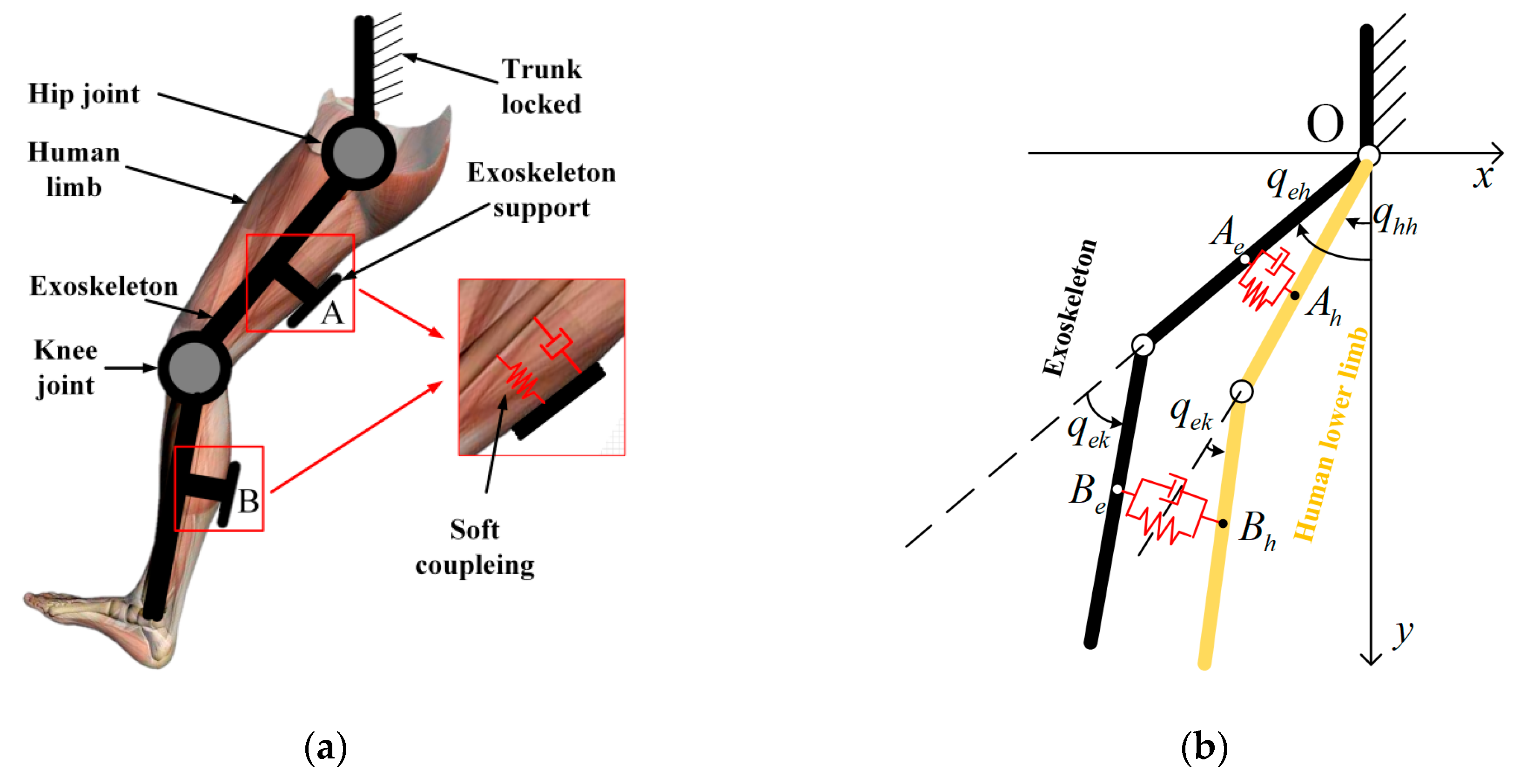
In this work, the 2-DOF connecting-rod model is adopted in coupling dynamics analysis of the exoskeleton and human limb. The 2-DOF connecting-rod model contains a trunk, thigh, and shank with the trunk locked, so the swing process is essentially the rotation of the thigh around the hip joint and the shank around the knee joint. Because the human leg is attached to the exoskeleton support, the muscle and fat in the human leg will produce soft coupling between the exoskeleton and the skeleton, which allows relative movement of the human leg skeleton and the exoskeleton. As shown in
Figure 4a, this soft coupling can be modeled using linear spring with coefficient
and linear damper with coefficient
. The simplified model is shown in
Figure 4b.
According to the Euler-Lagrange equations, the dynamic model equation of a human leg can be described by:
where
denotes the state vector of human joint angle,
denotes the state vector of human joint angular velocity,
denotes the state vector of human joint angular acceleration.
is the state vector of torque generated by human hip joint and knee joint.
is the inertia matrix of single human lower limb, which is a symmetric positive definite matrix.
is the coriolis force vector.
denotes the gravitational torque vector.
Similarly, the dynamic model equation of a 2-DOF exoskeleton is given as:
where
denotes the state vector of 2-DOF exoskeleton joint angle,
denotes the state vector of 2-DOF exoskeleton joint angular velocity,
denotes the state vector of 2-DOF exoskeleton joint angular acceleration.
is the vector of torque generated by the exoskeleton.
is the inertia matrix of exoskeleton, which is a symmetric positive definite matrix.
is the coriolis force vector of the exoskeleton.
denotes the gravitational torque vector of the exoskeleton.
There is a force interaction between the exoskeleton and the human lower limb. For patients with residual muscle strength in the lower limbs, their own muscle strength cannot help them walk normally, so the interaction force is a promotion for patients, but for the exoskeleton, the interaction force is a resistance, so the dynamic equation of human-exoskeleton coupling system can be given as:
where
,
are the Jacobian matrices of the human lower limb, and
,
are the Jacobian matrices of the 2-DOF exoskeleton.
and
denote the coupling terms of the human lower limb dynamics equation and 2-DOF exoskeleton dynamics equation, and their physical meanings are the interaction force of human limb and exoskeleton at the thigh and shank, respectively, and are given by:
where
,
are coordinates of exoskeleton contact point
and bone contact point
at the connection of the exoskeleton and the thigh.
,
are coordinates of exoskeleton contact point
and bone contact point
at the connection of the exoskeleton and the shank. The coordinates of four points and their first derivative can be expressed as follows:
where
and
denote lengths of the thigh and the shank of the human lower limb,
and
represent lengths of the thigh and the shank of the exoskeleton. It is assumed that the rotation axes of the first joint of exoskeleton and the human hip joint are coincident. Then
and
denote distance from the human hip joint and the knee joint to point
and point
,
and
represent distance from the first joint and the second joint of exoskeleton to point
and point
.
According to
Figure 5, we can see that if the torque generated by the human is zero, then the human lower limb is driven entirely by the exoskeleton, and
is the only driving force of the human lower limb, which we can call standard interaction torque
. However, if the human lower limb retains some muscle strength, it means that the torque generated by the human is not zero. As a result,
and
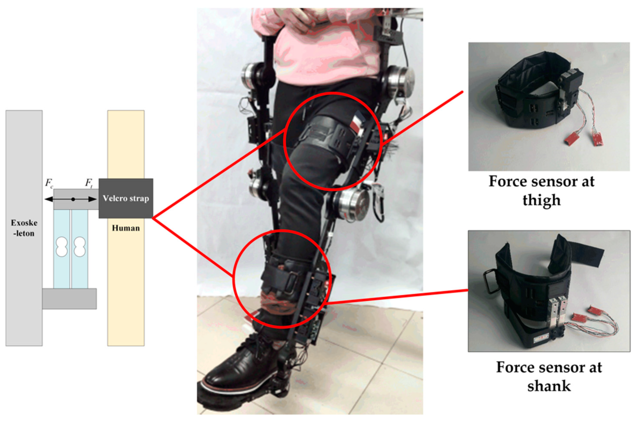
are the driving forces of the human lower limb. Therefore, assuming that the trajectory of the exoskeleton joint is the same in both cases, if the torque generated by the human joint follows the rotation direction of the exoskeleton joint, the interaction torque between the human lower limb and the exoskeleton will be reduced, but if the torque generated by human joint does not follow the rotation direction of the exoskeleton joint, the interaction torque between the human lower limb and the exoskeleton will be increased. As a result, from the change of interaction torque, the torque generated by the human joint can be obtained, which shows motion intention. However, there is no good sensor measuring torque generated by human joint directly, but the interaction force between human lower limbs and exoskeleton can be measured easily by using a force sensor described above. According to interaction force, we can estimate the interaction torque between the human lower limbs and the exoskeleton. Finally, we can estimate the voluntary torque generated by the human joint by comparing the interactive torque with standard interactive torque. As shown in the equations below:
where
is the standard interactive torque,
is the estimating value of voluntary torque generated only by the wearer himself,
can be obtained by standard interactive torque
subtracting the actual measured interactive torque
.
3.2. Variable Admittance Controller Design
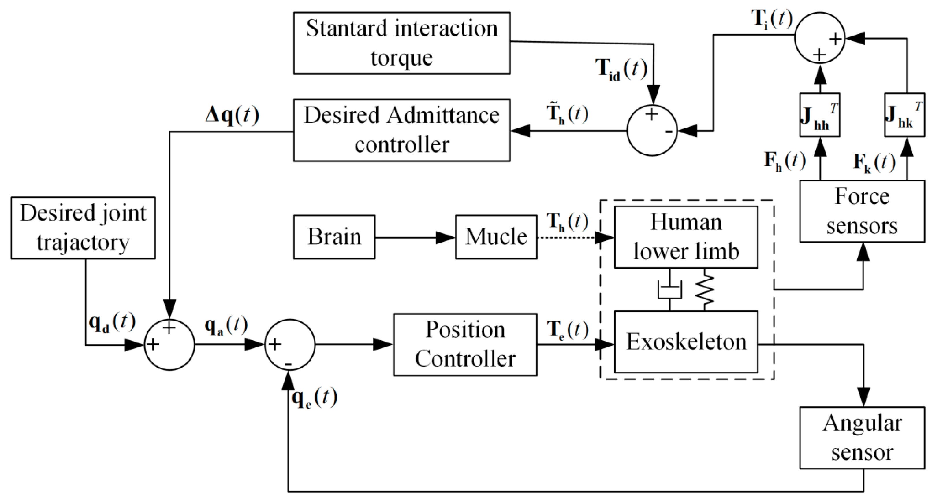
In humans, the brain is the controller, and the muscle is the actuator. In normal walking, the main problem of patients with lower muscle strength is that their muscles cannot provide the required torque to make them walk normally. In other words, when the human leg is in a swing phase, the torque provided by the muscles is not enough to make the human leg swing to the desired angle. Therefore, an admittance controller is proposed, which can judge human motion intention according to the interaction force between the human and the exoskeleton, and control the human exoskeleton system to make the human leg swing to the desired angle. The admittance control structure of the human-exoskeleton coupling system is shown in
Figure 6. It is worth noting that the movement is still determined by the wearer, and the admittance controller adjusts the reference rehabilitation training trajectory to provide appropriate assistance according to the wearer’s motion intention.
Admittance controller is the reciprocal variant of the impedance controller, whose performance depends on the accuracy of the force sensor and the position sensor. Compared with impedance control, admittance control is usually easier to implement in hardware. According to the definition of impedance, the desired impedance model of interaction between the human lower limbs and the exoskeleton can be designed as:
where
,
, and
are desired rotary inertia matrix, desired rotary damping matrix and desired rotary stiffness matrix respectively;
and
are desired move trajectory vector and desired control trajectory vector of the exoskeleton for rehabilitation of human lower limb in joint space, so
is the correction of the desired trajectory;
is the estimated voluntary torque generated by the human joint, which can be obtained by the above method.
Because the patient’s own muscle strength is small, the patient’s movement is relatively slow in the rehabilitation training. Thus, the acceleration term in the impedance model could be ignored; by only considering the rotation damping coefficient and rotation stiffness coefficient, the following impedance model could be obtained:
In the frequency domain space of the control system of exoskeleton, Equation (13) can be rephrased as:
In the process of rehabilitation training, the rotational stiffness and damping of the human lower limb joint will change according to the voluntary torque of the human; therefore, the parameters of the admittance controller also need to be changed according to changes in human voluntary torque. Based on the voluntary torque of the wearer’s lower limb joint, the admittance parameters are changed. When the voluntary torque of the human joint is large, the parameters of the admittance controller should be appropriately increased to increase the training intensity and active participation of the wearer. When the voluntary torque of the human joint is small, the parameters of the admittance controller should be appropriately reduced to make it easier for the wearer to move the exoskeleton.
In rehabilitation training, the patients’ intention of movement can be divided into two types: one is that the lower limbs voluntarily follow the desired trajectory, the other is that the lower limbs resist following the desired trajectory, which can be shown as follows for the single joint:
where
and
are actively used damping and stiffness, respectively,
and
are base damping for positive moment and negative movement, respectively,
and
are base stiffness for positive movement and negative movement, respectively. The parameters
and
are tuned manually to control the rate of change of
, and the parameters
and
are tuned manually to control the rate of change of
.
The variable admittance controller, established based on the voluntary torque generated by the human lower limb, can adaptively adjust the admittance parameters according to the patients’ movement intention, and modify the desired trajectory to obtain the control reference trajectory in joint space, which can not only ensure the active participation of the patients, but also reduce interaction to ensure training safety and comfort.
3.3. Design of Adaptive Sliding Mode Controller
When patients wear the exoskeleton for rehabilitation training, the lower limbs may have involuntary shaking, and the exoskeleton robot may also have uncertain vibration, which will cause disturbance to the exoskeleton robot system and affect the accuracy of the tracking reference control trajectory of the exoskeleton robot. Therefore, in this paper, a sliding mode control method based on RBF neural network is proposed for position control of the exoskeleton. This algorithm uses sliding mode control to enhance the robustness of the control system against uncertain disturbances, and RBF neural network to fit the system model, which is difficult to accurately model to reduce chattering of the sliding mode controller.
Considering the modeling error and uncertainty disturbance of the human-machine coupling dynamic model, the dynamic model of exoskeleton robot can be rewritten as:
where
is the exoskeleton control torque, and
is the uncertainty caused by modeling error and system disturbance.
The goal of designing the sliding mode controller is to ensure that the actual trajectory
of exoskeleton can track the command trajectory
. It assumed that the trajectory tracking error is
, where
. The sliding surface is designed as follows:
where
is a positive definite matrix,
is the slope of the sliding surface. Then:
where
is the uncertainty term in the exoskeleton dynamics model. In engineering applications, the uncertain term
of the model is unknown, so it is necessary to approximate the uncertain term
. The basic idea of the RBF neural network is to use the radial basis function as the basis of the hidden layer neurons to form the hidden layer space. The hidden layer transforms the input data of the low-dimensional mode into the high-dimensional space, which makes the linear indivisible problem in the low-dimensional space linearly separable in the high-dimensional space. The RBF neural network is simple in structure, simple in training, and fast in convergence, and can approach any nonlinear function; therefore, the RBF neural network is used to approximate the uncertain term
.
Taking
as the input of the RBF neural network, and taking Gaussian function as a membership function, the RBF neural network algorithm can be denoted as follows:
where
, and
is the number of neurons in the hidden layer of the RBF neural network,
and
are the center value and standardization constant of Gaussian function of the i-th neuron in the hidden layer of the RBF neural network, respectively,
is the connection weight matrix from the hidden layer to the output layer,
is the approximation error.
Due to the existence of approximation error, the actual output of the neural network can be set as:
where
is the actual weight matrix of the RBF neural network when approaching
,
is the hidden layer basis vector of the RBF neural network.
The sliding mode control law is designed as follows:
where
is the control parameter of the sliding mode controller,
is the designed sliding surface,
is the robust term of the controller to overcome system disturbance.
Considering the approximation error
of the neural network and the disturbance term
in the actual exoskeleton control, the robust term
is designed as:
where
is the maximum permissible error of RBF neural network approximation,
is the maximum disturbance of the system.
3.4. Proof of System Stability
The Lyapunov function of the control system is defined as follows:
where
is a positive definite matrix,
is the weight error matrix of the RBF neural network in approximation,
is to trace matrix
, whose result is a constant value.
The first derivative of the Lyapunov function shown in Equation (26) is obtained as follows:
Combining Equation (20), Equation (22), and Equation (24):
Then . According to Lyapunov’s stability discrimination theorem, when , and , . Because is a negative definite, it is asymptotically stable at the origin, and because , and is uniformly bounded by Lyapunov stability theory. In addition, because , is uniformly bounded, therefore, according to Barbalat’s lemma, when , , it is , thus and , which proves that the control system is stable.
3.5. Experimental Design and Implementation
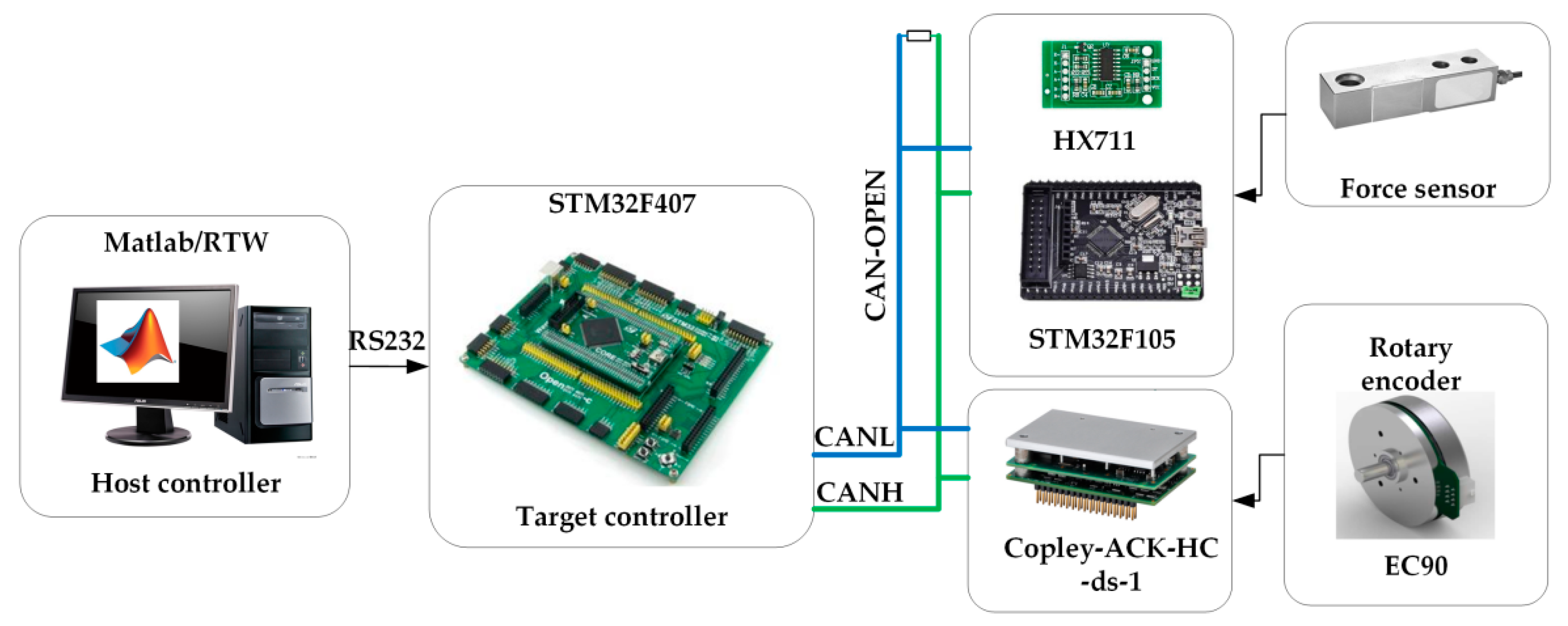
In order to verify the effectiveness of the ASMVA controller for the LLRE robot, the human-exoskeleton interaction measurement experiment and the track tracking experiments under different admittance conditions based on the exoskeleton platform were carried out in this paper, as shown in
Figure 7. In these experiments, the subject’s left leg was connected to the exoskeleton through a Velcro strap at the thigh and shank of the exoskeleton, and the exoskeleton was fixed on the base made of aluminum profiles by screws to avoid falling and shaking of the exoskeleton. During these experiments, the actual movement track of the exoskeleton joint was measured in real time by the rotary encoder, and the interaction torque of the knee joint was measured in real time by the interaction force sensor installed between the shank of subject and the shank of exoskeleton. The motor drivers were set as torque control mode, which provided auxiliary force for the lower limbs of the human body according to the control algorithm and the feedback sensor signal. Three healthy subjects with different body measurement parameters (H1: male, 24 years old, weight/60 kg, height/1.70 m; H2: male, 23 years old weight/65 kg, height/1.75 m, H3: female, 25 years old, weight/51 kg, height/1.60 m) participated in the study and provided consent before the experiment. This study was approved by the biomedical ethics committee of the medical department of Xi’an Jiaotong University.
3.5.1. Human-Exoskeleton Interaction Measurement Experiment
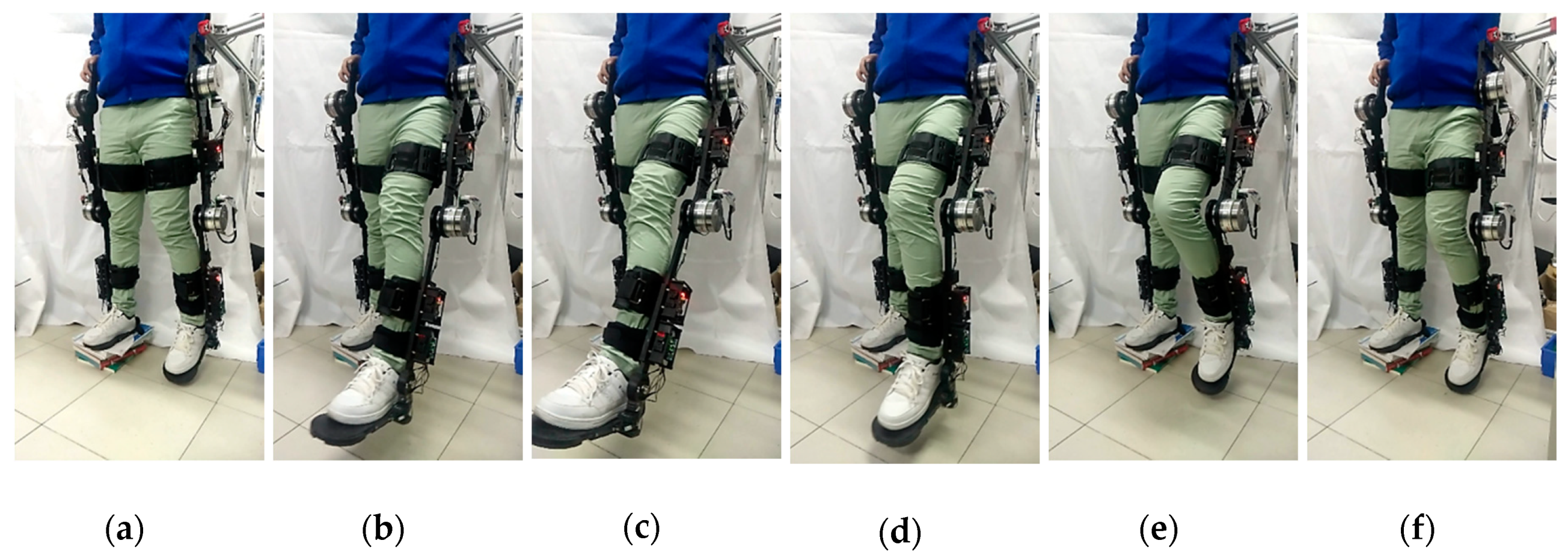
The purpose of the human-exoskeleton interaction measurement experiment was to obtain the relationship between the angular displacement and the standard interaction torque of the knee-joint. This experiment was based on the subject’s knee-joint flexion movement, which is shown in
Figure 8. During this experiment, the left leg of the subject did not generate any active force, and the exoskeleton adopted position mode control, that is, the joint of the exoskeleton rotated according to the preset motion track under the servo drive system. Firstly, the hip-joint of exoskeleton rotated by 35 degrees in flexion, then the hip-joint of exoskeleton locked up, and the knee-joint of the exoskeleton extended and flexed two times in a reciprocating motion; the joint rotation amplitude was 60 degrees. Finally, the hip-joint of the exoskeleton was rotated by 35 degrees in flexion motion to restore its vertical state.
3.5.2. Track Tracking Experiments Under Different Admittance Conditions
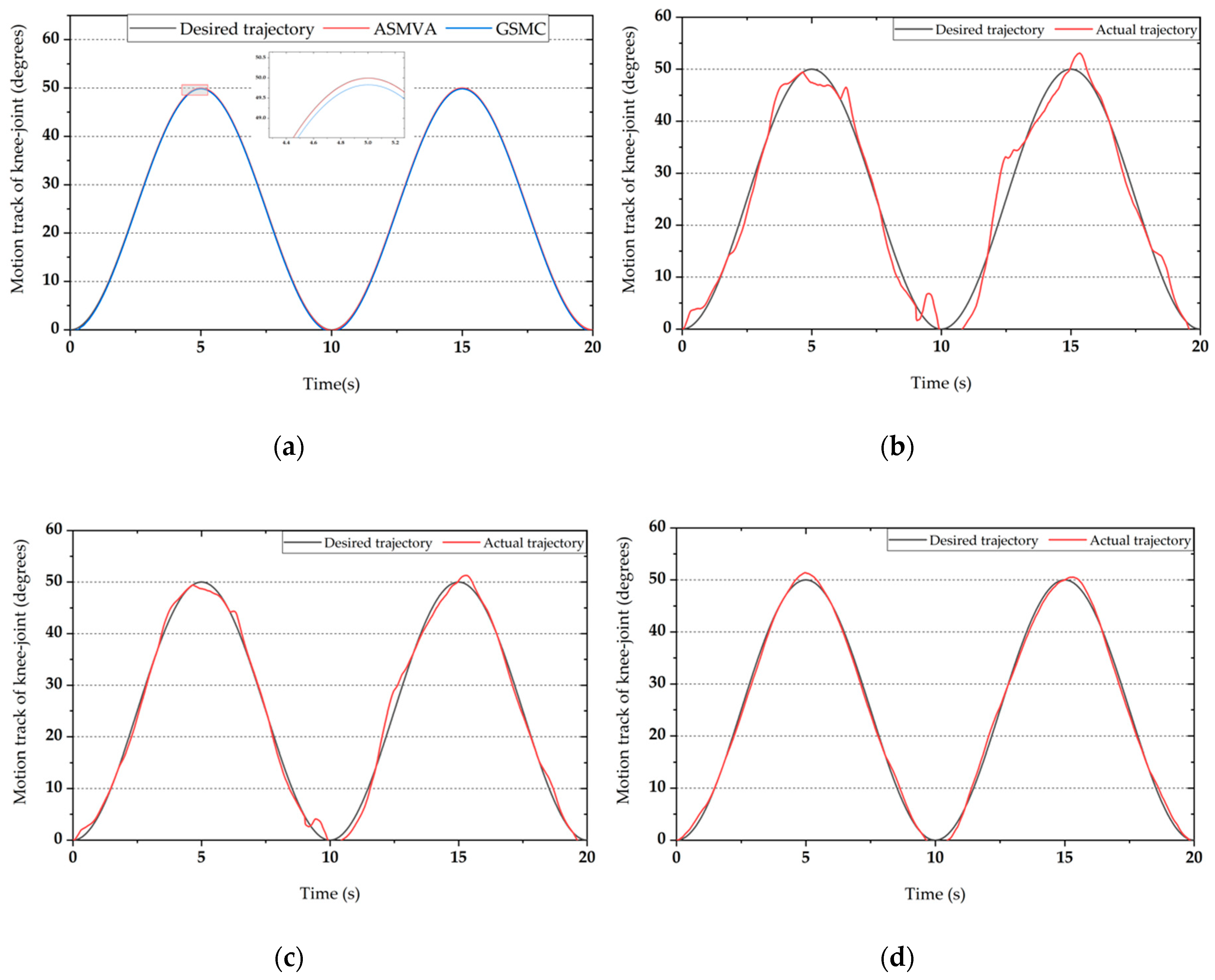
The track tracking experiments under different admittance conditions mainly includes three sub-experiments, which are track tracking experiment with no admittance, track tracking experiment with fixed admittance, and track tracking experiment with variable admittance. Track tracking experiment with no admittance was carried out to verify the position control performance of the proposed ASMVA controller. Through the track tracking experiment with fixed admittance, the influence of different fixed admittance parameters on track tracking was analyzed. Track tracking experiment with variable admittance was carried out to verify that the proposed ASMVA controller could adjust admittance parameters according to patients’ movement intention in training.
According to the overall block diagram of the control strategy shown in
Figure 6, the inner loop ASMC (adaptive sliding mode controller) controller is responsible for accurate tracking of the preset trajectory of the knee-joint adjusted by the admittance controller. In fact, if the admittance parameters are all set to infinity, the ASMVA controller can be transformed into a position controller to track the predefined training track. Therefore, this track tracking experiment with no admittance was carried out to prove the control accuracy of the inner loop ASMC controller. The initial state of track tracking experiment was that the hip joint of exoskeleton drove the subject’s leg to rotate 35 degrees, and then the hip joint was locked. During this experiment, the knee joint track was preset as a sine wave track with frequency of 0.1 Hz, peak amplitude of 50 degrees and phase of
. The time required for each experiment was 20 s, that was, the subject’s shank swung two cycles along the preset sine wave track driven by the exoskeleton. In order to ensure control accuracy and system stability, the parameters of the GSMC (general sliding mode controller) algorithm were tested many times and modulated optimally. The recommended control parameters for ASMVA controller were set to
,
,
,
,
,
,
,
. The recommended configurations of the RBF neural network were: the number of hidden layer nodes was 7,
,
.
The purpose of the passive training mode with no admittance is to ensure the accuracy of repeated track tracking during rehabilitation training, and it is suitable for patients without any active muscle strength. However, if the patient restores part of muscle strength, the introduction of admittance control into passive training mode can improve the flexibility of human-exoskeleton interaction and ensure the comfort of the patient in the training process. In order to verify the influence of the ASMVA controller on track tracking under different fixed admittance parameters, subject H1 (male, 24 years old, weight/60 kg, height/1.70 m) was required to wear the exoskeleton for a track tracking experiment under three different admittance controller configurations of large admittance, medium admittance, and small admittance. During this experiment, the left leg of the subject was required to generate some active force, and the desired control trajectory was the same as that of track tracking experiment under infinite admittance condition; three different admittance controller configurations of this experiment are shown in
Table 1.
There are two situations in actual rehabilitation training of patients with residual muscle strength. One is that the direction of the knee joint active torque is the same as the speed direction of the desired training track, which can be regarded as the patient’s positive movement intention. The other is that the direction of the knee joint active torque is opposite to the speed direction of the desired training track, which can be regarded as the patient’s negative movement intention. In order to verify the performance of the ASMVA controller on the recognition of patients’ movement intention and track tracking under the condition of variable admittance, subject H1 (male, 24 years old, weight/60 kg, height/1.70 m) was required to wear an exoskeleton for track tracking experiment under the condition of variable admittance. During this experiment, the left leg of the subject was required to generate some active force, and the desired control trajectory was the same as that of the track tracking experiment under infinite admittance condition; the variable admittance controller configurations of this experiment are shown in
Table 2.
5. Discussion
This research shows that the ASMVA controller is more suitable for patients with residual muscle strength of lower limbs than the fixed parameter admittance controller, because the ASMVA controller can estimate the patient’s active joint torque according to the human-exoskeleton interaction force, so as to obtain the patient’s movement intention. It can not only increase the training intensity according to the active muscle strength of the patient during the patient’s active movement intention to increase the patient’s active participation, but also increase the trajectory adjustment amount during the patient’s negative movement intention to ensure patient’s safety. The present study differs from other studies in two main aspects. Firstly, this paper proposes an innovative method to estimate the active joint torque of the exoskeleton wearer based on the standard human-exoskeleton interaction torque. Secondly, the ASMVA controller is introduced into the control of the lower limb rehabilitation exoskeleton robot, which realizes the exoskeleton admittance control with the change of admittance parameters.
Unlike the previous research [
34,
35], in our study, the input of admittance controller is the active joint torque of patients, rather than the interaction between the exoskeleton and patients’ limbs. Ee used the variable admittance controller, which can adaptively adjust the admittance parameters according to the patient’s movement intention during rehabilitation training. The biggest advantage of our research is that our study took into account the patients’ positive and negative movement intentions during rehabilitation training, which realizes the control of the exoskeleton based on the patient’s movement intention, so as to improve efficiency of the training. When the patient has positive intention in rehabilitation training, increasing admittance parameters means increasing the stiffness and damping of the system; then, the intensity of rehabilitation training is increased to ensure participation of the patients. When the patient has negative intention in rehabilitation training, decreasing admittance parameters means decrease the stiffness and damping of the system, which can ensure the safety and comfort of the patient.
Clinical research has confirmed that the lack of muscle strength in patients with dyskinesia is an important factor affecting the recovery of limb function [
36], and the lack of muscle strength has a direct responsibility in causing sports reinjury [
37]. Therefore, in rehabilitation training, it is very important to improve muscle strength of the lower limbs of patients. Research by Krishnan et al. [
38] confirmed that improving the participation of patients in the process of rehabilitation training is very helpful in improving the muscle strength of patients. As an example, for patients with locomotive syndrome and sarcopenia, their affected limbs retain a certain of muscle strength. At this time, the ASMVA controller can be applied to the rehabilitation training of this kind of patients, because the ASMVA controller can estimate the active joint torque of the lower limbs of the patients, so as to judge the movement intention of the patients to adjust the rehabilitation training trajectory adaptively. The ASMVA controller can adaptively change the intensity of rehabilitation training by judging the positive movement intention of patients and the strength of muscles, so as to ensure the active participation of patients during the rehabilitation training. Besides, the ASMVA also provides a security mechanism, that is, when the controller detects that the direction of the patient’s active joint torque is not the same as that of exoskeleton joint velocity, it reduces the admittance parameters to decrease the system stiffness, thus reducing the interaction between the patient and the exoskeleton, and ensuring the safety of patients during the rehabilitation training.
Finally, it should be noted that the study had one limitation. The basic stiffness and damping of the variable admittance controller need to be adjusted according to the degree of symptoms or recovery degree of muscle strength of lower limb in dyskinesia patients with residual muscle strength. Therefore, future work will further improve the robot-assisted patient training evaluation system based on this research, and provide the basis for optimizing system control parameters and rehabilitation training strategies.
