Abstract
The effect of using a pulse shaper technique, such as rounding a striker or applying a pulse shaper on the signals recorded with the split Hopkinson pressure bar (SHPB) technique, when the striker and the input bar are in an imperfect position, was investigated. Two of the most common cases have been analyzed: an offset of the symmetry axes of the striker and the input bar; and an inclination angle between the striker and the input bar. LS-Dyna software was used to examine this problem numerically. The inclination angle imperfection has a significant impact on signal disturbances, whereas the use of a rounded striker significantly affects the limitation of the vibration flexural modes. In all considered cases, a slight imperfection causes a reduction in the high-frequency Pochhammer–Chree oscillations.
1. Introduction
The split Hopkinson pressure bar (SHPB) technique is currently the most popular measurement technique for the determination of material properties at a high-strain rate [1].
The SHPB method is applicable when a specimen is deformed nearly uniformly at a constant strain rate under dynamically equilibrated stresses, and the propagation of the elastic waves through the input and output bars is described by one-dimensional wave theory [1]. The nearly uniform sample deformation at a constant strain rate under dynamically equilibrated stresses is realized by: a pulse-shaping technique [2,3], the conical (tapered) strikers method [4,5,6], or a three-bar technique with a dummy specimen [7]. The pulse-shaping technique and the three-bar technique with a dummy specimen usually cause minor changes in the incident wave, which are limited to increasing the rise and the fall time [8,9], and damping the Pochhammer–Chree high-frequency oscillations [10,11]. However, ensuring the system behavior in accordance with one-dimensional wave theory is possible only by a proper axisymmetric arrangement of the experimental set-up. The non-axisymmetric position of the bars and the striker in the SHPB arrangement results in disturbances in the useful signals that are propagating in the bars and measured by strain gauges.
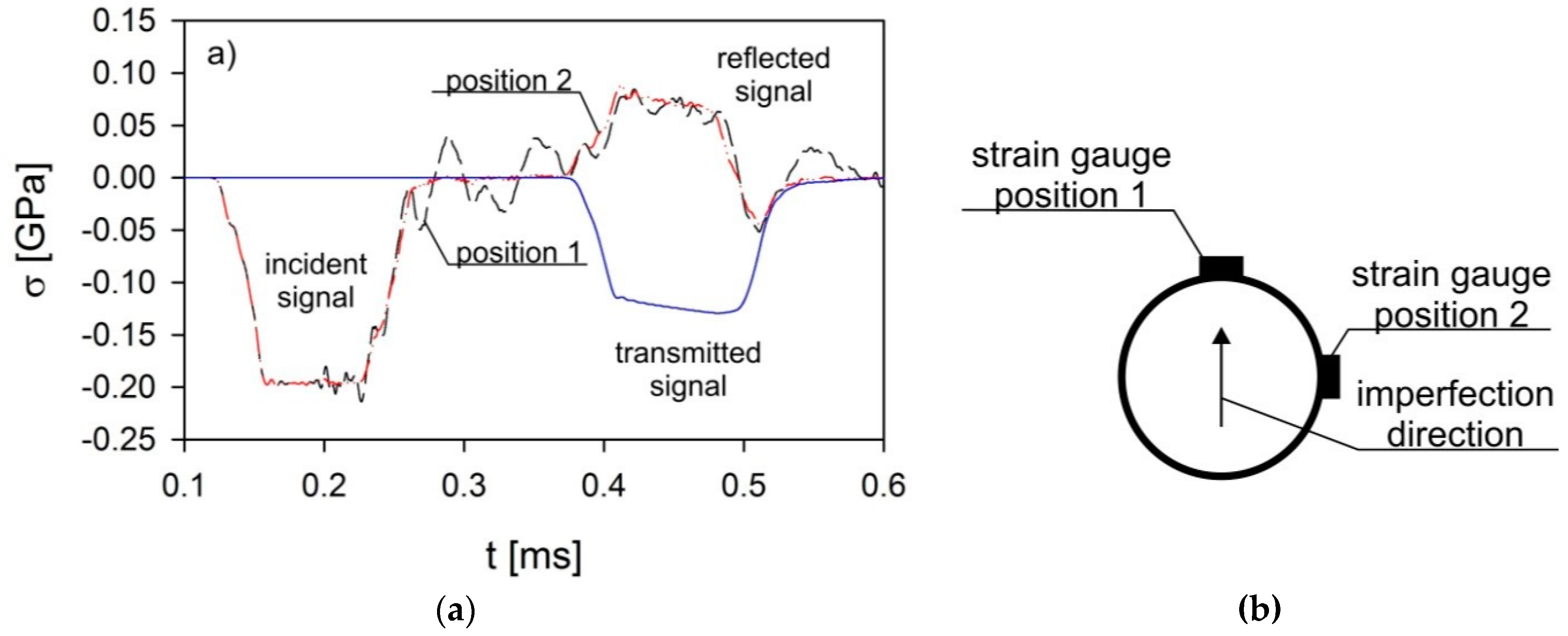
Based on numerical analyses, Kariem et al. showed that the resulting signal disturbances in the Hopkinson split bar method are caused by flexural modes of vibration from an imperfect condition in the SHPB experimental set-up [12]. The flexural modes of vibration create a three-dimensional pulse propagation that is inconsistent with the previously described requirements of the SHPB method. The results of the numerical investigations were confirmed experimentally by Wu et al. using the photonic Doppler velocimetry (PDV) technique [13]. They suggest using a quarter-Wheatstone bridge to measure deformations in the SHPB technique, which allows for easy detection of signal disorders. However, in practice [14], it was shown that the disturbance of the measurement signals caused by imperfections in the SHPB arrangement is dependent on the relative position of the imperfection (signal disruption) and strain gauges with respect to the symmetry axis of the bars and the striker. Disorder of the measurement signals is the highest when a relative position of these components coincides (Figure 1 strain gauge position 1), while the disorder of the signals is the lowest when the relative position differs by 90° (Figure 1, strain gauge position 2). The influence of the imperfection is particularly visible in the reflected signal. To evaluate the proper axisymmetric arrangement of the experimental set-up, at least two gauges should be used in a quarter-Wheatstone arrangement placed on the bar at an angle of 90° to each.
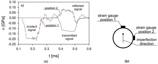
Figure 1.
Disturbances of wave signals (a) depending on the relative position of the pulse shaper and the strain gauges (b) [14].
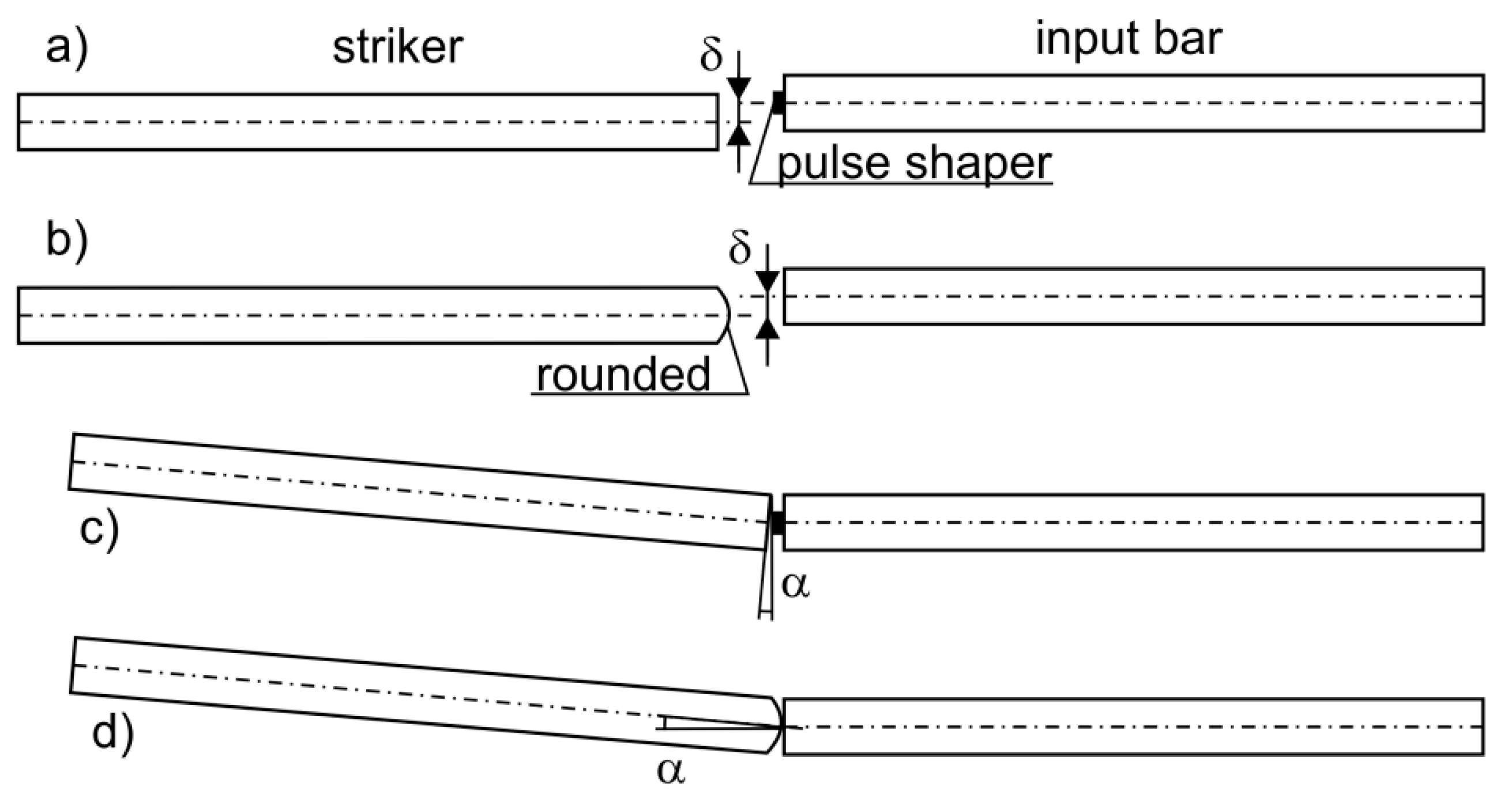
The goal of this work is to demonstrate the effect of using a pulse shaper technique, such as rounding a striker or applying a pulse shaper on the signals recorded in the SHPB technique, when the striker and the input bar are in an imperfect position. Two of the most common cases, which can only be limited but not eliminated, have been analyzed. The first case consists of an offset of the symmetry axes of the striker and the input bar by a value of δ (Figure 2a). In the second case, the striker hits the input bar at an inclination angle, α (Figure 2b). To achieve the goal of this work, the author carried out numerical analyses using the commercial finite element method (FEM) software LS-Dyna [15].
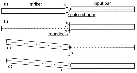
Figure 2.
Striker and bar misalignment; neutral axis offset δ (a), striker hitting the input bar at inclination angle α (b), (a), and (c) with use of the pulse shaper; (b,d)—with rounded striker.
2. Split Hopkinson Pressure Bar Theory
The SHPB set-up usually consists of a striker and two long bars, called an input bar and an output bar, with the same diameter and material (typically a high-strength material such as maraging steel) (Figure 3). A material sample is placed between the bars, and it is loaded by a stress impulse generated by the striker impact on the front surface of the input bar. This generates a trapezoidal stress impulse (incident wave), which travels through the impacted bar. When the elastic wave reaches the specimen, due to the mismatch of mechanical impedances between the bar and the specimen material, part of the incident wave is reflected back (reflected wave), and the rest of the incident wave is transmitted through the specimen. It compresses the specimen at high rates, and the rest of the wave travels to the output bar as a transmitted wave. The incident and the reflected signals are recorded by the strain gauges, which are fastened on the input bar, and the transmitted signals are recorded by the strain gauges located on the output bar. The information about the dynamic behavior of the sample is included in the incident, reflected, and transmitted signals. Time-resolved engineering stress, strain rate, and strain in the specimen are defined by the following equations [1]:
where As and Ls are the initial cross-section area and length of the specimen, respectively; c0, E, and A are the sound velocity, Young’s modulus, and bar initial cross-section, respectively; ε(t) is the strain signal sensed by strain gauges; and the I, R, and T subscripts denote incident, reflected, and transmitted pulses, respectively.

Figure 3.
Split Hopkinson pressure bar (SHPB) set-up with strain gauges position and recorded signals.
The strain acceleration, which is the effect of a non-constant strain rate, can produce additional axial stress and radial stress in the specimen [16,17,18,19]. The inertia and friction effects in the form of overstress are given by [14]:
where ds and ls are the current diameter and length of the specimen, respectively, μ is the friction coefficient, and σexp is the measured specimen stress. According to Equation (4), an assurance of a constant strain rate in the measuring range, the choice of the initial sample length and diameter leading to , and lubrication contacts between the specimen and bars cause the overstress to reach a minimum. Davis and Hunter’s study shows that a sample length-to-diameter ratio should be [20].
3. Methodology of Numerical Investigations
To determine the effect of imperfections, shown in Figure 2, on the signal disturbances measured in SHPB experiments when a pulse-shaping technique was used, a 3D finite element model was built. A finite element model of the SHPB arrangement used in the numerical analyses corresponded to the experimental set-up presented in Paper 14. The model contains not only all important components of the arrangement (Figure 4), i.e., bars, sample, striker, but also a pulse shaper, slide bearings, and a barrel.

Figure 4.
A schematic diagram of the SHPB set-up used in the numerical analysis.
The bars and the striker, which work within an elastic limit, are described by eight-node solid elements with single-point integration. Through numerical experiments, the size of the finite elements describing the bars and the striker was chosen such that they allow a very good mapping of not only the amplitude and duration of the propagating pulses but also the rise and fall time of the pulses and the Pochhammer–Chree high-frequency oscillations. The number of elements in the cross-section was 316, and the average dimension of the elements was 0.3 mm. In total, each of the bars is described by more than 2 M nodes and approximately 1.9 M elements, and the striker is modeled by more than 300,000 nodes and 280,000 elements.
Due to the large deformation of the specimen, and particularly the shaper, fully integrated solid elements were used with element formulations applicable to poor aspect ratios and an accurate formulation [15]. The specimen is described by more than 3000 nodes and 2100 elements (91 elements in the cross-section). In turn, the shaper is described by more than 14,000 nodes and 10,700 elements (1380 elements in the cross-section). The deformation of the specimen and the shaper occurs along the bar axis; therefore, the size of the elements in this direction is larger at 0.05 mm, compared to 0.04 mm, which is the average size of the elements in the shaper cross-section. The full FEM included more than 4.4 million nodes and 4.1 million hexahedral elements.
The use of symmetry of the analyzed SHPB set-up shortened the computational time, while maintaining the appropriately sized element without deteriorating the accuracy of the analyses.
Between the interacting surfaces, contact was defined based on a contact-impact algorithm, the parameters of which were established based on the author’s previous work [21]. A segment-to-segment method, namely the mortar method, was used to describe the contact between the surfaces. This approach is based on the projection of integration points onto the master segment with a penalty regularization of contact tractions [22,23]. For the mortar method, the contact constraints are fulfilled in a weak way. It shows the optimal convergence behavior when compared to the node-to-segment methods. This type of contact even allows for an accurate analysis of phenomena in which interacting parts are described by finite elements with significantly different sizes [24,25,26].
Additionally, Coulomb’s law was used to predict the friction between the interacting surfaces. The friction coefficient was equal to 0.06, which corresponds to greased surfaces [27].
The bars, striker, barrel, and slide bearings were given elastic material properties of maraging steel: Young’s modulus EB = 207 GPa, Poisson’s ratio ν = 0.3, and density ρ = 7800 kg/m3 [28]. In this paper, the Johnson–Cook (JC) constitutive model [29] was applied to the sample and the pulse shaper:
where is the normalized strain rate, T* is the homologous temperature, T is the specimen temperature, Tm is the melting temperature of the specimen, Tr is the room temperature, is the strain rate, is the referenced strain rate usually equal to 1 s−1, εp is the plastic strain, and the five material constants are A, B, n, C, m. The constitutive relation was complemented by the hydrodynamic equation of state in the Gruneisen form [15]:
where , ρ is the density, ρ0 is the initial density, γ0 is the initial value of Gruneisen gamma, a is the coefficient of the volume dependence of gamma, S1–S3 are the Hugoniot coefficients, and EV is the energy per volume. The material constants to determine the behavior of the semi-hard copper pulse shaper, with a diameter of 3 mm and thickness of 0.2 mm, and the 5 × 5 mm samples made from Ti-6Al-4V, were taken from the literature [30,31,32] and are shown in Table 1, Table 2 and Table 3.

Table 1.
Material constants of copper and Ti-6Al-4V [31,32].

Table 2.
Johnson–Cook (JC) constants of copper and Ti-6Al-4V [31,32].

Table 3.
Equation of state (EOS) constants of copper and Ti-6Al-4V [30].
The pulse propagation process in the presented model was analyzed using the finite element method with an explicit, central integration scheme implemented in the commercial LS-Dyna program [15]. Explicit integration schemes were conditionally stable. The stability of a given integration scheme depended on the time step and the speed of the analyzed phenomena [33]:
where Δt is the time step, Δx is the length interval, CCFL is the Courant or Courant–Friedrichs–Lewy (CFL) number, vadv is the advection velocity, and cgroup is the group velocity.
A CFL factor of 0.8 was adopted by trial and error in the analyses carried out due to the large deformation of the shaper.
For the SHPB arrangement, Wheatstone bridges as a half-bridge circuit, in which the strain gauges are mounted on the opposite side surfaces of the bars, are usually used to measure strain. In such a bridge configuration, a registered signal corresponds to an average strain value recorded by individual strain gauges and is included in the presented results.
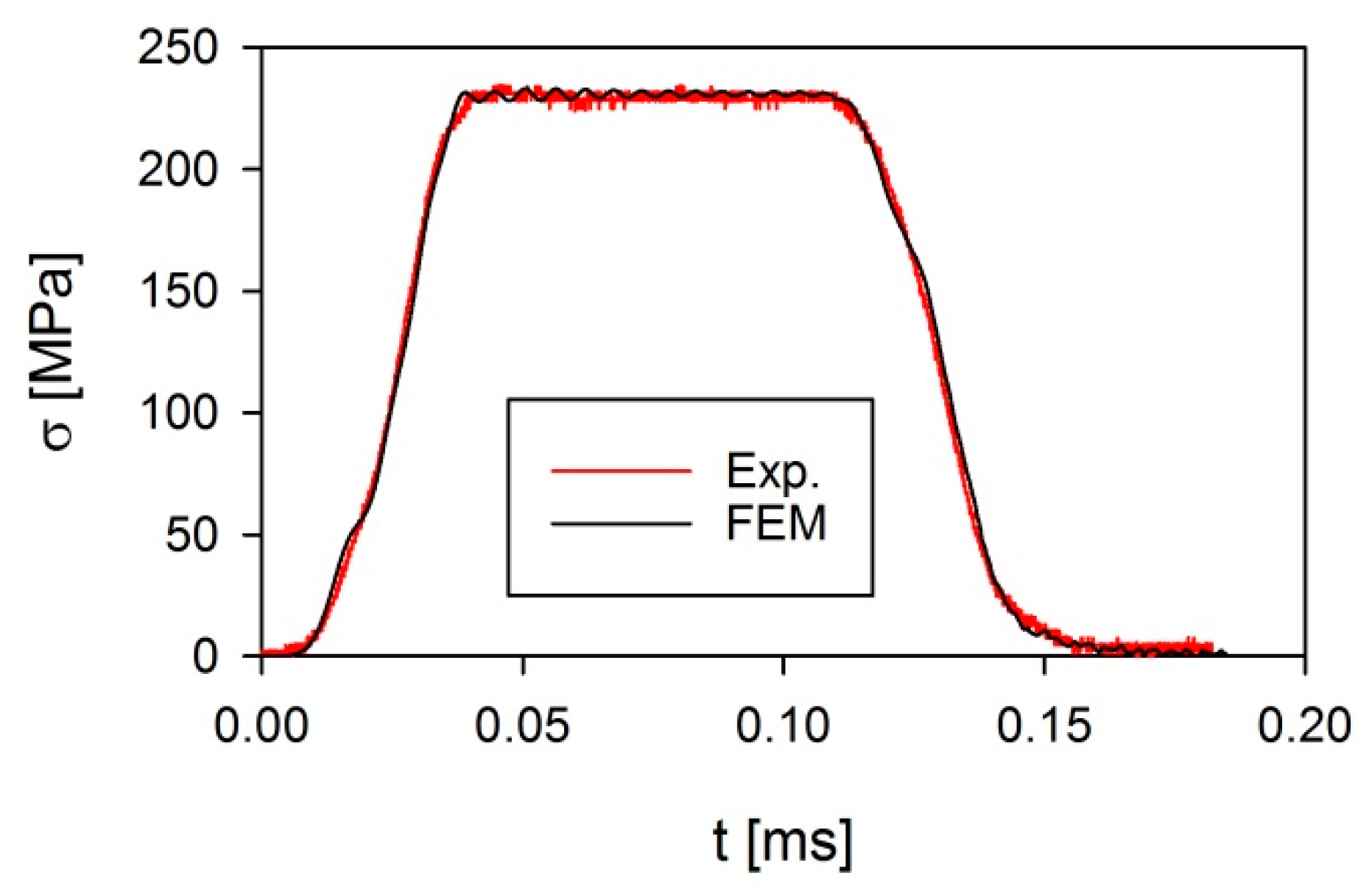
Validation tests were carried out for the case of striker impact, with a velocity of 11.76 m/s, into the shaper made of copper sheet with a thickness of 0.201 mm and a diameter of 3 mm (Figure 5) [14]. Good agreement was shown between the experimental results and the numerical analyses.
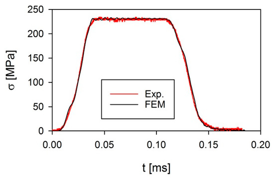
Figure 5.
A comparison of the incident wave profiles obtained from numerical (FEM) and experimental (Exp.) analysis; striker velocity 11.76 m/s, copper shaper h = 0.201 mm and ϕ = 3 mm [14].
4. Results and Discussion
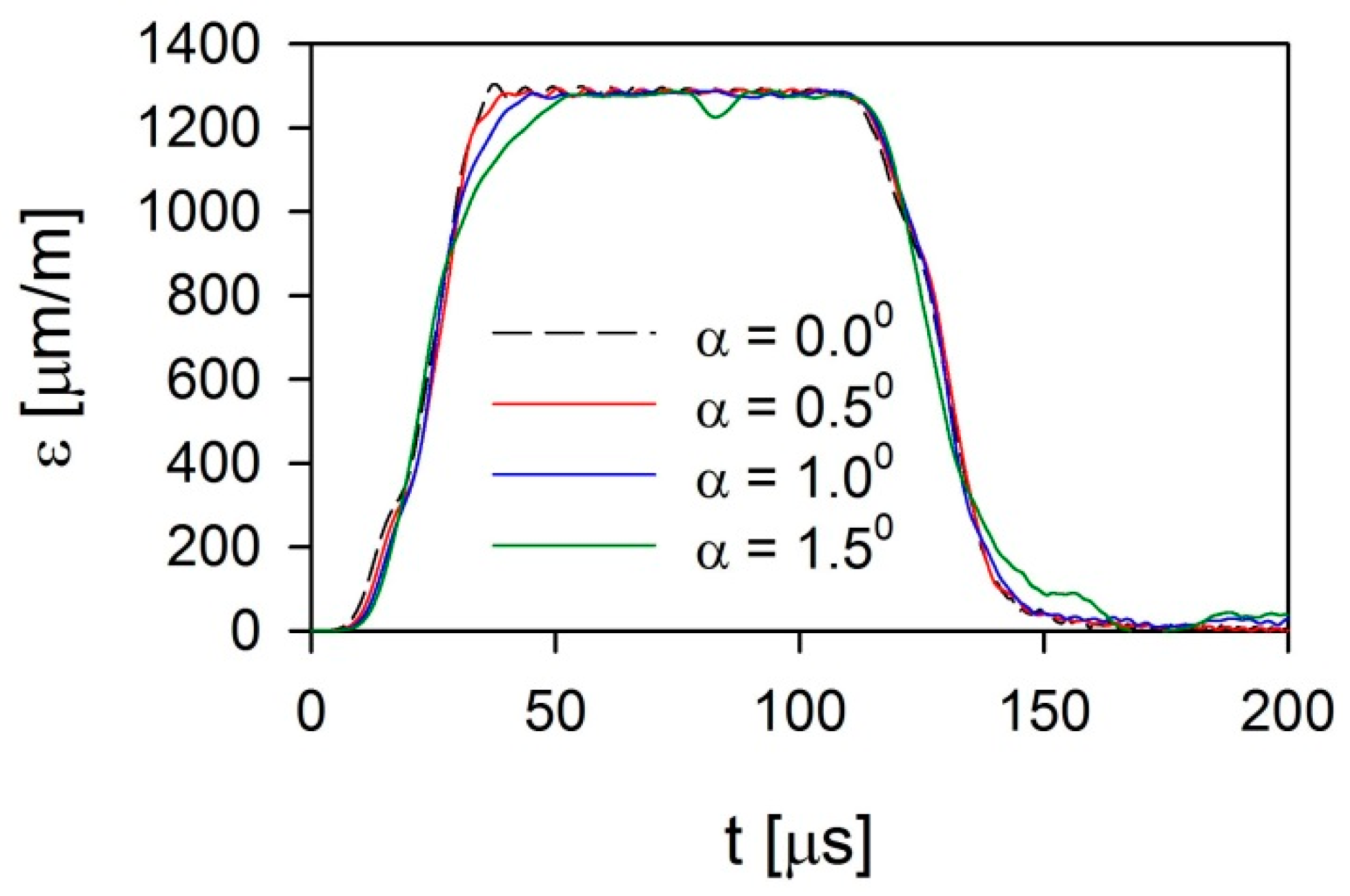
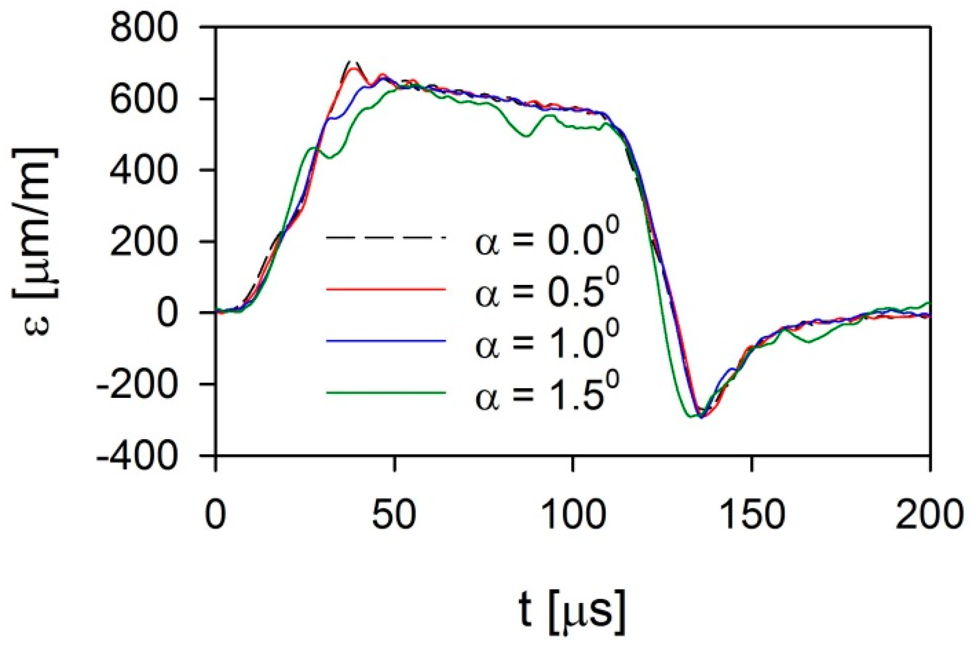
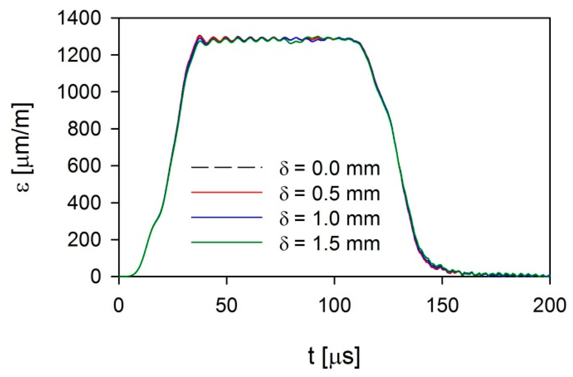
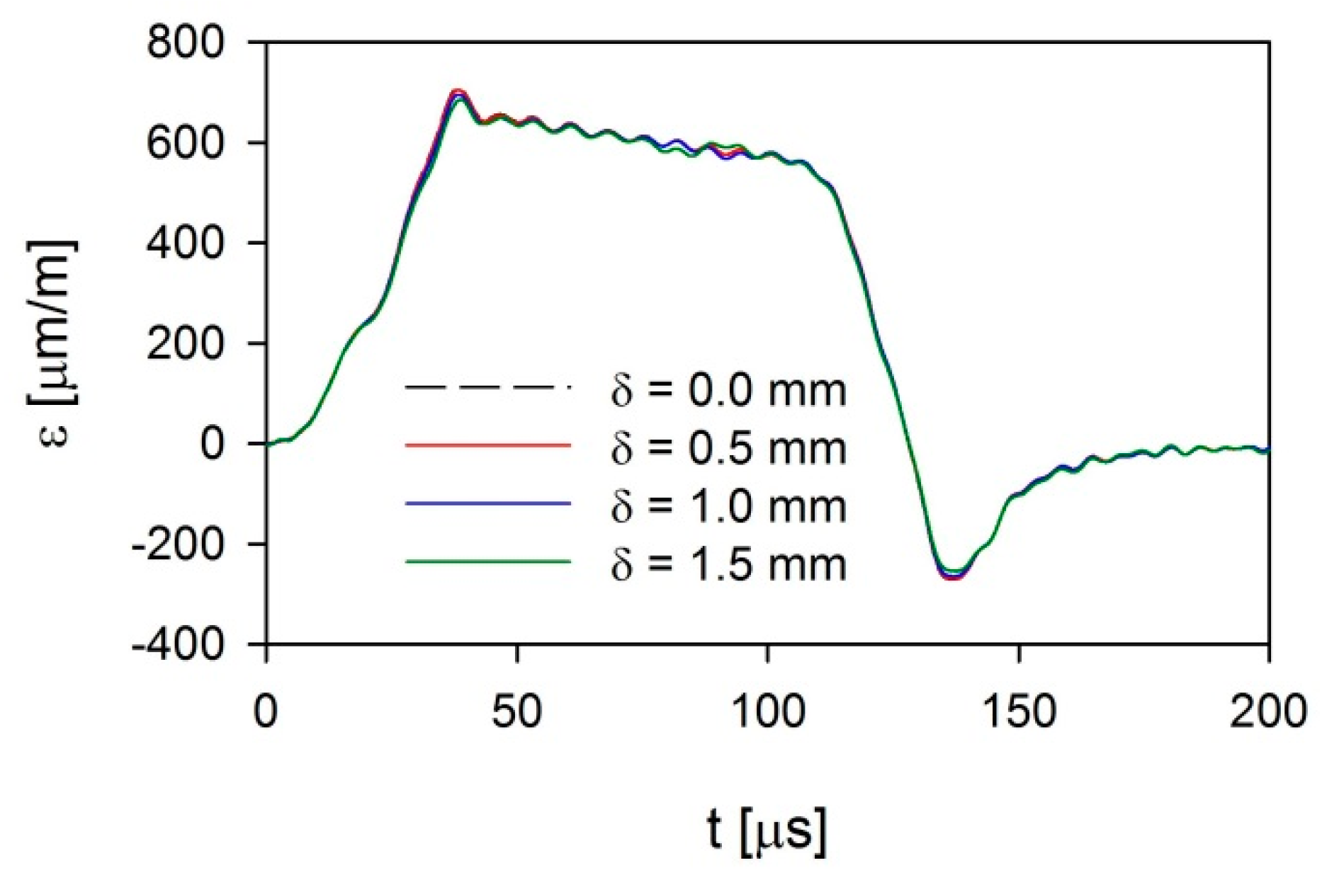
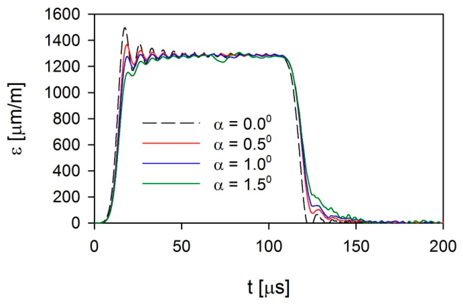
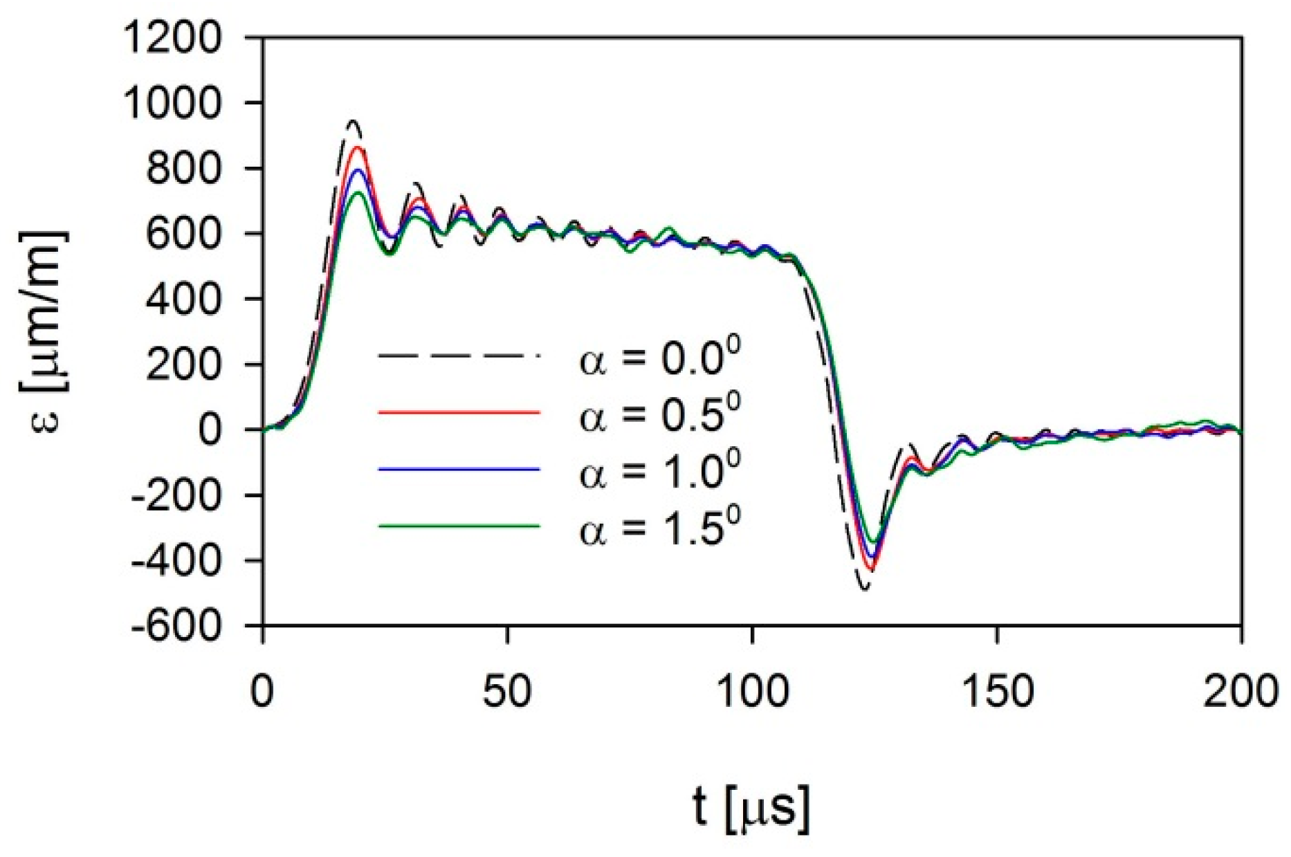
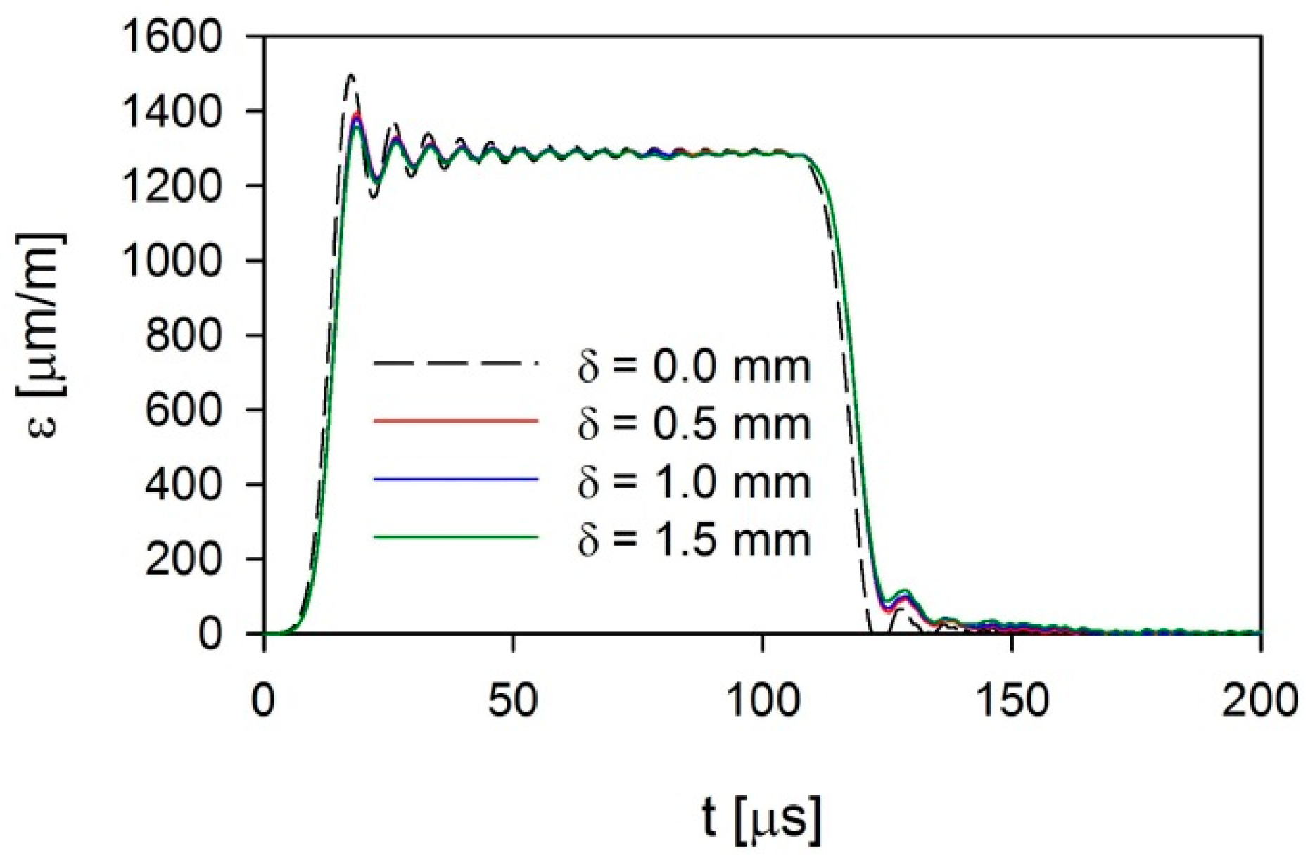
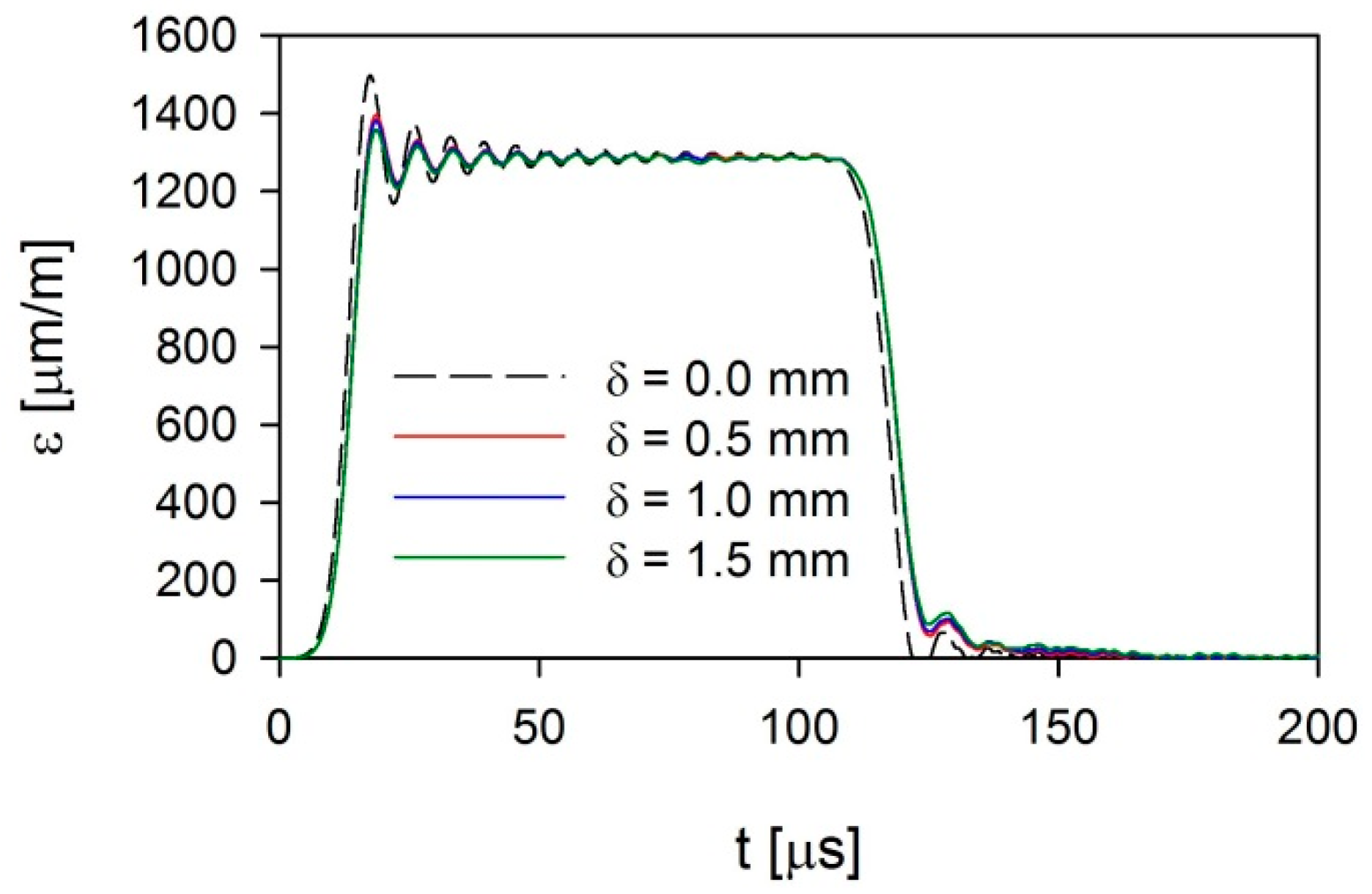
The influence of imperfections shown in Figure 2 for the case using a copper pulse shaper is shown in Figure 6, Figure 7, Figure 8 and Figure 9. Figure 6 and Figure 7 show the curves for an imperfection in the form of an inclination angle α in the range of 0 to 1.5° for both the incident and reflected signals, respectively. The next figures present the same curves as related to an imperfection in the form of a neutral axis offset (δ = 0–1.5 mm) of the incident bar and the striker.
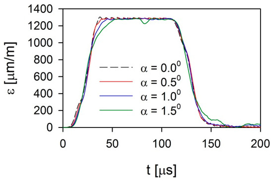
Figure 6.
Incident-disturbed pulses for SHPB using a pulse shaper for an imperfection in the form of an inclination angle α between the striker and input bar.
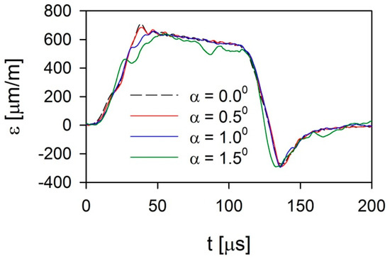
Figure 7.
Reflected disturbed pulses for SHPB using a pulse shaper for an imperfection in the form of inclination angle α between the striker and input bar.
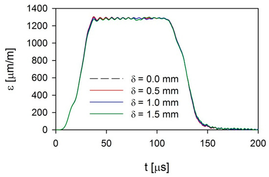
Figure 8.
Incident-disturbed pulses for SHPB using a pulse shaper for an imperfection in the form of neutral axis offset δ.
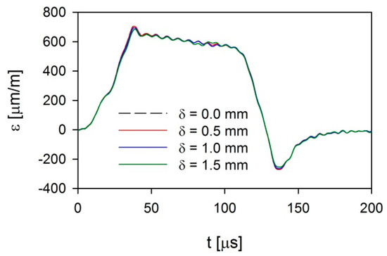
Figure 9.
Reflected disturbed pulses for SHPB using a pulse shaper for an imperfection in the form of neutral axis offset δ.
A significant influence of an imperfection related to the incident angle was visible both in the case of incident (Figure 6) and reflected (Figure 7) pulses. It was manifested as an increase in the incident pulse rise time and the occurrence of disturbances in the plateau stage caused by bending waves. The disturbances in the plateau stage were particularly visible for α = 1.5° and a time of approximately 90 μs. However, the smallest inclination angle of α = 0.5° reduced the high-frequency Pochhammer–Chree oscillations [10,11]. Similar effects occurred in the case of a reflected signal. Nevertheless, the disturbances for the largest inclination angle were not only significantly larger, but they also affected the measurement signal for a much longer time. This was caused by a lower speed of disturbances propagation [13], where the significant effect was visible only in the case of a reflected signal. The occurrence of disturbances of this level resulted, however, from a direct contact between the striker and the input bar despite the use of the pulse shaper. In comparison to the results presented in [13], the level of these disturbances was significantly lower because part of the energy related to the impact of the striker was transferred to the input bar through the deforming pulse shaper. Only a small part of the energy was transmitted through direct contact between the striker and the input bar.
In contrast, in all the analyzed cases of an imperfection related to the displacement of the neutral axes of the striker and the bar, the level of the disturbances caused by a bending wave was much lower not only in the case of the incident pulse (Figure 8) but also for the reflected pulse (Figure 9). This imperfection had a very small influence on the pulse rise time. The pulse disturbances that occurred in the plateau stage for the largest displacement (δ = 1.5 mm) also had a lower amplitude when compared to the data from the previously analyzed case of imperfection. The shape of the disturbance was also different; in the case of the displaced neutral axes, the disturbance had a sinusoid shape with comparable amplitudes. However, when an inclination angle occurred, large differences in the disturbances amplitude occurred. The difference in the pulses’ disturbances resulted from a difference in the position of the contact points between the striker and input bar. The shift of the contact point was greater in the case of an imperfection related to the inclination angle.
A similar situation occurred when a pulse-shaping technique in the form of a striker with a rounding radius of 120 mm (Figure 10, Figure 11, Figure 12 and Figure 13) was applied. In this case, the effects of the imperfection were much smaller. This was especially visible in the case of reflected pulses and the imperfections related to an inclination angle (Figure 11), where the occurring disorder only slightly affected the impulse course. In contrast, in the case of an imperfection related to the displacement of the neutral axes, the influence of the existing axis shift was negligible in the considered range of the parameter δ (Figure 12 and Figure 13). It should be noted that this disorder amplitude was related to the distance between the end of the barrel and the occurrence of clearance between the striker and the input bar. If these parameters increased, the amplitude of the disturbances in the signals increased.
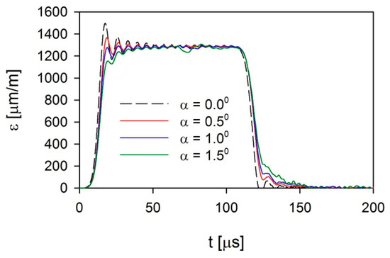
Figure 10.
Incident-disturbed pulses for SHPB using a rounded striker for an imperfection in the form of inclination angle α between the striker and input bar.
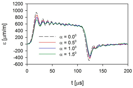
Figure 11.
Reflected disturbed pulses for SHPB using a rounded striker for an imperfection in the form of inclination angle α between the striker and input bar.
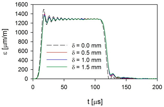
Figure 12.
Incident-disturbed pulses for SHPB using a rounded striker for an imperfection in the form of neutral axis offset δ.
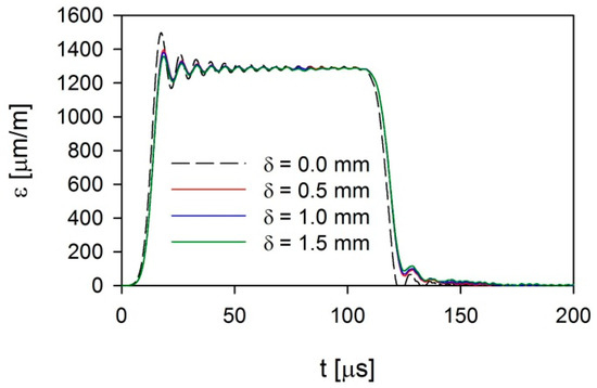
Figure 13.
Reflected disturbed pulses for SHPB using a rounded striker for an imperfection in the form of neutral axis offset δ.
Both types of the analyzed imperfections, especially the inclination angle, significantly affected the reduction of the high-frequency Pochhammer–Chree oscillations.
5. Conclusions
Imperfect conditions in the SHPB technique, in the form of imperfect position of the striker and input bar, have been numerically analyzed. The inclination angle imperfection has a significant impact on the signal disturbances in the SHPB technique for angles larger than 1°, regardless of the pulse-shaping technique used. The use of a rounded striker significantly limits the vibration flexural modes. It allows tests to be conducted without an increase in the measurement uncertainty when the inclination angle imperfection is slightly larger than 1° or the offset of the neutral axis is not greater than 1.5 mm. If the pulse shaper is used, these values are smaller and amount to 0.5 and 1 mm, respectively. In all of the analyzed cases, slight imperfections cause a reduction in Pochhammer–Chree oscillations. It should be noted that the magnitude of the recorded disturbances is affected by the position of strain gauges and the method of supporting the measuring bars.
Author Contributions
Conceptualization, R.P.; Investigation, R.P. and M.K.; Methodology, R.P.; Supervision, R.P.; Visualization, M.K.; Writing—original draft, R.P. and M.K. All authors have read and agreed to the published version of the manuscript.
Funding
The support of Military University of Technology grant PBS 23-937 is gratefully acknowledged.
Conflicts of Interest
The authors declare no conflict of interest.
References
- Chen, W.; Song, B. Split Hopkinson (Kolsky) Bar: Design, Testing and Applications; Springer Science and Business Media: Heidelberg, Germany, 2011. [Google Scholar]
- Chen, W.; Luo, H. Dynamic compressive responses of intact and damaged ceramics from a single split Hopkinson pressure bar experiment. Exp. Mech. 2004, 44, 295–299. [Google Scholar] [CrossRef]
- Lu, Y.; Li, Q. Appraisal of Pulse-Shaping Technique in Split Hopkinson Pressure Bar Tests for Brittle Materials. Int. J. Prot. Struct. 2010, 1, 363–390. [Google Scholar] [CrossRef]
- Cloete, T.; Van Der Westhuizen, A.; Kok, S.; Nurick, G.N. A tapered striker pulse shaping technique for uniform strain rate dynamic compression of bovine bone. In DYMAT—International Conference on the Mechanical and Physical Behaviour of Materials under Dynamic Loading, Brussels, Belgium, 7–11 September 2009; Song, B., Casem, D., Kimberley, J., Eds.; Springer Science Business Media: Heidelberg, Germany, 2009; Volume 1, pp. 901–907. [Google Scholar]
- Bekker, A.; Cloete, T.; Chinsamy-Turan, A.; Nurick, G.; Kok, S. Constant strain rate compression of bovine cortical bone on the Split-Hopkinson Pressure Bar. Mater. Sci. Eng. C 2015, 46, 443–449. [Google Scholar] [CrossRef] [PubMed]
- Baranowski, P.; Małachowski, J.; Gieleta, R.; Damaziak, K.; Mazurkiewicz, Ł.; Kolodziejczyk, D. Numerical study for determination of pulse shaping design variables in SHPB apparatus. Bull. Pol. Acad. Sci. Tech. Sci. 2013, 61, 459–466. [Google Scholar] [CrossRef]
- Ellwood, S.; Griffiths, L.J.; Parry, D.J. Materials testing at high constant strain rates. J. Phys. E Sci. Instrum. 1982, 15, 280–282. [Google Scholar] [CrossRef]
- Jankowiak, T.; Rusinek, A.; Łodygowski, T. Validation of the Klepaczko–Malinowski model for friction correction and recommendations on Split Hopkinson Pressure Bar. Finite Elem. Anal. Des. 2011, 47, 1191–1208. [Google Scholar] [CrossRef]
- Moćko, W. Analysis of the Impact of the Frequency Range of the Tensometer Bridge and Projectile Geometry on the Results of Measurements by the Split Hopkinson Pressure Bar Method. Metrol. Meas. Syst. 2013, 20, 555–564. [Google Scholar] [CrossRef]
- Pochhammer, L. On the propagation velocities of small oscillations in an unlimited isotropic circular cylinder. J. Reine Angew. Math. 1876, 81, 324–326. [Google Scholar]
- Chree, C. The equations of an isotropic elastic solid in polar and cylindrical coordinates, their solutions and applications. Trans. Camb. Philos. Soc. 1889, 14, 250–369. [Google Scholar]
- Kariem, M.A.; Beynon, J.; Ruan, D. Misalignment effect in the split Hopkinson pressure bar technique. Int. J. Impact Eng. 2012, 47, 60–70. [Google Scholar] [CrossRef]
- Wu, X.; Yin, Q.; Wei, Y.; Huang, C. Effects of imperfect experimental conditions on stress waves in SHPB experiments. Acta Mech. Sin. 2015, 31, 827–836. [Google Scholar] [CrossRef][Green Version]
- Panowicz, R.; Janiszewski, J.; Kochanowski, K. The non-axisymmetric pulse shaper position influence on SHPB experiment data. J. Theor. App. Mech. 2018, 56, 873–886. [Google Scholar] [CrossRef]
- Hallquist, J.O. Ls-Dyna, Theoretical Manual; Livermore Software Technology Corporation: Livermore, CA, USA, 2006. [Google Scholar]
- Malinowski, J.Z.; Klepaczko, J.R. A unified analytic and numerical approach to specimen behaviour in the Split-Hopkinson pressure bar. Int. J. Mech. Sci. 1986, 28, 381–391. [Google Scholar] [CrossRef]
- Gorham, D. An effect of specimen size in the high strain rate compression test. J. Phys.IV Colloq. 1991, 1, 411–418. [Google Scholar] [CrossRef]
- Gray, G.T. Classic split-Hopkinson pressure bar testing. In Mechanical Testing and Evaluation; Kuhn, H., Medlin, D., Eds.; ASM International: Materials Park, OH, USA, 2000; Volume 8, pp. 462–476. [Google Scholar]
- Forrestal, M.J.; Wright, T.W.; Chen, W. The effect of radial inertia on brittle samples during the split Hopkinson pressure bar test. Int. J. Impact Eng. 2007, 34, 405–411. [Google Scholar] [CrossRef]
- Davies, E.D.H.; Hunter, S.C. The dynamic compression testing of solids by the method of the split Hopkinson pressure bar. J. Mech. Phys. Solids 1963, 11, 155–179. [Google Scholar] [CrossRef]
- Panowicz, R. Analysis of selected contact algorithms types in terms of their parameters selection. J. KONES 2013, 20, 263–268. [Google Scholar] [CrossRef]
- Konyukhov, A.; Schweizerhof, K. Computational Contact Mechanics—Geometrically Exact Theory for Arbitrary Shaped Bodies; Springer Science Business Media: Heidelberg, Germany, 2013. [Google Scholar]
- Fischer, K.A.; Wriggers, P. Mortar based frictional contact formulation for higher order interpolations using the moving friction cone. Comput. Methods Appl. Mech. Eng. 2006, 195, 5020–5036. [Google Scholar] [CrossRef]
- Wang, Z.; Li, P. Characterisation of dynamic behaviour of alumina ceramics: Evaluation of stress uniformity. AIP Adv. 2015, 5, 107224. [Google Scholar] [CrossRef]
- Tasdemirci, A.; Ergönenç, Ç.; Guden, M. Split Hopkinson pressure bar multiple reloading and modeling of a 316 L stainless steel metallic hollow sphere structure. Int. J. Impact Eng. 2010, 37, 250–259. [Google Scholar] [CrossRef]
- Liu, P.; Hu, D.; Wu, Q.; Liu, X. Sensitivity and uncertainty analysis of interfacial effect in SHPB tests for concrete-like materials. Constr. Build. Mater. 2018, 163, 414–427. [Google Scholar] [CrossRef]
- Hartley, R.; Cloete, T.; Nurick, G. An experimental assessment of friction effects in the split Hopkinson pressure bar using the ring compression test. Int. J. Impact Eng. 2007, 34, 1705–1728. [Google Scholar] [CrossRef]
- Panowicz, R.; Janiszewski, J. Tensile Split Hopkinson Bar Technique: Numerical Analysis of the Problem of Wave Disturbance and Specimen Geometry Selection. Metrol. Meas. Syst. 2016, 23, 425–436. [Google Scholar] [CrossRef]
- Johnson, G.R.; Cook, W.H. A constitutive model and data for metals subjected to large strains, high strain rates and high temperatures. In Proceedings of the Seventh International Symposium on Ballistics, The Hague, The Nederland, 19–21 April 1983; pp. 541–547. [Google Scholar]
- Steinberg, D.J. Equation of State and Strength Properties of Selected Materials. LLNL Report UCRL-MA-106439; Lawrence Livermore National Laboratory: Livermore, OH, USA, 1996. [Google Scholar]
- Srivastava, A.K.; Ozel, T.; Sima, M. Finite element simulation of high speed machining Ti-6Al-4V alloy using modified material models. In Proceedings of the Transactions of the North American Manufacturing Research Institution of SME, Kingston, ON, Canada, 26–28 May 2010; Volume 38, pp. 49–56. [Google Scholar]
- Grazka, M.; Janiszewski, J. Identification of Johnson-Cook equation constants using finite element method. Eng. Trans. 2012, 60, 215–223. [Google Scholar]
- Courant, R.; Friedrichs, K.; Lewy, H. On the Partial Difference Equations of Mathematical Physics. IBM J. Res. Dev. 1967, 11, 215–234. [Google Scholar] [CrossRef]
© 2020 by the authors. Licensee MDPI, Basel, Switzerland. This article is an open access article distributed under the terms and conditions of the Creative Commons Attribution (CC BY) license (http://creativecommons.org/licenses/by/4.0/).

