Electromagnetic Scattering from Surfaces with Curved Wedges Using the Method of Auxiliary Sources (MAS)
Abstract
1. Introduction
2. MAS for Eye-Shaped Scatterers
3. Improvement of the Auxiliary Surface Layout
4. Results
4.1. PEC Scatterer
4.2. Lossless dielectric scatterer
4.3. Lossy Dielectric Scatterer
4.4. Investigation of the Solution Behavior for Various Geometry Modifications
5. Discussion
6. Conclusions
Author Contributions
Funding
Conflicts of Interest
References
- La Spada, L.; Vegni, L. Near-zero-index wires. Opt. Express 2017, 25, 23699–23708. [Google Scholar] [CrossRef] [PubMed]
- Pacheco-Peña, V.; Engheta, N.; Kuznetsov, S.; Gentselev, A.; Beruete, M. All-metallic epsilon-near-zero graded-index converging lens at terahertz frequencies. In Proceedings of the 12th European Conference on Antennas and Propagation (EuCAP 2018), London, UK, 9–13 April 2018; pp. 320–324. [Google Scholar]
- Greybush, N.J.; Pacheco-Peña, V.; Engheta, N.; Murray, C.B.; Kagan, C.R. Plasmonic optical and chiroptical response of self-assembled au nanorod equilateral trimers. ACS Nano 2019, 13, 1617–1624. [Google Scholar] [CrossRef] [PubMed]
- La Spada, L.; Spooner, C.; Haq, S.; Hao, Y. Curvilinear metasurfaces for surface wave manipulation. Sci. Rep. 2019, 9, 3107. [Google Scholar] [CrossRef] [PubMed]
- Lee, I.H.; Yoo, D.; Avouris, P.; Low, T.; Oh, S.H. Graphene acoustic plasmon resonator for ultrasensitive infrared spectroscopy. Nat. Nanotechnol. 2019, 14, 313–319. [Google Scholar] [CrossRef] [PubMed]
- La Spada, L.; Vegni, L. Electromagnetic nanoparticles for sensing and medical diagnostic applications. Materials 2018, 11, 603. [Google Scholar] [CrossRef]
- Harrington, R.F. Field Computation by Moment Methods; Mc Millan: New York, NY, USA, 1968. [Google Scholar]
- Vegni, L.; Cichetti, R.; Capece, P. Spectral dyadic Green’s function formulation for planar integrated structures. IEEE Trans. Antennas Propag. 1988, 36, 1057–1065. [Google Scholar] [CrossRef]
- Volakis, J.L.; Chatterjee, A.; Kempel, L.C. Finite Element Method Electromagnetics: Antennas, Microwave Circuits, and Scattering Applications; Wiley-IEEE Press: Hoboken, NJ, USA, 1998. [Google Scholar]
- Taflove, A.; Hagness, S.C. Computational Electrodynamics: The Finite-Difference Time-Domain Method, 3rd ed.; Artech House: Norwood, MA, USA, 2005. [Google Scholar]
- Christopoulos, C. The Transmission-Line Modeling Method: TLM; IEEE Press: Piscataway, NJ, USA, 1995. [Google Scholar]
- La Spada, L. Metasurfaces for advanced sensing and diagnostics. Sensors 2019, 19, 355. [Google Scholar] [CrossRef]
- Pacheco-Peña, V.; Beruete, M.; Rodríguez-Ulibarri, P.; Engheta, N. On the performance of an ENZ-based sensor using transmission line theory and effective medium approach. New J. Phys. 2019, 21, 043056. [Google Scholar] [CrossRef]
- Estakhri, N.M.; Edwards, B.; Engheta, N. Inverse-designed metastructures that solve equations. Science 2019, 363, 1333–1338. [Google Scholar] [CrossRef]
- Popovidi-Zaridze, R.S.; Tsverikmazashvili, Z.S. Numerical study of a diffraction problem by a modified method of non-orthogonal series. Zurnal. Vichislit. Mat. Mat Fiz. 1977, 17, 384–393. [Google Scholar]
- Kaklamani, D.I.; Anastassiu, H.T. Aspects of the method of auxiliary sources (MAS) in computational electromagnetics. IEEE Antennas Propag. Mag. 2002, 44, 48–64. [Google Scholar] [CrossRef]
- Kupradze, V.D. On the approximate solution of problems of mathematical physics. Russ. Math. Surv. 1967, 22, 58–108. [Google Scholar] [CrossRef]
- Avdikos, G.K.; Anastassiu, H.T. Computational cost estimations and comparisons for three methods of applied electromagnetics (MoM, MAS and MMAS). IEEE Antennas Propag. Mag. 2005, 47, 121–129. [Google Scholar] [CrossRef]
- Eisler, S.; Leviatan, Y. Analysis of electromagnetic scattering from metallic and penetrable cylinders with edges using a multifilament current model. IEE Proc. H (Microw. Antennas Propag.) 1989, 136, 431–438. [Google Scholar] [CrossRef]
- Anastassiu, H.T.; Kaklamani, D.I.; Economou, D.P.; Breinbjerg, O. Electromagnetic scattering analysis of coated conductors with edges using the method of auxiliary sources (MAS) in conjunction with the standard impedance boundary condition (SIBC). IEEE Trans. Antennas Propag. 2002, 50, 59–66. [Google Scholar] [CrossRef]
- Senior, T.B.A.; Volakis, J.L. Approximate Boundary Conditions in Electromagnetics; The Institution of Engineering and Technology: London, UK, 1995. [Google Scholar]
- Iatropoulos, V.G.; Anastasiadou, M.T.; Anastassiu, H.T. Application of the method of auxiliary sources (MAS) to the analysis of electromagnetic scattering from dielectric surfaces with curved wedges. In Proceedings of the 13th International Conference on Communications, Electromagnetics and Medical Applications (CEMA’18), Sofia, Bulgaria, 18–20 October 2018; pp. 12–16. [Google Scholar]
- Anastassiu, H.T.; Lymperopoulos, D.G.; Kaklamani, D.I. Accuracy analysis and optimization of the method of auxiliary sources (MAS) for scattering by a circular cylinder. IEEE Trans. Antennas Propag. 2004, 52, 1541–1547. [Google Scholar] [CrossRef]
- Kanellopoulos, S.A.; Panagopoulos, A.D.; Kanellopoulos, J.D. Analysis of the electromagnetic scattering by a raindrop using the method of auxiliary sources. In Proceedings of the IEEE Antennas and Propagation Society Symposium, Monterey, CA, USA, 20–25 June 2004; pp. 4176–4179. [Google Scholar]
- Anastassiu, H.T. A review of electromagnetic scattering analysis for inlets, cavities and open ducts. IEEE Antennas Propag. Mag. 2003, 45, 27–40. [Google Scholar] [CrossRef]
- Fromentin-Denozière, B.; Simon, J.; Tzoulis, A.; Weinmann, F.; Anastassiu, H.T.; Escot Bocanegra, D.; Poyatos Martínez, D.; Fernández Recio, R.; Zdunek, A. Comparative study of miscellaneous methods applied to a benchmark, inlet scattering problem. IET Radar Sonar Navig. 2014, 9, 342–354. [Google Scholar] [CrossRef]
- Anastassiu, H.T.; Petrović, V.V.; Kaklamani, D.I.; Uzunoglu, N.K. Analysis of electromagnetic scattering from jet engine inlets using the method of auxiliary sources (MAS). In Proceedings of the COMCON 7, Seventh Annual International Conference on Advances in Communications and Control, Athens, Greece, 28 June–2 July 1999; pp. 217–226. [Google Scholar]
- La Spada, L.; Vegni, L. Metamaterial-based wideband electromagnetic wave absorber. Opt. Express 2016, 24, 5763–5772. [Google Scholar] [CrossRef]
- La Spada, L.; Haq, S.; Hao, Y. Modeling and design for electromagnetic surface wave devices. Radio Sci. 2017, 52, 1049–1057. [Google Scholar] [CrossRef]
- McManus, T.M.; La Spada, L.; Hao, Y. Isotropic and anisotropic surface wave cloaking techniques. J. Opt. 2016, 18, 044005. [Google Scholar] [CrossRef]
- Qin, F.; Ding, L.; Zhang, L.; Monticone, F.; Chum, C.C.; Deng, J.; Mei, S.; Li, Y.; Teng, J.; Hong, M.; et al. Hybrid bilayer plasmonic metasurface efficiently manipulates visible light. Sci. Adv. 2016, 2, e1501168. [Google Scholar] [CrossRef] [PubMed]
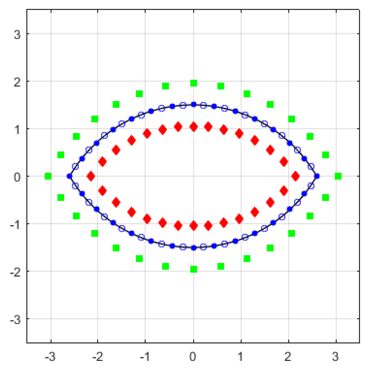
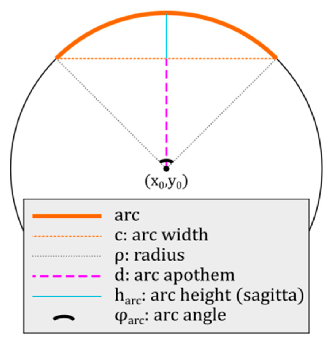
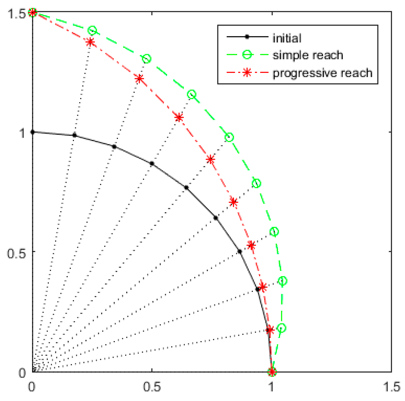
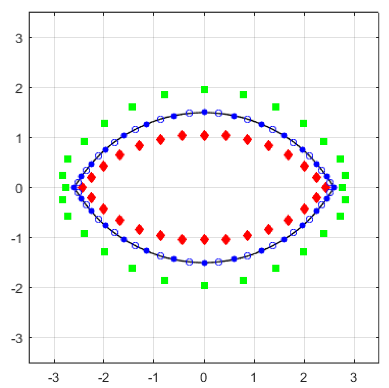

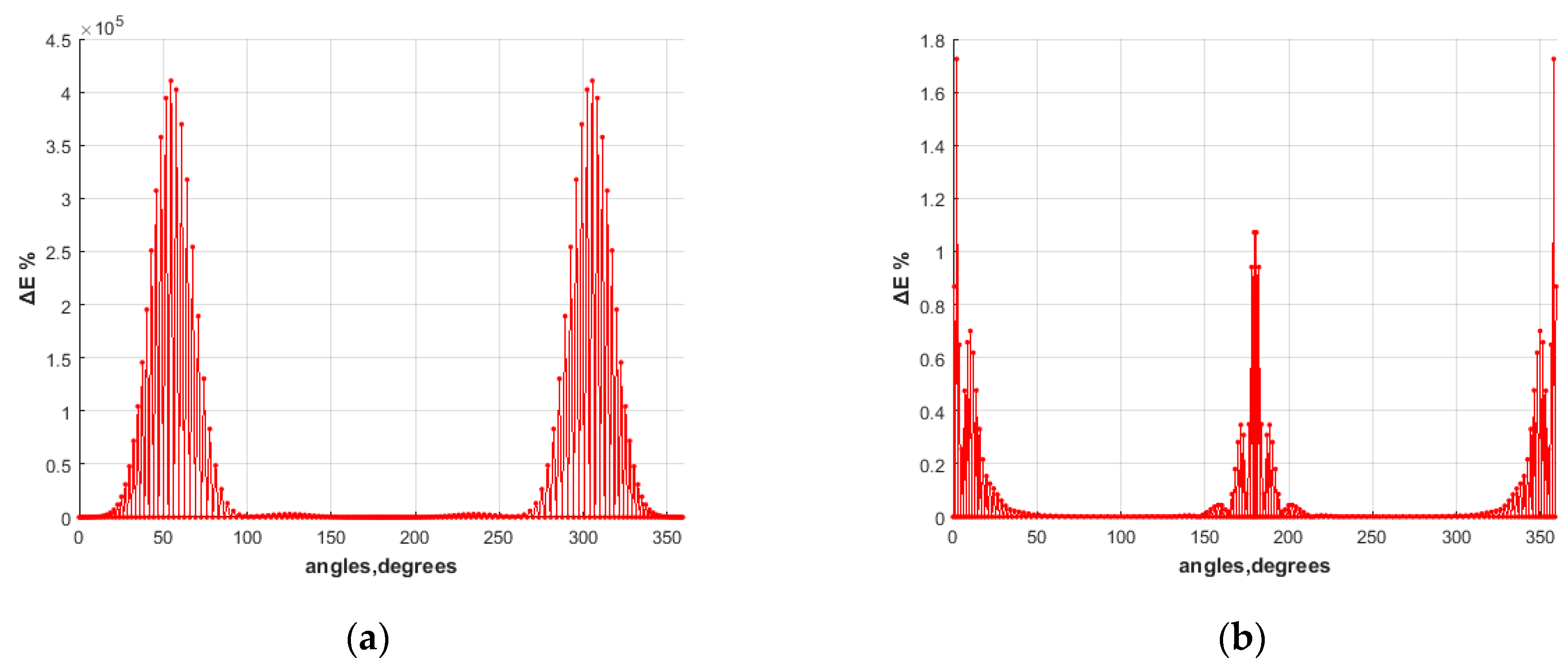
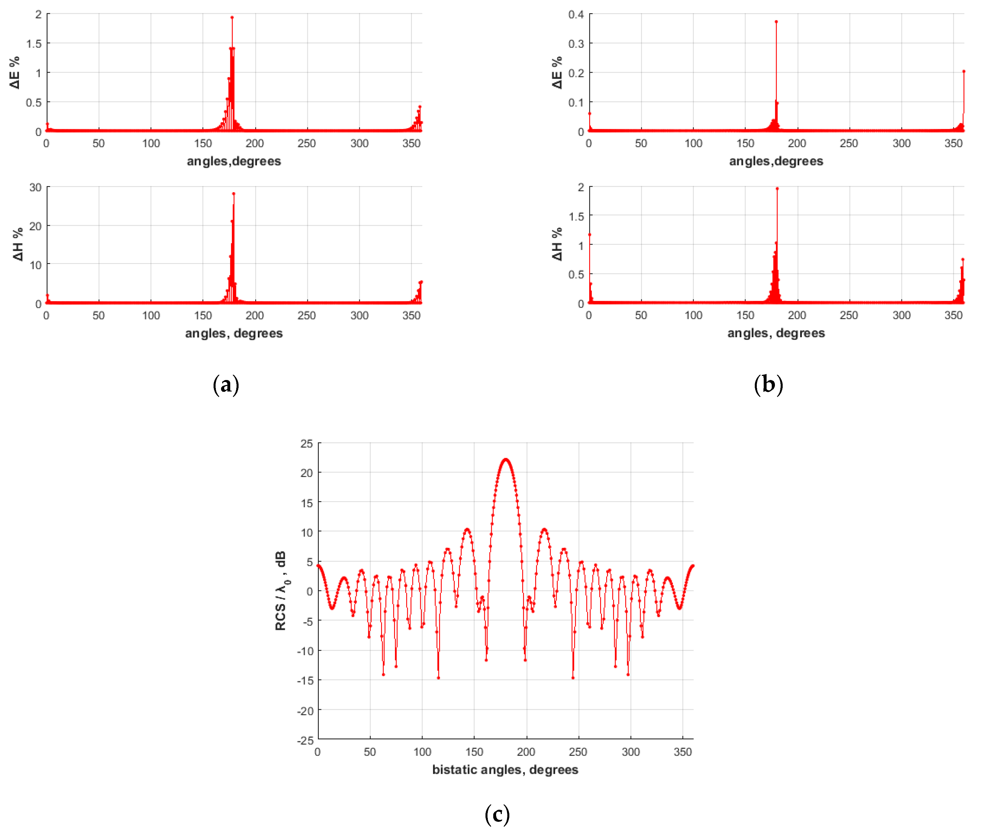
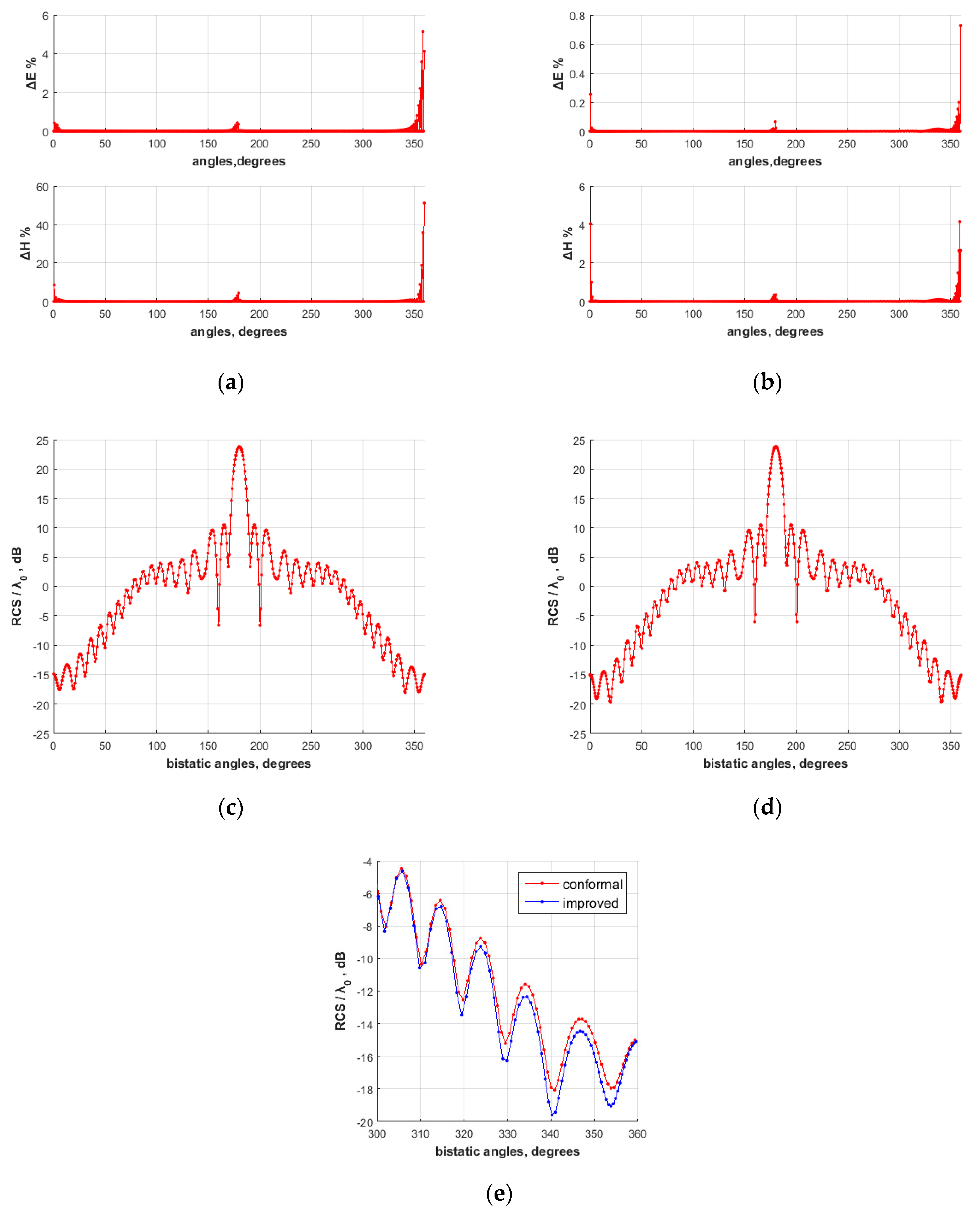


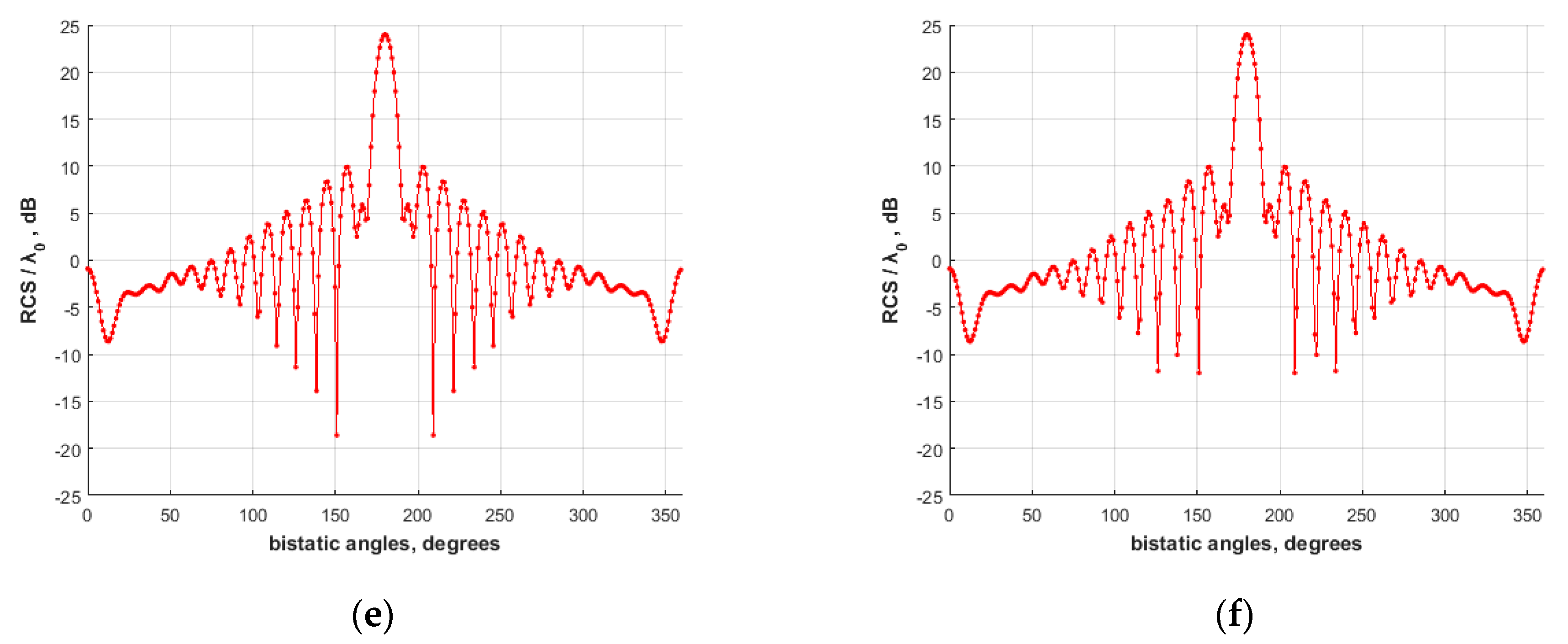
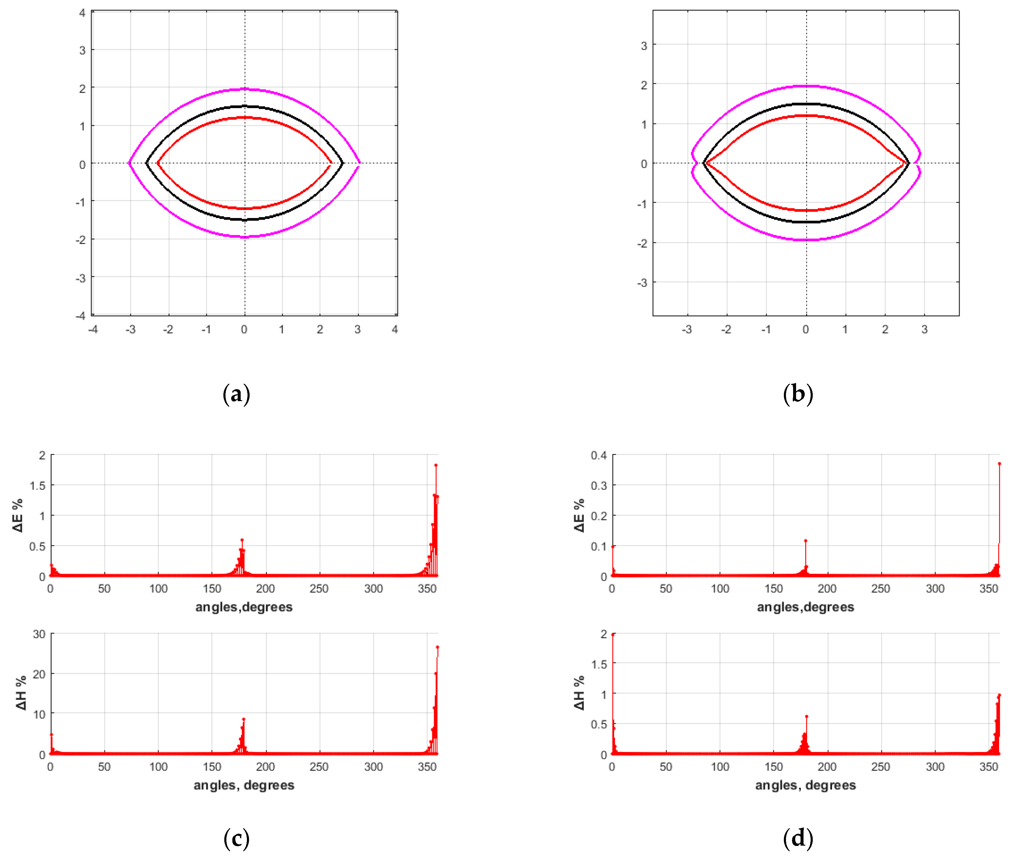
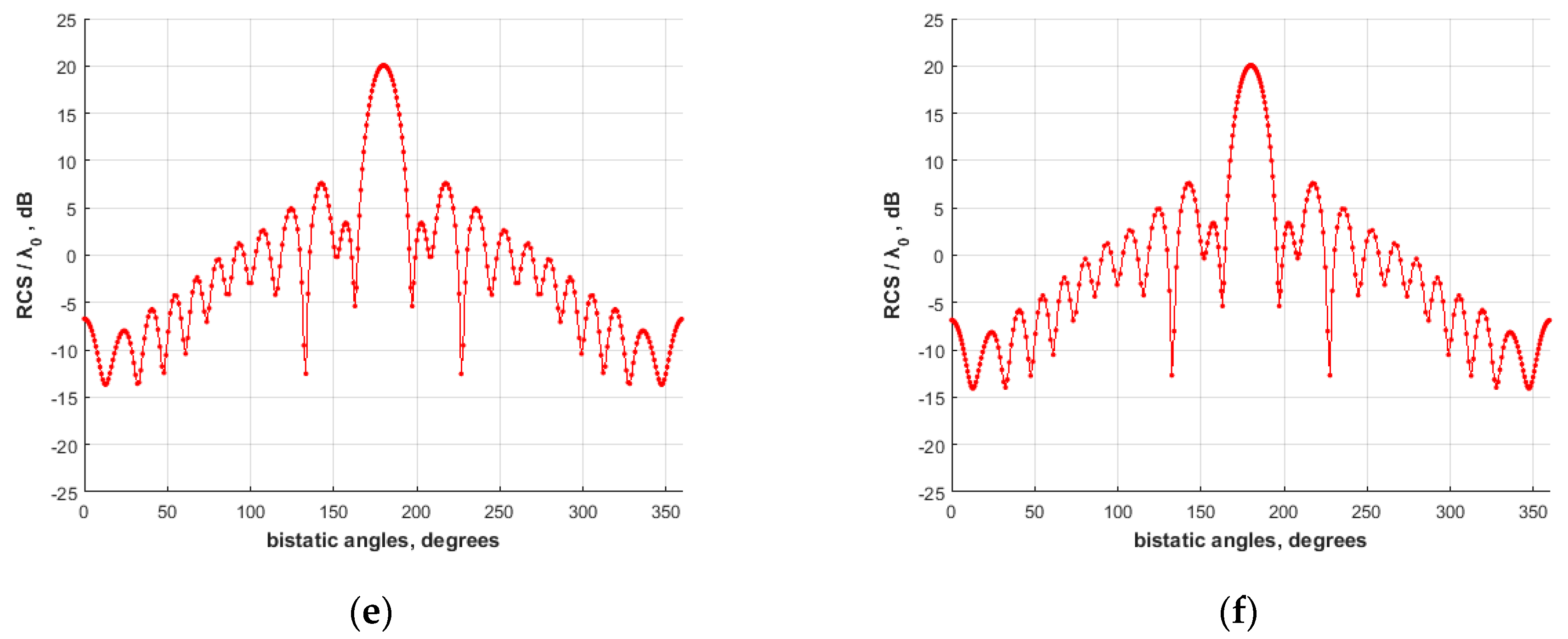
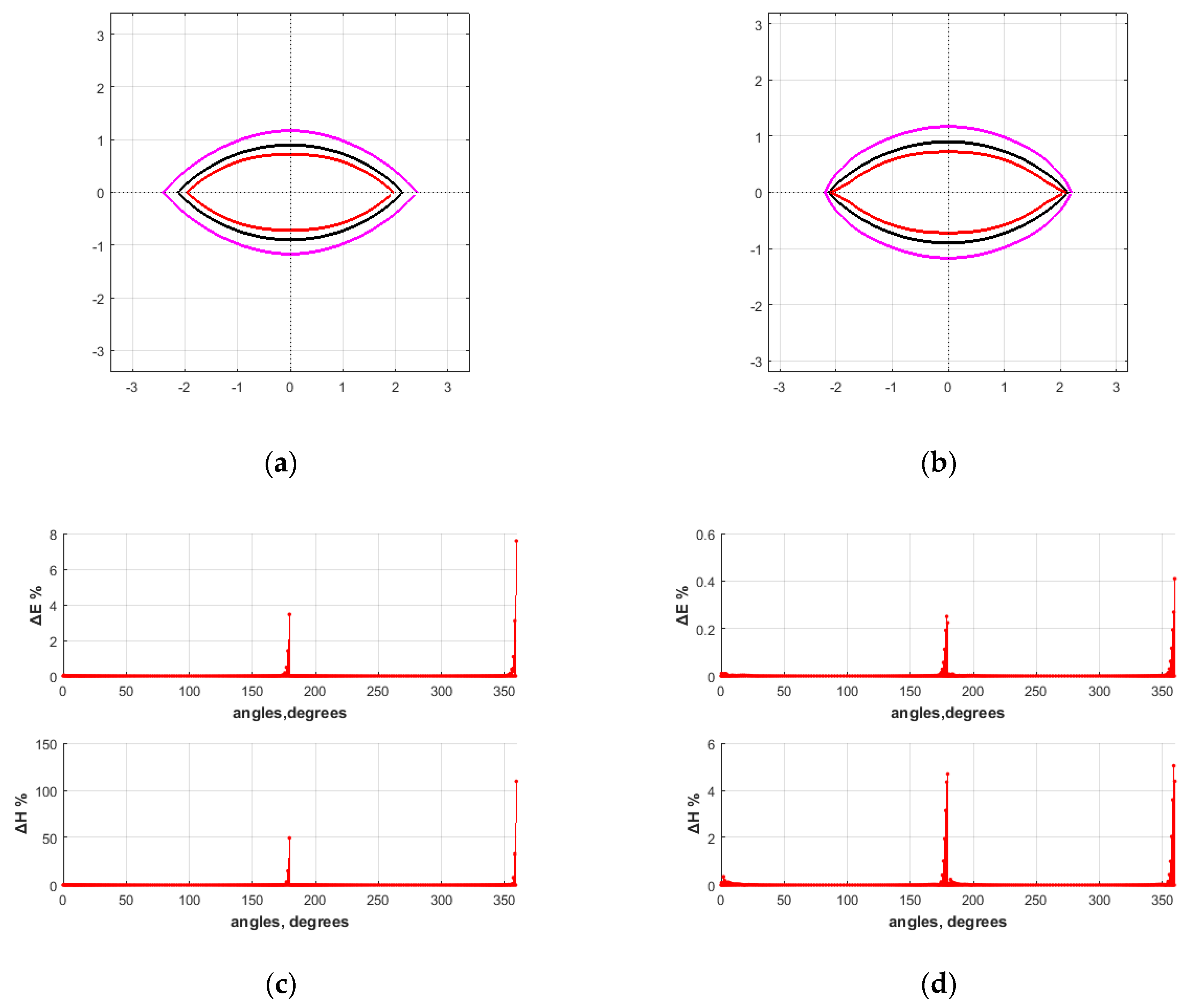
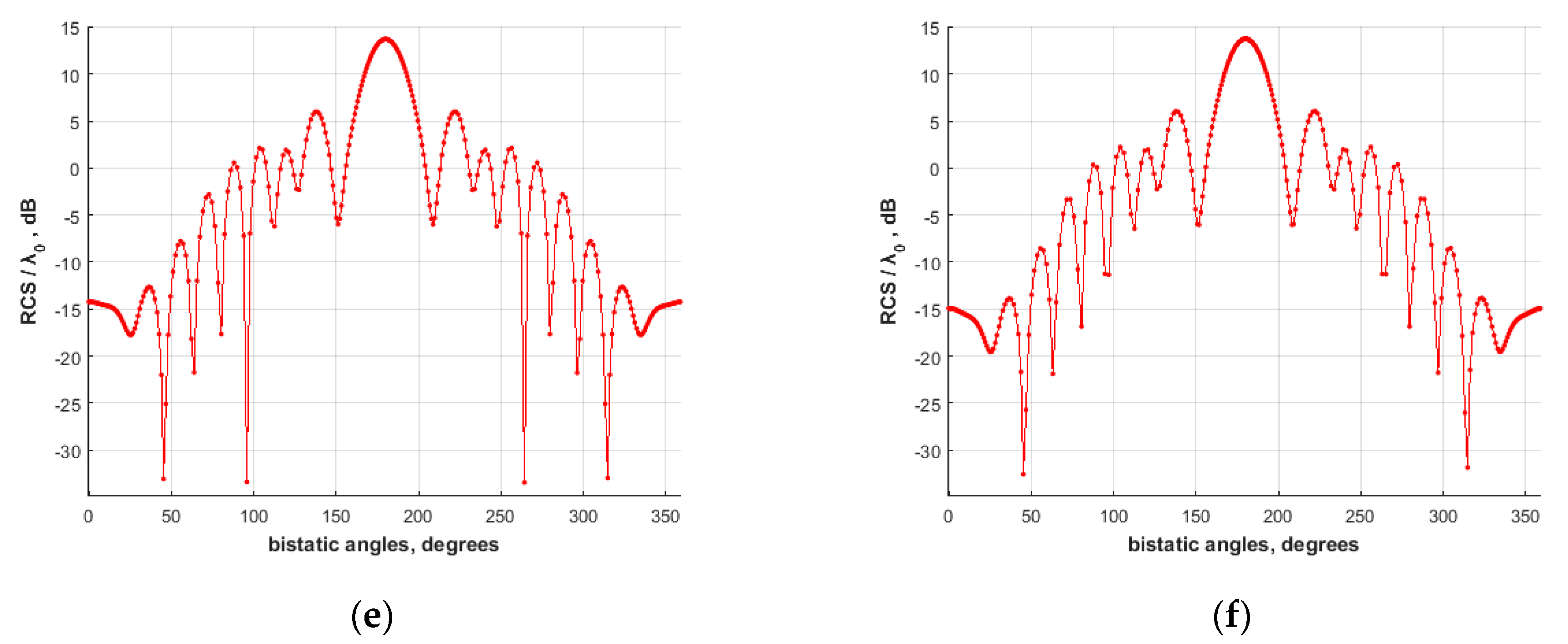
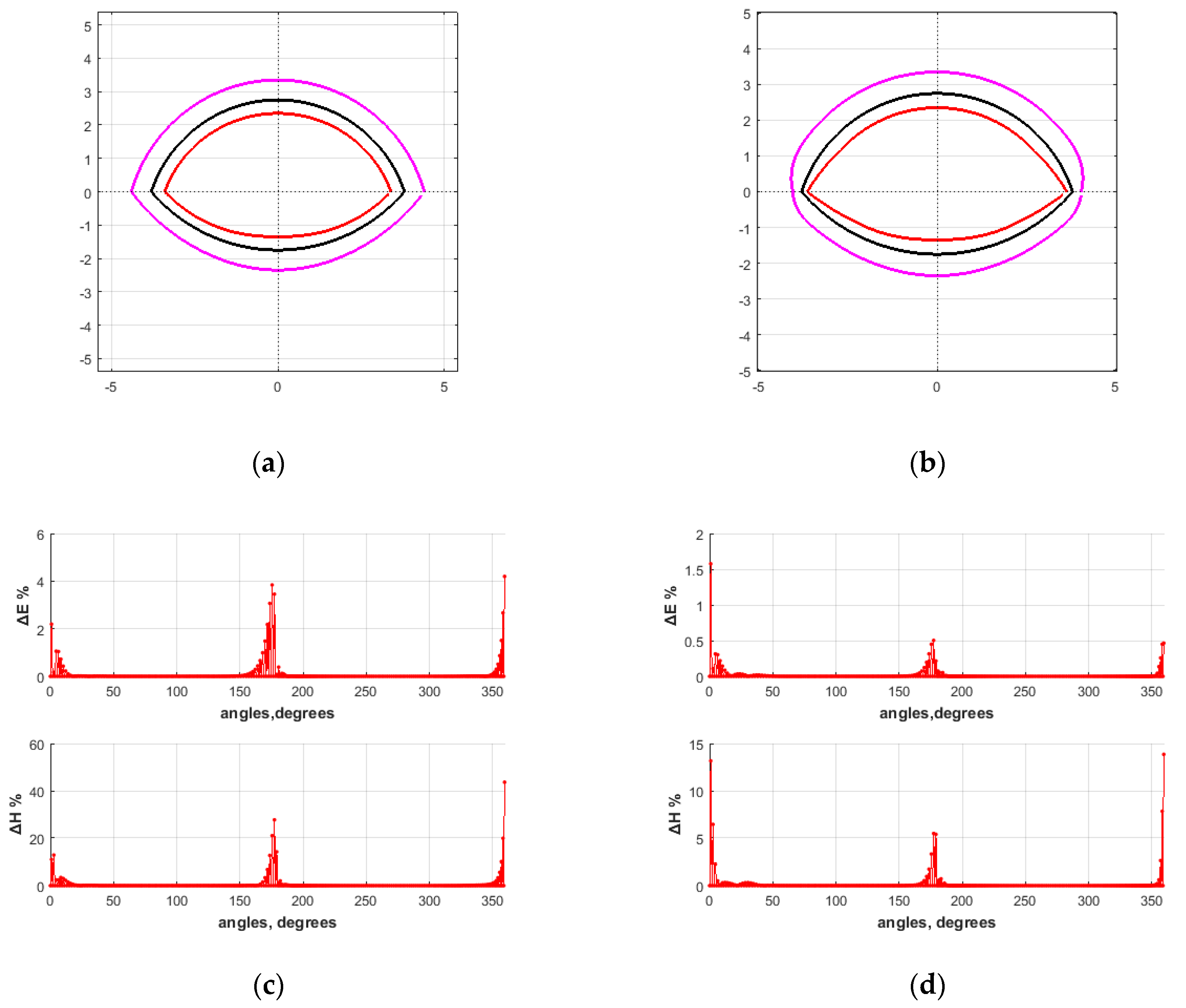
| Arc displacement d | |||
| number of points (ASs, CPs) | 160 | 160 | 156 |
| displaced inner ASs fraction | 1/2 | 1/5 | 1/6 |
| displaced outer ASs fraction | 1/2 | 1/8 | 1/2 |
| inner proximity factor s | 0.55 | 0.75 | 0.74 |
| outer proximity factor s | 0.15 | 0.65 | 0.8 |
| densification factor | 0.94 | 0.8 | 0.8 |
| maximum 1, conformal | |||
| maximum 1, improved | |||
| maximum 1, conformal | 1.09 | ||
| maximum 1, improved |
© 2020 by the authors. Licensee MDPI, Basel, Switzerland. This article is an open access article distributed under the terms and conditions of the Creative Commons Attribution (CC BY) license (http://creativecommons.org/licenses/by/4.0/).
Share and Cite
Iatropoulos, V.G.; Anastasiadou, M.-T.; Anastassiu, H.T. Electromagnetic Scattering from Surfaces with Curved Wedges Using the Method of Auxiliary Sources (MAS). Appl. Sci. 2020, 10, 2309. https://doi.org/10.3390/app10072309
Iatropoulos VG, Anastasiadou M-T, Anastassiu HT. Electromagnetic Scattering from Surfaces with Curved Wedges Using the Method of Auxiliary Sources (MAS). Applied Sciences. 2020; 10(7):2309. https://doi.org/10.3390/app10072309
Chicago/Turabian StyleIatropoulos, Vissarion G., Minodora-Tatiani Anastasiadou, and Hristos T. Anastassiu. 2020. "Electromagnetic Scattering from Surfaces with Curved Wedges Using the Method of Auxiliary Sources (MAS)" Applied Sciences 10, no. 7: 2309. https://doi.org/10.3390/app10072309
APA StyleIatropoulos, V. G., Anastasiadou, M.-T., & Anastassiu, H. T. (2020). Electromagnetic Scattering from Surfaces with Curved Wedges Using the Method of Auxiliary Sources (MAS). Applied Sciences, 10(7), 2309. https://doi.org/10.3390/app10072309


