The Transient Flow behind an Instantaneously Started Circular Cylinder with Two Symmetrical Strips


Abstract
Featured Application
Abstract
1. Introduction
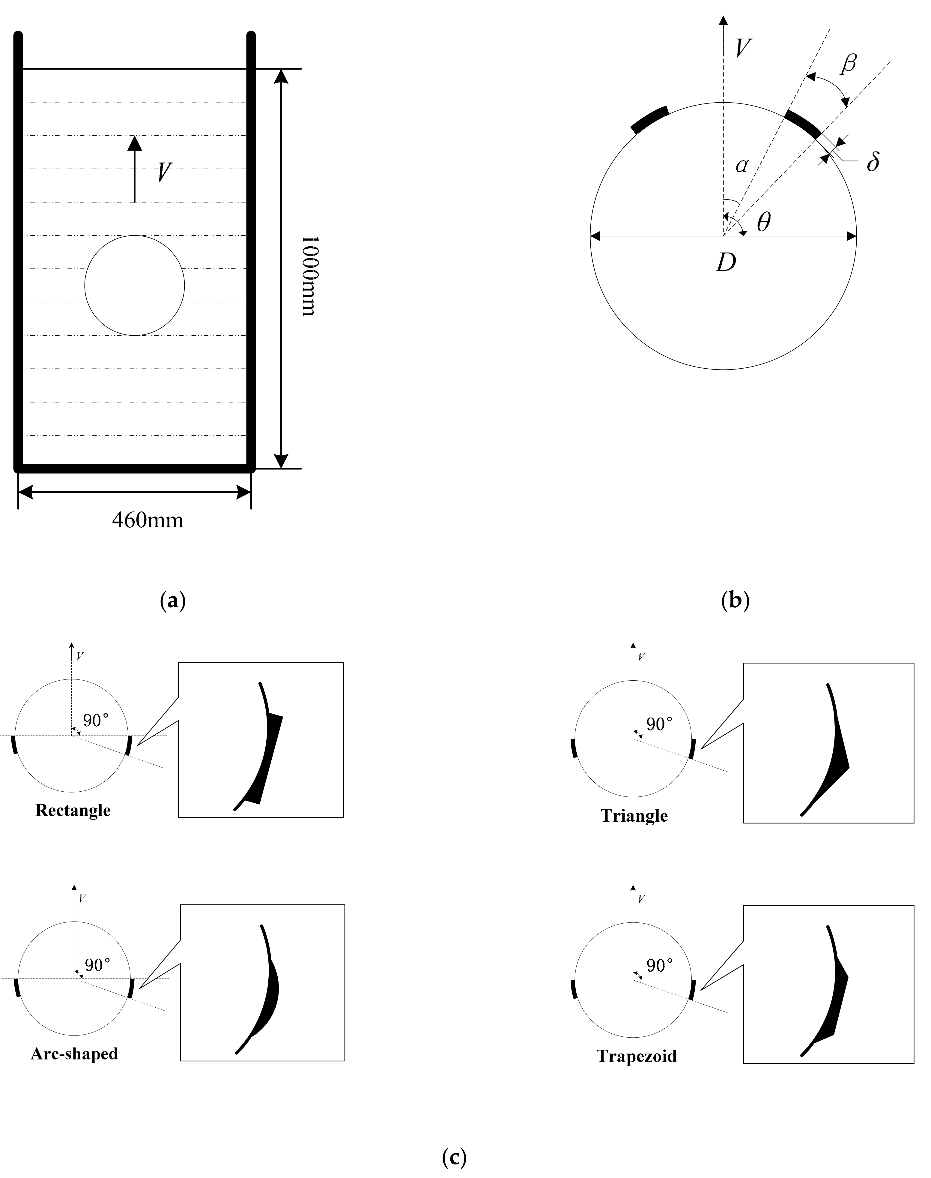
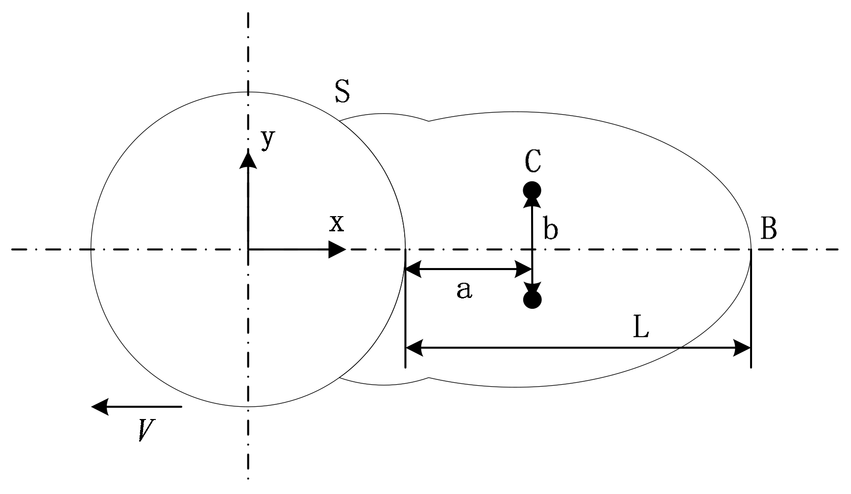
2. Problem Descriptions
3. Theoretical Formulation and Numerical Modeling
3.1. Governing Equations
3.2. Numerical Method
3.3. Dynamic Mesh Algorithm
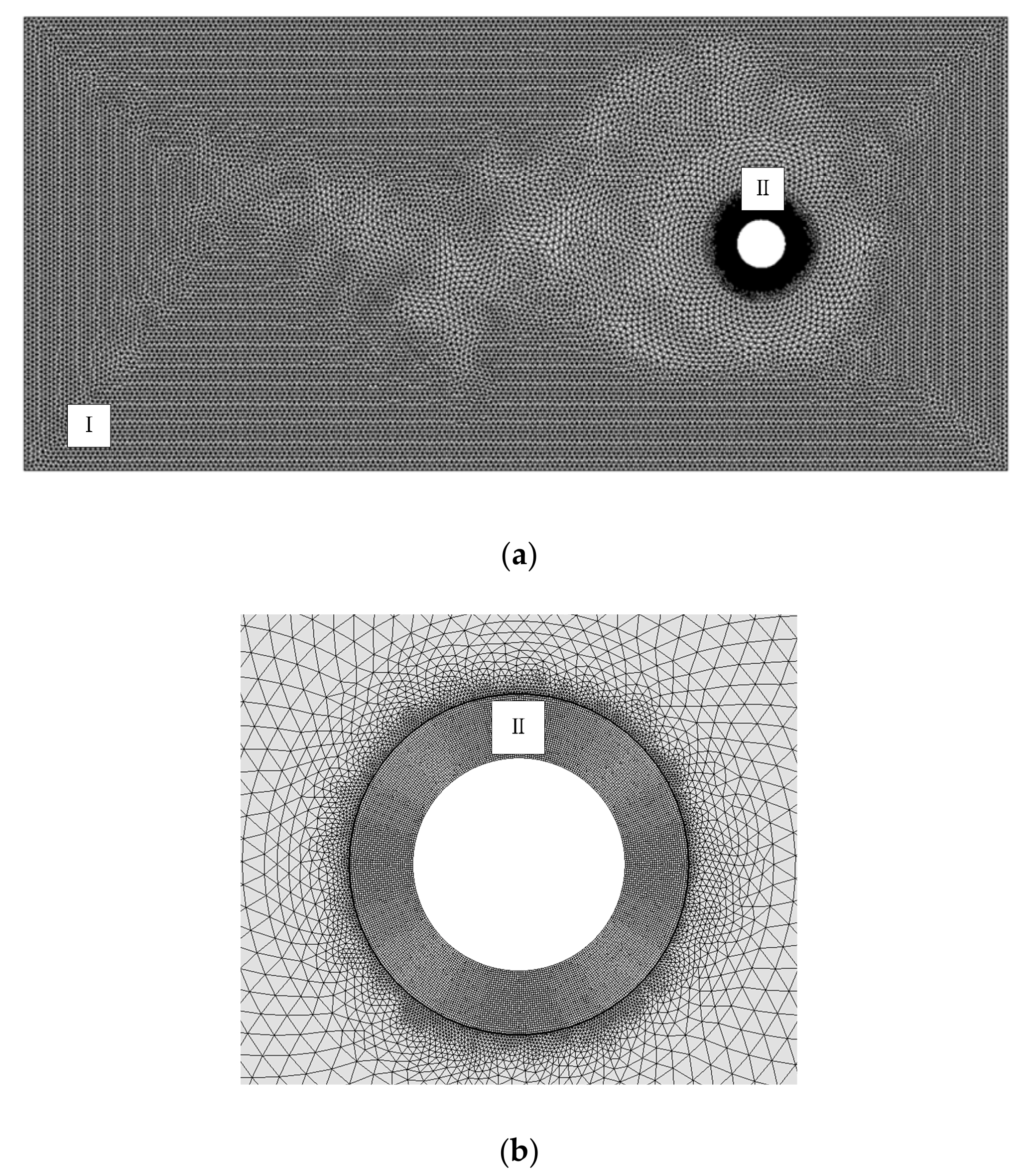
3.4. Computational Mesh
4. Results and Discussions
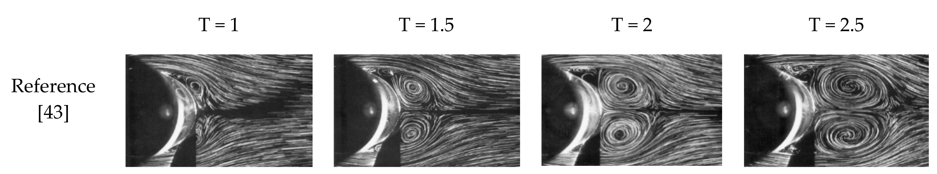
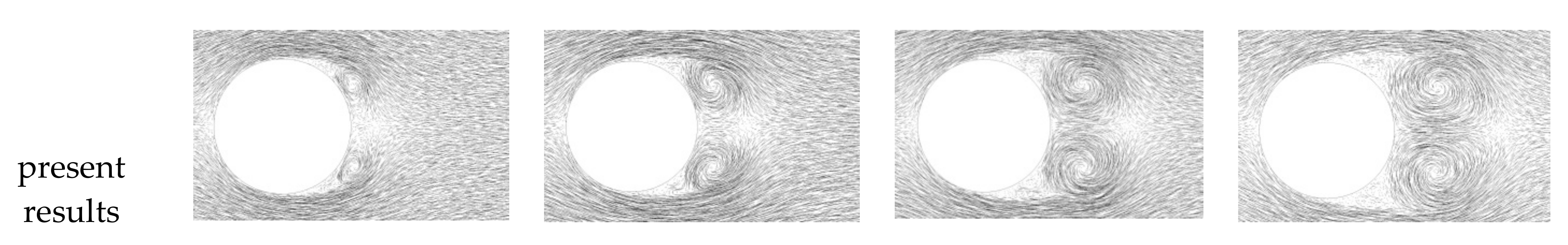
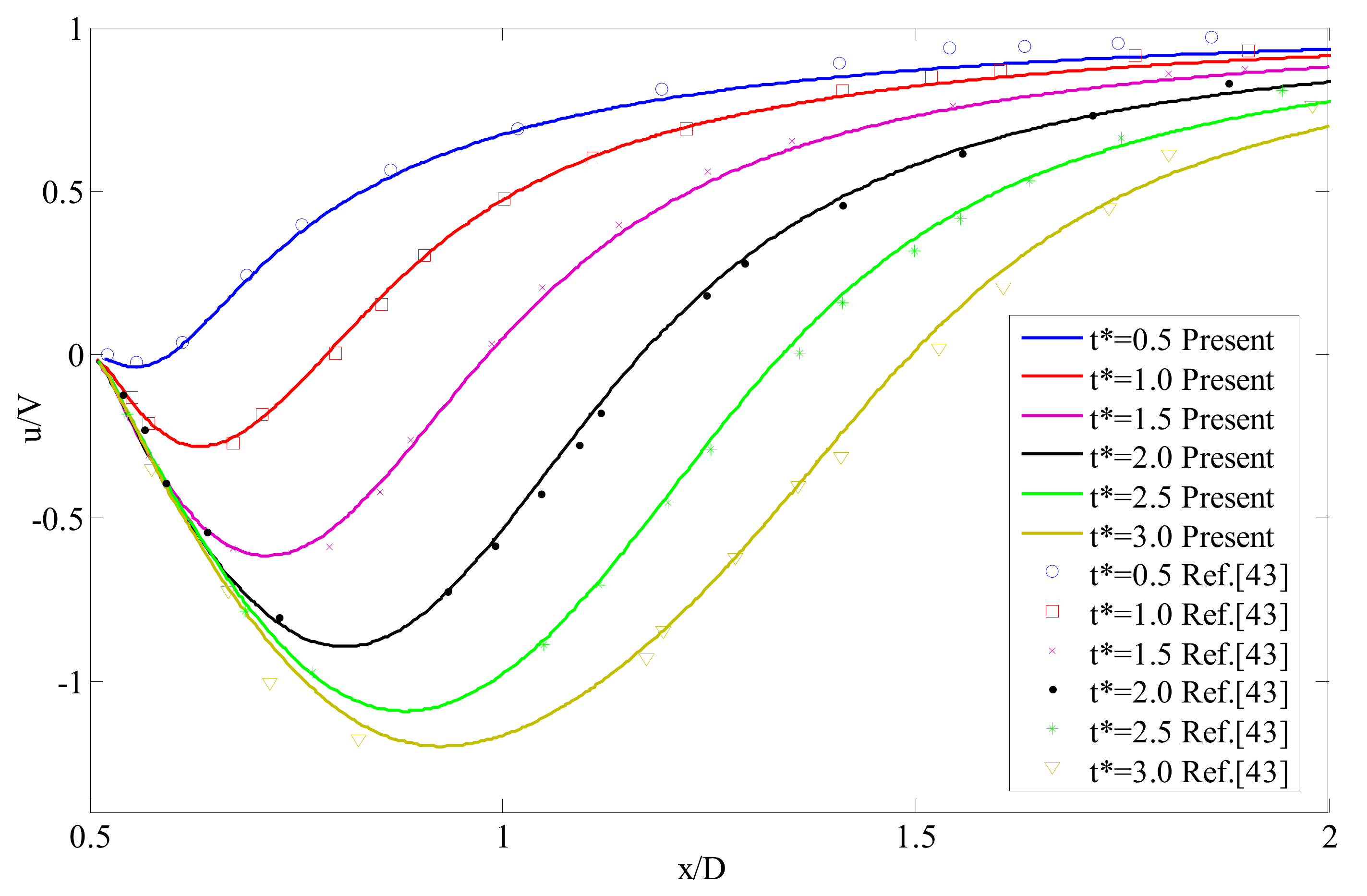
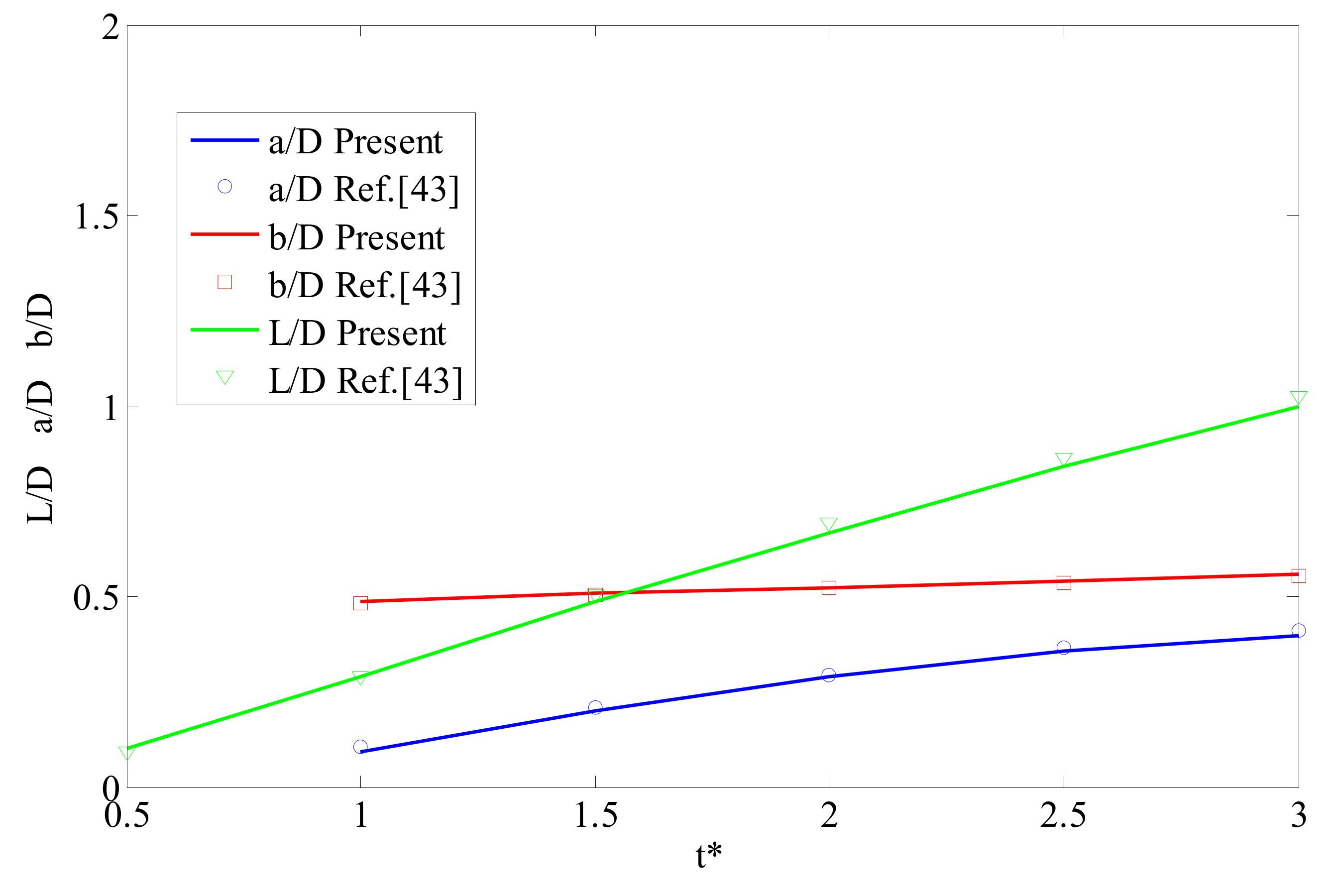
4.1. Models Validation
4.2. Effect of the Locations of Strips
4.3. Effect of The Shapes of Strips
5. Conclusions
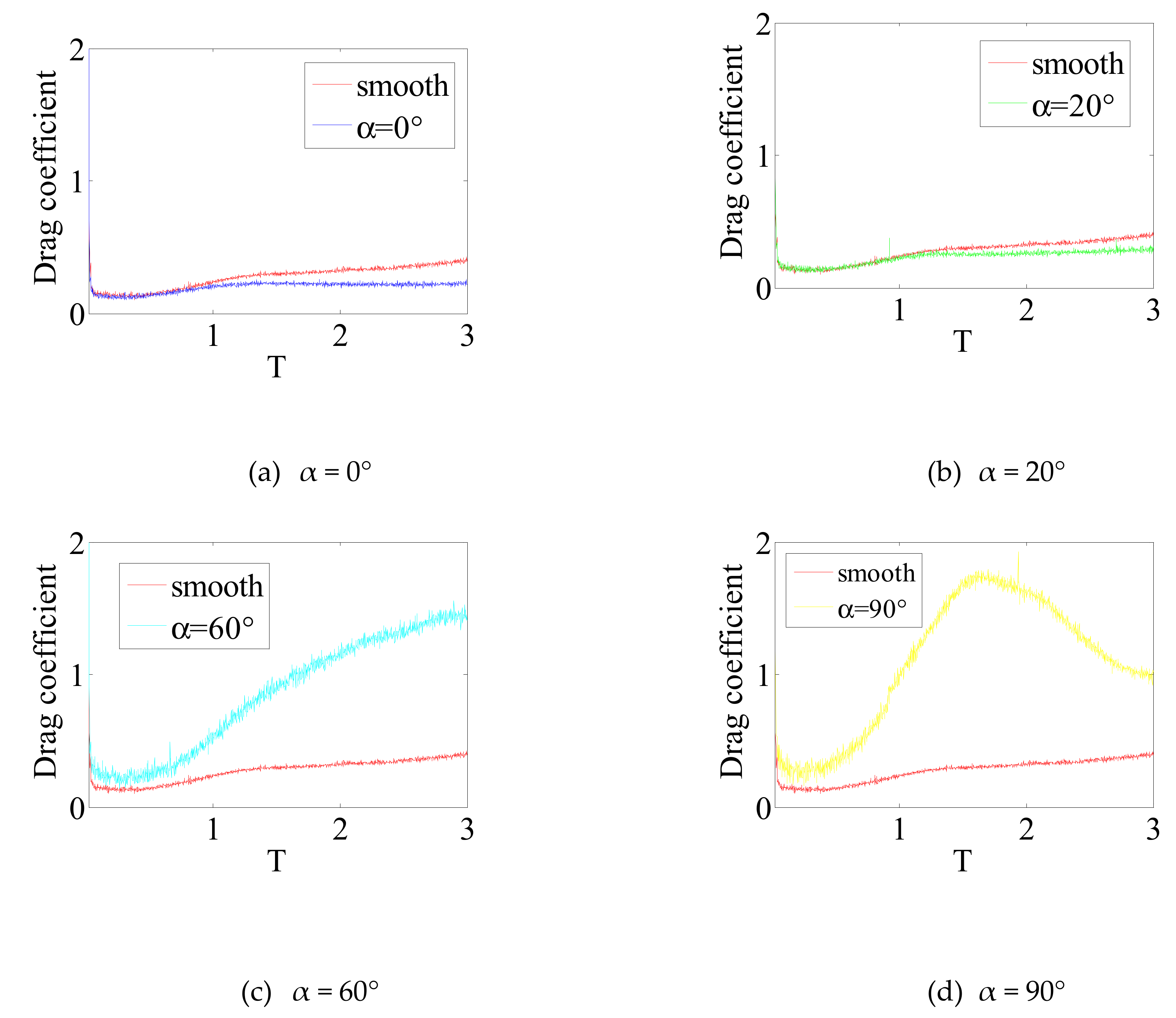
- (1)
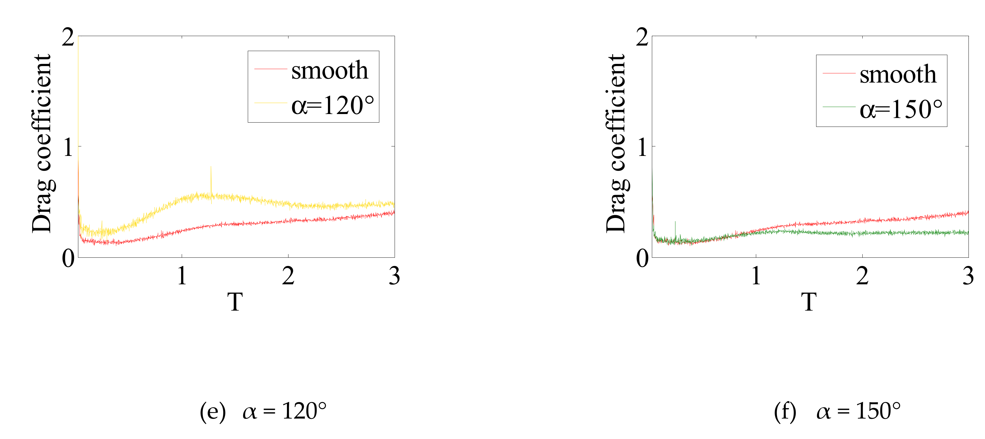
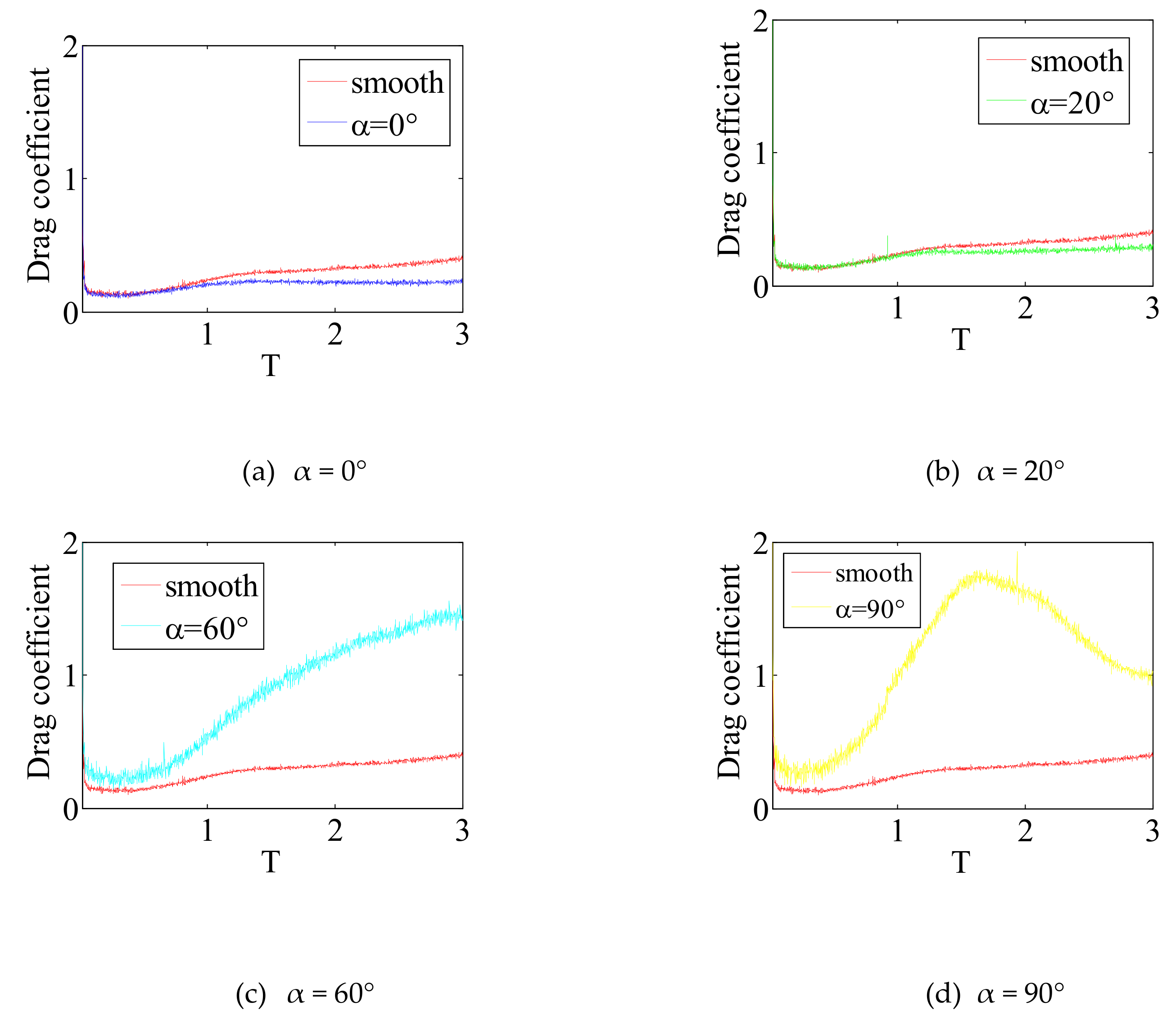
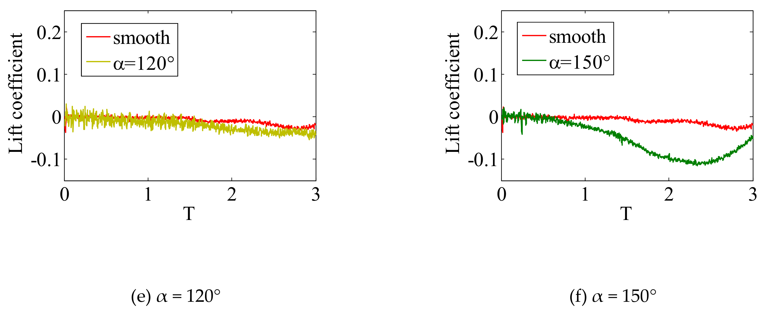
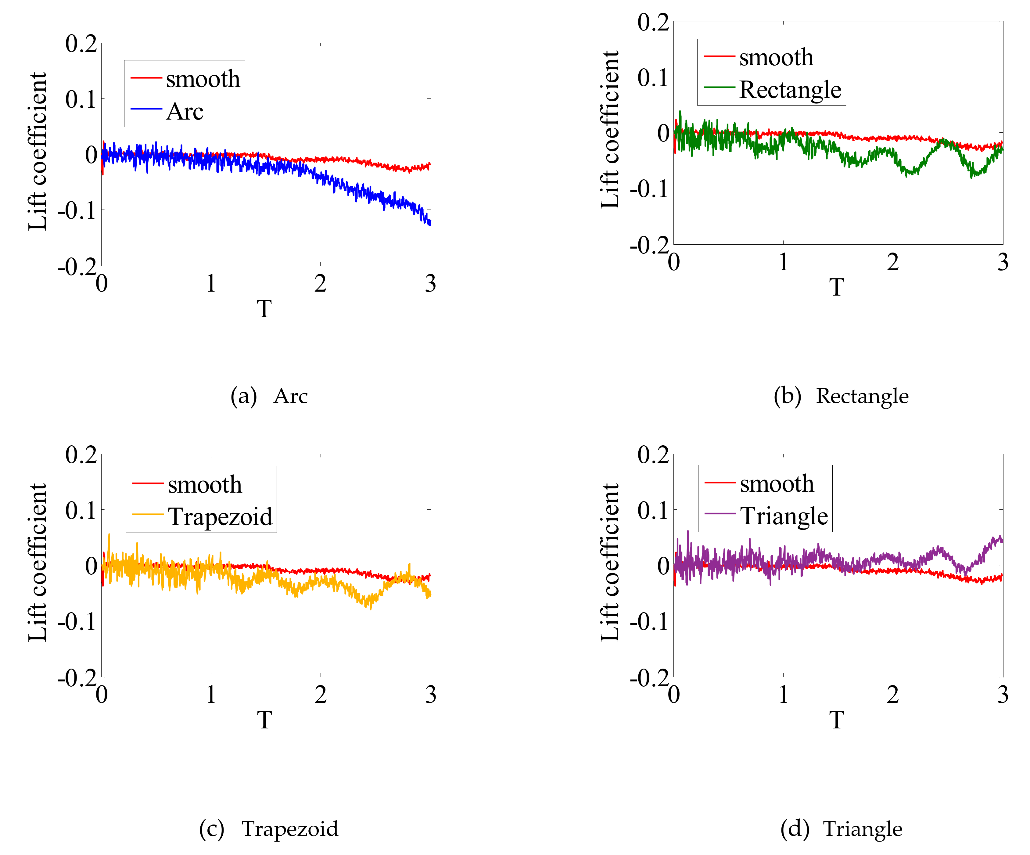
- When the strips are installed near the separation point (α = 90°), where the boundary layer is separated from the cylinder, the effect on the drag coefficient is greater than other locations. Moreover, the maximum of the drag coefficient increased from 0.4 to 1.8, compared with the smooth cylinder. However, it is sensitive to the lift coefficient while the strips are moved near the stagnation point (α = 0°, α = 20° and α = 150°).
- (2)
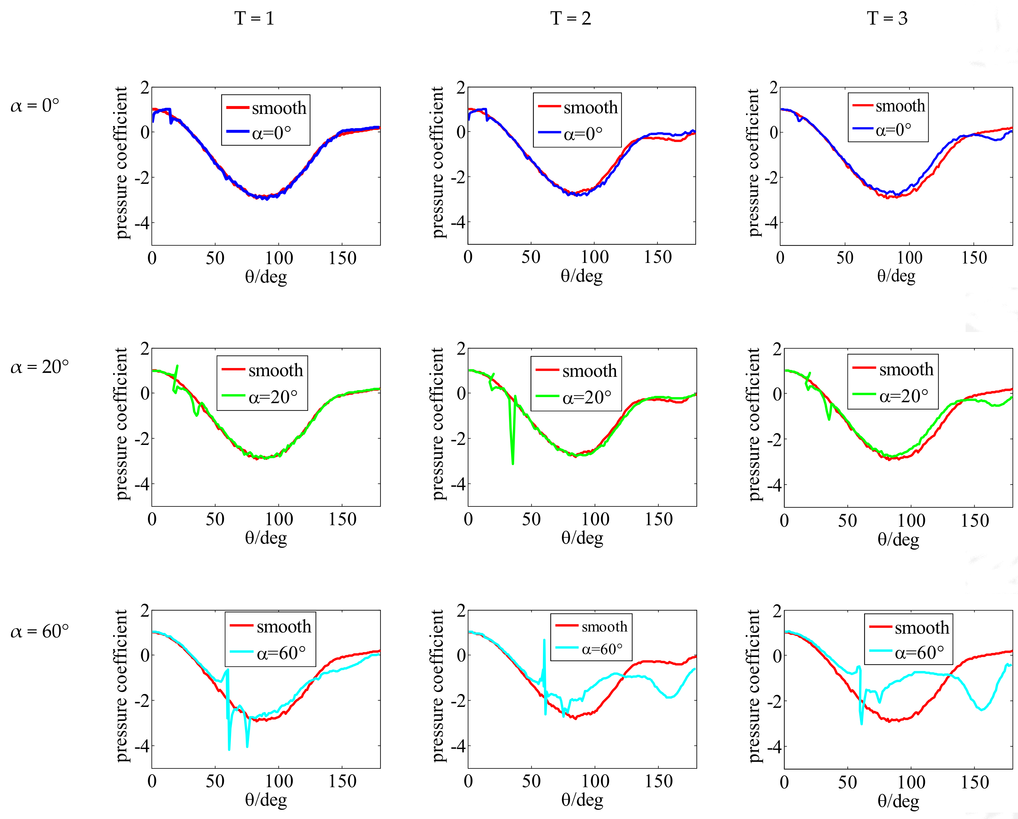
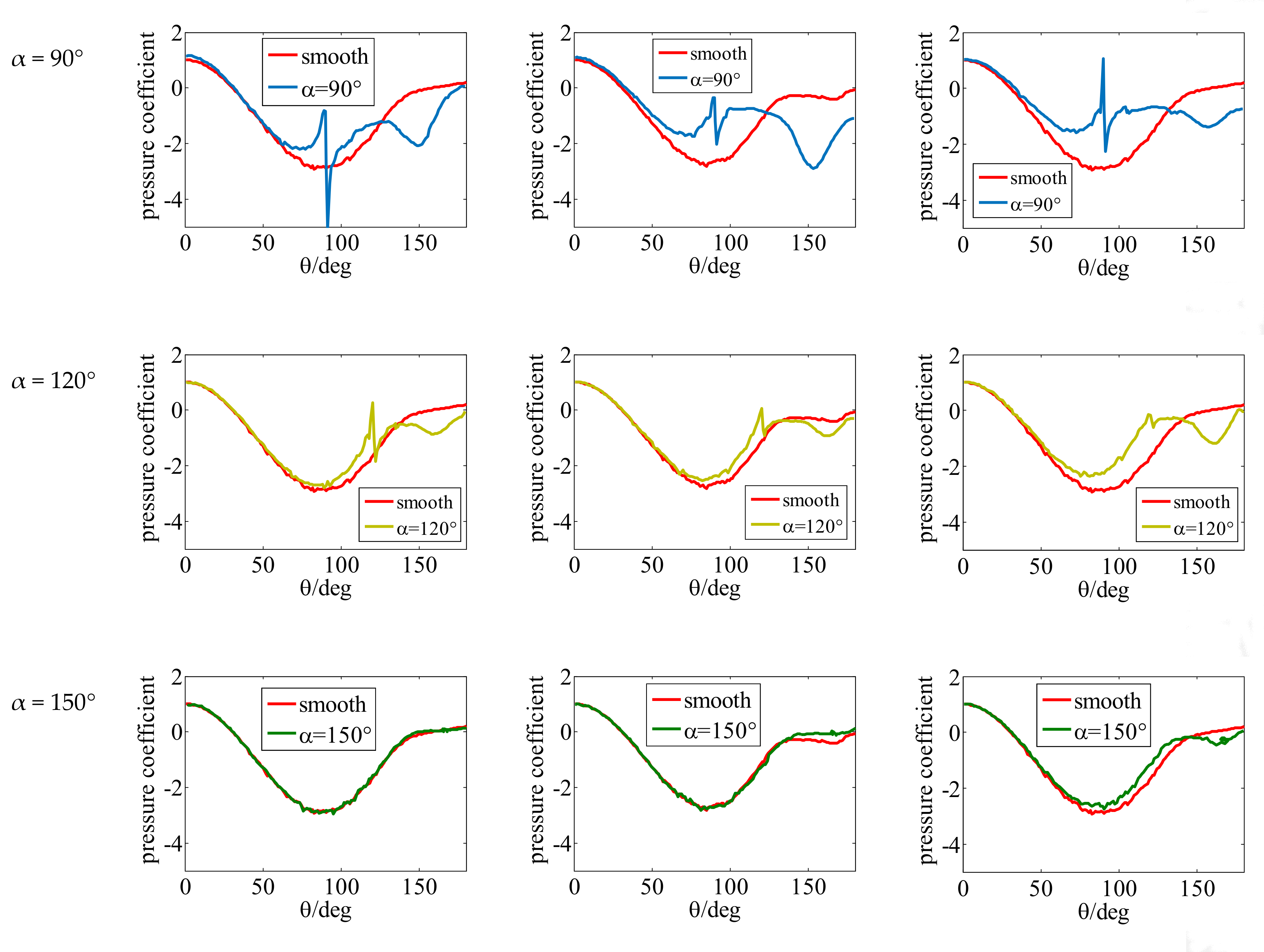
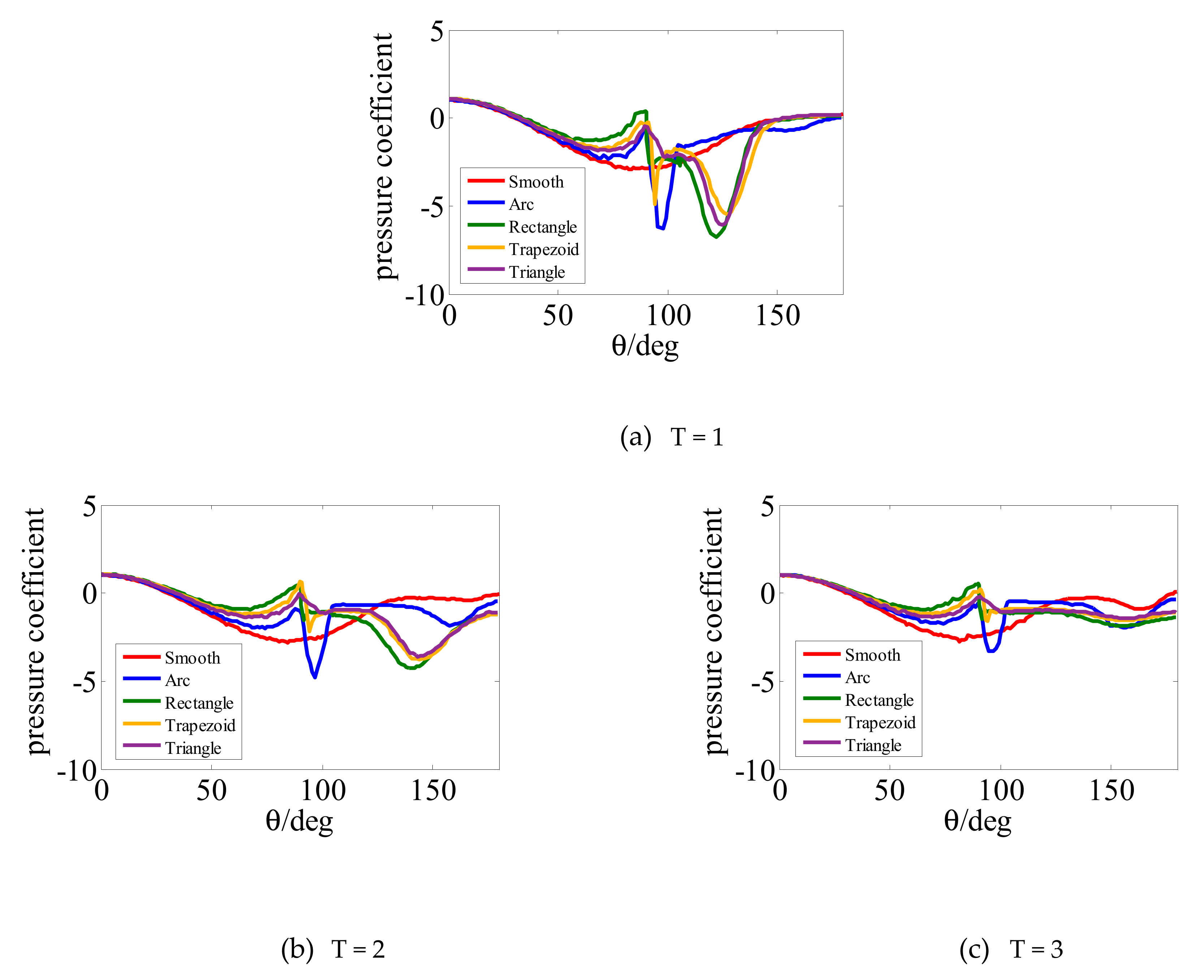
- The disturbance is the largest at α = 90°, when the boundary layer passed through the strips, and the minimum of the pressure coefficients increased by 22.3%, compared to the smooth cylinder at T = 3. When θ varies from 140° to 180°, the pressure coefficient is reduced, except for α = 0°, indicating that the local response of the cylinder could be suppressed by installing strips selectively.
- (3)
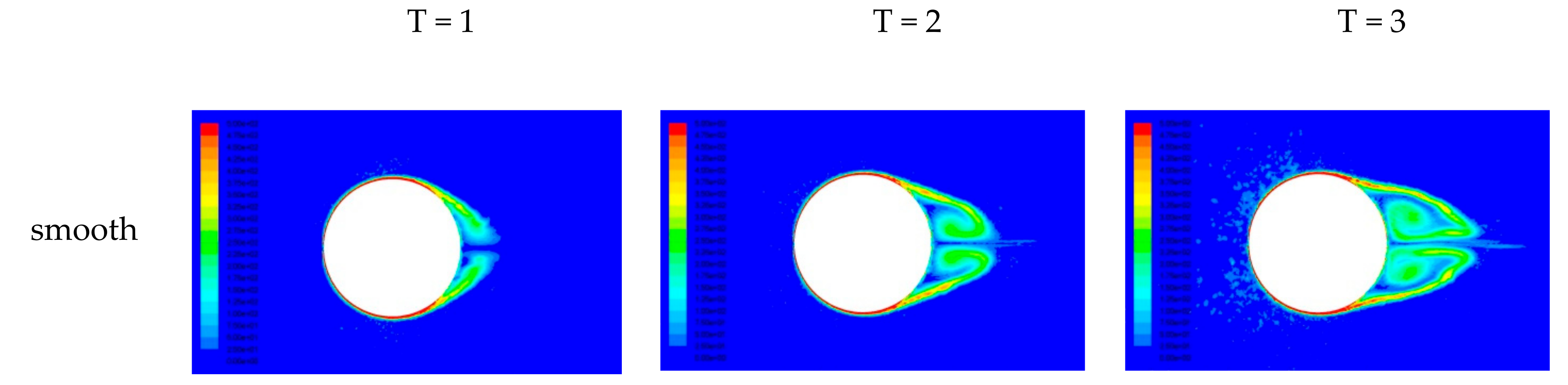
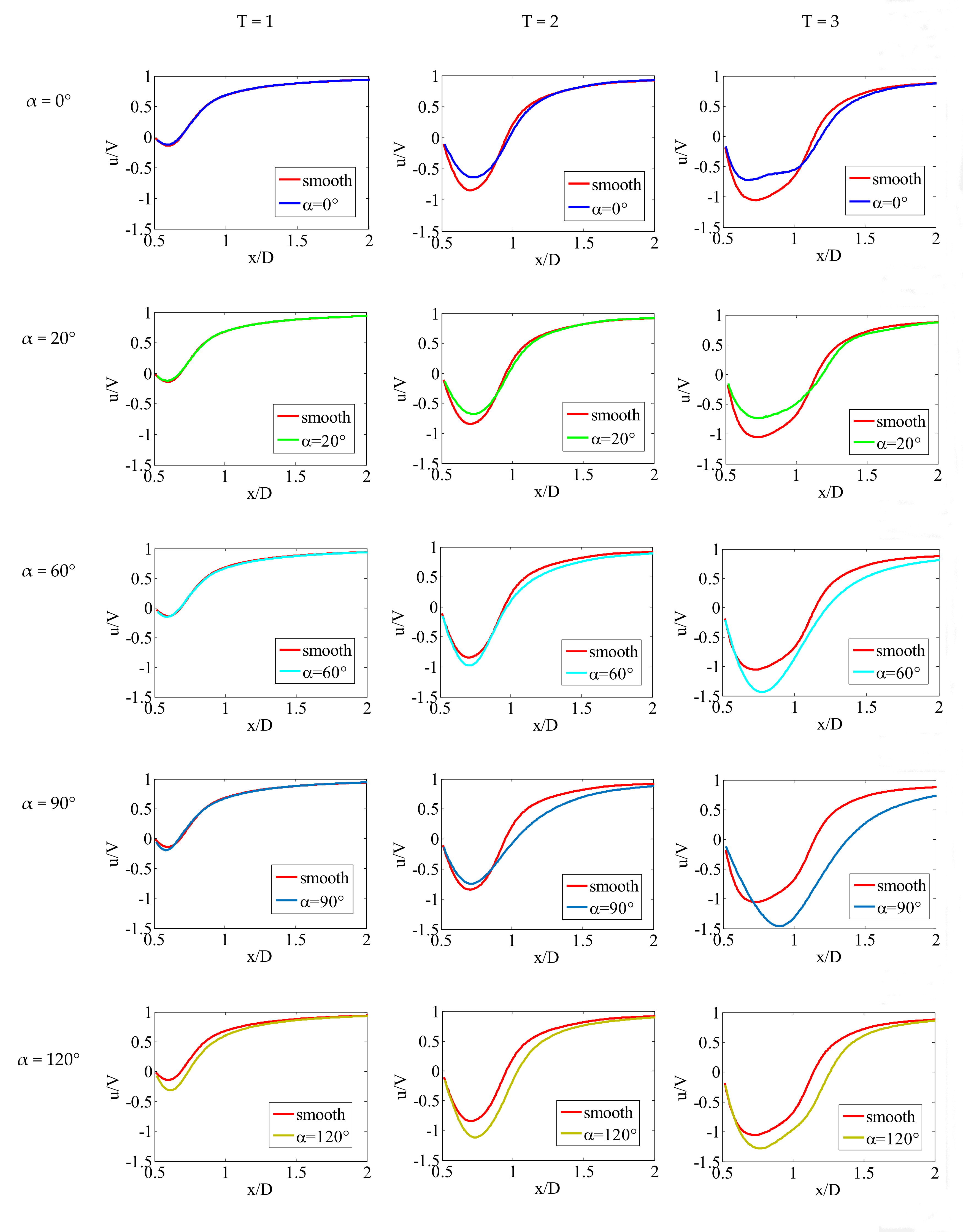
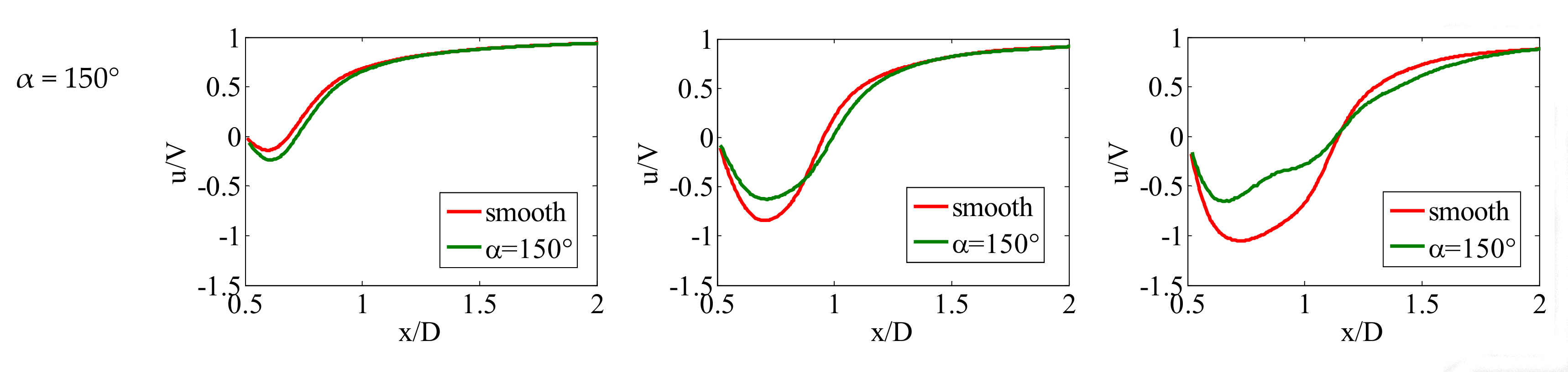
- The installation of strips near the stagnation point can reduce the velocity distribution on the axis, but the installation of strips near the separation point can increase both the velocity distribution on the axis and the length of the wake. When α = 90°, the maximum of negative velocity increased by 38.4%, compared to the smooth cylinder at T = 3.
- (4)
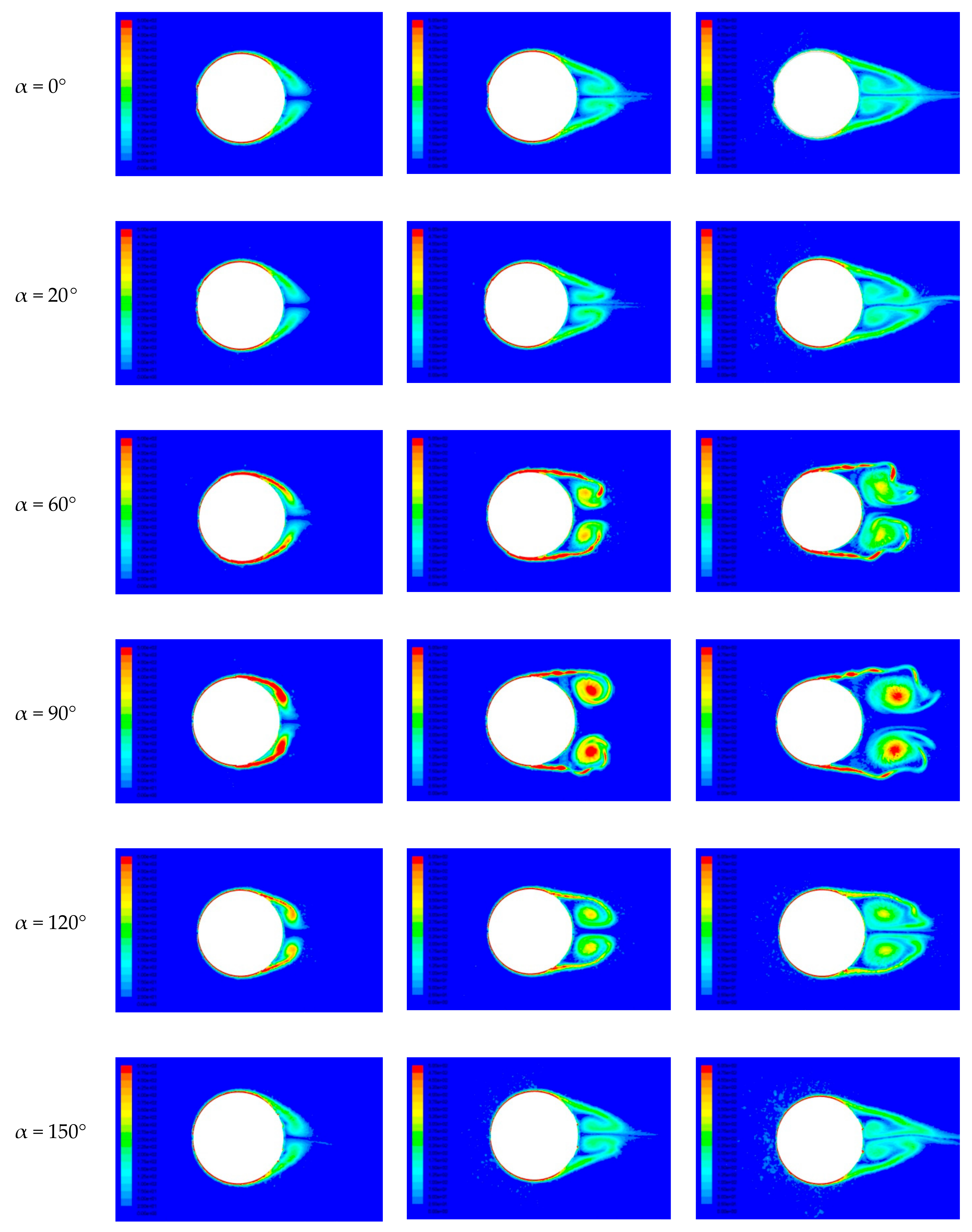
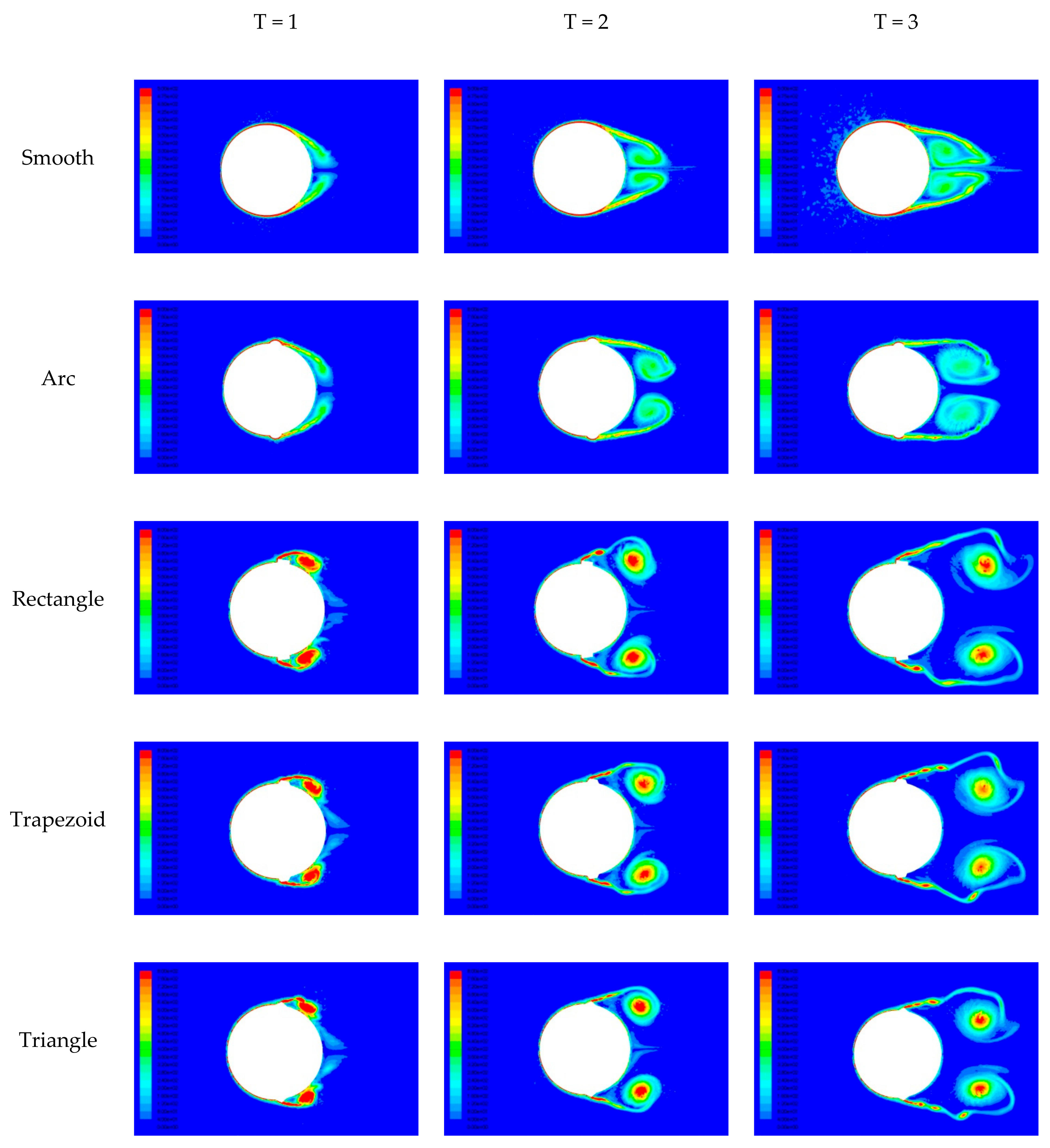
- When the separation point is moved forward due to the installation of the strips, such as α = 60° and α = 90°, the width of the wake increased. While the separation point is moved backward, for example α = 0°, the width of the wake decreased. When the installation position of the strips does not affect the development of the boundary layer, it has little effect on the wake.
- (5)
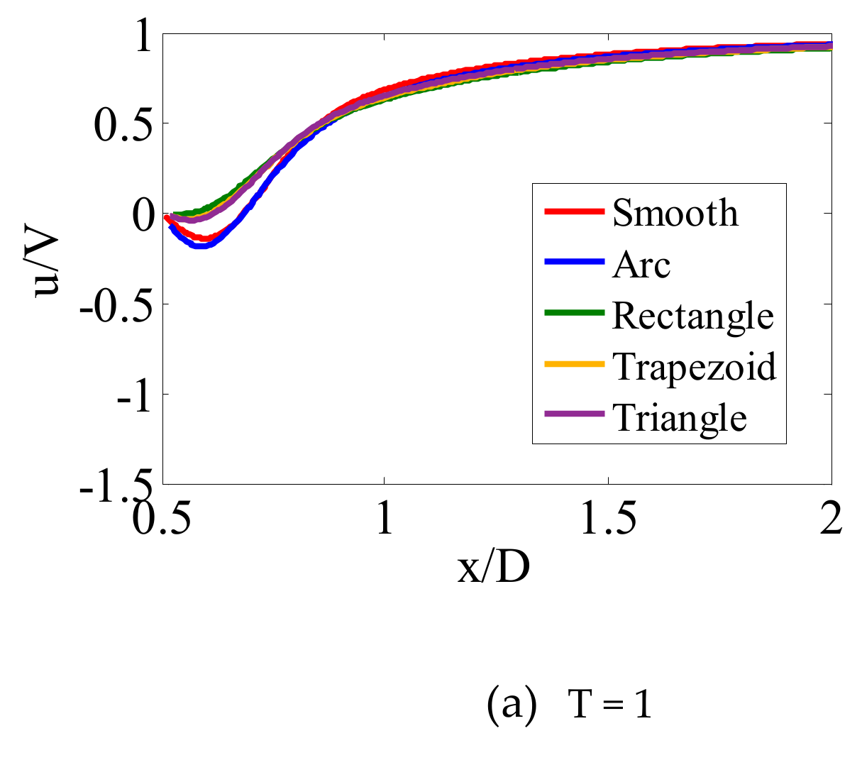
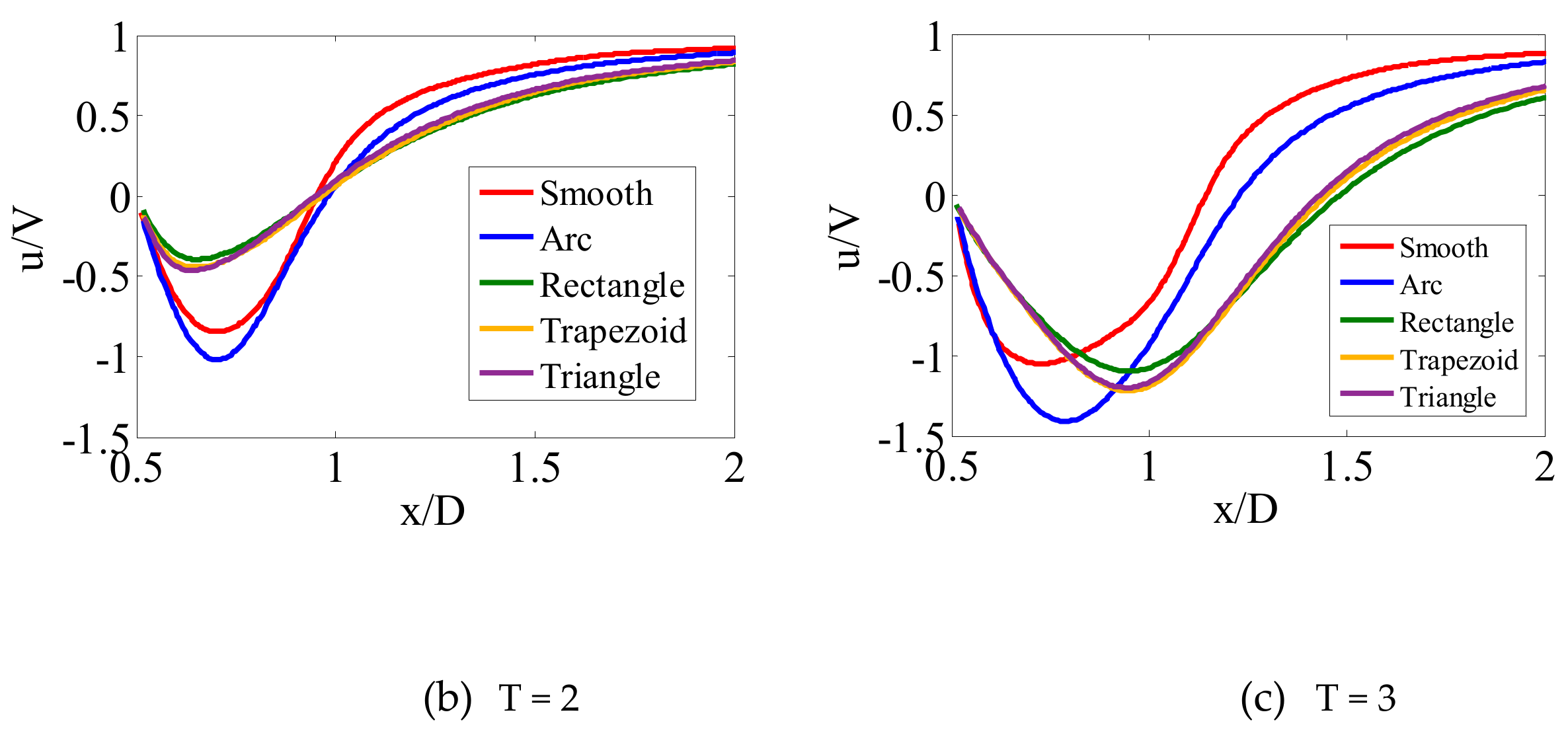
- There was an obvious disturbance when the boundary layer passed through the step (the leading and trailing edges of the strips). The arc-shaped strips have no step, so the effect of the arc-shaped strips is the smallest, and the triangular strips have one step, so the effect is smaller than that of the rectangular strips and the trapezoidal strips with two steps.
Author Contributions
Funding
Acknowledgments
Conflicts of Interest
References
- Gao, W.; Nelias, D.; Liu, Z.; Lyu, Y. Numerical investigation of flow around one finite circular cylinder with two free ends. Ocean Eng. 2018, 156, 373–380. [Google Scholar] [CrossRef]
- Kang, Z.; Zhang, C.; Ma, G.; Ni, W. A numerical investigation of two-degree-of-freedom VIV of a circular cylinder using the modified turbulence model. Ocean Eng. 2018, 155, 211–226. [Google Scholar] [CrossRef]
- Bokaian, A.R.; Geoola, F. Hydroelastic instabilities of square cylinders. J. Sound Vib. 1984, 92, 117–141. [Google Scholar] [CrossRef]
- Da Silva, B.L.; Luciano, R.D.; Utzig, J.; Meier, H.F. Flow patterns and turbulence effects in large cylinder arrays. Int. J. Heat Fluid Flow 2018, 69, 136–149. [Google Scholar] [CrossRef]
- Achenbach, E. Influence of surface roughness on the cross-flow around a circular cylinder. J. Fluid Mech. 1971, 46, 321–335. [Google Scholar] [CrossRef]
- Parkinson, G.V.; Dicker, D. Wind-Induced Instability of Structures [and Discussion]. Philos. Trans. R. Soc. Lond. Ser. A Math. Phys. Sci. 1971, 269, 395–413. [Google Scholar]
- Parkinson, G.V.; Sullivan, P.P. Galloping response of towers. J. Wind. Eng. Ind. Aerodyn. 1979, 4, 253–260. [Google Scholar] [CrossRef]
- Shi, L.; Yang, G.; Yao, S. Large eddy simulation of flow past a square cylinder with rounded leading corners: A comparison of 2D and 3D approaches. J. Mech. Sci. Technol. 2018, 32, 2671–2680. [Google Scholar] [CrossRef]
- Wu, B.; Li, S.; Li, K.; Zhang, L. Numerical and experimental studies on the aerodynamics of a 5:1 rectangular cylinder at angles of attack. J. Wind. Eng. Ind. Aerodyn. 2020, 199, 104097. [Google Scholar] [CrossRef]
- Jiang, F.; Pettersen, B.; Andersson, H.I. Turbulent wake behind a concave curved cylinder. J. Fluid Mech. 2019, 878, 663–699. [Google Scholar] [CrossRef]
- Nakamura, Y.; Hirata, K.; Kashima, K. Galloping of a Circular Cylinder in the Presence of a Splitter Plate. J. Fluids Struct. 1994, 8, 355–365. [Google Scholar] [CrossRef]
- Munir, A.; Zhao, M.; Wu, H.; Ning, D.; Lu, L. Numerical investigation of the effect of plane boundary on two-degree-of-freedom of vortex-induced vibration of a circular cylinder in oscillatory flow. Ocean Eng. 2018, 148, 17–32. [Google Scholar] [CrossRef]
- Bokaian, A.; Geoola, F. Wake-induced galloping of two interfering circular cylinders. J. Fluid Mech. 1984, 146, 383–415. [Google Scholar] [CrossRef]
- Zhu, H.; Gao, Y. Vortex-induced vibration suppression of a main circular cylinder with two rotating control rods in its near wake: Effect of the rotation direction. J. Fluids Struct. 2017, 74, 469–491. [Google Scholar] [CrossRef]
- Zhu, H.; Gao, Y. Effect of gap on the vortex-induced vibration suppression of a circular cylinder using two rotating rods. Ships Offshore Struct. 2017, 13, 119–131. [Google Scholar] [CrossRef]
- Zhu, H.; Yao, J. Numerical evaluation of passive control of VIV by small control rods. Appl. Ocean Res. 2015, 51, 93–116. [Google Scholar] [CrossRef]
- Zhu, H.; Yao, J.; Ma, Y.; Zhao, H.; Tang, Y. Simultaneous CFD evaluation of VIV suppression using smaller control cylinders. J. Fluids Struct. 2015, 57, 66–80. [Google Scholar] [CrossRef]
- Liu, C.; Gao, Y.; Qu, X.-C.; Wang, B.; Zhang, B.-F. Numerical Simulation on Flow Past Two Side-by-Side Inclined Circular Cylinders at Low Reynolds Number. China Ocean Eng. 2019, 33, 344–355. [Google Scholar] [CrossRef]
- Choi, H.; Jeon, W.-P.; Kim, J. Control of Flow Over a Bluff Body. Annu. Rev. Fluid Mech. 2008, 40, 113–139. [Google Scholar] [CrossRef]
- Zhou, X.; Wang, J.; Hu, Y. Experimental investigation on the flow around a circular cylinder with upstream splitter plate. J. Vis. 2019, 22, 683–695. [Google Scholar] [CrossRef]
- Kim, S.; Alam, M.; Maiti, D.K. Wake and suppression of flow-induced vibration of a circular cylinder. Ocean Eng. 2018, 151, 298–307. [Google Scholar] [CrossRef]
- Achenbach, E.; Heinecke, E. On vortex shedding from smooth and rough cylinders in the range of Reynolds numbers 6×10³ to 5×10⁶. J. Fluid Mech. 1981, 109, 239–251. [Google Scholar] [CrossRef]
- Güven, O.; Farell, C.; Patel, V.C. Surface-roughness effects on the mean flow past circular cylinders. J. Fluid Mech. 1980, 98, 673–701. [Google Scholar] [CrossRef]
- Nakamura, Y.; Tomonari, Y. The effects of surface roughness on the flow past circular cylinders at high Reynolds numbers. J. Fluid Mech. 1982, 123, 363–378. [Google Scholar] [CrossRef]
- Shih, W.C.L.; Wang, C.; Coles, D.; Roshko, A. Experiments on flow past rough circular cylinders at large Reynolds numbers. J. Wind. Eng. Ind. Aerodyn. 1993, 49, 351–368. [Google Scholar] [CrossRef]
- Hover, F.S.; Tvedt, H.; Triantafyllou, M.S. Vortex-induced vibrations of a cylinder with tripping wires. J. Fluid Mech. 2001, 448, 175–195. [Google Scholar] [CrossRef]
- Zdravkovich, M.M. Flow Around Circular Cylinders. Fundamentals; Oxford Science Publications: Oxford, UK, 1997; pp. 566–571. [Google Scholar]
- Zhu, H.; Zhou, T. Flow around a circular cylinder attached with a pair of fin-shaped strips. Ocean Eng. 2019, 190, 106484. [Google Scholar] [CrossRef]
- Sun, H.; Bernitsas, M.M.; Turkol, M. Adaptive harnessing damping in hydrokinetic energy conversion by two rough tandem-cylinders using flow-induced vibrations. Renew. Energy 2020, 149, 828–860. [Google Scholar] [CrossRef]
- Park, H.; Kumar, R.A.; Bernitsas, M.M. Enhancement of flow-induced motion of rigid circular cylinder on springs by localized surface roughness at 3×10⁴≤Re≤1.2×10⁵. Ocean Eng. 2013, 72, 403–415. [Google Scholar] [CrossRef]
- Park, H.; Bernitsas, M.M.; Kim, E.S. Selective Surface Roughness to Suppress Flow-Induced Motion of Two Circular Cylinders at 30,000 <Re <120,000. J. Offshore Mech. Arct. Eng. 2014, 136, 041804–041806. [Google Scholar]
- Bernitsas, M.M.; Ben-Simon, Y.; Raghavan, K.; Garcia, E.M.H. The VIVACE Converter: Model Tests at High Damping and Reynolds Number Around 105. J. Offshore Mech. Arct. Eng. 2008, 131, 011102–011112. [Google Scholar] [CrossRef]
- Bernitsas, M.M.; Raghavan, K.; Ben-Simon, Y.; Garcia, E.M.H. VIVACE (Vortex Induced Vibration Aquatic Clean Energy): A New Concept in Generation of Clean and Renewable Energy from Fluid Flow. J. Offshore Mech. Arct. Eng. 2008, 130, 041101–041115. [Google Scholar] [CrossRef]
- Bernitsas, M.M.; Raghavan, K. Reduction/Suppression of VIV of Circular Cylinders Through Roughness Distribution at 8×10³ < Re < 1.5×10⁵. In Proceedings of the ASME 2008 27th International Conference on Offshore Mechanics and Arctic Engineering, Estoril, Portugal, 15–20 June 2008; pp. 1001–1005. [Google Scholar]
- Raghavan, K.; Bernitsas, M.M. Experimental investigation of Reynolds number effect on vortex induced vibration of rigid circular cylinder on elastic supports. Ocean Eng. 2011, 38, 719–731. [Google Scholar] [CrossRef]
- Raghavan, K.; Bernitsas, M.M. Enhancement of High Damping VIV Through Roughness Distribution for Energy Harnessing at 8×10³ < Re < 1.5×10⁵. In Proceedings of the ASME 2008 27th International Conference on Offshore Mechanics and Arctic Engineering, Estoril, Portugal, 15–20 June 2008; pp. 871–882. [Google Scholar]
- Quadrante, L.A.R.; Nishi, Y. Amplification/suppression of flow-induced motions of an elastically mounted circular cylinder by attaching tripping wires. J. Fluids Struct. 2014, 48, 93–102. [Google Scholar] [CrossRef]
- Zhu, H.; Gao, Y.; Zhou, T. Flow-induced vibration of a locally rough cylinder with two symmetrical strips attached on its surface: Effect of the location and shape of strips. Appl. Ocean Res. 2018, 72, 122–140. [Google Scholar] [CrossRef]
- Vinod, A.; Auvil, A.; Banerjee, A. On passive control of transition to galloping of a circular cylinder undergoing vortex induced vibration using thick strips. Ocean Eng. 2018, 163, 223–231. [Google Scholar] [CrossRef]
- Vinod, A.; Banerjee, A. Surface protrusion based mechanisms of augmenting energy extraction from vibrating cylinders at Reynolds number 3 × 10³–3 × 10⁴. J. Renew. Sustain. Energy 2014, 6, 063106. [Google Scholar] [CrossRef]
- Chang, C.-C.; Kumar, R.A.; Bernitsas, M.M. VIV and galloping of single circular cylinder with surface roughness at 3.0×10⁴≤Re≤1.2×10⁵. Ocean Eng. 2011, 38, 1713–1732. [Google Scholar] [CrossRef]
- Coutanceau, M.; Ménard, C. Influence of rotation on the near-wake development behind an impulsively started circular cylinder. J. Fluid Mech. 1985, 158, 399–446. [Google Scholar] [CrossRef]
- Bouard, R.; Coutanceau, M. The early stage of development of the wake behind an impulsively started cylinder for 40 <Re <104. J. Fluid Mech. 1980, 101, 583–607. [Google Scholar]
- Afra, B.; Nazari, M.; Kayhani, M.H.; Delouei, A.A.; Ahmadi, G. An immersed boundary-lattice Boltzmann method combined with a robust lattice spring model for solving flow–structure interaction problems. Appl. Math. Model. 2018, 55, 502–521. [Google Scholar] [CrossRef]
- Liska, S.; Colonius, T. A fast immersed boundary method for external incompressible viscous flows using lattice Green’s functions. J. Comput. Phys. 2017, 331, 257–279. [Google Scholar] [CrossRef]
- Spotz, W.F.; Carey, G.F. Extension of high-order compact schemes to time-dependent problems. Numer. Methods Partial. Differ. Equations 2001, 17, 657–672. [Google Scholar] [CrossRef]
- Coutanceau, M.; Bouard, R. Experimental determination of the main features of the viscous flow in the wake of a circular cylinder in uniform translation. Part 2. Unsteady flow. J. Fluid Mech. 1977, 79, 257–272. [Google Scholar] [CrossRef]
- Coutanceau, M.; Bouard, R. Experimental determination of the main features of the viscous flow in the wake of a circular cylinder in uniform translation. Part 1. Steady flow. J. Fluid Mech. 1977, 79, 231–256. [Google Scholar] [CrossRef]
- Collins, W.M.; Dennis, S.C.R. Flow past an impulsively started circular cylinder. J. Fluid Mech. 1973, 60, 105–127. [Google Scholar] [CrossRef]
- Chen, Y.-M.; Ou, Y.-R.; Pearlstein, A.J. Development of the wake behind a circular cylinder impulsively started into rotatory and rectilinear motion. J. Fluid Mech. 1993, 253, 449–484. [Google Scholar] [CrossRef]
- Demirdžić, I.; Perić, M. Finite volume method for prediction of fluid flow in arbitrarily shaped domains with moving boundaries. Int. J. Numer. Methods Fluids 1990, 10, 771–790. [Google Scholar] [CrossRef]
- Koobus, B.; Farhat, C. Second-order time-accurate and geometrically conservative implicit schemes for flow computations on unstructured dynamic meshes. Comput. Methods Appl. Mech. Eng. 1999, 170, 103–129. [Google Scholar] [CrossRef]
- Patankar, S.V. Numerical Heat Transfer and Fluid Flow; McGraw Hill: New York, NY, USA, 1980. [Google Scholar]
- Kinzel, M.P.; Lindau, J.W.; Kunz, R.F. Free-Surface Proximity Effects in Developed and Super-Cavitation. In Proceedings of the 2008 DoD HPCMP Users Group Conference, Seattle, WA, USA, 14–17 July 2008; IEEE Computer Society: New York, NY, USA, 2008; pp. 25–34. [Google Scholar]
- Kinzel, M.P. Computational Techniques and Analysis of Cavitating-Fluid Flows. Ph.D. Thesis, Pennsylvania State University, State College, PA, USA, 2008. [Google Scholar]
- Kim, S.E.A. Numerical Study of Unsteady Cavitation on a Hydrofoil. In Proceedings of the Seventh International Symposium on Cavitation, CAV 2009, Ann-Arbor, MI, USA, 16–20 August 2009. [Google Scholar]
- Qin, Q.; Song, C.C.S.; Arndt, R.E.A. Numerical Study of an Unsteady Turbulent Wake behind a Cavitating Hydrofoil. In Proceedings of the Fifth International Symposium on Cavitation (CAV03-GS-9-001), Osaka, Japan, 1–4 November 2003. [Google Scholar]
- Qin, Q.; Song, C.C.S.; Arndt, R.E.A. Incondensable Gas Effect on Turbulent Wake behind a Cavitating Hydrofoil. In Proceedings of the Fifth International Symposium on Cavitation (CAV03-GS-9-001), Osaka, Japan, 1–4 November 2003. [Google Scholar]
- Arndt, R.E.A. From Wageningen to Minnesota and back: Perspectives on Cavitation Research. In Proceedings of the Sixth International Symposium on Cavitation (CAV2006), Wageningen, The Netherlands, 11–14 September 2006. [Google Scholar]


| Initial Nm | Min Length Scale (mm) | Max Length Scale (mm) | Final Nm | CD | CL |
|---|---|---|---|---|---|
| 19,452 | 6 | 8 | 22,072 | 0.311 | 0.0201 |
| 31,247 | 4 | 6 | 38,763 | 0.341(9.65%) | 0.0229(13.93%) |
| 40,256 | 2 | 4 | 102,856 | 0.368(7.92%) | 0.0245(6.99%) |
| 52,436 | 1.5 | 2 | 308,643 | 0.387(5.16%) | 0.0258(5.31%) |
| 60,711 | 0.8 | 1.2 | 956,754 | 0.389(0.52%) | 0.0261(1.16%) |
| Δt | CD | CL |
|---|---|---|
| 0.005 s | 0.271 | 0.0183 |
| 0.001 s | 0.312(15.13%) | 0.0209(14.21%) |
| 0.0005 s | 0.349(11.86%) | 0.0231(10.53%) |
| 0.0002 s | 0.371(6.30%) | 0.0249(7.79%) |
| 0.0001 s | 0.387(4.31%) | 0.0258(3.61%) |
© 2020 by the authors. Licensee MDPI, Basel, Switzerland. This article is an open access article distributed under the terms and conditions of the Creative Commons Attribution (CC BY) license (http://creativecommons.org/licenses/by/4.0/).
Share and Cite
Zhou, J.; Jin, G.; Ye, T.; Wang, K.; Sun, K. The Transient Flow behind an Instantaneously Started Circular Cylinder with Two Symmetrical Strips. Appl. Sci. 2020, 10, 2308. https://doi.org/10.3390/app10072308
Zhou J, Jin G, Ye T, Wang K, Sun K. The Transient Flow behind an Instantaneously Started Circular Cylinder with Two Symmetrical Strips. Applied Sciences. 2020; 10(7):2308. https://doi.org/10.3390/app10072308
Chicago/Turabian StyleZhou, Jialiang, Guoyong Jin, Tiangui Ye, Kai Wang, and Kailang Sun. 2020. "The Transient Flow behind an Instantaneously Started Circular Cylinder with Two Symmetrical Strips" Applied Sciences 10, no. 7: 2308. https://doi.org/10.3390/app10072308
APA StyleZhou, J., Jin, G., Ye, T., Wang, K., & Sun, K. (2020). The Transient Flow behind an Instantaneously Started Circular Cylinder with Two Symmetrical Strips. Applied Sciences, 10(7), 2308. https://doi.org/10.3390/app10072308