Article

Development of an Experimental Platform for Combinative Use of an XFEL and a High-Power Nanosecond Laser

1
Japan Synchrotron Radiation Research Institute, 1-1-1 Kouto, Sayo-cho, Sayo-gun, Hyogo 679-5198, Japan
2
RIKEN SPring-8 Center, 1-1-1 Kouto, Sayo-cho, Sayo-gun, Hyogo 679-5148, Japan
3
Graduate School of Engineering, Osaka University, Suita, Osaka 565-0871, Japan Yamada-oka, Suita, Osaka 565-0871, Japan
4
Institute of Laser Engineering, Osaka University, Suita, Osaka 565-0871, Japan Yamada-oka, Suita, Osaka 565-0871, Japan
*
Author to whom correspondence should be addressed.
Appl. Sci. 2020, 10(7), 2224; https://doi.org/10.3390/app10072224
Submission received: 1 March 2020 / Revised: 13 March 2020 / Accepted: 17 March 2020 / Published: 25 March 2020
(This article belongs to the Special Issue Science at X-ray Free Electron Lasers)

Abstract

:
We developed an experimental platform for combinative use of an X-ray free electron laser (XFEL) and a high-power nanosecond laser. The main target of the platform is an investigation of matter under high-pressure states produced by a laser-shock compression. In this paper, we show details of the experimental platform, including XFEL parameters and the focusing optics, the laser irradiation system and X-ray diagnostics. As a demonstration of the high-power laser-pump XFEL-probe experiment, we performed an X-ray diffraction measurement. An in-situ single-shot X-ray diffraction pattern expands to a large angle side, which shows a corundum was compressed by laser irradiation.

1. Introduction

X-ray free electron lasers (XFELs) [1,2,3,4,5] open up new scientific frontiers in various fields [6,7,8,9]. In particular, high-pressure science combining high-power laser-shock compression and single-shot probing with an XFEL pulse is expected to enable observation of matters in an extreme condition. In typical high-pressure experiments at conventional synchrotron light sources, static high-pressure states, which are generated with, for example, a diamond anvil cell, are probed by accumulation of multiple X-ray pulses [10,11]. In contrast, single-shot measurement is applicable with an XFEL sources owing to plenty photon numbers included in a single XFEL pulse. Moreover, the short pulse duration enables to obtain a snapshot with the time resolution better than 10 fs [12,13]. Therefore, instantaneous ultrahigh-pressure states generated with high-power laser irradiation can be investigated with XFEL.
For this purpose, experimental systems for the combination of XFEL and high-power laser have been developed at the Linac Coherent Light Source [14] and the European XFEL [15]. In the SPring-8 Angstrom Compact Free Electron Laser (SACLA), a prototypical experimental system was utilized for observing lattice dynamics in a tantalum foil irradiated with a 1-J class sub-nanosecond laser [16]. Recently, we have installed a 100-J class nanosecond laser so as to reach a higher-pressure region. Here we report the development of a new experimental platform for combinative use of XFEL and the 100-J class laser in SACLA.

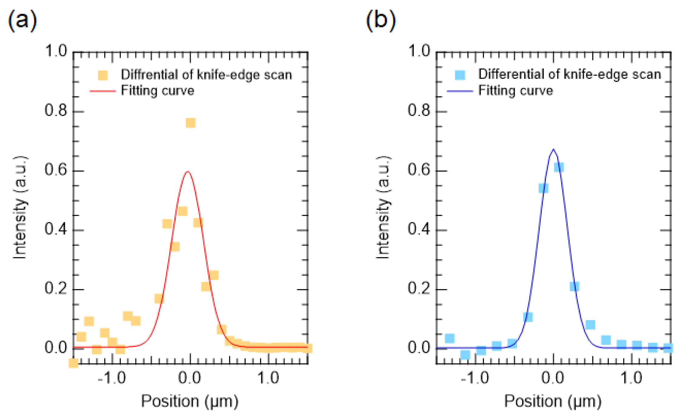
2. XFEL and Focusing Optics

The experimental platform was installed at BL3-EH5, which is 200-m far from the exit of the last undulator [2,17]. At BL3, XFEL pulses are normally generated by a self-amplified spontaneous emission (SASE) scheme [18,19]. The photon energy ranges from 4 to 20 keV with a pulse duration of around 8 fs in full width at half maximum (FWHM) in horizontal polarization [12,13]. The bandwidth (ΔE/E) can be selected from two operation modes: a pink and monochromatic beam. The pink beam, which preserves the original SASE-XFEL spectrum, has the bandwidth of ~5 × 10⁻³ and provides the largest photon number in the all operation modes, which is more than 1011 photons/pulse. The spectrum of SASE-XFEL has many spike structures which change shot-by-shot. A single-shot spectrometer installed at EH1, which is an upstream experimental hutch of the EH5, is available for data correction to compensate an influence caused by shot-by-shot spectral changes [20]. A monochromatic beam with the bandwidth of ~1 × 10⁻⁴ is made by a double-crystal monochromator (DCM) using two silicon (111) crystals. The photon number decreases proportional to the narrowing of the bandwidth. In addition to these two basic operation modes, a self-seeded XFEL operation has been achieved for generating a bright quasi-monochromatic beam [21]. Moreover, two-color XFEL, which produces two XFEL pulses of different energies with a delay time up to 300 fs, is also available [22].
In order to obtain an intense signal and a high signal-to-noise ratio, an XFEL pulse with a high photon flux should illuminate a limited area inside a pumped region by irradiation of a high-power laser pulse. For this purpose, a Kirkpatrick-Baez (KB) optics was installed for sub-micron focusing of XFEL. A large convergence angle of X-rays degrades a resolution of XRD measurement. Therefore, in order to avoid the degradation, the vertical convergence angle of the focused XFEL was suppressed to less than 1 mrad. As shown in Figure 1, the vertical and horizontal focal sizes were measured to be 480 nm and 430 nm, respectively, by a knife-edge scan method. Line-focused XFEL pulses are also provided by using only one elliptical mirror of the KB optics. Moreover, a larger focal spot up to several tens of microns is available by detuning the KB optics.

3. High-Power Nanosecond Laser Irradiation System
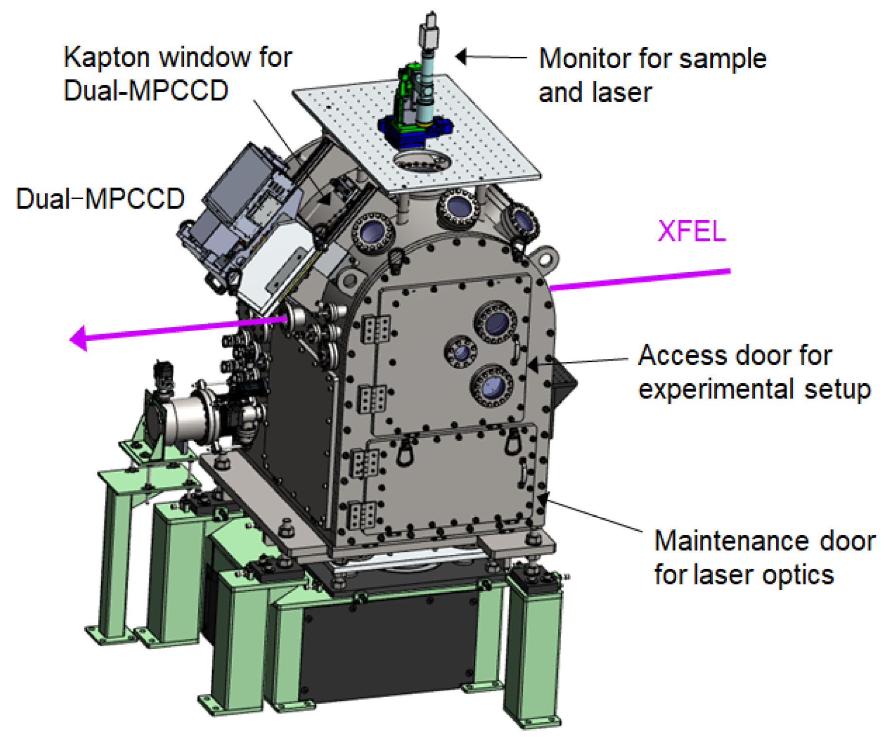
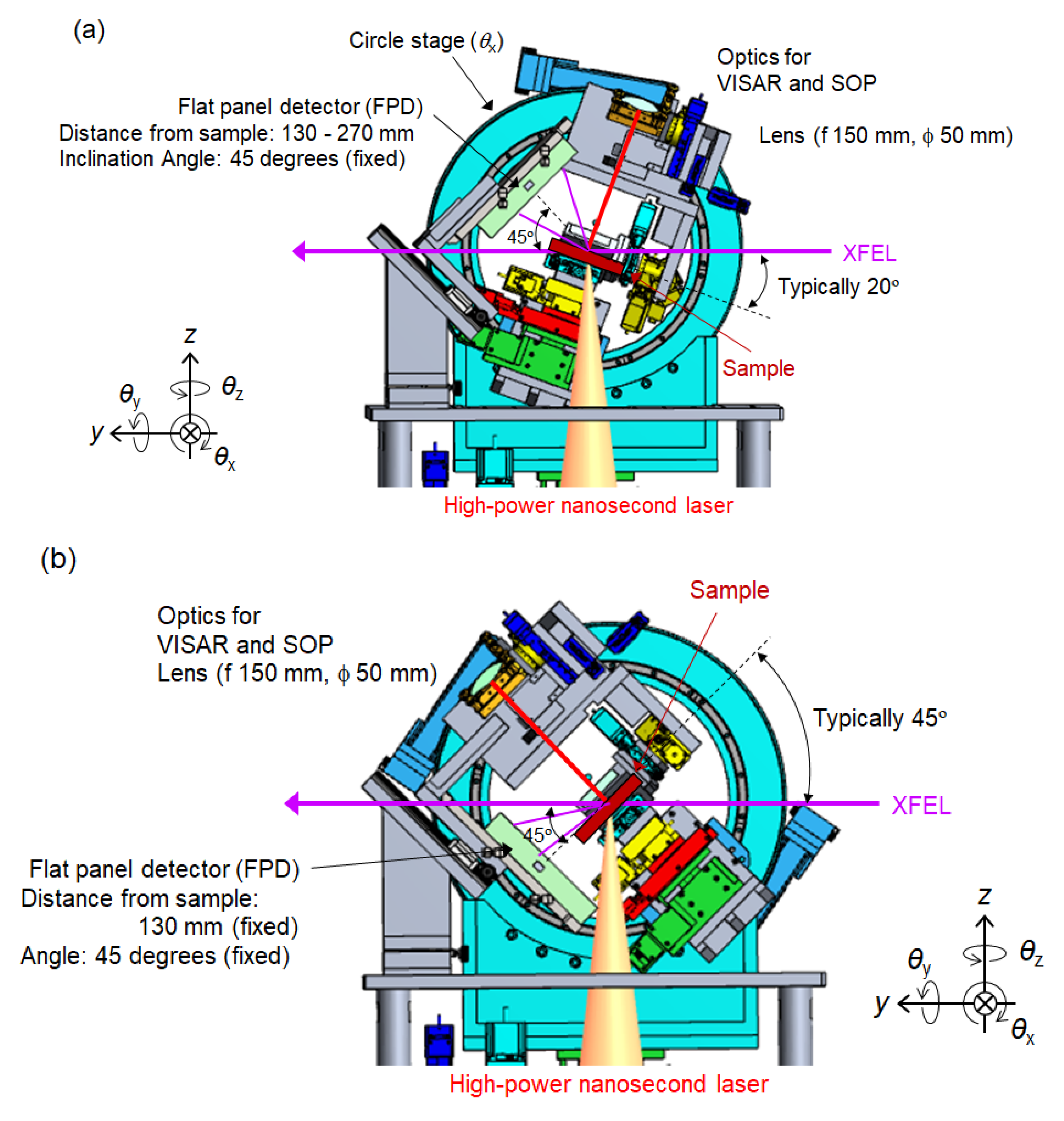
The high-power nanosecond laser, which utilizes power amplifiers using large-aperture Nd:YAG ceramic disks, was manufactured by HAMAMATSU Photonics K.K under the support of Osaka University. The temporal profile of the laser pulse is controllable. The typical pulse has a duration from 3 ns to 10 ns with a quasi-flat-top profile where a rise-and-fall time is less than 1 ns. The maximum pulse energy depends on the temporal profile. For the duration of 10 ns, the maximum pulse energy is around 60 J with the central wavelength of 532 nm, which is the second harmonic of the fundamental wavelength of 1064 nm. The maximum repetition rate is 0.1 Hz, while a shot rate would be limited by shot-by-shot sample delivery. The laser beam is delivered from a laser booth to the experimental chamber through a beam path. Schematics of the experimental chamber is shown in Figure 2. The chamber is typically evacuated to lower than 0.1 Pa during high-power laser shots. The laser beam is introduced to the chamber from the bottom. The angle between the laser and the XFEL is fixed to be 90 degrees. The laser is focused with a lens of which focal length is 500 mm. The focal spot size can be varied depending on the experimental requirement and is typically larger than 100 µm in a diameter. The laser focusing lens, the sample positioning system and some diagnostics are located in the chamber. As an option, a phase plate can be installed for shaping a spatial intensity distribution of the focused laser beam into a flat top pattern. A delay time between a laser pulse and an XFEL pulse can be varied up to the order of a millisecond. The timing jitter is negligible for most experiments since the jitter is sufficiently smaller than the rise time of a laser pulse.
A new sample should be provided shot-by-shot in high-energy nanosecond laser experiments since a sample is generally destroyed by a single laser shot. Several tens of samples can be set on a sample holder, which is aligned by motorized stages with 6 axes (3 translations and 3 rotations). For the alignment procedures, long focus microscopes are equipped to monitor samples from the top and the side.

4. Diagnostics

X-ray diffraction (XRD) measurement is widely used in high-pressure sciences to observe structural changes of a compressed matter. In our experimental platform, instruments for XRD measurement were developed as the main diagnostic. In order to avoid a decrease in signal intensity caused by a polarization factor of the horizontally polarized XFEL pulses, instruments are arranged in the vertical dispersion plane. There are two options in geometries of XRD measurements: a reflection geometry and a transmission geometry. Figure 3a shows the arrangement of the instruments in the reflection geometry. The XRD signal are detected with a flat panel detector (FPD), which is a two-dimensional X-ray image detector. The specification of the FPD is summarized in Table 1. The typical distance from a sample to the FPD detector is 130 mm. In this case, the detectable diffraction angle is from 20 to 80 degrees, so that the range of observation angle is 60 degrees. The angular resolution of a single pixel at the center of the FPD is geometrically estimated to be ~0.04 degrees. The transmission geometry is shown in Figure 3b. In this geometry, the FPD detects diffracted X-rays after passing through a sample. The typical distance from a sample to the FPD is 130 mm, which is the same as the reflection geometry. Thus, the observation range and the angular resolution are also identical. As an optional X-ray detector, a dual multiport charged coupled device (Dual-MPCCD) detector [23]—of which specification is also shown in Table 1—is available. The Dual-MPCCD detector is mounted outside the chamber and can observe the diffracted X-rays through a Kapton window. An angular resolution is much higher than that of FPD due to the small pixels and a long distance from a sample, although the observation range is limited. As complementary techniques, small-angle X-ray scattering measurement (SAXS) and X-ray imaging with absorption or phase contrasts are applicable in this platform.
Instruments for optical measurements were also prepared. A typical optical diagnostic is a Velocity Interferometer System for Any Reflector (VISAR) [24,25] to diagnoses a velocity of a shock wave from a fringe pattern using a probe laser (VISAR laser) reflected by a sample. The final optics of the VISAR system should be mounted on a direction normal to the sample surface for keeping the same axis to both the incident and the reflected paths of the VISAR laser. In the developed chamber, the sample stages and the VISAR final optics are both mounted on the motorized stages on a circle. Therefore, the angle between the sample surface and the VISAR optics can be maintained by adjusting the positions of the stages independently on the circle even when the sample is rotated in θx. Here, it should be noted that all optics for the VISAR in the chamber are also mounted on the circle. Particularly, a mirror placed at the center of the circle to change the beam direction to/from the sample but maintains the direction to/from the window on the chamber wall. This configuration allows keeping the optical path of the VISAR laser independently on the final optics position. A dove prism is used to compensate for the image rotation on the cameras due to the angle adjustment.

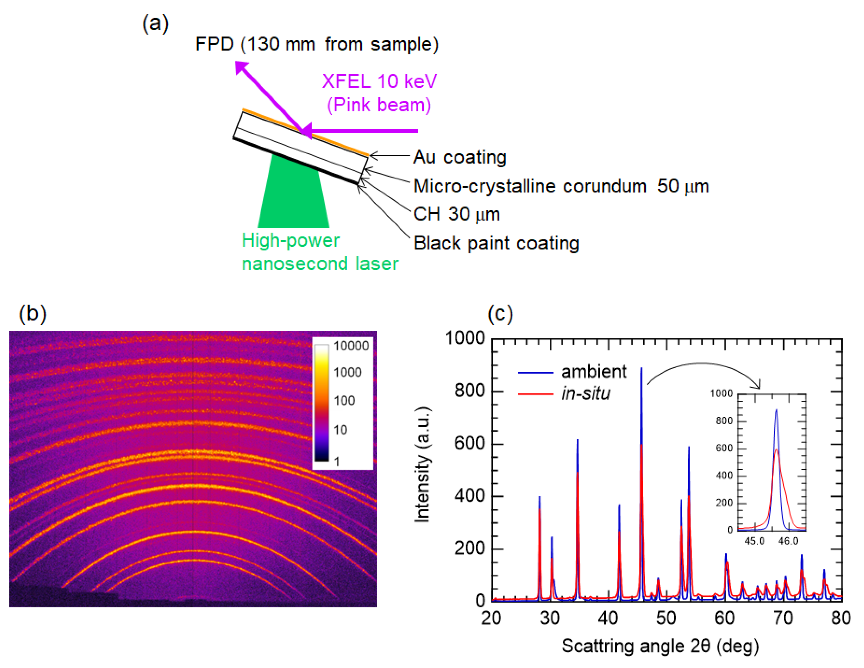
5. Demonstration of Pump-Probe Experiment

We performed X-ray diffraction measurements of a matter under shock-compression in the reflection geometry. The experimental setup is shown in Figure 4a. A multi-layered sample was irradiated by a high-power laser pulse with a pulse energy of 30 J in a 10-ns duration. The time delay between the laser and the XFEL pulses was 11 ns. The XFEL pulse was line-focused to be 30 µm (vertical) in FWHM by using one elliptical mirror of the KB optics. As shown in Figure 4b, owing to the wide observation range of the FPD, multiple diffraction lines from the corundum (Al2O3) were observed in a single-shot measurement. Figure 4c shows line profiles of the diffraction pattern of ambient and in-situ. The most intense peak at 45.5 degrees is the diffraction line of the Al2O3(116). The peak broadening to the large angle side is observed in the in-situ data that is consistent with the compression of the corundum due to the laser irradiation.

6. Summary

We developed a new experimental platform where one can use both an XFEL and a high-power nanosecond laser. The platform is optimized for the experiments to probe the laser-shocked matter with XFELs via XRD and SAXS. The platform has additional capabilities of experimental setups, for example, XFEL nano-focusing and optical diagnostics like VISAR. As a demonstration of pump-probe experiments, we observed the laser-compressed corundum with the single-shot XRD measurement. The experimental platform significantly extends research capabilities in high-pressure science with a novel probe technique.

Author Contributions

Y.I., T.Y., T.T. and M.Y. designed the experimental platform. T.T., K.S., N.O., T.M. and R.K. prepared the high-power laser system and optics. T.O., S.M., K.Y., H.Y., T.K. and H.O. developed the XFEL focusing optics. Y.I., T.Y., T.T., K.S., K.M., Y.T. and K.T. performed the pump-probe experiment and analyzed the data. Y.I. and M.Y. wrote the paper. All authors have read and agreed to the published version of the manuscript.

Funding

This work was supported in part by the X-ray Free Electron Laser Priority Strategy Program at Osaka University from the Ministry of Education, Culture, Sports, Science and Technology (contract 12005014).

Acknowledgments

We would like to acknowledge the supporting members of SACLA. We also thank the reviewers who participated in the design review of the experimental platform.

Conflicts of Interest

The authors declare no conflict of interest.

References

  1. Emma, P.; Akre, R.; Arthur, J.; Bionta, R.; Bostedt, C.; Bożek, J.; Brachmann, A.; Bucksbaum, P.; Coffee, R.; Decker, F.-J.; et al. First lasing and operation of an ångstrom-wavelength free-electron laser. Nat. Photon 2010, 4, 641–647. [Google Scholar] [CrossRef]
  2. Ishikawa, T.; Aoyagi, H.; Asaka, T.; Asano, Y.; Azumi, N.; Bizen, T.; Ego, H.; Fukami, K.; Fukui, T.; Furukawa, Y.; et al. A compact X-ray free-electron laser emitting in the sub-ångström region. Nat. Photon 2012, 6, 540–544. [Google Scholar] [CrossRef]
  3. Kang, H.S.; Min, C.-K.; Heo, H.; Kim, C.; Yang, H.; Kim, G.; Nam, I.; Baek, S.Y.; Choi, H.-J.; Mun, G.; et al. Hard X-ray free-electron laser with femtosecond-scale timing jitter. Nat. Photon 2017, 11, 708–713. [Google Scholar] [CrossRef]
  4. Tschentscher, T.; Bressler, C.; Grünert, J.; Madsen, A.; Mancuso, A.P.; Meyer, M.; Scherz, A.; Sinn, H.; Zastrau, U. Photon Beam Transport and Scientific Instruments at the European XFEL. Appl. Sci. 2017, 7, 592. [Google Scholar] [CrossRef] [Green Version]
  5. Milne, C.; Schietinger, T.; Aiba, M.; Alarcon, A.; Alex, J.; Anghel, A.; Arsov, V.; Beard, C.; Beaud, P.; Bettoni, S.; et al. SwissFEL: The Swiss X-ray Free Electron Laser. Appl. Sci. 2017, 7, 720. [Google Scholar] [CrossRef]
  6. Chapman, H.N.; Fromme, P.; Barty, A.; White, T.A.; Kirian, R.; Aquila, A.; Hunter, M.S.; Schulz, J.; DePonte, D.P.; Weierstall, U.; et al. Femtosecond X-ray protein nanocrystallography. Nature 2011, 470, 73–77. [Google Scholar] [CrossRef] [PubMed]
  7. Suga, M.; Akita, F.; Hirata, K.; Ueno, G.; Murakami, H.; Nakajima, Y.; Shimizu, T.; Yamashita, K.; Yamamoto, M.; Ago, H.; et al. Native structure of photosystem II at 1.95 Å resolution viewed by femtosecond X-ray pulses. Nature 2014, 517, 99–103. [Google Scholar] [CrossRef] [PubMed]
  8. Yoneda, H.; Inubushi, Y.; Nagamine, K.; Michine, Y.; Ohashi, H.; Yumoto, H.; Yamauchi, K.; Mimura, H.; Kitamura, H.; Katayama, T.; et al. Atomic inner-shell laser at 1.5-ångström wavelength pumped by an X-ray free-electron laser. Nature 2015, 524, 446–449. [Google Scholar] [CrossRef] [PubMed]
  9. Bostedt, C.; Boutet, S.; Fritz, D.M.; Huang, Z.; Lee, H.J.; Lemke, H.T.; Robert, A.; Schlotter, W.F.; Turner, J.J.; Williams, G.J. Linac Coherent Light Source: The first five years. Rev. Mod. Phys. 2016, 88, 015007. [Google Scholar] [CrossRef] [Green Version]
  10. Mao, H.K.; Wu, Y.; Chen, L.C.; Shu, J.F.; Jephcoat, A.P. Static compression of iron to 300 GPa and Fe0.8Ni0.2alloy to 260 GPa: Implications for composition of the core. J. Geophys. Res. Space Phys. 1990, 95, 21737–21742. [Google Scholar] [CrossRef]
  11. Mao, H.K.; Chen, X.-J.; Ding, Y.; Li, B.; Wang, L. Solids, liquids, and gases under high pressure. Rev. Mod. Phys. 2018, 90, 015007. [Google Scholar] [CrossRef] [Green Version]
  12. Inubushi, Y.; Tono, K.; Togashi, T.; Sato, T.; Hatsui, T.; Kameshima, T.; Togawa, K.; Hara, T.; Tanaka, T.; Tanaka, H.; et al. Determination of the Pulse Duration of an X-ray Free Electron Laser Using Highly Resolved Single-Shot Spectra. Phys. Rev. Lett. 2012, 109, 144801. [Google Scholar] [CrossRef] [PubMed]
  13. Inubushi, Y.; Inoue, I.; Kim, J.; Nishihara, A.; Matsuyama, S.; Yumoto, H.; Koyama, T.; Tono, K.; Ohashi, H.; Yamauchi, K.; et al. Measurement of the X-ray Spectrum of a Free Electron Laser with a Wide-Range High-Resolution Single-Shot Spectrometer. Appl. Sci. 2017, 7, 584. [Google Scholar] [CrossRef]
  14. Nagler, B.; Arnold, B.; Bouchard, G.; Boyce, R.F.; Boyce, R.M.; Callen, A.; Campell, M.; Curiel, R.; Galtier, E.; Garofoli, J.; et al. The Matter in Extreme Conditions instrument at the Linac Coherent Light Source. J. Synchrotron Radiat. 2015, 22, 520–525. [Google Scholar] [CrossRef] [PubMed]
  15. Nakatsutsumi, M.; Appel, K.; Baehtz, C.; Chen, B.; Cowan, T.; Göde, S.; Konopkova, Z.; Pelka, A.; Priebe, G.; Schmidt, A.; et al. Femtosecond laser-generated high-energy-density states studied by X-ray FELs. Plasma Phys. Control. Fusion 2016, 59, 14028. [Google Scholar] [CrossRef]
  16. Albertazzi, B.; Ozaki, N.; Zhakhovsky, V.V.; Faenov, A.; Habara, H.; Harmand, M.; Hartley, N.J.; Ilnitsky, D.; Inogamov, N.; Inubushi, Y.; et al. Dynamic fracture of tantalum under extreme tensile stress. Sci. Adv. 2017, 3, e1602705. [Google Scholar] [CrossRef] [Green Version]
  17. Tono, K.; Togashi, T.; Inubushi, Y.; Sato, T.; Katayama, T.; Ogawa, K.; Ohashi, H.; Kimura, H.; Takahashi, S.; Takeshita, K.; et al. Beamline, experimental stations and photon beam diagnostics for the hard X-ray free electron laser of SACLA. New J. Phys. 2013, 15, 083035. [Google Scholar] [CrossRef]
  18. Bonifacio, R.; Pellegrini, C.; Narducci, L. Collective instabilities and high-gain regime in a free electron laser. Opt. Commun. 1984, 50, 373–378. [Google Scholar] [CrossRef] [Green Version]
  19. Huang, Z.; Kim, K.-J. Review of X-ray free-electron laser theory. Phys. Rev. Spéc. Top. Accel. Beams 2007, 10, 034801. [Google Scholar] [CrossRef]
  20. Katayama, T.; Owada, S.; Togashi, T.; Ogawa, K.; Karvinen, P.; Vartiainen, I.; Eronen, A.; David, C.; Sato, T.; Nakajima, K.; et al. A beam branching method for timing and spectral characterization of hard X-ray free-electron lasers. Struct. Dyn. 2016, 3, 034301. [Google Scholar] [CrossRef] [Green Version]
  21. Inoue, I.; Osaka, T.; Hara, T.; Tanaka, T.; Inagaki, T.; Fukui, T.; Goto, S.; Inubushi, Y.; Kimura, H.; Kinjo, R.; et al. Generation of narrow-band X-ray free-electron laser via reflection self-seeding. Nat. Photon 2019, 13, 319–322. [Google Scholar] [CrossRef]
  22. Hara, T.; Inubushi, Y.; Katayama, T.; Sato, T.; Tanaka, H.; Tanaka, T.; Togashi, T.; Togawa, K.; Tono, K.; Yabashi, M.; et al. Two-colour hard X-ray free-electron laser with wide tenability. Nat. Commun. 2013, 4, 2919. [Google Scholar] [CrossRef] [PubMed] [Green Version]
  23. Kameshima, T.; Ono, S.; Kudo, T.; Ozaki, K.; Kirihara, Y.; Kobayashi, K.; Inubushi, Y.; Yabashi, M.; Horigome, T.; Holland, A.; et al. Development of an X-ray pixel detector with multi-port charge-coupled device for X-ray free-electron laser experiments. Rev. Sci. Instrum. 2014, 85, 33110. [Google Scholar] [CrossRef] [PubMed]
  24. Barker, L.M.; Hollenbach, R.E. Laser interferometer for measuring high velocities of any reflecting surface. J. Appl. Phys. 1972, 43, 4669. [Google Scholar] [CrossRef]
  25. Celliers, P.M.; Bradley, D.K.; Collins, G.W.; Hicks, D.; Boehly, T.; Armstrong, W.J. Line-imaging velocimeter for shock diagnostics at the OMEGA laser facility. Rev. Sci. Instrum. 2004, 75, 4916–4929. [Google Scholar] [CrossRef] [Green Version]
Figure 1. Intensity profiles of focused X-ray free electron laser (XFEL) pulses in (a) vertical direction and (b) horizontal direction. Focal spot sizes, which are derived from Gaussian fitting of differential of knife-edge scan results, are (a) 480 nm and (b) 430 nm, respectively.
Applsci 10 02224 g001
Figure 2. Schematic of the experimental chamber. In the chamber, high-power nanosecond laser, which is focused by a lens with a focal length of 500 mm, irradiates a sample from the bottom side. The laser focusing lens, sample system and a flat panel detector are placed in the chamber. A dual multiport charged coupled device (Dual-MPCCD) detector locates outside the chamber.
Applsci 10 02224 g002
Figure 3. Experimental configurations of X-ray diffraction (XRD) measurements for (a) reflection geometry and (b) transmission geometry in the experimental chamber. To avoid a decrease of the XRD signal caused by a polarization factor, the dispersion plane of XRD measurement is vertical. Optics for VISAR can keep the normal direction of a sample surface, even when an angle of a sample is changed.
Applsci 10 02224 g003
Figure 4. (a) Schematic of experimental setup in the reflection geometry. (b) In-situ single-shot diffraction pattern detected with the flat panel detector (FPD). (c) Line profiles of diffraction pattern of ambient and in-situ.
Applsci 10 02224 g004
Table 1. Detectors for XRD measurements.
Flat Panel Detector (FPD)Dual MultiPort Charged Coupled Device (Dual-MPCCD)
Active area204 × 153 mm251 × 51 mm2
Pixel size99 m50 m
Number of pixels2064 × 15481024 × 1024
PlaceInside chamber (in vacuum)Outside chamber (in air)
Typical distance from sample130 mm640 mm
Observation range at typical distance60 degrees4.6 degrees
Angular resolution of a pixel on detector center at typical distance0.04 degrees0.004 degrees

