1. Introduction
Welding, particularly of parts made of high-strength low-alloyed steels, is a very complex process. There are numerous parameters that make the welding process complicated. The high-strength low-alloyed steel (HSLA) producers usually prescribe the relevant welding parameters to be applied in welding of these steels. They are considered as conditionally weldable, which means that certain special measures must be applied that would provide for the successful execution of the welded joints. It is also a known fact that welding, due to changes in their microstructure, causes degradation of otherwise exceptional mechanical properties of those steels. The changes are especially prominent in the heat-affected zone (HAZ) of the welded joints. They cause increase of stiffness and brittle to ductile transition temperature, while simultaneously causing decrease of toughness. In addition, due to the fast cooling of the butt weld, it is possible for brittle phases to appear, as well as cracks within the welded metal, since the cooling is done within the temperature limits characterized by the largest instability of austenite. Due to all of these factors, it is necessary to consider all the aspects of the applied welding technology, with all the possible negative effects that it can cause.
The impact toughness of a welded joint is defined as its ability to permanently deform while absorbing the energy before fracturing, i.e., it is the amount of energy the welded joint can take before cracking. The general objective is thus to increase the impact toughness of the welded joints, whichis influenced by several factors, namely the welding procedure parameters. The first is the filler metal, i.e., the properly chosen filler metal can provide for good impact toughness of the welded joint and minimize the extent and rate of cracking. Using such a filler metal, with an appropriately selected welding procedure, can prevent cracking of the welded structure altogether. Besides the adequate filler metal and the welding procedure, aninfluencing parameter is the shielding gas. The rule for obtaining satisfactory impact toughness of the welded joint is to use the shielding gas recommended by the manufacturer for the particular combination of the base and filler metal. The heat treatments are also very important factors. The preheating of the base metal, as well as maintaining the proper interpass temperatures during the welding, are of the utmost importance. The slow cooling rate of the welded joint can minimize the problems of inadequate microstructure of its different zones, which can negatively affect the impact toughness of the whole structure. The post-welding heat treatment is aimed at relieving the residual stresses that appeared during the welding. In this paper, the emphasis is on the influence of the welding procedure on impact toughness of the welded joint of the high-strength low-alloyed steel, i.e., the comparison was performed of the two combinations of the welding procedures for executing the single V butt multi-pass welded joints of such steels.
Problems related to welding of steels were subjects of research of numerous authors. Here presented is only a brief survey of some of those research results, mainly related to the study of the impact toughnessof HSLA steel welded joints.
Authors in [
1] analyzed the influence of morphology of martensite–austenite constituents on impact toughness of HSLA steel welds in the inter-critically reheated coarse-grained heat-affected zones and concluded that slender constituents are more destructive to joint toughness than massive ones. Application of super-martensitic stainless steels (SMSS), characterized by good weldability, for fabrication of onshore and offshore pipelines, was considered in [
2]. The welded areas of the SMSS pipes can be exposed to stress corrosion cracking. Apost-weld heat treatment was proposed consisting of holding the welded joint for 5 min at about 650 °C, to eliminate that risk. An experimental research of welding effects on tensile characteristics of the T-welds of the high-strength low-alloyed steel was presented in [
3]. Experimentally obtained values of mechanical characteristics in the elastic zone were higher than the related values calculated according to Eurocode 3 standard: Design of steel structures [
4]. The authors concluded that the standard conservatively prescribes determination of the HSLA steel weld characteristics.
Authors of [
5] presented an experimental investigation of the influence of welding on strength of high performance steels. They concluded that welding significantly softened the heat affected zone in HSLA steel, with insignificant effects on the normal strength. The gas metal welding (GMA) of the HY-80 steels, with application of different welding parameters, was investigated in [
6]. The executed test welds had values of the Charpy impact toughness similar to values in the weld metal and the HAZ; the measured values of hardness in the weld metal and the base metal were almost similar, while in the HAZ the values were higher. Authors in [
7] presented an analysis of microstructural characteristics and mechanical properties of dissimilar joining welds of API 5L X60 ferritic HSLA steel and AISI 310S austenitic stainless steel (SŽ “Fiprom”, Jesenice, Slovenia). Experimentally obtained values led to the conclusion that for dissimilar welding between those two steels, the weld metal done by the ER2209 (SŽ “Fiprom”, Jesenice, Slovenia) duplex stainless steel filler metal provided the best mechanical properties.
The multi-run welding of HSLA steel plates, executed by the manual metal arc (MMA) procedure, was investigated in [
8]. Authors reported that it was relatively easy to fulfill requirements for the good mechanical strength of the weld metal, but that it was much more difficult to obtain good toughness and fatigue strength in the multi-run weld metal. Research of the influence of the welding parameters on the HSLA steel and on hardness and impact energy of samples, welded at related welding parameters, was presented in [
9]. It was found that it was necessary to control and apply the optimal welding parameters, since even the slightest deviation from any of them could cause significant degradation in the quality of the welded joint. Authors in [
10] presented a comparative study of the tensile and impact properties of the multi-pass SMAW Armox 500T steel joints (SSAB, Oxelosund, Sweden). The welds were executed with application of two different consumables: austenitic stainless steel and low hydrogen ferritic steel. The austenitic stainless steel consumable can be considered as a candidate welding consumable that can provide for good strain hardening and toughness of the welded joint, but the low hydrogen ferritic consumable is recommended for welded joints that require higher joint efficiency under tensile loading conditions. Research of the multi-pass welded joints of high-strength low-alloyed steel, done by underwater local cavity welding and underwater dry welding techniques, was reported in [
11]. The authors obtained lower values of the yield strength and ultimate tensile strength on underwater local cavity welded specimens than on the underwater dry welding joint specimens. Still, the impact toughness was much higher for specimens of the latter technique.
Authors of [
12] implied that an important step in the design and fabrication of welded structures is selection of the welding process and the filler consumables. They applied three different welding techniques. Their experimental results showed that the higher level of residual stresses was registered in modified short arc welding and in flux cored arc welding than in shielded metal arc welding. They assumed that the higher levels of residual stresses were probably related to formation of bainite and Widmanstätten ferrite in the weld metal and HAZ. Mechanical characteristics of the HAZ of the HSLA steel weld were dominant to both, resulting in mechanical characteristics and mechanical behavior of the welds during exploitation [
13,
14,
15]. Mechanical characteristics, in correlation with evaluation of microstructures in specific zones of welds, as well as analysis of the microhardness distribution, are the basis for design of welded structuresmade of HSLA steels. The full advantages provided by the related material usage can be achieved only by this design perspective [
14,
15]. Influence of the HAZ characteristics on overall characteristics of the welds of low-carbon steels is analyzed in [
16]. That zone is characterized by altered microstructures and high levels of residual stresses. The authors concluded that rough grains of microstructure appearedwithintensive heat input in the HAZ, whichthen caused lower values of hardness.
Authors in [
17] studied the influence of the welding technology, byexecuting a “single V” butt multiple-pass welded joint, on impact toughness of welded joints of high-strength low-alloyed steels. It should be noted that a much more detailed literature review on problems related to welding of the HSLA steels is presented in that article. Based on that review, the authors concluded that the contemporary referent literature sources discuss the impact only of certain parameters on the microstructure and in certain zones of the weld and that it is necessary to establish the correlation between the microstructure parameters and mechanical characteristics of the welded joints. Authors of [
18] were considering using different cutting techniques for HSLA steels. They presented results of the impact of the cutting technology on changes of hardness in the cutting zone of Hardox 400 and 450 steels.
Influence of the welded joints’ quality on safety and reliability in operation was studied in [
19]. The poorly executed welded joint of steels can be causes of fracture and even crashes of plants. Authors observed various defects, like pores, blowholes, slags, lack of fusion, non-plastic non-metallic particles, cracks and shrink holes in the welded joint area, which resulted in fracture of rails and pipes made of HSLA steels. A trend in the automotive industry for reducing the mass of cars and semi-trailers was considered in [
20], where an important factor is guaranteed safety of use and safe operation life of such vehicles. The authors presented results of fatigue tests in the range of low and high cycle fatigue of wear resistant quenched and tempered martensitic Hardox steel 400 and 450 steels and discussed the influence of the grain size on the shape of fatigue curves and compared those results to fatigue tests of S355J2 structural steel results.
In [
21] are presented selected experimental results of investigation of the fatigue resistance of structural steels. The authors performed experiments on nine structural steels including high strength steels, DOMEX 700MC, HARDOX 400, HARDOX 450 and 100Cr6 (SSAB, Oxelosund, Sweden) (UTS from 446 MPa to 2462 MPa) at high-frequency cyclic loading (f = 20 kHz, T = 20 ± 5 °C, R = −1) in the range of the loading cycle numbers from 2 × 10
6 to 2 × 10
9. The continuous decrease of fatigue strength in terms of the increasing number of loading cycles was observed.
Since the cooling rate is variable and decreases with the temperature decrease, the cooling time from 800 to 500 °C (t
8/5) is usually taken as the parameter that best characterizes the cooling conditions of the HAZ, with respect to the lowest stability of austenite of the majority of steels. The cooling time, in that temperature range, can be calculated according to different expressions, as well as determined experimentally. Knowing that cooling time and relevant material properties enables prediction of characteristics of the welded joint and the heat affected zone [
22,
23,
24].
Compared to conclusions of the presented references, this paper presents an analysis of the welding effects on impact toughness of high-strength low-alloyed steels for the two combinations of the most commonly used welding procedures in industry at present. The research further establishes the basic qualitative relations between the pre-existing microstructure, relevant microhardness values and measured values of the impact toughness.
2. Experimental Procedure
Tests were performed on samples made of high-strength low-alloyed steel of class S690 (standard EN 10025-6:2004 [
25]). The chemical composition of the considered steel is given in
Table 1. Experimental welds were executed by multiple-pass V-groove butt weld joints at the central zones. The root passes of considered welds were executed in two different ways: by the manual metal arc (MMA) procedure, and by the metal inert gas (MIG) procedure in the protective atmosphere of 100% Ar. The filling and covering passes were executed by the metal active gas (MAG) welding procedure in the gas compound (82% Ar + 18% CO
2). Before welding, it was necessary to prepare the groove. Shape and dimensions of the welding grooves for both considered welding procedures are presented in
Figure 1. The applied welding parameters and related consumables of the welding procedures are presented in
Table 2.
The preheating temperature was prescribed by the steel manufacturer (100 °C). The time between the interpasses was measured and until the temperature of the deposited layer did not drop below 225 °C, and it amounted to between 3 and 5 min.
Metallographic analysis of the welds, which included measuring microhardness, was done in three parallel directions in the cross-sections of prepared metallographic samples. The cross-sections of metallographic samples, with marked measurement directions and microhardness measuring spots, for both considered welding procedures, are presented in
Figure 2. The basic chemical and mechanical characteristics of used consumables are presented in
Table 3.
The used filler metals marks by EN codes and usual applications are as follows:
INOX B 18/8/6 (mark E 18 8 Mn B 22 according to EN 1600)—Applied as interlayers for application of the root welds aimed to decrease the residual stresses and increase the weld plasticity and toughness;
MIG 75 (mark Mn3Ni1CrMo according to EN 12534)—For fine grains high-strength low-alloyed steel welding with yield stress up to 690 MPa;
MIG 18/8/6 Si (mark G 18 8 Mn according to EN 12072)—Applied for welding of the austenite and manganese steels of difficult weldability. It enables absorption of the high residual stresses due to the welding that is very important for high stiffness of a welded structure.
Directions of analysis and microhardness measuring spots were set in characteristic zones in metallographic sample cross-sections so that they ran through the parent metal, heat-affected zone and the weld metal:
I–I was on the face of the weld;
II–II was in the central zone with interfered impacts of the root and other passes and
III–III was on the side of the root pass. Microhardness testing was performed according to the standard SRPS EN ISO 9015-1: 2013, [
26]. Microhardness was measured on a Vickers HPO 250 (Aquastyl, Považská Bystrica, Slovakia) with diamond pyramid load F = 98.1
N (HV 10). The hardness of the standard (etalon) was 473
HV, and it was used to calibrate the device. A microhardness tester type HPO-250KR/AQ (Aquastyl, Považská Bystrica, Slovakia) was used. The microstructure state was evaluated by the reflex optic micrograph method at magnifications of 200 and 500×.
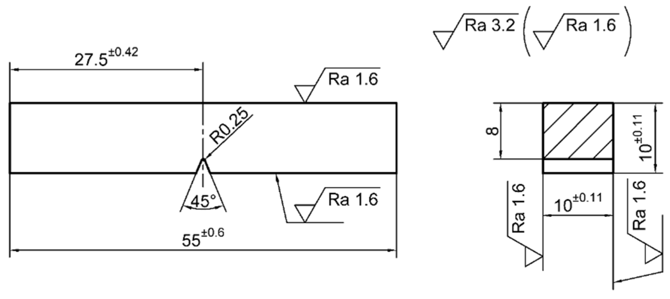
The next phase of experimental tests, which was conducted to evaluate the impact toughness of the executed welded joints and to analyze the mechanical behavior during the fracture, was done on aseries of three test samples, each with welded joints obtained by the MMA/MAG and MIG/MAG procedures. Specimens were notched at the characteristic zones from the face side and then on the root side of the welded joint. Shapes and dimensions of the test samples for the impact toughness testing of type ISO-
V (55 × 10 × 10) are presented in
Figure 3. The testing procedure, shape and dimensions of the test samples were in compliance with adequate standards [
27]. The pendulum speed for the impact toughness test was 5.1 m/s (machine range was 5 to 5.5 m/s; calibrated for measurements errors of 1%), while the energy loss was less than 1%. Experimental testing was carried out at room temperature.
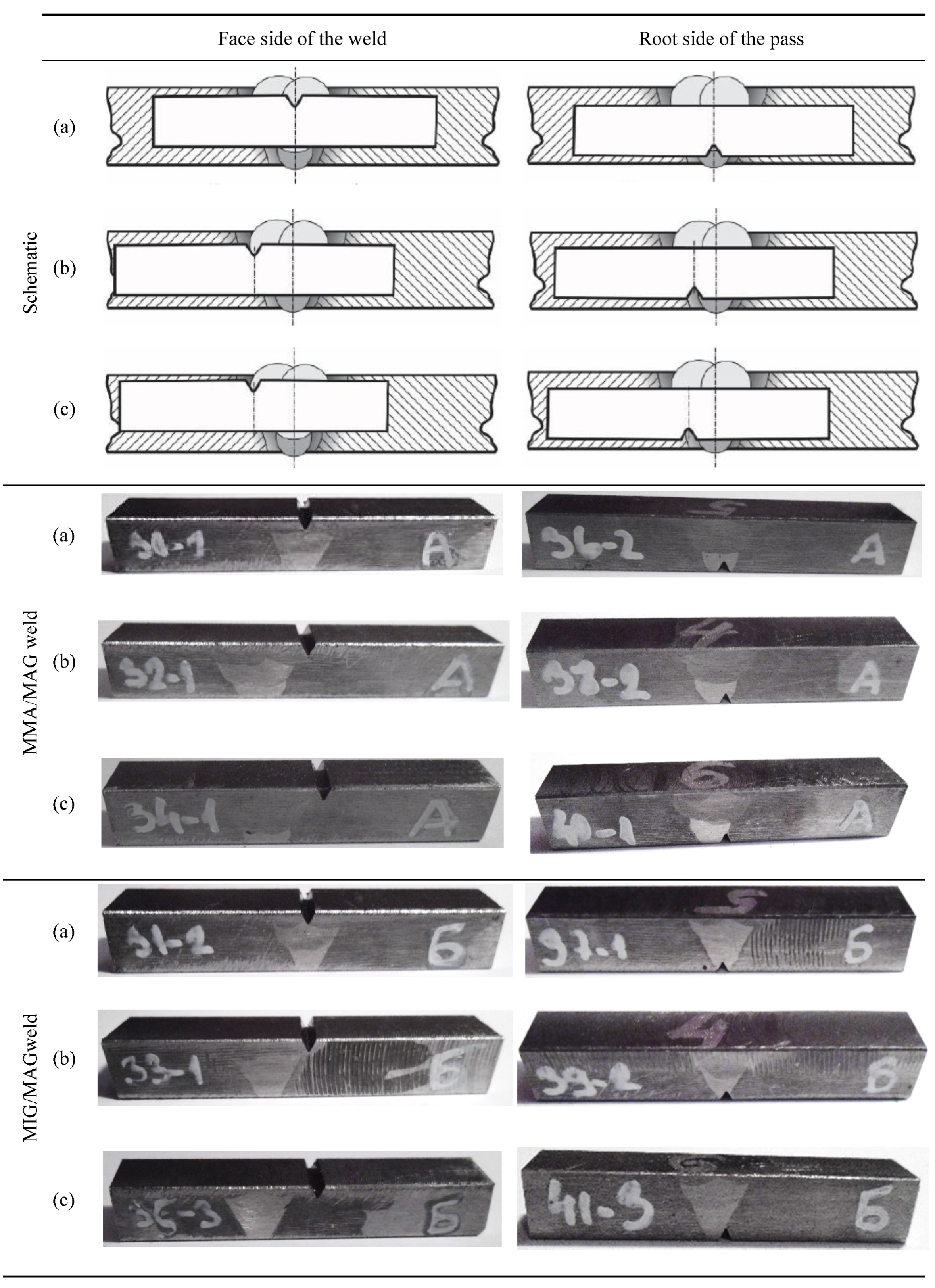
The tests were then done on samples that contained welded joints, executed by both welding procedures, with notches that were positioned along the weld axis, in the zone of fusion, and in the HAZ, both on the face and on the root pass side. The characteristic zones of the weld became visible by chemical etching with a 4% initial solution, which enabled precise positioning of the notch. The notch positions on test samples with the welded joint are presented in
Figure 4.
3. Discussion of Results
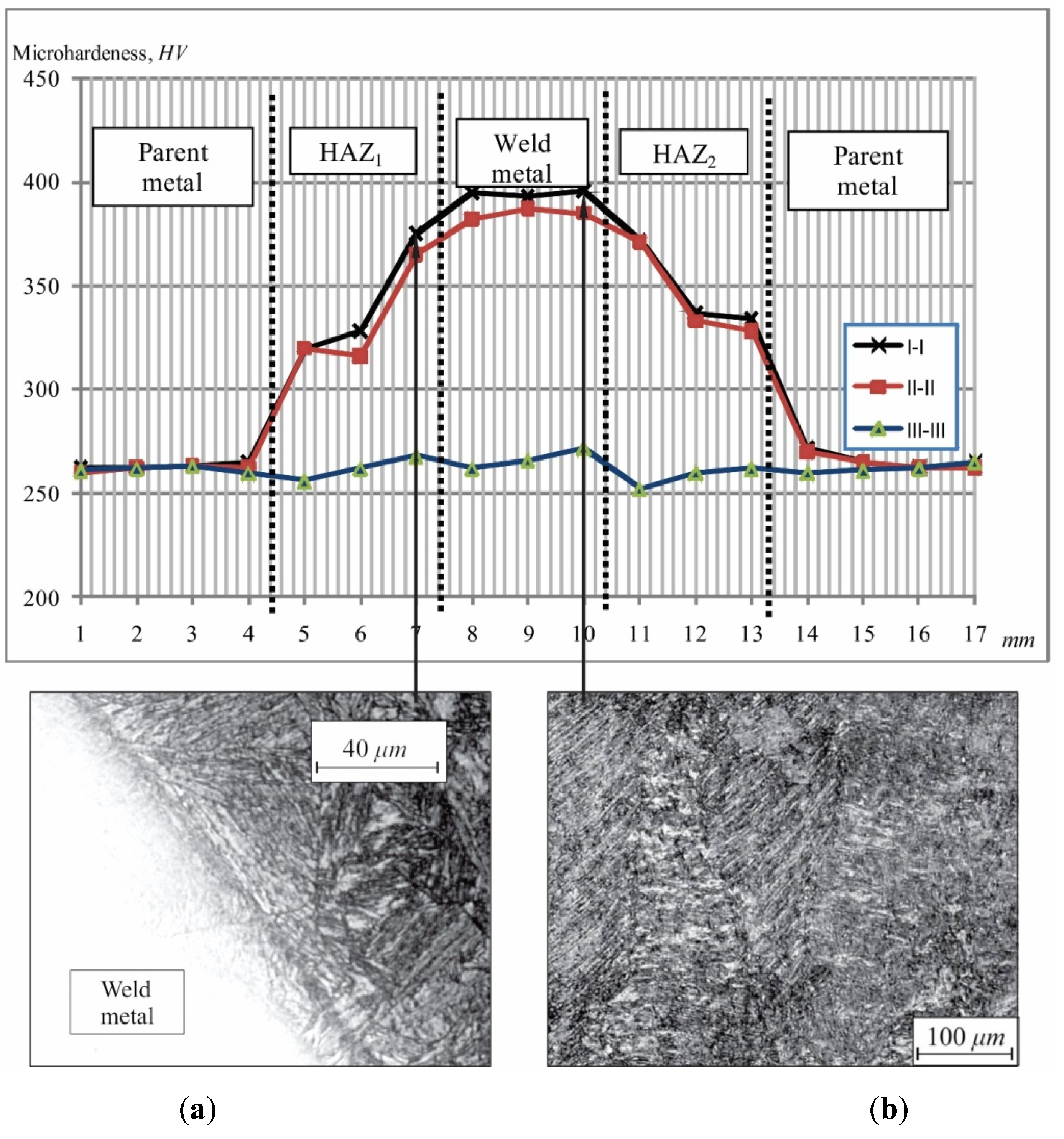
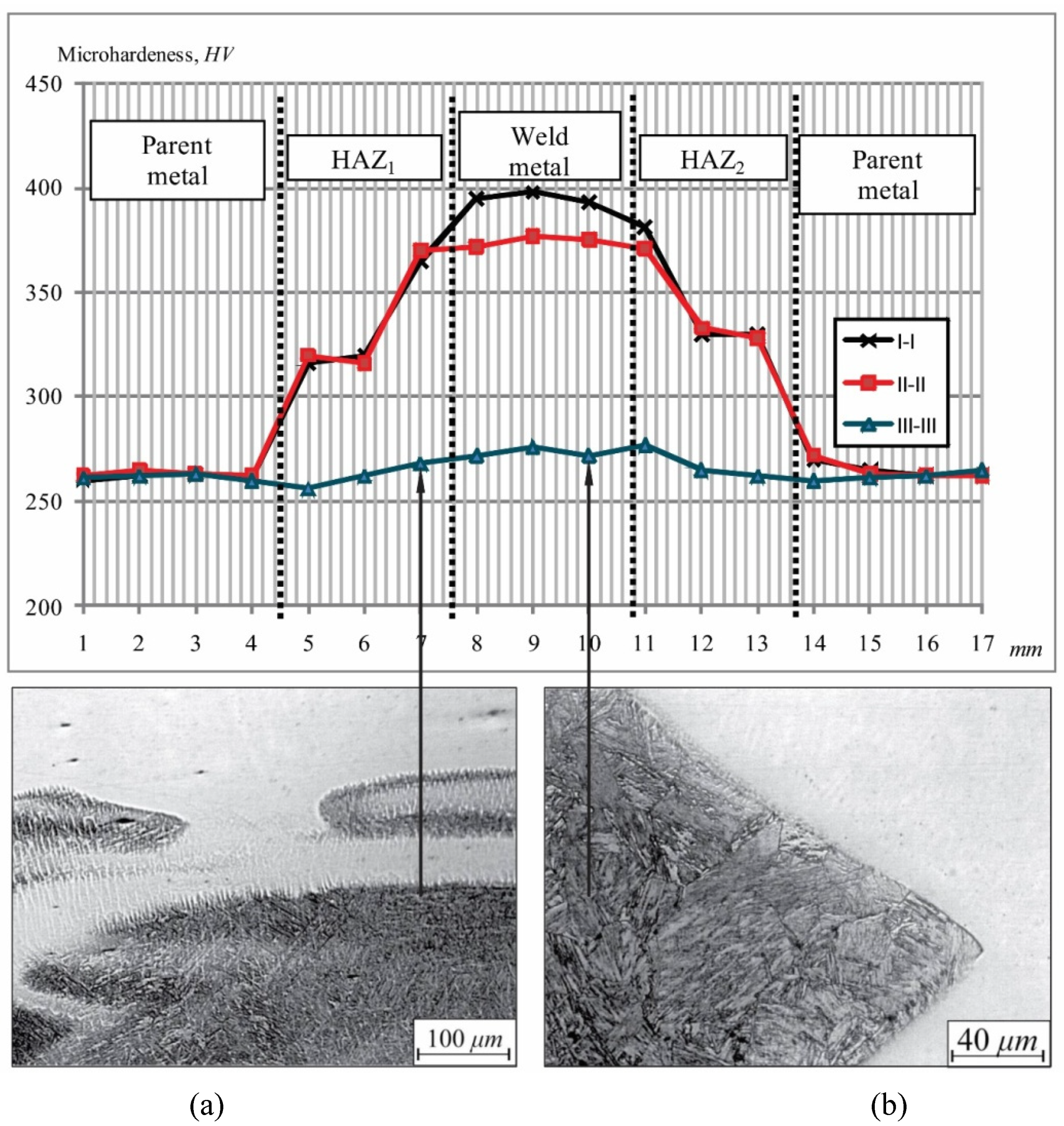
The microhardness distribution along all the three considered directions, as well as micro-photography of the pre-existing microstructure states, for welds obtained by both procedures are shown in
Figure 5 and
Figure 6.
According to diagram of the microhardness distribution in all directions, for the MMA/MAG procedure sample (
Figure 5), it is evident that the microhardness measured values did not exceed the critical values of the brittle structure formation, which is in accordance with the fact that no brittle structures of microstructural states were recorded in the micrographic analysis. The fine-grain and coarse grain zones were present in the HAZ along all the directions and are common for a large number of welding procedures by melting. In direction
I–I the coarse grain bainite microstructure with quenched martensite was registered at the spots close to the fusion zone. In the HAZ, close to the parent metal, a favorable fine-grain ferrite–pearlite structure with bainite was registered. The slightly higher microhardness was registered in the weld metal as compared to the microhardness measured in the HAZ, while the microstructure was assessed as the coarse grain bainite with a higher share of martensite, which correlated with measured microhardness values (
Figure 5b). The measured microhardness values in direction
II–II were lower than those in specific zones in direction
I–I and didnot exceed the critical values relevant for the brittle microstructural states. The lower microhardness values resulted from the microstructure relief due to the heat input from the filling passes of the multiple-pass welding. The coarse grain microstructure of the HAZ in direction
III–III of metallographic samples was bainite without bold acicular structures. The root pass metal weld remained non-erosive during the preparation of metallographic samples due to the high-alloyed filler material used for the root pass, as presented in
Figure 5a. The transient zone between the weld metal and the HAZ was characterized as bainite microstructure without acicular tendency, in compliance with the lowest microhardness measured in this zone, as compared to the related values in direction
II–II [
17].
Values of the cooling time t
8/5 were obtained within a range of 5.2 to 12.1
s. Different theoretical formulas predict values that could range from 4
s (Ito–Bessyo formula) to 65
s (formula of limited thickness) [
24], so the experimentally obtained values were in compliance with theoretically predicted ones.
Observed microstructures for the MIG/MAG procedure sample (
Figure 6) in direction
I–I were similar to the corresponding microstructures of the metallographic sample with the MMA/MAG weld. That implies the dominant impact of the filling passes were the same for both group of samples, namely the MIG/MAG and MMA/MAG welds. The microstructure in the fine-grain HAZ along direction
I–I, as in the case of the MMA/MAG welded joint, was fine-grain pearlite with a possibly smaller share of bainite. In the coarse grain HAZ, the dominant was coarsened grain bainite microstructure with a possible share of a quenched martensite. The microstructural state in the coarsened grain HAZ along direction
III–III for the MIG/MAG procedure was assessed as bainite microstructure without expressed acicular orientation (
Figure 6a,b).
The position of the fusion zone of the weld metal of the root and filling passes pointed to the largerheight of the root pass in the MIG/MAG weld than in the MMA/MAG one, whichwas adequate for the geometry of the welding grooves and common practices.
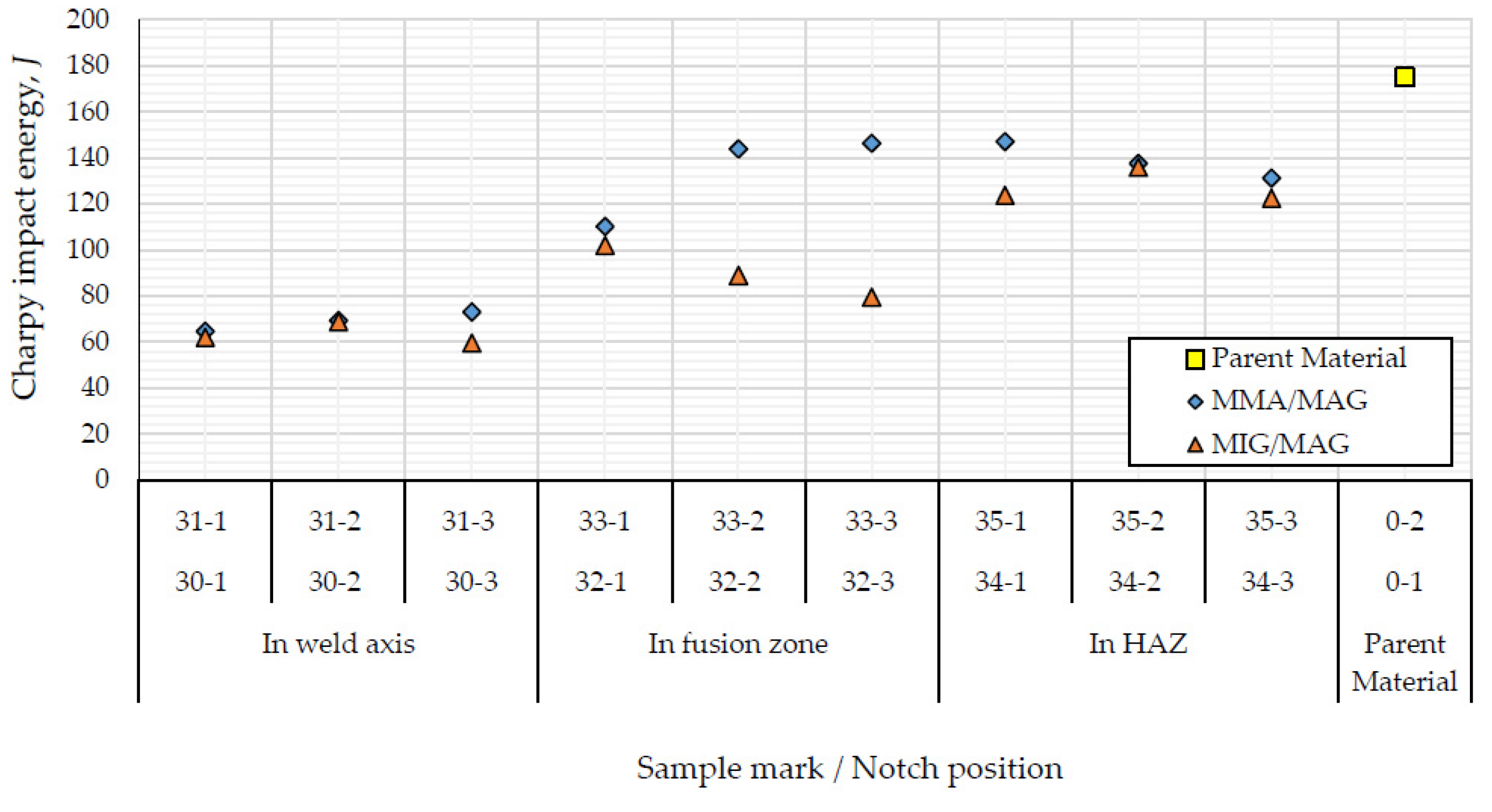
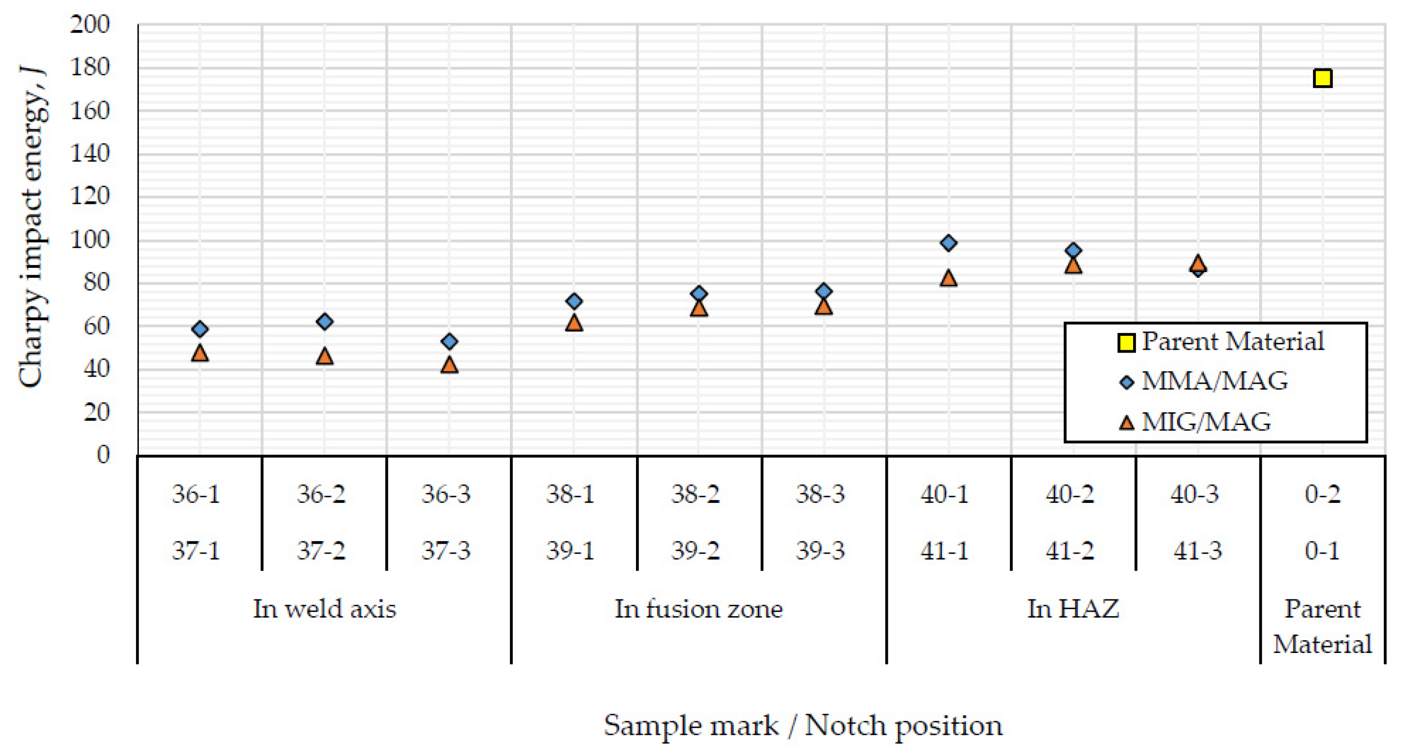
For the purpose of assessment of the applied technology of welding influence on impact toughness and mechanical reaction during the fracture, the comparison was made of related fracture energy values obtained from the test samples that contain discussed MMA/MAG and MIG/MAG welds with notches on the face and root sides, positioned in different zones of the weld. Experimentally obtained values of the fracture energy of the test samples with a notch on the face side of considered welds are presented in
Figure 7, while for the test samples with a notch on the root side, they are shown in
Figure 8.
The comparative analysis of experimentally obtained fractureenergyvalues (forthe impact toughness testing) of samples with a notch on the face side of the MMA/MAG and MIG/MAG welds can be done based on diagrams presented in
Figure 7. Experimentally obtained fracture energy of the test samples with a notch along the axis at the face side of the weld, made by the MMA/MAG and MIG/MAG procedures, were approximately the same, whichimplies that the welding procedure didnot impact the fracture energy of this type of sample. Due to the fact that the filling passes of both considered welds were done in the completely same way, it can be concluded that the filling passes had a dominant impact on the fracture energy values of the samples with a notch along the axis on the face side of the welded joint. Based on the diagram, presented in
Figure 7, it can be concluded that the fracture energy for samples with a notch in the fusion zone was higher for the MMA/MAG welding procedures, which can be related to obtaining better penetration of the fusion zone and geometry of the weld groove. If the fracture energy is taken as a criterion for samples with a notch in the HAZ, the advantage is on the side of the MMA/MAG welding procedure.
The fracture energy of test samples with a notch on the face side in specific zones of the MMA/MAG and MIG/MAG welds were approximately the same with insignificant discrepancies. The fracture energy that was experimentally measured on samples with a notch on the face side in the fusion zone of the MMA/MAG weld were higher than values corresponding to the MIG/MAG welding. Such a distribution of energy along different zones on the face side of the welds indicated that from this aspect, the MMA/MAG procedure provided favorable mechanical characteristics. Due to the fact that the two considered welding procedures (MMA/MAG and MIG/MAG) differed by technology applied for the root pass, it can be concluded that those technologies had minimal influence on the fracture energy distribution for samples with a notch on the face side.
Experimentally obtained values of the fracture energy of samples with a notch on the side of the root pass of the MMA/MAG and MIG/MAG welds are presented in
Figure 8. The fracture energy of samples with a notch along the axis of the welded joint on the root side was slightly higher for the MMA/MAG welding. This fact can be linked with the influence of applied technology for the root pass. The fracture energy of samples with a notch in the fusion zone and in the HAZ was higher for the MMA/MAG welding. Both considered technologies for the root pass were adequate from the aspect of the fracture energy (
Figure 8).
The comparative analysis of experimentally obtained fracture energies indicated that the MMA/MAG welding provided some favorable mechanical characteristics.
The presented results of the fracture energy were completely in correlation with prior existing microstructure states, as well as with the corresponding microhardness values. Along with the presented experimental procedures, visual assessment of the fracture surface characteristics was done, which implied amixed character of fracture, whichwas in accordance with the above-mentioned facts.
4. Conclusions
Welding of the high-strength low-alloyed steel S690QL was considered in this paper, namely the influence of the welding procedure on some properties of the welded joints of this steel. Application of steel of this grade in the welded structurescan be observed from two aspects: its mechanical behavior in exploitation, and applied technology for execution of the welded joints. The latter aspect was considered here by analyzing the two different procedures for the butt multiple-pass welding with a V-groove configuration, which is usually applied for welding of thicker plates. Actually, the welding plan combined three procedures in order to determine which combination of the two of them would provide essentially favorable microstructures, which is a basis for structural integrity and response to loads of the whole welded structure. The selected procedures represent welding procedures ordinarily used in industrial practice; the MIG or MMA processes were used for the root passes, combined with the MAG process that was used for the filling and covering passes. Each of the two combinations of procedures was characterized by metallographic testing of the relevant samples. Mechanical characteristics and responses to load during the impact toughness tests point to a significant deterioration of mechanical properties of the observed S690QLsteel as a result of the applied welding procedures. Microstructures of specific zones of welded joints, assessed by metallographic methods, were expected and are in agreement with theoretical observations.
Experimentally determined values of the fracture energy of samples with a notch in the fusion zone were higher for the MMA/MAG welds than for the MIG/MAG welds. This is a consequence of different welding groove geometry, taking into account that all the other parameters were the same. However, the shape of the groove did not have such a prominent influence for the other cases of the notch position, i.e., for the other zones of the welded joint. The mechanical response to load of samples with a notch in the zones of fusion for both the MMA/MAG and MIG/MAG welds is in mutual accordance during the crack initiation, formation and growth until the final fracture.
As the fracture energies of both considered MMA/MAG and MIG/MAG welds, for samples with a notch in the HAZ, were approximately equal, it can be concluded that the welding procedure had no influence on the fracture energy of those test samples in the researched conditions. Experimentally obtained values of the fracture energy of those samples were smaller than values obtained for samples without the welded joints, made of the parent metal. This confirms the fact that welding causes a decrease of the fracture energy of the parent metal. The mechanical characteristics during the fracture of samples with a notch in the HAZ of the considered MMA/MAG and MIG/MAG welds were in mutual accordance until the final fracture as well.
In the case of the MMA/MAG welding procedure, values of fracture energy of samples with a notch on the root pass side were higher than the corresponding values experimentally obtained on the test samples with the MIG/MAG weld. Thus, it can be concluded, concerning this aspect, that applying the MMA/MAG welding provided joints with more favorable characteristics. However, obtained values of the fracture energy of samples with the MMA/MAG and MIG/MAG welds were smaller than the fracture energy obtained for samples made of the parent metal.
The fracture energy values for both considered welded joints were nearly equal; accordingly, it can be concluded that the welding procedure did not influence the fracture energy of samples with a notch in the HAZ on the side of the root pass, under the testing conditions.
The samples with the MIG/MAG welded joints did not express the termination zones of the fast crack growth during the testing, as it was observed for samples with the MMA/MAG welded joints.
Experimentally obtained results correspond to the relevant literature sources [
28,
29,
30,
31,
32]. However, research presented in this paper gives a more detailed analysis of the influence of the welding procedure on fracture toughness of the high-strength low-alloyed steels. Sensitivity of those steels to the heat input additionally complicates this analysis and meansthat only experimentally obtained results can be taken as fully relevant. A number of references refer to the structural response to the complex, variable loads that cause the fatigue fracture. Further, the impact toughness of welded joints of high-strength low-alloyed steels, which was the focus of research presented in this paper, is significantly less discussed in the literature. On the other hand, the level of application of this steel grade shows continual increase.
Experimentally obtained results imply the necessity for modification of procedures and recommendations, together with regulatory norms and standards that regulate design of the important welded constructions.


