1. Introduction
Fracture mechanics applications to problems of cracks at bi-material interfaces is a topic that has been attractive to numerous researchers in recent years, since this is a discipline which is still developing. Since the pioneering works of Williams [
1], Erdogan [
2], England [
3], Malyshev and Salganik [
4], and Rice and Sih [
5], interface fracture mechanics has developed significantly. This development has stemmed from the necessity of studying the behavior of such cracks in various engineering problems, including depositing a metal layer to a composite substrate in the airplane industry, analysis of interior damages and flaws in composite materials, or delamination of multi-layer materials like thermo-insulating coatings, as in Foraboschi [
6,
7,
8]. In more recent times progress in research of static fractures at interfaces has been provided in the works of Hutchinson and Suo [
9], Shih [
10], and Nikolic, Djokovic, and Micunovic [
11].
The stress and displacement field at the tip of a crack at an interface has an oscillatory character, meaning that the crack surfaces can mutually overlap or penetrate each other at the vicinity of the crack tip. One of the first analytical models of fractures at bi-material interfaces was presented in a paper by Williams [
1]. The biggest contribution of this paper was an analytical expression for the stress and displacement fields in the zone of a strong singularity, which lies close to the tip of the interface crack. Erdogan [
2] has investigated the case of two half-planes joined along a finite number of linear segments and determined the stress distribution close to the cracks’ ends. The paper presents an investigation of problems of interface cracks under various loading conditions. England [
3] and Malyshev and Salganik [
4] have analyzed the oscillatory behavior as wrinkling of two crack surfaces and material overlap. Rice and Sih [
5] have solved the problem of the interface crack by combining the Eigen-function expansion method and the complex variables method of Muskhelishvili [
12]. Two typical cases were considered, namely, a central crack of finite length and a semi-infinite edge crack. Both cracks lay on a joint of two dissimilar elastic planes. On the other hand, the contact zone concept in the vicinity of the interface crack was introduced by Comninou [
13]. In Comninou’s paper it was shown that oscillatory behavior in the vicinity of an interfacial crack tip disappears if one assumes that the crack is not completely open and that its surfaces are in contact and close to the tip. Rice [
14] has shown that the contact zone concept is dominant if the contact zone is small. He proposed that the ratio of the contact zone size and the crack length should be less than 0.01. Further contributions to studying the static interface fracture have been given in [
9,
10,
15].
Cracks most frequently appear on the interface between two dissimilar materials, since the toughness of the interface is smaller than the toughnesses of the materials that constitute the interface. However, in some cases, the crack can appear in one of the two materials and it can be either parallel to the interface (a sub-interface crack) or it can attack the interface at a certain angle. In addition, in some cases, a crack that is propagating along the interface can kink away from it and continue to propagate in one of the two materials. The problem of the sub-interface crack has been considered by Hutchinson et al. [
16], while problems of cracks kinking away from the interface have been analyzed by He and Hutchinson [
17] for the static loading case and by Veljković [
18] for the case of isotropic materials constituting an interface, while Nikolic et al. [
11] have considered the case of a crack at the interface between two orthotropic materials. With regards to the behavior of a crack approaching an interface, there are a number of papers in which the competition between crack deflection into the interface and crack penetration of the interface has been considered. Namely, the crack attacking the interface at a certain angle can behave in one of these two ways; which of the two cases the angle follows depends on the fracture toughnesses of the two materials and the fracture toughness of the interface itself. Cook and Erdogan [
19] and Erdogan and Biricikoglu [
20] have studied the behavior of a crack penetrating the interface at a right angle. Goree and Venezia [
21] have, on the other hand, considered cases where a crack attacking the interface at a right angle would deflect into it. An additional contribution to the investigation of these problems has been provided by Lu and Erdogan [
22]. He and Hutchinson [
23] have considered the behavior of a crack approaching the interface between two dissimilar elastic materials. This problem has also been investigated by Djokovic [
24] and Nikolic and Djokovic [
25]. Interface crack behavior in anisotropic materials has been considered in papers by Suo [
26], Suo et al. [
27], and Ma and Luo [
28]. Nakamura [
29] has conducted a three-dimensional analysis of a bi-material plate with a central crack. The material properties of the two dissimilar materials constituting the interface (shear modulus and Poisson’s ratio) were chosen in such a way as to obtain the usual oscillatory stress field in the plane strain state. Chaudhuri [
30] has analyzed the three-dimensional stress field in the area close to the perimeter of a penny-shaped crack. Ayhan et al. [
31] have developed an efficient computer model which, by using an enriched finite element at the crack tip, gives correct results of the asymptotic behavior at the crack tip. In this formulation of the enriched element, the stress intensity factors
KI,
KII, and
KIII were considered as additional degrees of freedom and their values were obtained by the finite element method. Nagai et al. [
32] have determined the stress intensity factors for a three-dimensional interface crack in various anisotropic materials. Saputra et al. [
33] have dealt with calculations of three-dimensional fracture parameters for an interface crack and a notch using the scaled boundary finite element method. Djokovic et al. [
34] have in one paper analyzed interface crack propagation from a straight corner along the joint plane between two plates made of dissimilar materials for different shapes of the crack front, namely, concave, triangular, and quarter-circular.
The possibility of being able to predict whether a bi-material interface crack will propagate along an interface, kink away from the interface, or not propagate at all, has been defined by criterion proposed by He and Hutchinson [
23]. These authors analyzed interface cracksunder plane strain conditions, in which the cracks kink away from the interface between two different isotropic elastic solids. Their attention was focused on the beginning of the crack deflection, which is why it is assumed that the segment of a crack, which is leaving the interface, is small with respect to the crack at the interface. The stress intensity factors and the energy release rates for the kinked crack were determined as related to the corresponding values for the crack prior to kinking. Roughly speaking, the tough interface prevents the crack from propagating along it. A crack kinking away from the interface is possible if the ratio of the energy release rates for the kinked crack and the crack propagation along the interface is greater than the ratio of the fracture toughnesses of the material into which the crack is kinking and the interface itself.
All the aforementioned research papers dealt with the problem of a crack at the interface between two materials. The problem of a crack at the joint of three or more materials has not been considered by many researchers. Pageau et al. [
35] have obtained solutions and numerical results for the stress singularity of joints of two and three materials, which are perfectly bonded along the interface, as well as for disbonded junctions. Shkarayev et al. [
36] have presented analytical solutions for an asymptotic field ahead of the tip of a crack that comes from a wedge made of dissimilar materials. Carpinteri and Paggi [
37] have proposed a new numerical procedure for determination of the stress singularity at multi-material interfaces. Sator and Becker [
38] have considered the stress singularity for bi-material and tri-material joints of dissimilar, homogeneous, and isotropic linear elastic wedges in the plane strain state. The method proposed in this paper enables analytical calculation of all the real values of the eigen functions of any bi-material or tri-material configuration in its closed form.
In the existing literature there are no papers which deal with predictions of the further propagation of a crack at the interface between two materials that comes to a three-material joint; this is considered in this paper. The objective of this work was to check whether it is possible to apply the method proposed by He and Hutchinson [
23] for a two-material joint to a three-material joint. This would involve predicting the propagation of a crack that lies at the interface between two materials and which is coming to a three-material joint, by comparing the energy release rates for propagation along the corresponding interfaces. The consideration is limited to the plane strain state of the crack propagation.
2. Problem Formulation
The problem of an interface crack between materials A and B which approaches the joint of three materials, A, B and C, as shown in
Figure 1a, is considered. The crack is at a distance
a from the joint. Two cases can occur: the crack could continue to propagate along the interface between materials A and C, as in
Figure 1b, or it could deflect into the interface between materials B and C and continue to propagate along it, as in
Figure 1c.
Distance
a in
Figure 1a is so chosen to represent the characteristic length for the considered problem, and could be the plastic zone size, the cell size in cellular materials, or the thickness of the adhesive layer in glued materials, etc., as considered in Hutchinson and Suo [
9]. For calculations in this paper, length
a is selected as the size of the plastic zone in material B. In the following analysis, variables related to particular interfaces are denoted by subscripts containing notation of the two materials constituting them, i.e., variables for the interface between materials A and B have the subscript AB, variables for the interface between materials A and C have the subscript AC, and materials for the interface between materials B and C have the subscript BC.
The energy release rate for the crack at the interfaces AB, AC, and BC, expressed via the corresponding stress intensity factors, can be calculated as in Malyshev and Salganik [
4] as
respectively, where
Kij =
K1,ij +
iK2,ij is the complex stress intensity factor, with subscripts
ij denoting the materials in the joint, i.e., the corresponding interface. Variables
εAB,
εAC, and
εBC represent the oscillatory index for interfaces AB, AC, and BC, respectively, being defined as in Rice [
14] as
where
βij is one of the two Dundurs parameters as in Dundurs [
39], which are defined as
where
μi =
Ei/2(1 +
νi) is the shear modulus,
Ei is the Young elasticity modulus,
νI is the Poisson ratio of material
i(
i = A, B, C),
κi = 3–4,
νi for the plane strain state,
κi = (3 −
νi)/(1 +
νi) for the plane stress state, and
ij again stands for the corresponding interface parameter.
The mixed mode for the crack that deflected into the BC or AC interface can be calculated as the phase angle of the complex stress intensity factor (also known as the mode mixity) according to the formulation given by Hutchinson and Suo [
9], i.e.,
where
l is the characteristic length, which for the considered case is
a. In general, the mode mixity defines the share of Mode 2 with respect to Mode 1 of the crack propagation, i.e., whether the crack will propagate in an in-plane shearing or tearing manner. Here, it represents the ratio of the imaginary and real parts of the complex stress intensity factor, which is the characteristics of the interface crack.
The criterion for the crack deflection into the BC interface can be formulated based on the He and Hutchinson [
23] criterion as
where
ΓBC and
ΓAC are the fracture toughnesses of the BC and AC interfaces, respectively.
Considering that the analysis is performed according to the linear elastic fracture mechanics (LEFM) concept, the ratio of the interfaces’ fracture toughnesses can be determined from the stress intensity factor in the phase of the crack approaching the three-material joint. This ratio can be used in designing the interface, i.e., for prediction of further crack propagation. If the ratio of the fracture toughness of the BC and AC interfaces is smaller than the (GBC/GAC) ratio, the crack should propagate along the BC interface, and in the opposite case it should propagate along the AC interface.
Based on the linearity of the problem, dimensional analysis, and the proposition by Cotterell and Rice [
40] for the bi-material problem, it follows that the stress intensity factors (their determination is presented in the
Appendix A) are
where the coefficients
c,
d,
e, and
f are complex functions depending on elastic characteristics of the materials A, B, and C, namely,
EA,
EB,
EC,
νA,
νB, and
νC, as well as on
ω, the angle of material C (
Figure 1). They can be determined in a way proposed by He and Hutchinson [
23]. Solutions for these complex functions,
c,
d,
e, and
f, obtained by the
Mathematica® programming routine, are shown in
Figure 2. The programming package
Mathematica® has been used here to obtain this result, using functional programming through built-in and newly defined functions that are called as needed, as well as through symbolic programming for poorly set problems when manipulating complex expressions of multiple variables and for calculating expressions containing variables that have no set value.
3. Results and Discussion
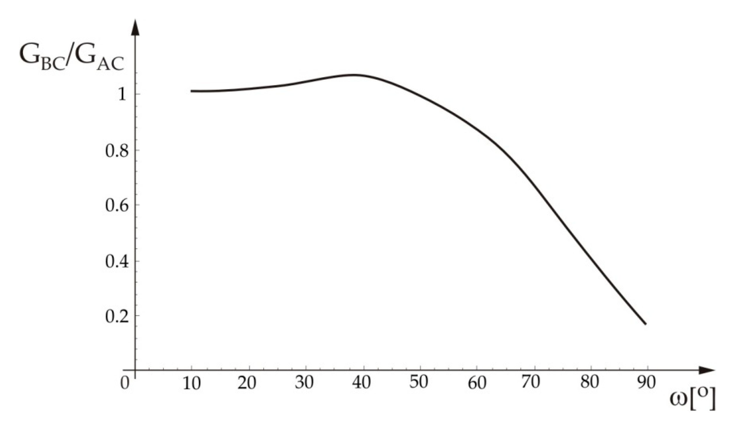
Based on Equations (1) and (6), using the
Mathematica® programming routine, the ratio of the energy release rate for the crack that propagates along the BC interface and the energy release rate for the crack that propagates along the AC interface has been calculated, and its variation in terms of angle
ω is shown in
Figure 3. For the calculations, the following data were taken into account:
εAB = 0.086,
εBC = 0.061,
εAC = 0.084, and
KAB = 1 +
i·0.672 (MPa·mm
1/2−i·0.086). It is also assumed that angle
ω varies within the interval 10° to 90° due to the physical nature of the considered problem.
From
Figure 3 it can be seen that the ratio of the energy release rates has higher values for the small values of angle
ω, while when increasing the value of the angle the ratio starts to decrease. Based on
Figure 3, one can determine whether the crack at the interface between materials A and B would deflect into the BC or AC interface. For values of the (
GBC/
GAC) ratio below the curve the crack will deflect into the interface BC, while for the values of the (
GBC/
GAC) ratio above the curve the crack will deflect into the AC interface.
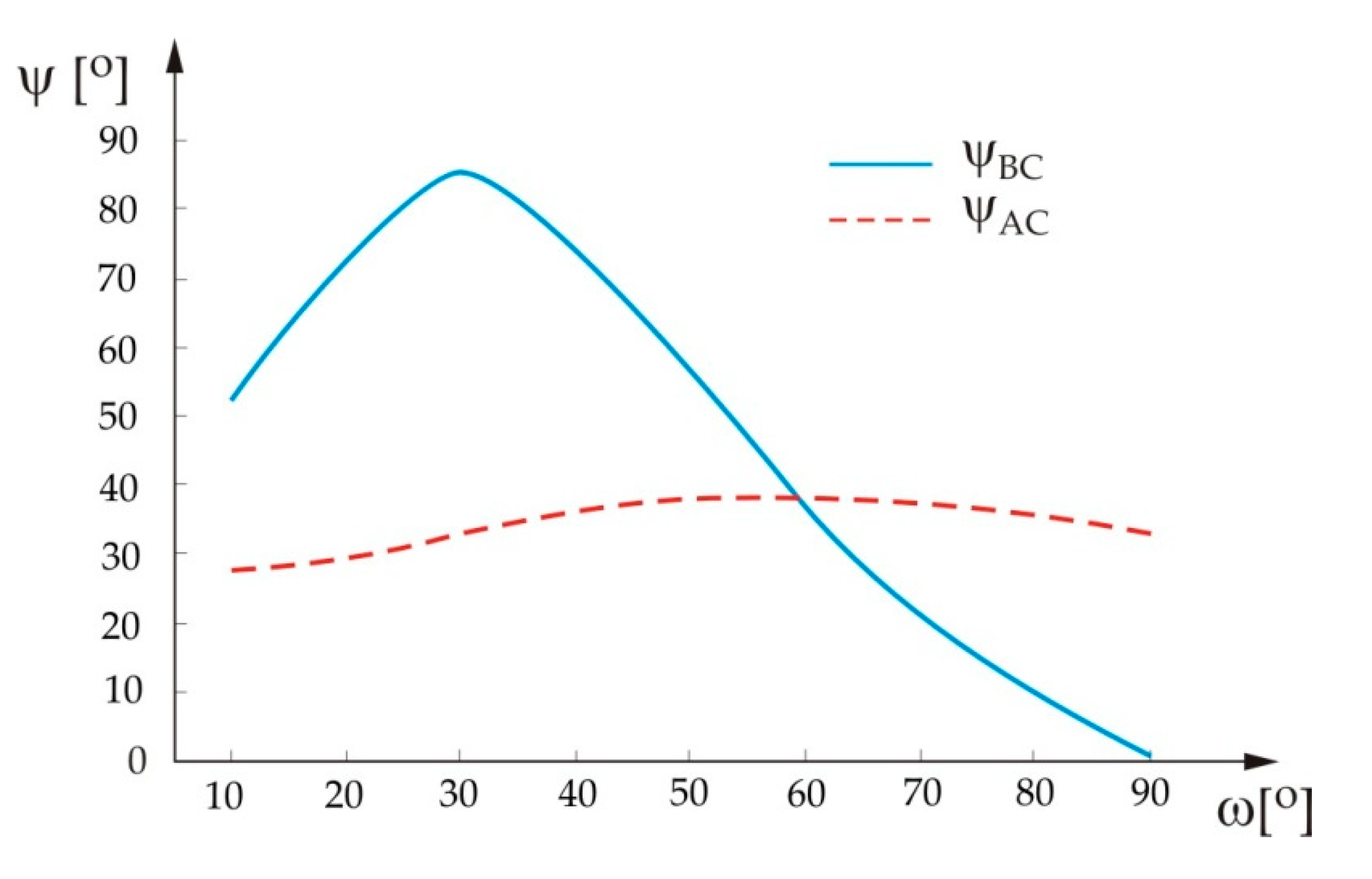
In
Figure 4 variations of the mode mixities are shown for the crack that deflects into the BC or AC interface,
ψBC or
ψAC, respectively, in terms of the angle
ω, obtained by application of the
Mathematica® programming routine.
From
Figure 4 it can be seen that for the small values of angle
ω, the mode mixity for the case of the crack deflection into the AC interface has lower values than the mode mixity for the case of the crack deflection into the BC interface. In fact, values of the mode mixity
ψAC do not vary significantly with angle
ω, which is not the case for the
ψBC mode mixity. It can be seen that this mixity’s values increase until angle
ω reaches a value of about 30°, at which point it decreases and reaches a zero value at
ω = 90°.
As mentioned, the mode mixity measures the ratio of the real and imaginary parts of the stress intensity factor. For the crack propagation along the BC interface the mode mixity increases (for up to about 30°), meaning that the imaginary part of the stress intensity factor is predominant, which would correspond to the shearing mode of the crack propagation. After reaching the maximum value, the mode mixity decreases and reaches a zero value, meaning that the share of the imaginary part of the stress intensity factor decreases, and at its zero value (for a value of the angle ω = 90°) there is only a real part of the stress intensity factor, which corresponds to a completely tearing mode of the crack propagation. For the crack propagation along the AC interface the mode mixity remains almost constant, meaning that increase of the angle ω does not influence the share of the imaginary part of the stress intensity factor, i.e., the crack propagation mode.
Variation of the real and imaginary parts of the stress intensity factors for the crack that deflects into the BC interface,
K1,BC and
K2,BC, respectively, in terms of angle
ω for the load phase angle
ψAB = 30°, was calculated based on Equation (6) by application of the programming routine
Mathematica®, with the results shown in
Figure 5. The units for
K1,BC and
K2,BC are Re(MPa·mm
1/2−i·0.061) and Im(MPa·mm
1/2−i·0.061), respectively.
From
Figure 5 it can be seen that the stress intensity factor for Mode 2 for the crack that propagates along the BC interface initially increases with increase of the angle
ω and then starts to decrease, while the stress intensity factor for Mode 1 decreases with increase of
ω. For larger values of angle
ω the real part of the stress intensity factor has negative values. This is a consequence of the possible overlap of the crack surfaces, taking into account the fact that limits on the crack surfaces were not introduced in this analysis, meaning they can deform. The overlap of the crack surfaces (actual jamming) implies that the crack would not be able to propagate along the BC interface above a value of angle
ω of approximately 40°. As mentioned, this is the consequence of the application of the LEFM restrictions related to the small plastic zone size. If these restrictions had not been taken into account, this problem would have to be considered within the framework of elastic–plastic fracture mechanics.
Variation of the real and imaginary parts of the stress intensity factors for the crack that deflects into the AC interface,
K1,AC and
K2,AC, respectively, in terms of angle
ω for the load phase angle
ψAB = 30°, was calculated based on Equation (6) by application of the programming routine
Mathematica®, with the results shown in
Figure 6. The units for
K1,AC and
K2,AC are Re(MPa·mm
1/2−i·0.084) and Im(MPa·mm
1/2−i·0.084), respectively.
From
Figure 6 it can be seen that the stress intensity factor for Mode 1, for the crack that propagates along the AC interface, initially decreases with increase of angle
ω and then starts to increase and has positive values, unlike for the case of the crack propagation along the BC interface. The stress intensity factor for Mode 2 only displays an increasing trend with increase of angle
ω. For this case of crack propagation along the AC interface, there is no overlapping (jamming) of the crack surfaces and the crack “freely” propagates along the interface with increasing load and with increasing angle
ω (this is the extension of material C).
4. Conclusions
The problem of a crack at the interface between two materials approaching a three-material joint was considered in this paper. In the case considered, the crack that lies along the interface between the two materials A and B deflects into the interface between materials A and C or into the interface between materials B and C. The criterion as to which of the two interfaces the crack deflects into is defined based on a criterion proposed by He and Hutchinson [
23].
Based on the calculations performed, the following conclusions were drawn:
A curve representing the variation (in terms of angle ω) of the ratio of the two energy release rates for the crack that deflects into the BC interface and into the AC interface (GBC/GAC) was obtained. For values of the (GBC/GAC) ratio above this curve, the crack deflects into the AC interface, and for values of the (GBC/GAC) ratio below this curve, the crack deflects into the BC interface.
Analysis of the curve that represents the variation of the mode mixity with angle of material C shows that the mode mixity for the case of crack deflection into the AC interface has lower values than the mode mixity for the case of crack deflection into the BC interface. For crack propagation along the BC interface the mode mixity increase (of up to about 30°) means that the imaginary part of the stress intensity factor is predominant, which corresponds to the shearing mode of the crack propagation. After reaching the maximum value, the mode mixity decreases and reaches a zero value, meaning that the share of the imaginary part of the stress intensity factor decreases, and at its zero value there is only a real part of the stress intensity factor, i.e., the crack propagation is completely in the tearing mode. For crack propagation along the AC interface the mode mixity remains almost constant, i.e., the share of the imaginary part of the stress intensity factor, (the crack propagation mode) remains almost the same.
Analysis of the curves that represent variation of the real and imaginary parts of the stress intensity factors for the crack that deflects into one interface or the other, in terms of angle ω, showed that the real part of the stress intensity factor for the case of crack deflection into the BC interface obtains negative values for larger values of angle ω, which be explained by possible overlap of the crack surfaces. This overlap can be explained by taking into account the LEFM restrictions on the crack surfaces. If one did not take into account these restrictions, the problem would have to be considered within the framework of elastic–plastic fracture mechanics.
For the case of crack propagation along the AC interface, there is no overlapping (jamming) of the crack surfaces and the crack is able to “freely” propagate along the interface with increasing load and angle ω (this is the extension of material C).
The presented theoretical considerations of the interface crack approaching a three-material joint could be used in trying to understand some micro-cracking phenomena during the fatigue loading of engineering materials, like steel or nodular cast iron, [
41,
42]; this might be a direction for future research.
The criterion proposed by He and Hutchinson could be used to predict the behavior of an interface crack approaching the three-material joint and to “design” interfaces between the materials to “force” the crack to deflect into one of them. This could be applied in the design of composite, cellular, or other complex materials, both at the micro and the nano levels.


