Low-Voltage Ride-Through Techniques in DFIG-Based Wind Turbines: A Review


Abstract
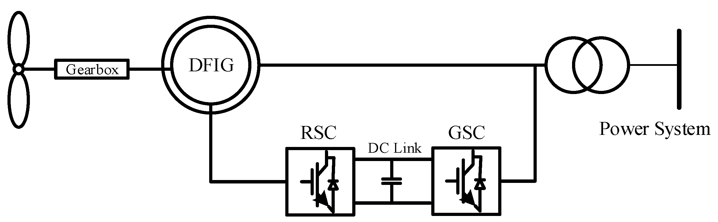
1. Introduction
2. Classification of LVRT Techniques
3. Rotor-Side External Retrofit Techniques
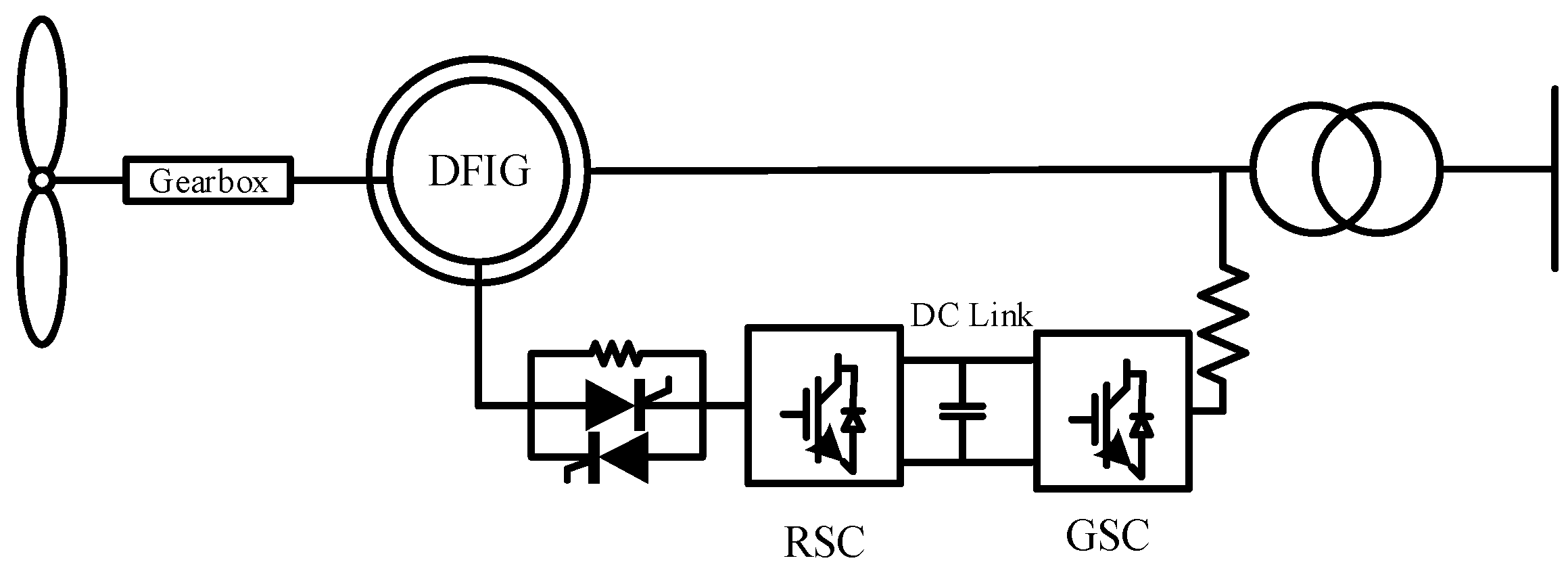
3.1. Crowbar Method
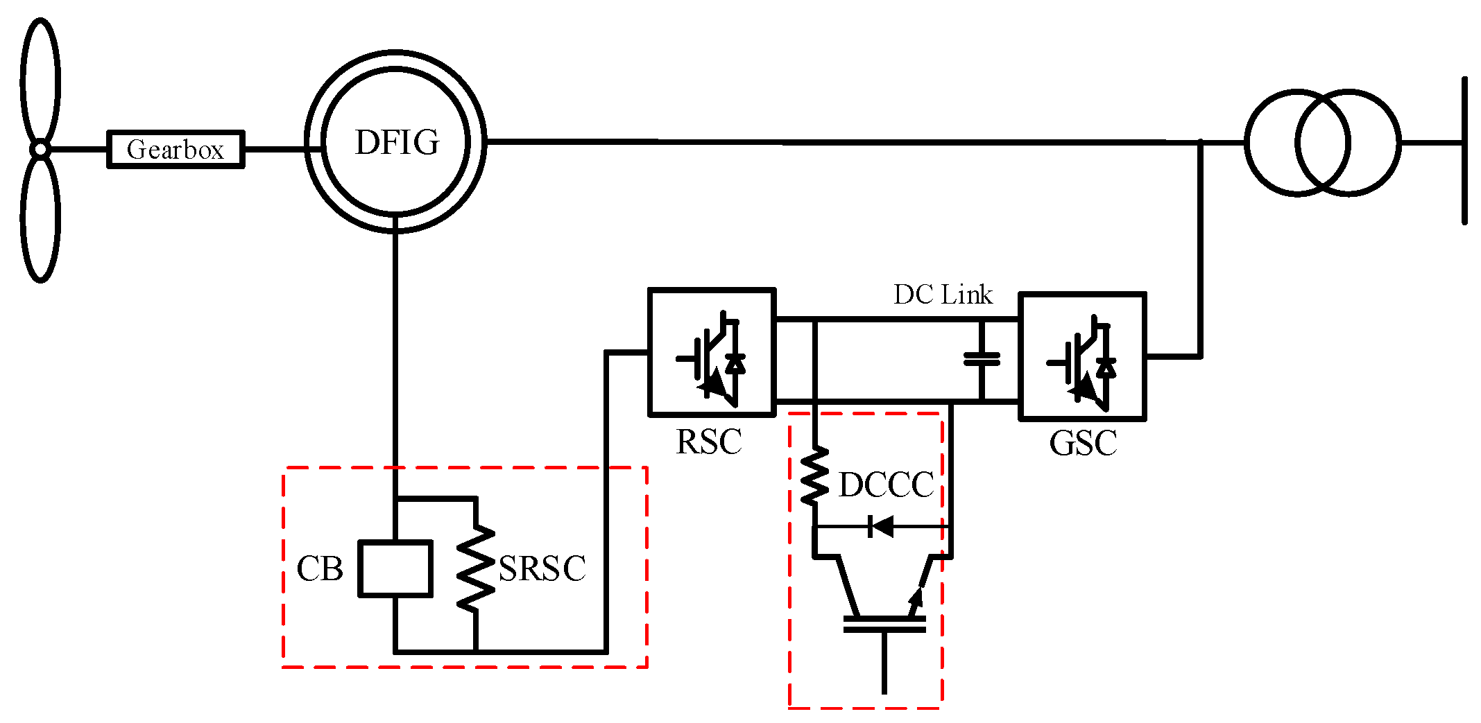
3.2. DC Chopper
3.3. Series Dynamic Resistor
3.4. DC-Link Energy Storage System
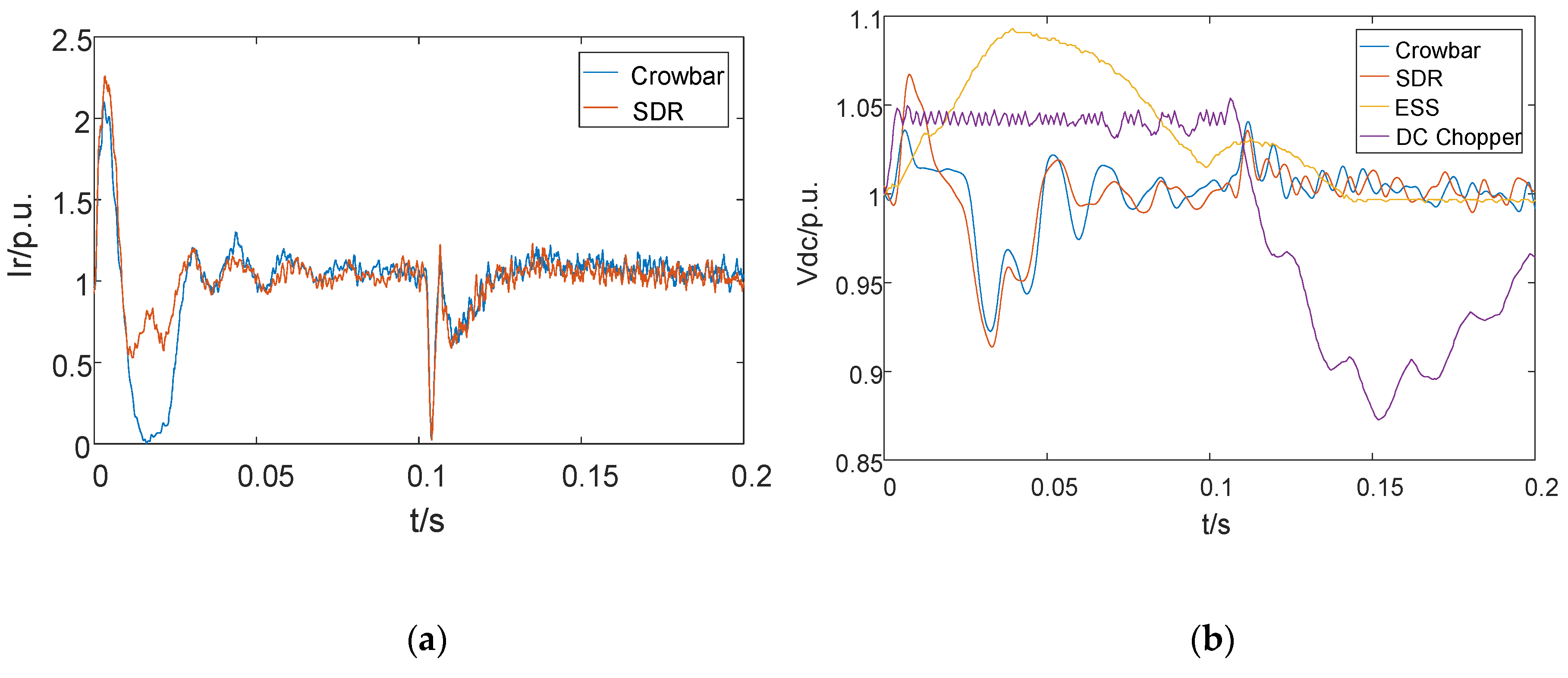
3.5. Comparative Results Analysis of Rotor-Side External Retrofit Techniques
4. Stator-Side External Retrofit Techniques
4.1. Series Dynamic Braking Resistor
4.2. Reactive Power Compensation Device
4.3. Fault Current Limiter
4.4. Series Grid-Side Converter
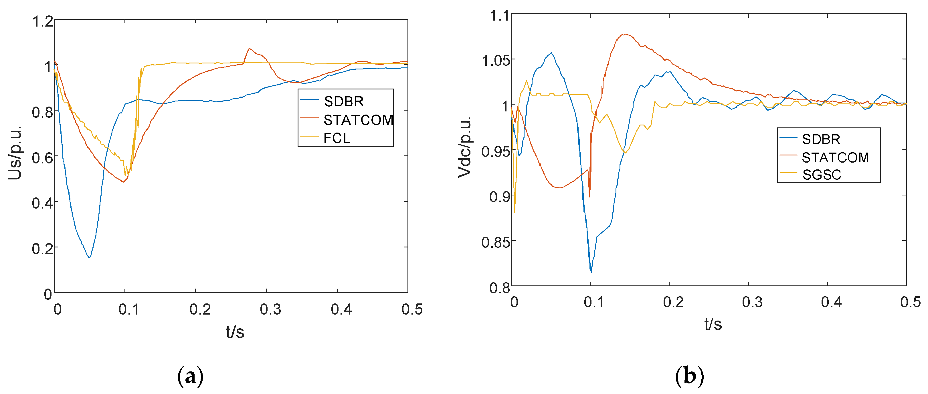
4.5. Comparative Results Analysis of Stator-Side External Retrofit Techniques
5. Internal Control Techniques
5.1. Wind Turbine Control
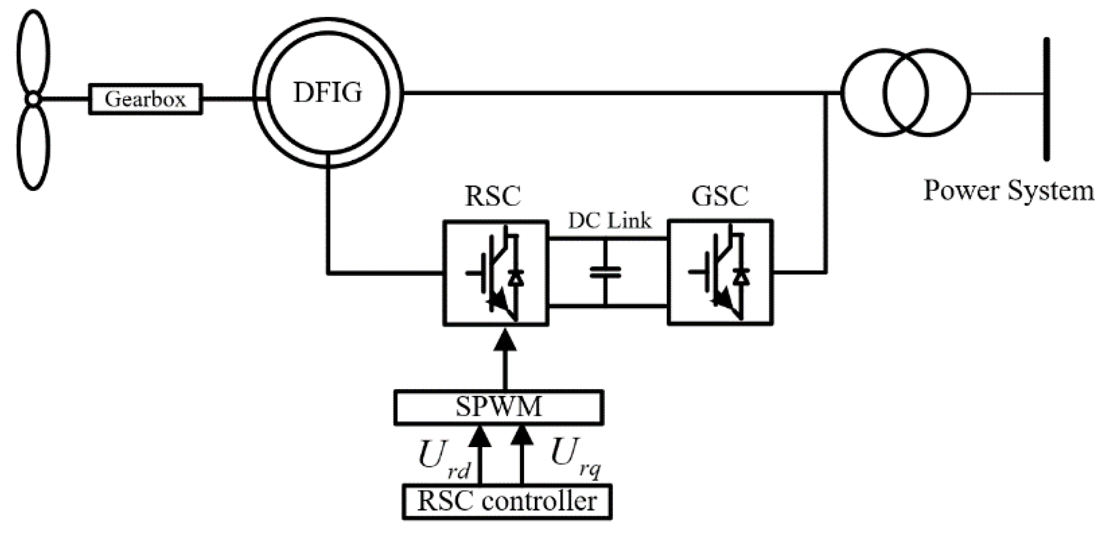
5.2. RSC Control
5.2.1. Linear RSC Control Methods
5.2.2. Nonlinear RSC Internal Control
5.3. GSC Control
5.4. Comparative Results Analysis of Internal Control Techniques
6. Conclusions and Future Trend Exploration
Author Contributions
Funding
Conflicts of Interest
References
- Jerin, A.R.A.; Kaliannan, P.; Subramaniam, U.; El Moursi, M.S. A Review on FRT solutions for improving transient stability in DFIG-WTs. IET Renew. Power Gener. 2018, 12, 1786–1799. [Google Scholar] [CrossRef]
- Kaloi, G.; Baloch, M.; Kumar, M.; Soomro, D.; Chauhdary, S.; Memon, A.; Ishak, D. An LVRT Scheme for Grid Connected DFIG Based WECS Using State Feedback Linearization Control Technique. Electronics 2019, 8, 777. [Google Scholar] [CrossRef]
- Baloch, M.H.; Ishak, D.; Chaudary, S.T.; Ali, B.; Memon, A.A.; Jumani, T.A. Wind Power Integration: An Experimental Investigation for Powering Local Communities. Energies 2019, 12, 621. [Google Scholar] [CrossRef]
- Saeed, M.A.; Khan, H.M.; Ashraf, A.; Qureshi, S.A. Analyzing effectiveness of LVRT techniques for DFIG wind turbine system and implementation of hybrid combination with control schemes. Renew. Sustain. Energy Rev. 2018, 81, 2487–2501. [Google Scholar] [CrossRef]
- Hansen, A.D.; Iov, F.; Blaabjerg, F.; Hansen, L. Review of Contemporary Wind Turbine Concepts and Their Market Penetration. Wind Eng. 2004, 28, 247–263. [Google Scholar] [CrossRef]
- Chondrogiannis, S.; Barnes, M. Stability of doubly-fed induction generator under stator voltage orientated vector control. IET Renew. Power Gener. 2008, 2, 170–180. [Google Scholar] [CrossRef]
- Rahimi, M.; Parniani, M. Grid-fault ride-through analysis and control of wind turbines with doubly fed induction generators. Electr. Power Syst. Res. 2010, 80, 184–195. [Google Scholar] [CrossRef]
- Tripathi, P.M.; Sahoo, S.S.; Chatterjee, K. Enhancing the fault ride through capability of DFIG-based wind energy system using saturated core fault current limiter. J. Eng. 2019, 2019, 4916–4921. [Google Scholar] [CrossRef]
- Mohseni, M.; Islam, S.M. Review of international grid codes for wind power integration: Diversity, technology and a case for global standard. Renew. Sustain. Energy Rev. 2012, 16, 3876–3890. [Google Scholar] [CrossRef]
- Zhang, L.; Cai, X.; Guo, J. Dynamic Responses of DFIG Fault Currents Under Constant AC Exitation Condition. In Proceedings of the 2009 Asia-Pacific Power and Energy Engineering Conference, Wuhan, China, 27–31 March 2009; pp. 1–4. [Google Scholar] [CrossRef]
- Wang, M.; Xu, W.; Jia, H.; Yu, X. A new control system to strengthen the LVRT capacity of DFIG based on both crowbar and DC chopper circuits. In Proceedings of the IEEE PES Innovative Smart Grid Technologies, Tianjin, China, 21–24 May 2012; pp. 1–6. [Google Scholar] [CrossRef]
- El Moursi, M.S.; Goweily, K.; Kirtley, J.L.; Abdel-Rahman, M. Application of Series Voltage Boosting Schemes for Enhanced Fault Ridethrough Performance of Fixed Speed Wind Turbines. IEEE Trans. Power Deliv. 2014, 29, 61–71. [Google Scholar] [CrossRef]
- Alsmadi, Y.M.; Xu, L.; Blaabjerg, F.; Ortega, A.J.; Wang, A. Comprehensive analysis of the dynamic behavior of grid-connected DFIG-based wind turbines under LVRT conditions. In Proceedings of the 2015 IEEE Energy Conversion Congress and Exposition (ECCE), Montreal, QC, Canada, 20–24 September 2015; pp. 4178–4187. [Google Scholar] [CrossRef]
- Farhadi-Kangarlu, M.; Babaei, E.; Blaabjerg, F. A comprehensive review of dynamic voltage restorers. Int. J. Electr. Power Energy Syst. 2017, 92, 136–155. [Google Scholar] [CrossRef]
- Alsmadi, Y.M.; Xu, L.; Blaabjerg, F.; Ortega, A.J.; Abdelaziz, A.Y.; Wang, A.; Albataineh, Z. Detailed Investigation and Performance Improvement of the Dynamic Behavior of Grid-Connected DFIG-Based Wind Turbines Under LVRT Conditions. IEEE Trans. Ind. Appl. 2018, 54, 4795–4812. [Google Scholar] [CrossRef]
- Niu, L.; Wang, X.; Wu, L.; Yan, F.; Xu, M. Review of low voltage ride-through technology of doubly-fed induction generator. J. Eng. 2019, 2019, 3106–3108. [Google Scholar] [CrossRef]
- Wen, H.; Cai, S. Modeling and LVRT analysis of DFIG wind power system. In Proceedings of the 2015 IEEE PES Asia-Pacific Power and Energy Engineering Conference (APPEEC), Brisbane, Australia, 15–18 November 2015; pp. 1–5. [Google Scholar] [CrossRef]
- Yang, J.; Fletcher, J.E.; O’Reilly, J. A series dynamic resistor based converter protection scheme for doubly-fed induction generator during various fault conditions. In Proceedings of the 2009 IEEE Power & Energy Society General Meeting, Calgary, AB, Canada, 26–30 July 2009; pp. 1–8. [Google Scholar] [CrossRef]
- Qin, B.; Sun, H.; Ma, J.; Li, W.; Ding, T.; Wang, Z.; Zomaya, A.Y. Robust H∞ Control of Doubly Fed Wind Generator via State-Dependent Riccati Equation Technique. IEEE Trans. Power Syst. 2019, 34, 2390–2400. [Google Scholar] [CrossRef]
- Justo, J.J.; Bansal, R.C. Parallel R-L configuration crowbar with series R-L circuit protection for LVRT strategy of DFIG under transient-state. Electr. Power Syst. Res. 2018, 154, 299–310. [Google Scholar] [CrossRef]
- Jin, C.; Wang, P. Enhancement of low voltage ride-through capability for wind turbine driven DFIG with active crowbar and battery energy storage system. In Proceedings of the IEEE PES General Meeting, Providence, RI, USA, 25–29 July 2010; pp. 1–8. [Google Scholar] [CrossRef]
- Vidal, J.; Arza, G.A.J.; Aurtenechea, S. Single-Phase DC Crowbar Topologies for Low Voltage Ride Through Fulfillment of High-Power Doubly Fed Induction Generator-Based Wind Turbines. IEEE Trans. Energy Convers. 2013, 28, 768–781. [Google Scholar] [CrossRef]
- Din, Z.; Zhang, J.; Zhu, Y.; Xu, Z.; El-Naggar, A. Impact of Grid Impedance on LVRT Performance of DFIG System with Rotor Crowbar Technology. IEEE Access 2019, 7, 127999–128008. [Google Scholar] [CrossRef]
- Guo, W.; Xiao, L.; Dai, S.; Xu, X.; Li, Y.; Wang, Y. Evaluation of the Performance of BTFCLs for Enhancing LVRT Capability of DFIG. IEEE Trans. Power Electron. 2015, 30, 3623–3637. [Google Scholar] [CrossRef]
- Okedu, K.E.; Muyeen, S.M.; Takahashi, R.; Tamura, J. Wind Farms Fault Ride Through Using DFIG With New Protection Scheme. IEEE Trans. Sustain. Energy 2012, 3, 242–254. [Google Scholar] [CrossRef]
- Islam, M.R.; Ajom, M.G.; Sheikh, M.R.I. Application of DC Chopper to Augment Fault Ride Through of DFIG Based Wind Turbine. In Proceedings of the 2017 2nd International Conference on Electrical Electronic Engineering (ICEEE), Rajshahi, Bangladesh, 27–29 December 2017; pp. 1–4. [Google Scholar] [CrossRef]
- Naderi, S.B.; Negnevitsky, M.; Muttaqi, K.M. A Modified DC Chopper for Limiting the Fault Current and Controlling the DC-Link Voltage to Enhance Fault Ride-Through Capability of Doubly-Fed Induction-Generator-Based Wind Turbine. IEEE Trans. Ind. Appl. 2019, 55, 2021–2032. [Google Scholar] [CrossRef]
- Gray, C.; Buque, C.; Chowdhury, S. AC series dynamic resistor protection scheme with switching control for doubly fed induction generator based WECS. In Proceedings of the 2016 IEEE Power and Energy Society General Meeting (PESGM), Boston, MA, USA, 17–21 July 2016; pp. 1–5. [Google Scholar] [CrossRef]
- Yang, J.; Fletcher, J.E.; O’Reilly, J. A Series-Dynamic-Resistor-Based Converter Protection Scheme for Doubly-Fed Induction Generator during Various Fault Conditions. IEEE Trans. Energy Convers. 2010, 25, 422–432. [Google Scholar] [CrossRef]
- Sun, L.; Meng, N.; Xu, B. Analysis of fault ride-through of doubly-fed wind power generator based on rotor series resistor. In Proceedings of the IECON 2016-42nd Annual Conference of the IEEE Industrial Electronics Society, Florence, Italy, 23–26 October 2016; pp. 1900–1905. [Google Scholar] [CrossRef]
- Haidar, A.M.A.; Muttaqi, K.M.; Hagh, M.T. A Coordinated Control Approach for DC link and Rotor Crowbars to Improve Fault Ride-Through of DFIG-Based Wind Turbine. IEEE Trans. Ind. Appl. 2017, 53, 4073–4086. [Google Scholar] [CrossRef]
- Kim, Y.; Zhao, J.; Harrington, R.J. Performance analysis of energy storage systems connected to a doubly fed induction generator. In Proceedings of the 2015 IEEE Green Energy and Systems Conference (IGESC), Long Beach, CA, USA, 9 November 2015; pp. 30–34. [Google Scholar] [CrossRef]
- Kim, J.; Muljadi, E.; Gevorgian, V.; Hoke, A.F. Dynamic Capabilities of an Energy Storage-Embedded DFIG System. IEEE Trans. Ind. Appl. 2019, 55, 4124–4134. [Google Scholar] [CrossRef]
- Wang, X.; Sun, D.; Zhao, C.; Nian, H.; Fan, Y. A Collaborative Control Strategy of DFIG System with Energy Storage in Weak Grid. In Proceedings of the 2019 22nd International Conference on Electrical Machines and Systems (ICEMS), Harbin, China, 11–14 August 2019; pp. 1–6. [Google Scholar] [CrossRef]
- Tourou, P.; Chhor, J.; Günther, K.; Sourkounis, C. Energy storage integration in DFIG-based wind energy conversion systems for improved fault ride-through capability. In Proceedings of the 2017 IEEE 6th International Conference on Renewable Energy Research and Applications (ICRERA), San Diego, CA, USA, 5–8 November 2017; pp. 374–377. [Google Scholar] [CrossRef]
- Shen, Y.; Ke, D.; Sun, Y.; Kirschen, D.; Qiao, W.; Deng, X. Advanced Auxiliary Control of an Energy Storage Device for Transient Voltage Support of a Doubly Fed Induction Generator. IEEE Trans. Sustain. Energy 2016, 7, 63–76. [Google Scholar] [CrossRef]
- Noureldeen, O.; Youssef, M.M.M. Constant Power-Control of DFIG Wind Farm with LVRT Improvement during Extreme Gust Using Super-Capacitors. In Proceedings of the 2018 Twentieth International Middle East Power Systems Conference (MEPCON), Cairo, Egypt, 18–20 December 2018; pp. 515–521. [Google Scholar] [CrossRef]
- Döşoğlu, M.K.; Özkaraca, O.; Güvenç, U. Novel active–passive compensator–supercapacitor modeling for low-voltage ride-through capability in DFIG-based wind turbines. Electr. Eng. 2019, 101, 1119–1132. [Google Scholar] [CrossRef]
- Hao, X.; Zhou, T.; Wang, J.; Yang, X. A hybrid adaptive fuzzy control strategy for DFIG-based wind turbines with super-capacitor energy storage to realize short-term grid frequency support. In Proceedings of the 2015 IEEE Energy Conversion Congress and Exposition (ECCE), Montreal, QC, Canada, 20–24 September 2015; pp. 1914–1918. [Google Scholar] [CrossRef]
- Alam, M.S.; Hossain, M.I.; Hossain, M.A.; Choudhory, M.S.H.; Uddin, M.A. Protection of Inverter-based Distributed Generation with Series Dynamic Braking Resistor: A Variable Duty Control Approach. In Proceedings of the 2018 10th International Conference on Electrical and Computer Engineering (ICECE), Dhaka, Bangladesh, 20–22 December 2018; pp. 253–256. [Google Scholar] [CrossRef]
- Causebrook, A.; Atkinson, D.J.; Jack, A.G. Fault Ride-Through of Large Wind Farms Using Series Dynamic Braking Resistors (March 2007). IEEE Trans. Power Syst. 2007, 22, 966–975. [Google Scholar] [CrossRef]
- Huang, P.-H.; el Moursi, M.S.; Hasen, S.A. Novel Fault Ride-Through Scheme and Control Strategy for Doubly Fed Induction Generator-Based Wind Turbine. IEEE Trans. Energy Convers. 2015, 30, 635–645. [Google Scholar] [CrossRef]
- Keshavarzi, M.D.; Ali, M.H. FRT Capability Enhancement of Autonomous AC/DC Hybrid Microgrid by Coordinated MSDBR and Interlinking Converter Control Strategy. In Proceedings of the 2019 IEEE Power Energy Society Innovative Smart Grid Technologies Conference (ISGT), Washington, DC, USA, 18–21 February 2019; pp. 1–5. [Google Scholar] [CrossRef]
- Okedu, K.E. Enhancing the performance of DFIG variable speed wind turbine using a parallel integrated capacitor and modified modulated braking resistor. Transm. Distrib. IET Gener. 2019, 13, 3378–3387. [Google Scholar] [CrossRef]
- Acha, E. Power Electronic Control in Electrical Systems; Newnes Power Engineering Series: Oxford, UK, 2002. [Google Scholar]
- Kanchanaharuthai, A.; Chankong, V.; Loparo, K.A. Transient Stability and Voltage Regulation in Multimachine Power Systems Vis-à-Vis STATCOM and Battery Energy Storage. IEEE Trans. Power Syst. 2015, 30, 2404–2416. [Google Scholar] [CrossRef]
- Li, N.; Wang, L.; Yang, H.; Ma, H. Stability Analysis for SSR of DFIG-Based Wind Farm Considering STATCOM Capacity Constraint. In Proceedings of the 2019 22nd International Conference on Electrical Machines and Systems (ICEMS), Harbin, China, 11–14 August 2019; pp. 1–6. [Google Scholar] [CrossRef]
- Molinas, M.; Suul, J.A.; Undeland, T. Low Voltage Ride Through of Wind Farms With Cage Generators: STATCOM Versus SVC. IEEE Trans. Power Electron. 2008, 23, 1104–1117. [Google Scholar] [CrossRef]
- Tang, Y.; He, H.; Ni, Z.; Wen, J.; Huang, T. Adaptive Modulation for DFIG and STATCOM With High-Voltage Direct Current Transmission. IEEE Trans. Neural Netw. Learn. Syst. 2016, 27, 1762–1772. [Google Scholar] [CrossRef] [PubMed]
- Qiao, W.; Venayagamoorthy, G.K.; Harley, R.G. Real-Time Implementation of a STATCOM on a Wind Farm Equipped With Doubly Fed Induction Generators. IEEE Trans. on Ind. Appl. 2009, 45, 98–107. [Google Scholar] [CrossRef]
- Chen, L.; Deng, C.; Zheng, F.; Li, S.; Liu, Y.; Liao, Y. Fault Ride-Through Capability Enhancement of DFIG-Based Wind Turbine with a Flux-Coupling-Type SFCL Employed at Different Locations. IEEE Trans. Appl. Supercond. 2015, 25, 1–5. [Google Scholar] [CrossRef]
- Lim, S.; Ahn, H.; Park, C. Study on Fault Current Limiting Characteristics of an SFCL Using Magnetic Coupling of Two Coils With Mechanical Switch Driven by Electromagnetic Repulsion Force. IEEE Trans. Appl. Supercond. 2014, 24, 1–4. [Google Scholar] [CrossRef]
- Sedighizadeh, M.; Yarmohammadi, H.; Esmaili, M. Enhancing FRT performance and smoothing output power of DFIG wind farm equipped by SFCL and SMES in a fuzzy framework. Eng. Sci. Technol. Int. J. 2019, 22, 801–810. [Google Scholar] [CrossRef]
- Ngamroo, I.; Karaipoom, T. Improving Low-Voltage Ride-Through Performance and Alleviating Power Fluctuation of DFIG Wind Turbine in DC Microgrid by Optimal SMES With Fault Current Limiting Function. IEEE Trans. Appl. Supercond. 2014, 24, 1–5. [Google Scholar] [CrossRef]
- Gontijo, G.F.; Cardoso, T.T.; Francisco, D.T.; Krejci, D.; França, B.W.; Aredes, M.; Guerrero, J.M. Modeling, Control and Experimental Verification of a DFIG with a Series-Grid-Side Converter with Voltage Sag, Unbalance and Distortion Compensation Capabilities. IEEE Trans. Ind. Appl. 2019, 56, 584–600. [Google Scholar] [CrossRef]
- Yao, J.; Li, H.; Chen, Z.; Xia, X.; Chen, X.; Li, Q.; Liao, Y. Enhanced Control of a DFIG-Based Wind-Power Generation System with Series Grid-Side Converter under Unbalanced Grid Voltage Conditions. IEEE Trans. Power Electron. 2013, 28, 3167–3181. [Google Scholar] [CrossRef]
- Omar, S.; Helal, A.; Elarabawy, I. Stator voltage sensorless DFIG with low voltage ride-through capability using series and parallel grid side converters. In Proceedings of the 2016 7th International Renewable Energy Congress (IREC), Hammamet, Tunisia, 22–24 March 2016; pp. 1–6. [Google Scholar] [CrossRef]
- Flannery, P.S.; Venkataramanan, G. Unbalanced Voltage Sag Ride-Through of a Doubly Fed Induction Generator Wind Turbine with Series Grid-Side Converter. IEEE Trans. Ind. Appl. 2009, 45, 1879–1887. [Google Scholar] [CrossRef]
- Gontijo, G.; Tricarico, T.; Krejci, D.; França, B.; Aredes, M. A novel stator voltage distortion and unbalance compensation of a DFIG with series grid side converter using adaptive resonant controllers. In Proceedings of the 2017 Brazilian Power Electronics Conference (COBEP), Juiz de Fora, Brazil, 19–22 November 2017; pp. 1–6. [Google Scholar] [CrossRef]
- Flannery, P.S.; Venkataramanan, G. A Fault Tolerant Doubly Fed Induction Generator Wind Turbine Using a Parallel Grid Side Rectifier and Series Grid Side Converter. IEEE Trans. Power Electron. 2008, 23, 1126–1135. [Google Scholar] [CrossRef]
- Elnaghi, B.E.; Dessouki, M.E.; Elkader, F.A. Experimental investigation of pitch angle controller for DFIG based wind energy conversion system. In Proceedings of the 2017 Nineteenth International Middle East Power Systems Conference (MEPCON), Cairo, Egypt, 19–21 December 2017; pp. 1477–1482. [Google Scholar] [CrossRef]
- Zhang, Y.; Muljadi, E.; Kosterev, D.; Singh, M. Wind Power Plant Model Validation Using Synchrophasor Measurements at the Point of Interconnection. IEEE Trans. Sustain. Energy 2015, 6, 984–992. [Google Scholar] [CrossRef]
- Ali, M.M.M.; Youssef, A.-R.; Abdel-Gaber, G.; Ali, A.S. Adaptive Fuzzy-PID Based Pitch Angle Control of Wind Turbine. In Proceedings of the 2018 Twentieth International Middle East Power Systems Conference (MEPCON), Cairo, Egypt, 18–20 December 2018; pp. 1110–1114. [Google Scholar] [CrossRef]
- Guo, F.; Zheng, T.; Wang, Z. Comparative study of direct power control with vector control for rotor side converter of DFIG. In Proceedings of the 9th IET International Conference on Advances in Power System Control, Operation and Management (APSCOM 2012), Hong Kong, China, 18–21 November 2012; pp. 1–6. [Google Scholar] [CrossRef]
- Yang, L.; Xu, Z.; Ostergaard, J.; Dong, Z.; Wong, K.P. Advanced Control Strategy of DFIG Wind Turbines for Power System Fault Ride Through. IEEE Trans. Power Syst. 2012, 27, 713–722. [Google Scholar] [CrossRef]
- Mohammadi, J.; Vaez-Zadeh, S.; Afsharnia, S.; Daryabeigi, E. A Combined Vector and Direct Power Control for DFIG-Based Wind Turbines. IEEE Trans. Sustain. Energy 2014, 5, 767–775. [Google Scholar] [CrossRef]
- Ruiz-Cruz, R.; Sanchez, E.N.; Ornelas-Tellez, F.; Loukianov, A.G.; Harley, R.G. Particle Swarm Optimization for Discrete-Time Inverse Optimal Control of a Doubly Fed Induction Generator. IEEE Trans. Cybern. 2013, 43, 1698–1709. [Google Scholar] [CrossRef]
- Chen, J.; Xue, A.; Tian, C.; Bi, T.; Gao, C. A new method to improve the LVRT of DFIG based on the current compensation. In Proceedings of the 30th Chinese Control Conference, Yantai, China, 22–24 July 2011; pp. 5148–5152. [Google Scholar]
- Liu, R.; Yao, J.; Wang, X.; Sun, P.; Pei, J.; Hu, J. Dynamic Stability Analysis and Improved LVRT Schemes of DFIG-Based Wind Turbines during a Symmetrical Fault in a Weak Grid. IEEE Trans. Power Electron. 2020, 35, 303–318. [Google Scholar] [CrossRef]
- Liang, J.; Howard, D.F.; Restrepo, J.A.; Harley, R.G. Feedforward Transient Compensation Control for DFIG Wind Turbines during both Balanced and Unbalanced Grid Disturbances. IEEE Trans. Ind. Appl. 2013, 49, 1452–1463. [Google Scholar] [CrossRef]
- Zhu, D.; Zou, X.; Zhou, S.; Dong, W.; Kang, Y.; Hu, J. Feedforward Current References Control for DFIG-Based Wind Turbine to Improve Transient Control Performance During Grid Faults. IEEE Trans. Energy Convers. 2018, 33, 670–681. [Google Scholar] [CrossRef]
- Liang, J.; Qiao, W.; Harley, R.G. Feed-Forward Transient Current Control for Low-Voltage Ride-Through Enhancement of DFIG Wind Turbines. IEEE Trans. Energy Convers. 2010, 25, 836–843. [Google Scholar] [CrossRef]
- Chen, S.; Cheung, N.C.; Wong, K.; Jie, W. Integral Sliding-Mode Direct Torque Control of Doubly-Fed Induction Generators under Unbalanced Grid Voltage. IEEE Trans. Energy Convers. 2010, 25, 356–368. [Google Scholar] [CrossRef]
- Wu, F.; Zhang, X.-P.; Ju, P.; Sterling, M.J.H. Decentralized Nonlinear Control of Wind Turbine with Doubly Fed Induction Generator. IEEE Trans. Power Syst. 2008, 23, 613–621. [Google Scholar] [CrossRef]
- Qin, B.; Zhang, X.; Ma, J.; Deng, S.; Mei, S.; Hill, D.J. Input-to-State Stability Based Control of Doubly Fed Wind Generator. IEEE Trans. Power Syst. 2018, 33, 2949–2961. [Google Scholar] [CrossRef]
- Qin, B.; Sun, H. State Dependent Riccati Equation Based Rotor-Side Converter Control for Doubly Fed Wind Generator. IEEE Access 2018, 6, 27853–27863. [Google Scholar] [CrossRef]
- Lu, Y. Adaptive-Fuzzy Control Compensation Design for Direct Adaptive Fuzzy Control. IEEE Trans. Fuzzy Syst. 2018, 26, 3222–3231. [Google Scholar] [CrossRef]
- Djeridane, M.E.; Mechgoug, R.; Ajgou, R.; Chemsa, A. Fuzzy Rotor Side Control of a DFIG-Based Wind Turbine. In Proceedings of the 2018 International Conference on Communications and Electrical Engineering (ICCEE), El Oued, Algeria, 17–18 December 2018; pp. 1–7. [Google Scholar] [CrossRef]
- Raju, S.K.; Pillai, G.N. Design and Implementation of Type-2 Fuzzy Logic Controller for DFIG-Based Wind Energy Systems in Distribution Networks. IEEE Trans. Sustain. Energy 2016, 7, 345–353. [Google Scholar] [CrossRef]
- Hu, J.; He, Y.; Xu, L.; Williams, B.W. Improved Control of DFIG Systems During Network Unbalance Using PI–R Current Regulators. IEEE Trans. Ind. Electron. 2009, 56, 439–451. [Google Scholar] [CrossRef]
- Hu, J.; Xu, H.; He, Y. Coordinated Control of DFIG’s RSC and GSC under Generalized Unbalanced and Distorted Grid Voltage Conditions. IEEE Trans. Ind. Electron. 2013, 60, 2808–2819. [Google Scholar] [CrossRef]
- Ruiz-Cruz, R.; Sanchez, E.N.; Loukianov, A.G.; Ruz-Hernandez, J.A. Real-Time Neural Inverse Optimal Control for a Wind Generator. IEEE Trans. Sustain. Energy 2019, 10, 1172–1183. [Google Scholar] [CrossRef]
- Rahimi, M.; Parniani, M. Coordinated Control Approaches for Low-Voltage Ride-Through Enhancement in Wind Turbines With Doubly Fed Induction Generators. IEEE Trans. Energy Convers. 2010, 25, 873–883. [Google Scholar] [CrossRef]


| Active Power Support | Reactive Power Support | DC-Link Voltage Oscillations | High DC-Link Voltage | Rotor Voltage Oscillations | Stator Voltage Oscillations | Rotor Current Oscillations | Stator Current Oscillations | High Rotor Voltage | High Rotor Current | High Stator Current | LVRT Capacity Technique | |
|---|---|---|---|---|---|---|---|---|---|---|---|---|
| − | * | − | √ | − | * | √ | − | − | √ | − | Rotor crowbar | |
| − | − | √ | √ | − | − | − | − | − | * | − | DC-chopper | |
| − | √ | − | √ | − | √ | − | − | √ | √ | − | Series dynamic resistor | |
| √ | √ | √ | √ | − | √ | * | √ | − | * | √ | Energy storage system | |
| − | − | √ | √ | − | √ | − | − | √ | − | − | Series dynamic | braking resistor |
| − | √ | √ | √ | − | √ | − | * | − | − | * | STATCOM | |
| − | − | − | − | − | √ | − | − | − | − | √ | Fault current limiter | |
| √ | − | √ | √ | − | √ | − | − | − | − | − | Series grid side converter | |
| Active Power Support | Reactive Power Support | DC-Link Voltage Oscillations | High DC-Link Voltage | Rotor Voltage Oscillations | Stator Voltage Oscillations | Rotor Current Oscillations | Stator Current Oscillations | High Rotor Voltage | High Rotor Current | High Stator Current | LVRT Capacity Technique |
|---|---|---|---|---|---|---|---|---|---|---|---|
| * | * | √ | √ | √ | √ | √ | √ | √ | √ | √ | BPA control |
| − | − | √ | √ | − | − | √ | √ | − | √ | − | Vector control |
| − | − | √ | √ | √ | √ | − | √ | √ | − | − | CC control |
| √ | √ | − | − | − | − | √ | − | − | √ | − | Feedforward control |
| − | − | − | − | − | − | √ | √ | √ | √ | − | SMC control |
| √ | √ | − | − | √ | √ | √ | √ | − | − | − | DNC control |
| √ | √ | − | − | √ | √ | √ | √ | √ | − | − | ISS control |
| √ | √ | − | − | √ | √ | √ | √ | √ | √ | − | SDRE control |
| − | − | √ | √ | − | − | √ | √ | − | √ | √ | Fuzzy control |
| √ | − | − | − | − | − | √ | √ | − | − | √ | PI-R control |
| √ | − | √ | √ | − | − | √ | √ | − | − | √ | PI-DFR control |
| − | − | √ | √ | − | − | − | − | − | − | − | RNIO |
| − | − | − | √ | − | − | − | − | − | √ | − | -coordinated control in Reference [83] |
© 2020 by the authors. Licensee MDPI, Basel, Switzerland. This article is an open access article distributed under the terms and conditions of the Creative Commons Attribution (CC BY) license (http://creativecommons.org/licenses/by/4.0/).
Share and Cite
Qin, B.; Li, H.; Zhou, X.; Li, J.; Liu, W. Low-Voltage Ride-Through Techniques in DFIG-Based Wind Turbines: A Review. Appl. Sci. 2020, 10, 2154. https://doi.org/10.3390/app10062154
Qin B, Li H, Zhou X, Li J, Liu W. Low-Voltage Ride-Through Techniques in DFIG-Based Wind Turbines: A Review. Applied Sciences. 2020; 10(6):2154. https://doi.org/10.3390/app10062154
Chicago/Turabian StyleQin, Boyu, Hengyi Li, Xingyue Zhou, Jing Li, and Wansong Liu. 2020. "Low-Voltage Ride-Through Techniques in DFIG-Based Wind Turbines: A Review" Applied Sciences 10, no. 6: 2154. https://doi.org/10.3390/app10062154
APA StyleQin, B., Li, H., Zhou, X., Li, J., & Liu, W. (2020). Low-Voltage Ride-Through Techniques in DFIG-Based Wind Turbines: A Review. Applied Sciences, 10(6), 2154. https://doi.org/10.3390/app10062154