Article

Improving the Performance of Doubly Fed Induction Generator Using Fault Tolerant Control—A Hierarchical Approach

1
Faculty of Automation, Huaiyin Institute of Technology, Huai’an 223003, China
2
Department of Electrical and Electronic Engineering, University of Kerbala, Kerbala 56001, Iraq
3
Jiangsu Smart Factory Engineering Research Centre, College of Management and Engineering, Huaiyin Institute of Technology, Huai’an 223003, China
4
School of Electronics and Information Engineering, Huaiyin Institute of Technology, Huai’an 223003, China
*
Authors to whom correspondence should be addressed.
Appl. Sci. 2020, 10(3), 924; https://doi.org/10.3390/app10030924
Submission received: 11 December 2019 / Revised: 22 January 2020 / Accepted: 23 January 2020 / Published: 31 January 2020
(This article belongs to the Special Issue Wind Power Systems: Design, Operation, and Control)

Abstract

:
The growth of using wind energy on a large scale increases the demand for wind energy conversion machines (WECMs), among these converters, the doubly-fed induction generator (DFIG) is the favorite choice. However, DFIG is very sensitive to wind speed variations and grid faults during operation. In order to overcome these undesirable characteristics, this paper proposes a hierarchical fault tolerant control (FTC) to improve the performance of DFIG. The hierarchical fault tolerant control (FTC) approach consists of pitch angle control (PAC) and maximum power point tracking (MPPT). This hierarchical approach demonstrates the robust response under various (low, rated, and high) wind speed ranges and reduces the undesirable DC voltage overshoots during short-circuit disorder. The simulation results are summarized in a logical table, which depicts the order of controlling scheme and operation for a sustainable energy generation system. The proposed control scheme achieved the healthy and the robust dynamic response without deteriorating the grid power quality or stressing the converters, and approved the effectiveness to suppress the DC voltage overshoots and tolerate the lower down short-circuit disorder to its rated range.

1. Introduction

In many countries, wind is the prominent source of new energy and has become the beneficiary to develop their economies with different energy conversion machines such as the double fed induction generator (DFIG) [1,2,3,4,5]. The increase in the number of energy converters and their sizes demanded by industry opens up the way to build new burning designs and protection schemes [6,7,8,9,10]. Modern wind energy conversion systems (WECSs) rely on doubly fed induction generators (DFIGs) in order to fulfil the energy demands efficiently [11,12]. The industry users and researchers have observed multiple benefits of this kind of machine, such as better control competency, low maintenance and inverter cost, robustness, and a comparatively higher power-size.
In the concept of DFIG wind turbines, the rotor is linked to the grid through a moderately rated frequency converter, while the stator of the generator is directly coupled to the power grid [10]. The size and costs of the power electronic components are comparatively smaller than full-power converters, as the deployment of DFIGs in wind turbines has been the preferred choice. However, the concept to the network voltage dips response is observed to be challenging. The wind generation penetration has gained a remarkable level in a number of areas. The wind turbines in such zones are not certified to operate independently from the main power network. The power network stability may be threatened if wind turbines are cut off as a result of a voltage dip or wind speed variations [13]. The main operating system requires grid codes that maintain the wind turbines to be capable of tolerating during deep voltage dips. This situation is considered as fault-tolerant control in power grid operation [9,14]. Furthermore, in order to support the grid voltage, the grid codes required that wind turbines must be able to penetrate reactive power to the power network under the voltage dip condition [15]. The wind turbine units under grid disturbances are considered as the fault ride-through (FRT), and the ability to overcome these undesirable conditions is referred to as the FRT capability of the power grid [13].
The short-circuit faults (balanced and unbalanced) [12,16], speed sensors faults [17], DC voltage overshoot faults [10,18], and grid faults and actuator faults [9,19,20,21,22] are subjected to the DFIG. Multiple kinds of techniques [9,23,24] are applied and analyzed to overcome these thresholds and voltage overshoot faults [25,26]. If a balanced or an unbalanced voltage overshoot fault occurs in the DFIG power system, the system will depreciate the performance, and this influence may lead to the unscheduled shutdown of the power system and disconnection to the power grid. Therefore, DC voltage overshoot fault-tolerant control (DC-FTC) has been gaining increasing attention in the development of the reliability of the DFIG system. Fault current limiting approaches are one of the techniques utilized to limit the current level and protect the back-to-back converter switchings from over-current damage [27]. To reach this goal, DFIGs’ active power output must be controlled within the limit of the operating conditions using a maximum power point tracking (MPPT) controller [10,28]. In the literature, FTC-based strategies on different control schemes have been recommended numerous times, including linear-quadratic, pseudo-inverse fuzzy logic, electromechanical faults, intelligent control FTC based on proportional internal control, dynamic inversion, command governor, neural network, and variable structure control, as well as methods based on the combination of different approaches [29,30]. It is widely used in multiple power generations systems including wind turbines with rotor speed sensor and pitch angle sensor faults [3]. These stratagems focus on the characteristics of multiple power systems including wind turbine systems. Meanwhile, in the dynamics of DFIG and the combination of DC voltage overshoots, pitch angle control (PAC) and MPPT strategies to control the faults are not considered. The authors of [10] investigated the DC voltage overshoots of DFIG based wind turbines. In short-circuit conditions, the overshoot of DC voltage leads to the disconnectivity of the grid as well as converter instability. To overcome these DC voltage overshoots, special measurement and standard limits to control these DC voltage overshoots and contravene of grid operation are still needed. An understanding between power engineers and wind industry developers is the preliminary requirement for an efficient wind energy system.
This paper introduces a combination of pitch angle and maximum power point tracking controllers to deal with DC voltage overshoots, and keeps the faulty conditions close to its rated values during short-circuits. Furthermore, it achieves the maximum power tracking under low and rated wind speeds, as well as regulates the pitch angle once there is a high wind speed condition. In this case, firstly, a short-circuit is detected as the fault, and then the PWM pulses for a rotor side converter (RSC) are generated by controlling the modulation indices. The reason for decreasing the indices is to keep the DC voltage level to its rated value under the fault condition. The control signal during a fault for MPPT is measured as zero. This value increased to one after completely removing the fault. This status is maintained by the proposed controller scheme. The controller operates in a special logical technique under different wind variations, that is, normal or healthy and abnormal or faulty operation conditions, including MPPT-based tracking optimal tip speed ration (TSR) by adjusting the rotor speeds.

2. Related Work

2.1. DC Voltage Overshoots

The problem of a fault is investigated and the FTC scheme is applied to stabilize the DC voltage overshoots during the short-circuit condition of WECS. The DC overshoot value is measured as severe and active (Ps), and reactive (Qs) power values are similarly observed to erupt at grid side converter (GSC) of WECS. An FTC scheme is developed to suppress the DC overshoots under the short-circuit conditions of the power system.
While faults occur in the system at the grid side, for the line side converter (LSC), the power transformation will be interrupted. Hence, the wind farms’ production ought to be imperfect to confirm the protection of the DC link voltage. The proposed technique establishes communication among both sides to prevent the DC voltage from increasing to its rated rates. The method of this procedure relies on the stability of the DC voltage. Unambiguously, in healthy operational environments, the DC voltage is observed to be constant and close to its rated value. However, under the faulty conditions, it is abrupt and rises toward an undesirable value. For this objective, a block is developed to calculate the DC voltage and determine its rate of variation. Once the fault happens at the AC grid side in the system, the DC voltage increased owing to the uninterrupted energy transfer from the wind farms’ side. The authors of [15,31,32] studied other different kinds of controllers and investigated the improvement of the performance of the DFIG system and synchronization with the grid.
It is worth noting that AC–DC grid converters deteriorate from two frequency ripples in the active power and the DC-link voltage during faults. In this paper, the active component current (i.e., the d-axis current id) is appointed to control the DC-link voltage according to the following control loop in Equation (1):
i d = k p 1 ( V d c V d c ) + k i 1 s ( V d c V d c )
where Vdc is the DC-link voltage and kp1 and ki1 are the proportional and integral gains for the DC-link voltage control loop, respectively. Meanwhile, the reactive component current (i.e., the q-axis current iq) provides a rapid reactive injection current during faults. The control loop of the reactive injection current is represented as follows in Equation (2):
i q = k p 2 ( V g V g ) + k i 2 s ( V g V g ) + i q _ i n j
where Vg is the RMS grid voltage; kp2 and ki2 are the proportional and integral gains for the reactive injection current control loop, respectively; and iq_inj is the amount of reactive injection current to the grid during short circuits. The latter control loop is activated when the grid voltage drops to lower than the 0.5 p.u. threshold.

2.2. Fault Tolerant Control (FTC)

Fault tolerant control (FTC) schemes are widely used in all kind of industries, including renewable power systems (nuclear, solar, and wind), aircraft, helicopters, and spacecraft. The structures include highway systems, automotive systems, engine and propulsion control, chemical plants, robots, building and air-conditions systems, industrial furnaces and heat exchanger, drug infusion, motors and drives, networks, paper machines, magnetic bearing systems, winding machines, and water-tank systems [9,33,34]. The FTC scheme not only deals with wind perturb conditions, but reduces the short-circuit overshoots disorder and applies the MPPT strategy to ensure the healthy operation of the DFIG-WT-based power system. In addition, the FTC scheme has been applied to ensure the smooth healthy operation of DFIG and grid connectivity under various wind speeds and short-circuit faults [20,25,35].

2.3. Pitch Angle Control (PAC)

PAC is a useful technique for power adjustment, exceeding the rated wind speed. It is measured as the most effectual and prevalent power control technique. The conventional pitch controls the typically practiced PI controller, and the system must be acknowledged well by means of a mathematical model. In this paper, we deal through the process and the control of the DFIG power generation at different approaches. The purpose of applying PAC is expressed as follows.
Firstly, to optimize the wind turbines’ output power and lower-rated wind speed, the pitch adjustment must be at its optimal rate to provide the maximum power. Secondly, in order to reduce the load fatigue of the mechanical parts of the turbine, it has been experienced that the turbine’s control system can have a major influence on the loads [10]. The controllers need to ensure that excessive loads will not affect the control action; the strategy of the controller has to take into account the effect on loads. It is possible to go further than this, and explicitly design the controller with the reduction of definite lethargy loads as an additional objective. Thirdly, the design limits for preventing the input mechanical power must be dealt with. Above rated wind speed, pitch angle control provides an operative technique of maintaining the aerodynamic command and loads produced by the rotor.
In the case of the variable-speed wind turbine, a mechanical actuator is commonly employed to regulate the pitch angle of the blades for the sake of reducing the power coefficient (Cp) and sustaining the power at its rated rate. For linearization of the model, the torque is acknowledged as being proportional to the gyratory rate of the turbine [1,35]. The control approach is implemented as follows, in Equations (3) and (4), where β is the rotor blades’ angle and ω is the rotor speed of the turbine:
β r e f = β 0 = 0 ,   for   0   <   ω t   <   ω tn
β r e f = Δ β Δ ω ( ω t ω t n ) + β 0 ,   for   ω t   >   ω tn
It is depicted that the optimal value of the tip speed ratio (λ) is 10, which keeps Cp at its maximum value, that is, 0.5 p.u.

2.4. Maximum Power Point Tracking (MPPT) Approach

The lookup table-based MPPT approach uses the tip speed ration (TSR) to control the DFIG-based wind power system [1,16]. This technique is based on changing the range of rotor speeds of the DFIG system. In order to follow the reference rotor speed, this varies with wind speed. The reference speed ensures the optimal TSR that brings the power coefficient (Cp) of the wind turbine to its maximum value. The MPPT control-based TSR controller is presented.
An extra anemometer is required to apply this scheme for the wind speed measurement and also has a pre-known value of the optimal TSR to convert the wind velocity measurement into its corresponding reference for optimal generator speed. Owing to the non-negligible inertia of WECS, the generator speed changes rather lethargically as compared with the change in the wind rate. On the other side, the TSR control technique provides the fastest control action as it directly measures the wind speed and provides the control reference instantaneously. Therefore, it gives more energy. Although, accurate wind measurement is not a small task, especially in the case of the large wind turbine. The anemometer provides limited measurements of wind speed only at the hub height and cannot cover for the whole span of large blades [36]. In addition, owing to the interaction between the rotor and the wind, this usual placement of anemometers on nacelles leads to inaccurate wind speed measurements in both upwind and downwind turbines. For TSR control, we keep the TSR constant at its optimal value by changing the rotor speed in the numerator. Meanwhile, the wind speed changed in the denominator of the above ratio. The generated power by the wind turbine is mathematically expressed as follows:
P = 0.5ρπ R2V3Cp (λ, β)
where ρ is the air density (kg/m3), R is the radius of the turbine rotor, V denotes the speed of the wind, and Cp represents the power coefficient that shows the power conversion efficiency of the wind turbine. The theoretical power available in the wind is the physical meaning of the Cp curve; this is the ratio of the actual power delivered by the turbine. Cp is a function of the TSR, λ, in addition to the blade pitch angle (β) in a pitch-controlled wind turbine. The value of λ is given in Equation (6).
λ = Rωr/V
where ωr is the rotating speed of the wind turbine. Practically, the maximum Cp can be 40%–45% [36]. The rotor proficiency curve CP (λ) is a nonlinear function of the TSR (λ), which is indomitable by the blade design and the pitch angle. The relationship between Cp and TSR can also be summarised as follows: TSR = ωr*R/Vwind, where R is the radius of the blade.

3. Proposed Model

The proposed FTC scheme is applied to suppress the overshoot DC voltage under the perturbation condition of the system. A balanced short-circuit (SC) fault is applied to test the validity of the proposed FTC scheme. The short circuit is applied in the premeditated system at GSC.
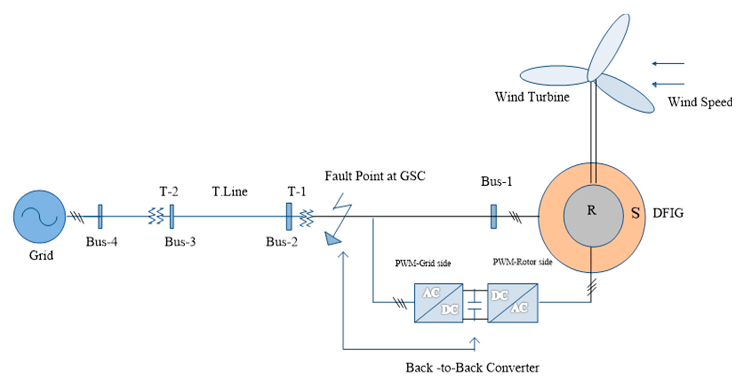
The conditions and standard measurements are arranged and observed in the SC, and then the FTC algorithm values are tuned according to the acceptable system values. The FTC algorithm performance is appreciated under the balanced SC depicted in Figure 1. It reduces the SC and holds it within the minimum value. This response is favorable for system protection. Figure 2 shows the DFIG testing block diagram, which consists of the power grid; four busses, bus-1 to bus-4; two transformers, T-1 and T-2; the transmission line, T-line; and the fault point at grid side converters.
The DFIG model designed and presented in Figure 2 is a state-space based model. In the alpha–beta (α–β) stationary reference frame, the DFIG model can be represented in the state-space form as follows:
x . ( t ) = A x ( t ) + B u ( t ) y ( t ) = C x ( t )
where x = [ I α s I β s I α r i β r ] T is the rotor and stator current component; and u (t) is the system input, which can be written as x = [ u α s u β s u α r u β r ] T , which is the rotor and the stator voltage components. Hence, the state matrix A and the matrix input B are defined as follows in Equation (8):
A = ( A 11 A 12 A 21 A 22 ) , B = ( L m σ L s L r I 2 1 σ L s I 2 1 σ L r I 2 L m σ L s L r I 2 ) , K = ( 0 1 1 0 )
where
A 11 = ( R s σ L s I 2 + ( ω s + L m 2 P Ω m e c h σ L s L r ) K )
A 12 = ( L m R r σ L s L r I 2 L m P Ω m e c h σ L s K )
A 21 = ( L m R s σ L s L r I 2 + L m P Ω m e c h σ L r K )
A 22 = ( 1 σ L r I 2 + ( ω s P Ω m e c h σ ) K )
Calculating   σ   as   σ = 1 L m 2 / ( L s L r )
The rotor and stator resistances are expressed by Rs and Rr, respectively. The current is denoted by I, and ωs represents the synchronous speed. The Ωmech represents the mechanical rotational speed. The inductance and magnetization inductance of the rotor and stator are represented by Lr, Ls, and Lm, respectively.

4. Results and Discussion

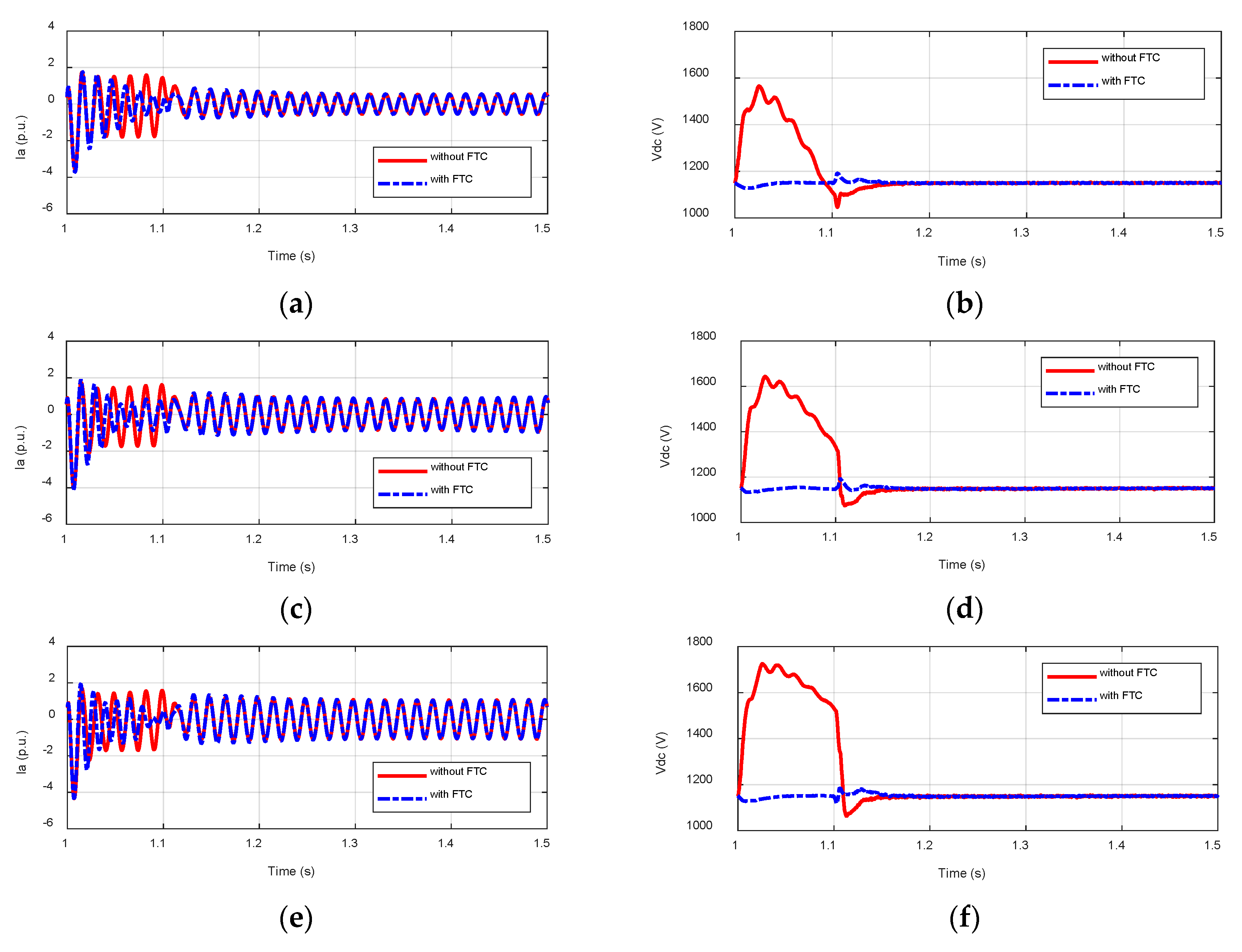
Simulation studies are carried out on a grid-connected WECS with DFIG wind farm in Simulink/ Simpower systems. The stator is directly connected to the power grid, while the rotor’s terminals are fed through a variable frequency via the converters in Figure 2. The simulation study of DC voltage overshoots is shown in Figure 3 and Table 1, where we can see the effectiveness of the proposed FTC scheme. The simulation study is presented with and without the proposed scheme in Figure 3, while wind speed variations result and hierarchical approach in Table 2 and Table 3, respectively. During the first phase under normal operating conditions, the resulting curve of variation of DC voltage is close to zero. However, after rated and high wind speeds, the fault occurs and the ratio increases suddenly. This sudden variation in the rate leads to fault recognition, shown in Figure 3 and Table 2.
The operation of the controller is implemented in Simulink and summarized in the proposed scheme’s flow chart depicted in Figure 1. The value of overshoots DC voltage is calculated by applying this method [25]. With the combination of PAC and MPPT, an FTC scheme is proposed and depicted in Figure 1 to enhance the fault-tolerant of the DFIG-based wind farm operating under balanced short-circuit and wind speed variations.
Overshoot % = (Vdc-max- Vdc-rated)/Vdc-rated

Discussion

The FTC is introduced to control the balanced short-circuit of the DFIG-based wind energy system. The MPPT and PAC are also applied during low, rated, and high wind speeds. In order to regulate the low and rated wind speeds, the MPPT controller is activated at the rotor side converter. The PAC controller is operated during the low, rated, and high wind speeds, as explained in Table 2 and Table 3 and Figure 3. During the low wind speed, PAC remains disabled and MPPT is activated. The FTC scheme is operated during low, rated, and high wind speeds and regulates the short-circuit DC voltage overshoots values following its rated rate. The DC voltage is depicted in Figure 3 and Table 1, which is observed to be harmful for the healthy operation of the system and synchronization with the grid. For the sake of comparison, Figure 3 shows the line current and DC voltage values at different wind speed ranges. The simulation results are depicted with and without applying the proposed schemes. When the balanced short-circuit is impassive and the DC overshoots voltage is reduced by FTC and suppressed to close to its rated value, which is maintained at less than 1.15 kV, the power coefficient value (Cp) is close to the maximum value (i.e., 0.45 p.u) for wind speeds under the rated value. The Cp decreases for high wind speeds to prevent damage. The TSR value is kept constant, while the Cp decreased during high wind speeds and MPPT is activated during low wind speeds. According to Equation (6), we must keep TSR constant at its optimal value by changing the rotor speed. We observe the Cp and TSR responses in Table 2. Table 2 demonstrates that Cp decreases with wind speed, and the pitch angle (β) increases with the rate of wind speed. Meanwhile, the reactive (Q) power is approximately constant owing to the robust reactive controller and is measured to be close to zero, whereas the value of Q is observed to be higher under high wind speeds and faults, which is depicted in Table 1.
In order to prevent the damage, cut-off, or shut-down of the power grid and DFIG system, the pitch angle is increased to obtain high wind speeds. Meanwhile, the DC voltage is close to its rated value (i.e., 1.150 kV) for all wind speed operations to keep the bus voltage of the wind farm close to the grid voltage for synchronization, as shown in Figure 3 and Table 2. Reactive power varies based on system operations, with the healthy and faulty results depicted in Table 2 and the simulation model parameters of DFIG presented in Appendix A (Table A1).

5. Conclusions

The FTC is activated when the short-circuit fault is detected. With the combination of PAC and MPPT, the FTC approach suppresses the DC overshoot and operates under the entire range of wind speeds. The hierarchical FTC approach depends on the PAC and MPPT controllers. The PAC scheme is applicable during the low, rated, and high wind speeds, while the MPPT scheme operates in low and rated wind speeds. The FTC scheme is immune under balanced short-circuit conditions on various wind speed ranges. The DFIG-based wind turbine system is simulated and the simulation results are presented in the figures and tables. Finally, a logical table is organized to demonstrate the FTC scheme for a smooth understanding of the whole process of the proposed scheme. The simulation results and measurements showed that the proposed controller deals better with such undesirable conditions and can compete as an alternative to other individual control structures of DFIG-based WECSs.

Author Contributions

M.S.N. contributed to the conceptualization, methodology, and original draft preparation; A.J.M. contributed to the methodology, software, and investigation; Y.W. and X.S. contributed to the review and editing; C.Z. and A.N.A. contributed to the formal analysis and review. All authors have read and agreed to the published version of the manuscript.

Funding

This research was funded by Faculty of Automation, Huaiyin Institute of Technology and under grant JAS2018020.

Acknowledgments

The listed authors are highly grateful to their Institutes for literature facilities.

Conflicts of Interest

The authors declare that they have no conflict of interest.

Appendix A

Table A1. Simulation Model Parameters of DFIG-Based Wind Farm.
ParametersValues
Rated power of each turbine1.5 MW
Line to line voltage (L–L)575 V (RMS)
Frequency60 Hz
Stator resistance (Rs)0.023 p.u
Rotor resistance (Rr)0.016 p.u
Magnetizing inductance (Lm)2.9 p.u
Friction factor0.013 p.u
DFIG inertia constant0.685 H(s)
Stator and rotor inductance0.18 p.u,
0.16 p.u
Rated mechanical power2.0090 MW
Rated apparent power2.2409 MVA
Rated power factor0.8987
Rated rotor speed22.5 rpm
No. of turbines6
Nominal DC bus voltage1150 V
Cut-in wind speed4 m/s
Rated wind speed15 m/s
Cut-out wind speed25 m/s
Number of rotor blades3
Grid side coupling inductor0.3 p.u
d-axis synchronous inductance, Ld1.22 mH
q-axis synchronous inductance, Lq2.33 mH
Optimal angle of stator current19.749
Frequency of grid-side PWM carrier2700 Hz
Frequency of the rotor-side PWM carrier1620 Hz

References

  1. Carunaiselvane, C.; Chelliah, T.R. Present trends and future prospects of asynchronous machines in renewable energy systems. Renew. Sustain. Energy Rev. 2017, 74, 1028–1041. [Google Scholar] [CrossRef]
  2. Nazir, M.S.; Mahdi, A.J.; Bilal, M.; Sohail, H.M.; Ali, N.; Iqbal, H.M. Environmental impact and pollution-related challenges of renewable wind energy paradigm—A review. Sci. Total Environ. 2019, 683, 436–444. [Google Scholar] [CrossRef] [PubMed]
  3. Sultana, W.R.; Sahoo, S.K.; Sukchai, S.; Yamuna, S.; Venkatesh, D. A review on state of art development of model predictive control for renewable energy applications. Renew. Sustain. Energy Rev. 2017, 76, 391–406. [Google Scholar] [CrossRef]
  4. Ahmed, W.; Ali, N.; Nazir, S.; Khan, A. Power quality improving based harmonical studies of a single phase step down bridge-cycloconverter. J. Electr. Syst. 2019, 15, 109–122. [Google Scholar]
  5. Taner, T. Economic analysis of a wind power plant: A case study for the Cappadocia region. J. Mech. Sci. Technol. 2018, 32, 1379–1389. [Google Scholar] [CrossRef]
  6. Taner, T.; Demirci, O.K. Energy and economic analysis of the wind turbine plant’s draft for the Aksaray city. Appl. Ecol. Environ. Sci. 2014, 2, 82–85. [Google Scholar] [CrossRef] [Green Version]
  7. Cho, S.; Gao, Z.; Moan, T. Model-based fault detection, fault isolation and fault-tolerant control of a blade pitch system in floating wind turbines. Renew. Energy 2018, 120, 306–321. [Google Scholar] [CrossRef]
  8. Kenan Döşoğlu, M.; Arsoy, A.B. Transient modeling and analysis of a DFIG based wind farm with supercapacitor energy storage. Int. J. Electr. Power Energy Syst. 2016, 78, 414–421. [Google Scholar] [CrossRef]
  9. Mu, W.; Wang, J.; Feng, W. Fault detection and fault-tolerant control of actuators and sensors in distributed parameter systems. J. Frankl. Inst. 2017, 354, 3341–3363. [Google Scholar] [CrossRef]
  10. Rousis, A.O.; Anaya-Lara, O. DC Voltage Control for Fault Management in HVDC System. Energy Procedia 2015, 80, 237–244. [Google Scholar] [CrossRef] [Green Version]
  11. Yang, B.; Jiang, L.; Wang, L.; Yao, W.; Wu, Q.H. Nonlinear maximum power point tracking control and modal analysis of DFIG based wind turbine. Int. J. Electr. Power Energy Syst. 2016, 74, 429–436. [Google Scholar] [CrossRef] [Green Version]
  12. Justo, J.J.; Bansal, R.C. Parallel R-L configuration crowbar with series R-L circuit protection for LVRT strategy of DFIG under transient-state. Electr. Power Syst. Res. 2018, 154, 299–310. [Google Scholar] [CrossRef]
  13. Li, W.; Chao, P.; Liang, X.; Sun, Y.; Qi, J.; Chang, X. Modeling of complete fault ride-through processes for DFIG-Based wind turbines. Renew. Energy 2018, 118, 1001–1014. [Google Scholar] [CrossRef]
  14. Nazir, M.S.; Wu, Q.H.; Li, M.; Luliang, Z. Lagrangian-Based Approach for Non-linear Dynamic Control of an Islanded Power System. Int. J. Comput. Sci. Inf. Secur. (IJCSIS) 2017, 15, 24–29. [Google Scholar]
  15. Liu, Y.; Wu, Q.H.; Zhou, X.X.; Jiang, L. Perturbation observer based multiloop control for the DFIG-WT in multimachine power system. IEEE Trans. Power Syst. 2014, 29, 2905–2915. [Google Scholar] [CrossRef]
  16. Nazir, M.S.; Abdalla, A.N. The robustness assessment of doubly fed induction generator-wind turbine during short circuit. Energy Environ. 2019. [Google Scholar] [CrossRef]
  17. Zamad, U.S.; Deshpande, A.P.; Patwardhan, S.C. LQG control with reconfigurable state estimator under sensor and actuator failures. IFAC Proc. Vol. 2007, 40, 147–152. [Google Scholar] [CrossRef]
  18. Göransson, L.; Johnsson, F. A comparison of variation management strategies for wind power integration in different electricity system contexts. Wind Energy 2018, 21, 837–854. [Google Scholar] [CrossRef]
  19. Smilden, E.; Bachynski, E.E.; Sørensen, A.J.; Amdahl, J. Wave disturbance rejection for monopile offshore wind turbines. Wind Energy 2019, 22, 89–108. [Google Scholar] [CrossRef] [Green Version]
  20. Nazir, M.S.; Wu, Q.; Li, M.; Zhang, L. Symmetrical Short Circuit Parameter Differences of Double Fed Induction Generator and Synchronous Generator based Wind Turbine. Indones. J. Electr. Eng. Comput. Sci. 2017, 6, 268–277. [Google Scholar] [CrossRef] [Green Version]
  21. Shahbazi, M.; Poure, P.; Saadate, S. Real-time power switch fault diagnosis and fault-tolerant operation in a DFIG-based wind energy system. Renew. Energy 2018, 116, 209–218. [Google Scholar] [CrossRef] [Green Version]
  22. Rahimi, A.; Kumar, K.D.; Alighanbari, H. Fault detection and isolation of control moment gyros for satellite attitude control subsystem. Mech. Syst. Signal Process. 2020, 135, 106419. [Google Scholar] [CrossRef]
  23. Wang, X.; Li, L.; Palazoglu, A.; El-Farra, N.H.; Shah, N. Optimization and control of offshore wind systems with energy storage. Energy Convers. Manag. 2018, 173, 426–437. [Google Scholar] [CrossRef]
  24. Wahab, O.A.; Bentahar, J.; Otrok, H.; Mourad, A. Optimal load distribution for the detection of VM-based DDoS attacks in the cloud. IEEE Trans. Serv. Comput. 2017, 1-1. [Google Scholar] [CrossRef]
  25. Lumbreras, C.; Guerrero, J.M.; Garcia, P.; Briz, F.; Reigosa, D.D. Control of a small wind turbine in the high wind speed region. IEEE Trans. Power Electron. 2015, 31, 6980–6991. [Google Scholar] [CrossRef]
  26. Shahzad Nazir, M.; Wu, Q.; Li, M. Symmetrical short-circuit parameters comparison of DFIG–WT. Int. J. Electr. Comput. Eng. Syst. 2017, 8, 77–83. [Google Scholar] [CrossRef] [Green Version]
  27. Kazemi Golkhandan, R.; Aghaebrahimi, M.R.; Farshad, M. Control strategies for enhancing frequency stability by DFIGs in a power system with high percentage of wind power penetration. Appl. Sci. 2017, 7, 1140. [Google Scholar] [CrossRef] [Green Version]
  28. Naderi, S.B.; Davari, P.; Zhou, D.; Negnevitsky, M.; Blaabjerg, F. A Review on Fault Current Limiting Devices to Enhance the Fault Ride-Through Capability of the Doubly-Fed Induction Generator Based Wind Turbine. Appl. Sci. 2018, 8, 2059. [Google Scholar] [CrossRef] [Green Version]
  29. Zhang, Y.; Jiang, J. Bibliographical review on reconfigurable fault-tolerant control systems. Annu. Rev. Control 2008, 32, 229–252. [Google Scholar] [CrossRef]
  30. Kadhem, A.A.; Wahab, N.I.A.; Aris, I.; Jasni, J.; Abdalla, A.N. Advanced wind speed prediction model based on a combination of weibull distribution and an artificial neural network. Energies 2017, 10, 1744. [Google Scholar] [CrossRef] [Green Version]
  31. Mahdi, A.; Tang, W.; Wu, Q. Novel perturbation and observation algorithms for variable-speed wind turbine generator systems. In Proceedings of the 2012 IEEE Power and Energy Society General Meeting, San Diego, CA, USA, 22–26 July 2012. [Google Scholar]
  32. Mahdi, A.; Tang, W.; Wu, Q. Derivation of a complete transfer function for a wind turbine generator system by experiments. In Proceedings of the 2011 IEEE Power Engineering and Automation Conference, Wuhan, China, 8–9 September 2011. [Google Scholar]
  33. Taner, T. Optimisation processes of energy efficiency for a drying plant: A case of study for Turkey. Appl. Therm. Eng. 2015, 80, 247–260. [Google Scholar] [CrossRef]
  34. Taner, T. Energy and exergy analyze of PEM fuel cell: A case study of modeling and simulations. Energy 2018, 143, 284–294. [Google Scholar] [CrossRef]
  35. Ellabban, O.; Abu-Rub, H.; Blaabjerg, F. Renewable energy resources: Current status, future prospects and their enabling technology. Renew. Sustain. Energy Rev. 2014, 39, 748–764. [Google Scholar] [CrossRef]
  36. Olivier-Maget, N.; Hétreux, G.; Le Lann, J.M.; Le Lann, M.V. Fault detection and diagnosis based on a hybrid dynamic simulator. IFAC Proc. Vol. 2009, 42, 223–228. [Google Scholar] [CrossRef]
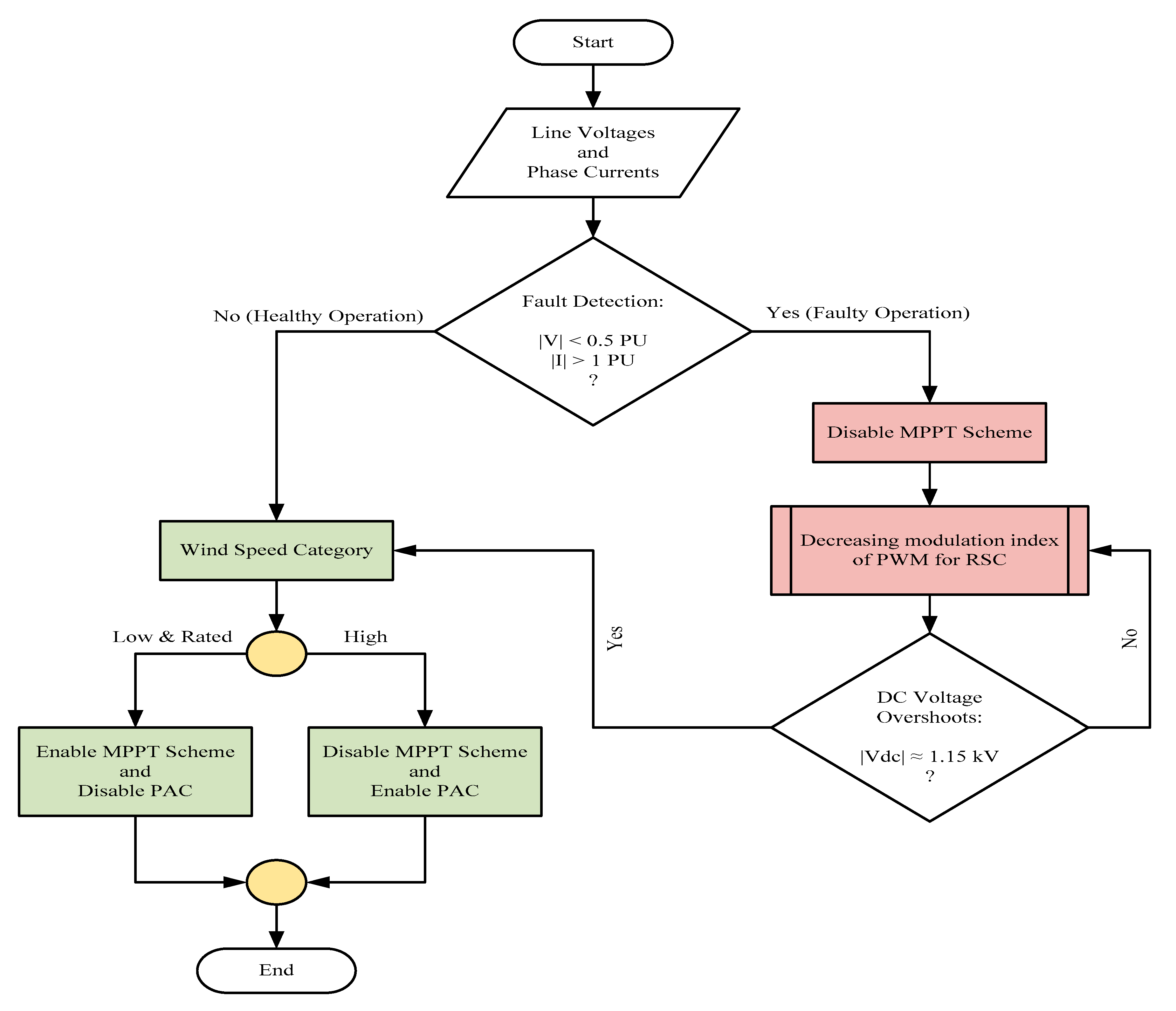
Figure 1. Proposed scheme for the fault tolerant control (FTC) controller. PAC, pitch angle control; MPPT, maximum power point tracking; RSC, rotor side converter.
Applsci 10 00924 g001
Figure 2. The block diagram of the doubly-fed induction generator (DFIG)-based wind power system.
Applsci 10 00924 g002
Figure 3. Line current and DC voltage (with/without FTC) for comparison results during low wind speed. (a) Line current at low wind speed; (b) DC voltage at low wind speed; (c) Line current at rated wind speed; (d) DC voltage at rated wind speed; (e) Line current at high wind speed; (f) DC voltage at high wind speed.
Applsci 10 00924 g003
Table 1. DC voltage overshoot under short-circuit and various wind speed ranges.
Wind Speed (Category)Max. Overshoot of DC (VDC) Voltage (%)Max. Overshoot of Active (P) Power (%)Max. Overshoot of Reactive (Q) Power (%)
Low37%16%107%
Normal43%40%928%
High48%59%1043%
Table 2. Numerical results for normal operation under wind speed variations. TSR, tip speed ration.
Wind Speed (Category)TSR (-)Cp (-)Pitch Angle (β)DC Voltage (kV)Active Power (P) (MW)Reactive Power (Q) (MVAR)
Low12.730.43701.1505.404−0.35
Normal7.310.2778.61.1509.037−0.39
High5.340.049231.15310.869−0.23
Table 3. Hierarchical operation table of the implemented fault tolerant control (FTC) scheme. PAC, pitch angle control; MPPT, maximum power point tracking.
Wind Speed CategoryOperation ModeControl States for PWM of Rotor Side Converter (RSC)
MPPTPACHFTC
LowHealthy100
Faulty011
NormalHealthy110
Faulty011
HighHealthy010
Faulty011