Article

A Novel Dense Full-Field Displacement Monitoring Method Based on Image Sequences and Optical Flow Algorithm

1
School of Civil Engineering, Chongqing Jiaotong University, Chongqing 400074, China
2
College of Civil and Transportation Engineering, Shenzhen University, Shenzhen 518061, China
*
Author to whom correspondence should be addressed.
Appl. Sci. 2020, 10(6), 2118; https://doi.org/10.3390/app10062118
Submission received: 17 February 2020 / Revised: 14 March 2020 / Accepted: 15 March 2020 / Published: 20 March 2020
(This article belongs to the Special Issue Novel Approaches for Structural Health Monitoring)

Abstract

:

Featured Application

This method can be applied to health monitoring of large-scale bridge structures, and the deformation of bridge structures can be monitored regularly and nondestructively using camera as a noncontact sensor. In order to improve measurement accuracy, a uniaxial automatic cruise acquisition device was designed to obtain the deformation of bridge elevation. The measurement points using the proposed method are denser than those of the traditional sensor measurement method. It can also detect abnormal deformation caused by the damage, and it is more efficient and easier to use.

Abstract

This paper aims to achieve a large bridge structural health monitoring (SHM) efficiently, economically, credibly, and holographically through noncontact remote sensing (NRS). For these purposes, the author proposes a NRS method for collecting the holographic geometric deformation of test bridge, using static image sequences. Specifically, a uniaxial automatic cruise acquisition device was designed to collect static images on bridge elevation under different damage conditions. Considering the strong spatiotemporal correlations of the sequence data, the relationships between six fixed fields of view were identified through the SIFT algorithm. On this basis, the deformation of the bridge structure was obtained by tracking a virtual target using the optical flow algorithm. Finally, the global holographic deformation of the test bridge was derived. The research results show that: The output data of our NRS method are basically consistent with the finite-element prediction (maximum error: 11.11%) and dial gauge measurement (maximum error: 12.12%); the NRS method is highly sensitive to the actual deformation of the bridge structure under different damage conditions, and can capture the deformation in a continuous and accurate manner. The research findings lay a solid basis for structure state interpretation and intelligent damage identification.

1. Introduction

With the elapse of time, it is inevitable for a bridge to face structural degradation under the long-term effects of natural factors (e.g. climate and environment). In extreme cases, the bridge structure will suffer from catastrophic damages with the continuous increase in traffic volume and heavy vehicles, due to the booming economy [1]. The traditional approach of structural management, which is mainly manual periodic inspection, can no longer satisfy the demand of modern transport facilities. The traditional approach is inefficient, uncertain, and highly subjective, lacking in scientific or quantitative bases [2,3,4,5].
Structural health monitoring (SHM) aims to monitor, analyze, and identify all kinds of loads and structural responses during the service life of the target structure, to realize the evaluation of its structural performance and safety status, and provide support for the proprietor in structural management and making maintenance decisions [6,7,8]. In order to achieve this goal, a new sensor technology must be developed in combination with interdisciplinary theories and methods to provide advanced monitoring methods and reliable data sources for SHM [9,10,11]. Displacement is an important index of structural state and performance evaluations [7]. The static and dynamic characteristics of a structure, such as bearing capacity [12], deflection [13], deformation [14], load distribution [15], load input [16], influence line [17], influence surface [18], and modal parameters [19,20], can be calculated by structural displacement, to convert them further into physical indicators of response for structural safety assessment.
Since the 1990s, SHM systems have been set up on important large-span bridges across the globe. The main functions are to monitor the state and behavior of the bridge structure, while tracking and recording environmental conditions. On the upside, these systems have high local accuracy, run on an intelligent system, and support long-term continuous observation. On the downside, these systems are too costly to construct, the sensors cannot be calibrated periodically, and the layout of monitoring points is limited by a local terrain and the structure type. The geometric deformation of the bridge structure can only be collected by a few discrete monitoring points, making it difficult to characterize the local or global holographic geometry of bridge safety [21,22,23,24,25].
With the continuous development of machine vision technology and image acquisition equipment, structural displacement monitoring methods based on computer vision continues to emerge and have been verified in practical engineering applications [26,27,28,29,30]. Given its long-distance, noncontact, high-precision, time-saving, labor-saving, multi-point detection, and many other advantages, as well as increasing attention has been received from scientific researchers and engineers [31]. This method is mainly used to track the target of the measured structure video, which is captured by the camera, to obtain the moving track of the measuring point in the image, and then determine the displacement information of the structure through the set relationship between the image and the real world. The camera is mounted on a fixed point which is far from the structure to be tested, eliminating the requirement to install a fixed support point on the structure for the contact displacement detection method. In addition, low-cost multi-point measurement it is easy to achieve because the camera field of view can cover multiple measurement areas of the structure. Structural displacement monitoring based on computer vision has been applied in many tasks of bridge health monitoring, such as bridge deflection measurement [32], bridge alignment [33], bearing capacity evaluation [34], finite element model calibration [35], modal analysis [36], damage identification [18], cable force detection [29], and dynamic weighing assistance [12]. The images can also improve the accuracy of the estimation part through several means, such as deblurring, denoising and image enhancement, and even satellite images are gradually applied in structural monitoring [37,38].
Although the application of machine vision technology in structural displacement monitoring has many advantages, there are still some problems to be solved. In the recent research, part of it is aimed at small-scale structure, which can capture all structure displacements with a camera’s field of view. However, for large-scale structure monitoring, to achieve sufficient accuracy, only the structural displacement for a specific area of the structure can be obtained, ignoring the overall deformation state of the structure from the macro view as a whole. Meanwhile, as a kind of holographic data, machine vision can obtain the displacement information of every pixel of an image in theory, but is mainly focused on obtaining the displacement information of key points in practice.

2. Purpose and Concept

On this basis, this paper proposes a method of obtaining the displacement information of an whole bridge structure from different views. According to the field of view of a camera, the bridge structure is divided into several areas, and image data are collected under different working conditions to form the image database of the bridge facade under the time–space sequence. The entire field displacement information of the bridge is obtained by establishing the connection between the time and space series. For this purpose, noncontact remote sensing (NRS) is designed to obtain the time–space sequence image data of the test bridge under different test conditions.
In order to obtain the full field displacement deformation of the whole structure, it is no longer used to track the artificial marked and corner points as the target points, but to track the displacement information by extracting every pixel of the lower edge contour line of the main beam as the virtual marked points. Modelling correction and damage identification is more conducive than measuring of finite points. Abundant data can be accumulated to provide more details data for machine learning and life-cycle maintenance.
The paper is organized as follows. Section 3 covers the theoretical background of the intelligent NRS system and the layout of lab. Section 4 proposes the algorithm to connect the fields of view and track the deformation, presents the analysis with the theoretical model, and discusses the validation of the proposed sensor and algorithms in full-field noncontact displacement and vibration measurement. The results are summarized in Section 5.

3. Test Overview

3.1. Intelligent NRS System

This paper designs an intelligent NRS system for the holographic monitoring of bridge structure based on virtual pixel sensors and several cutting-edge techniques (i.e., modern panoramic vision sensing, pattern recognition, and computer technology). As shown in Figure 1a, this intelligent NRS system mainly consists of an active image acquisition device, an automatic cruise remote control platform, an environmental monitoring unit, a signal transmission unit, and a data storage and analysis unit.
To monitor the holographic geometry of the bridge structure, the automatic cruise parameters (preset position, watch position, cruise time, and sampling time) are configured by a computer to remotely control the active image acquisition device and the environmental monitoring unit. In this way, the dynamic and static images of the bridge structure can be captured in the current field of view. Figure 1b is a photo of the intelligent NRS system for our load tests on the reduced-scale model of a super long span self-anchored suspension bridge. The workflow of the intelligent NRS system is explained in Figure 2.

3.2. Object and data Collection

According to the previous research of our research team [39,40,41], a 1:30 model was constructed for Taohuayu Yellow River Bridge. A total of 52 C30 concrete deck slabs (1.16 × 0.45 × 0.2 m) were prepared and laid on the steel box girder to simulate vehicles on the bridge and serve as the counterweight.
The main cable is composed of 37 steel wire ropes with a diameter of 2mm, an elastic modulus of 195 GPa and a ftk of 1860 MPa. The suspender is composed of steel wire ropes with a diameter of 4mm, an elastic modulus of 195 GPa, and a ftk of 1860 MPa. The main tower adopts a thin-walled box made of steel plate with a thickness of 6 mm and Q345D material.
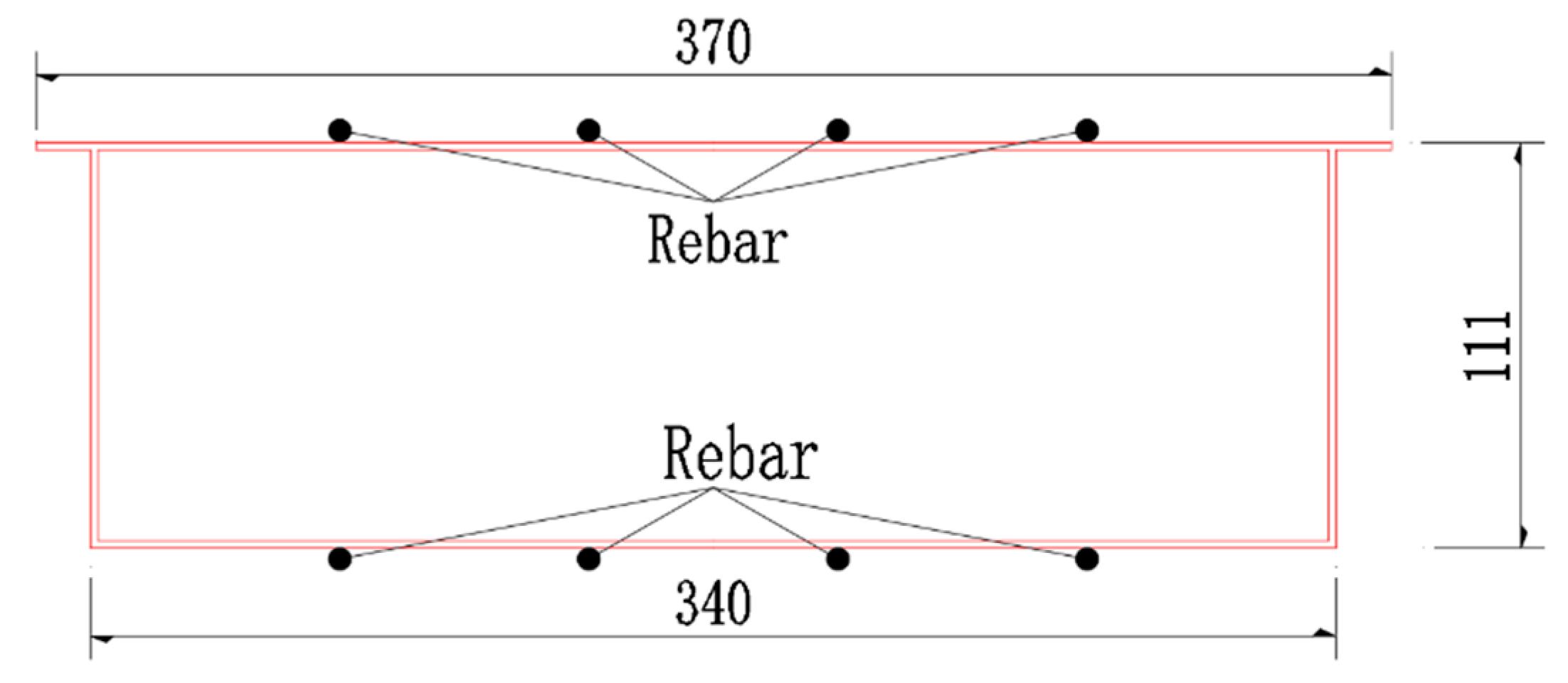
The standard section of the main beam is shown in Figure 3 in which the top, web, and bottom plates are made of 2 mm thick steel plates. Owing to the strong axial force of the main beam, considering the stability of the box girder, the top and bottom of the girder have four solid steel stiffeners (Φ 6 rebar), which are connected with the top and bottom plates of the box girder by spot welding.
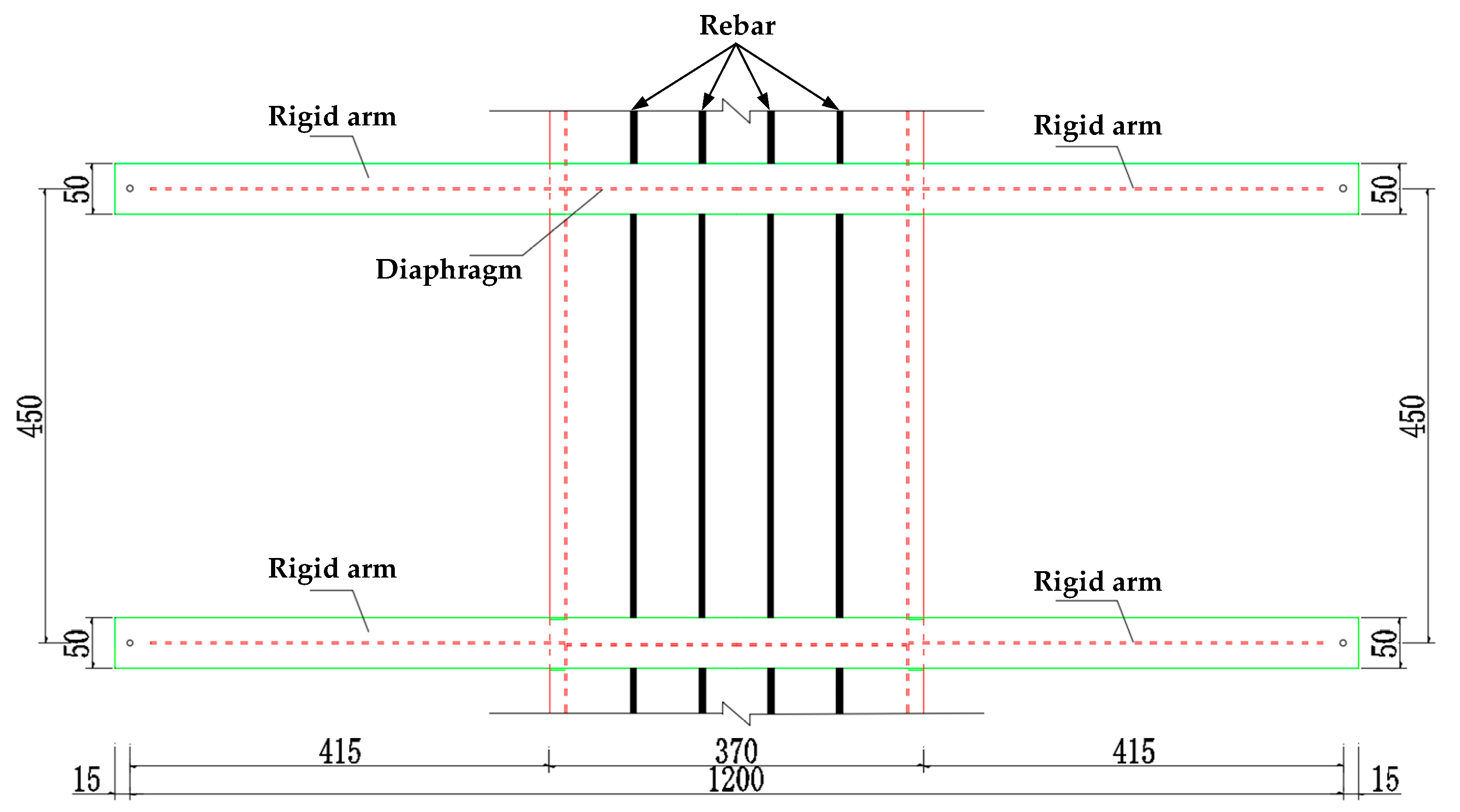
In order to fully simulate the geometric similarity between the suspender and the main beam, the rigid arm is extended from both sides of the main beam at the lifting point, and the anchor plate is set on the rigid arm so that the suspender can be connected with the stiffener. Steel is selected for the rigid arm. To ensure the local stability of the main beam, one diaphragm is set every 450 mm (i.e., the section of the lifting point) of the main beam model, and the diaphragm and the main beam can be connected with the steel box girder by welding. The diaphragm plate is made of Q345D steel with a thickness of 2mm. As shown in Figure 4 and Figure 5, respectively.
The rigid arm has 5 cm wide and 5 mm thick steel plates, which are arranged through the cross-section of the main beam. The rigid arm is connected to the top plate of the steel box girder through welding; the stiffener adopts a 3 mm thick steel plate, which is connected to the main beam and the rigid arm through welding. The main beam is processed in the factory. The total length of the main beam is 24.2 m, which is divided into 24 sections: 1.3 + 6 × 3.6 + 1.3 m. Figure 6 is a photo of the reduced-scale model.
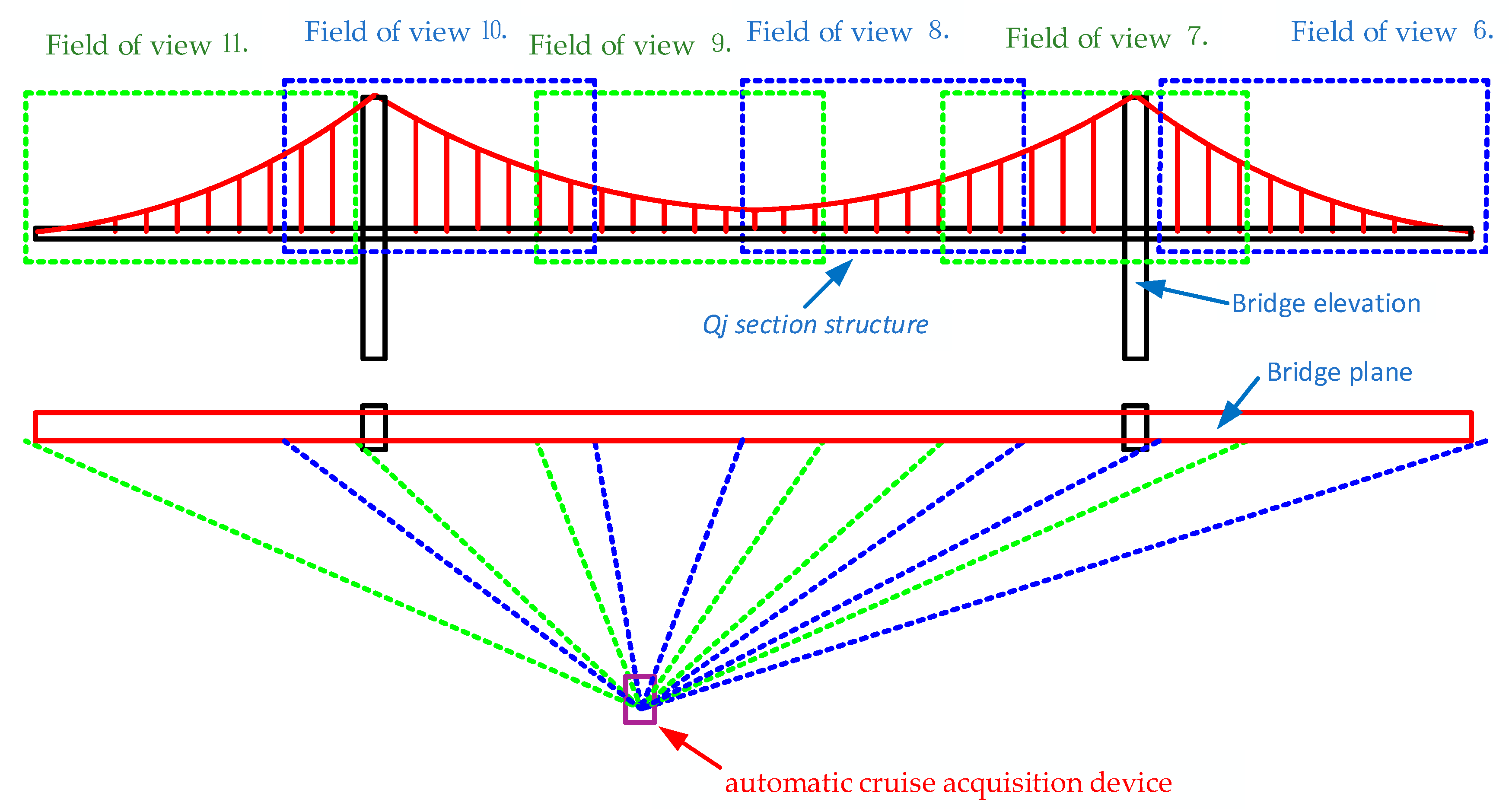
The intelligent NRS system was set up 5m away from the bridge façade. Then, a computer-controlled camera rotated at fixed angles to collect the images of specific sections of the bridge from fixed positions. The layout of the lab and the principle of image collection are shown in Figure 7 and Figure 8, respectively.
To verify the feasibility of the image collection method, 11 dial gauges were arranged along the axis of the bridge to capture the shape change while the camera took photos of the bridge, DH5902N is adopted for data acquisition equipment. The arrangement of the dial gauges is displayed in Figure 9 below.

3.3. Test Contents

The structural deformation data of the bridge were collected under two scenarios to obtain the deformation of the test bridge with the intelligent NRS system and provide more samples for the tracking algorithm. In the first scenario, the bridge had no damage, the test load (50kg) was placed on the middle of the test bridge, and image data on the structural change were collected. In the second scenario, different suspension cables were damaged to simulate varied degrees of bridge damages at different positions, the test load (50 kg) was placed on the same place as the first scenario, and image data on the structural change were collected. Table 1 lists the positions and numbers of damaged suspension cables. The serial numbers of suspension cables are provided in Figure 10.

3.4. Finite Element Model

The finite element model is established by Midas Civil [39,40,41]. The ratio of side to span of the self-anchored suspension test bridge is 1:2.5, and the ratio of rise to span is 1:5.8. The structure is a spatial bar model. The main tower, main beam and cross beam are all simulated by a beam element. The main beam is simulated by fishbone type, and the main cable and suspender are simulated by cable element. The whole bridge model consists of 388 elements and 293 nodes. A rigid connection is adopted between the end of main cable and main beam. The main cable and the suspender, the main cable and tower, and the suspender and the main beam share the same nodes, and no connection is set, as shown in Figure 11. Main material parameters are shown in Table 2.
Main modeling steps: (1) According to the overall design of the suspension bridge, select the corresponding material and section characteristics of each component to initially generate the linearity of the main cable and the initial internal force of the main cable. (2) establish a complete bridge calculation model. (3) define the update node group and vertical analysis function to accurately calculate the structure, and obtain the internal force data of the balance unit node to obtain the initial balance of the suspension bridge state. (4) adjust the cable force of the suspender to a reasonable completion state until the bending moment of the main beam meets the design requirements. The distribution of the suspender force is shown in Figure 12.

4. Design of Multipoint Displacement Monitoring Algorithm for Bridge Structure

This experiment simulates two problems faced by the noncontact measurement of a large-scale bridge structure. One is the inability to obtain the monitoring image data of the whole bridge through one field of view, which obviously reduces the accuracy of the captured structural changes. Another is the accurate transformation of the displacement of the concerned part in the time series image data. In view of these two problems, this paper proposes a method of acquiring the structural deformation of a large-scale bridge structures by using a uniaxial automatic cruise acquisition device to collect data in different fields of view and establish the relationship between data images in time and space.

4.1. Location and Extraction Method of Bridge Structure Contour

Many studies on camera calibration and perspective transformation have been conducted, and the corresponding theory and application are relatively mature. In this paper, the calibration method of Zhang Zhengyou [42,43] and the perspective transformation method of Jack Mezirow [44] were used directly and are not explained in detail.
The images collected by the intelligent NRS system contain the time sequences in a fixed field of view. Hence, the grayscales and contours were extracted from six images by MATLAB edge function [45], as shown in Figure 13.
The Canny edge detector was adopted for the extraction process. This operator finds the edge points in four steps: smoothing the images with a Gaussian filter, computing the gradient amplitude and direction through finite-difference computing with first-order derivative, applying non-maximum suppression to the gradient amplitude, and using a double threshold to detect and connect the edges.
The Canny edge detector could effectively extract the contours of the bridge structure from the static images collected by the intelligent NRS system. The extracted contours were further processed by a graphics processing software to decontextualize the contours of the useless parts, leaving only the lower edge contour of the deck slabs to reflect the variation in structural shape.
Since the fields of view in the six images are fixed, the contours of the bridge structure were located by the following method. The six images containing the initial boundary of the bridge structure were taken as the original images. The coordinates of each pixel in the boundary were extracted from the six images. Based on these coordinates, each pixel was marked in the original images, revealing the position of the initial boundary. The manual marking helps to suppress the noises in the images. In the subsequent deep learning, the contours could be automatically tracked based on the marked pixels, revealing the change features of the bridge structure. The specific flow of denoising and marking is shown in Figure 14.

4.2. The Method of Establishing the Space-Time Relationship of Image Sequence Data

4.2.1. Dataset Construction Based on Spatiotemporal Static Image Sequences

To realize the holographic monitoring of the bridge structure with the uniaxial automatic cruise acquisition device, the key lies in setting up the global and local holographic data based on the dynamic and static image sequences, which were captured at different times from multiple angles and fields of view.
The data in the static image sequences have four main features: Multi-time, multi-field of view, multi-angle, and a strong correlation between time and space. First, the holographic data collected in different fields of view differed in time history. Second, based on technical and economic considerations, the local details of the bridge structure were monitored with a few devices in different fields of view, yielding the local holographic data in each field of view. Third, the data were collected by the automatic cruise device at different watch positions, and the resulting angle difference should be adaptively equalized in the data processing. Fourth, the spatiotemporal features of the original data were determined by the random impact of the entire bridge at the current moment or period, and the structural response in local field of view reflects the overall state of the whole structure to different degrees.
Meanwhile, the cameras responsible for six fields of view (overlap ratio: 20%–30%) each cruised seven times under each damage condition. For the stability of the collected data, seven sets of images were collected on the load in the same field of view under each damage condition.
During data acquisition, the time and the space pointers were constructed based on the features of the intelligent NRS system and the image sequences. The former (time dimension) indicates the current damage condition and the field of view, and the latter (spatial dimension) reflects the position of the current local area relative to the global structure. The spatiotemporal features of the data sequences in the static images are presented in Figure 15 below.
In view of the data features, temporal information and spatial information were added into the dataset as labels before deep learning. The temporal information indicates the variation in damage condition and the order of images in the same field of view, and the spatial information reflects the correlation between a local structure with the global structure in a field of view. On this basis, the temporal, spatial and angular data were constructed for the original data, and then integrated with the environmental data (i.e. temperature, humidity, and illumination). The labels can be expressed as:
labels{i,j}(m,n) = np.arange(Time_lable,Space_lable,Angle_lable,Env._lable)
where i is the serial number of damage conditions of the test bridge (i = 1–6); j is the label position under different damage conditions (1 for Time, 2 for Space, 3 for Angle, …); m is the invocation parameter of the data on labels Time, Space, Angle and Environment in a local field of view; n is the serial number of measurements under the same damage condition, i.e. the time history of the same damage condition in the same field of view; Time_label, Space_label, Angle_label and Env._label are the matrices of labels Time, Space, Angle, and Environment, respectively.
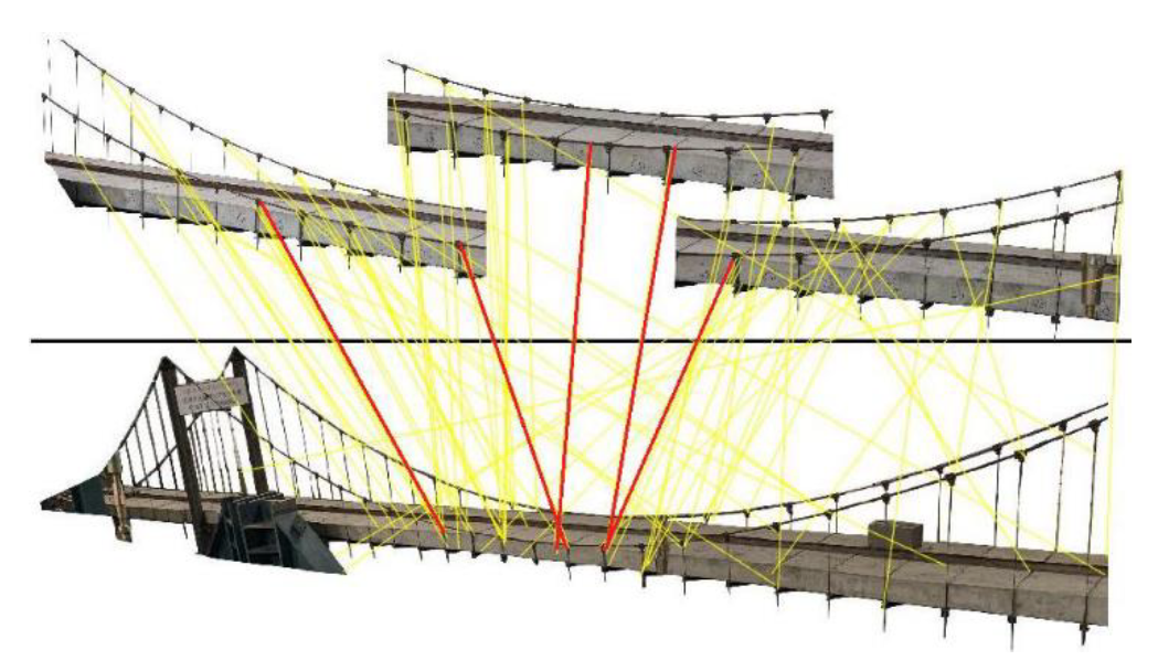
After tagging the photos in the spatiotemporal sequence through the above steps, the photos are connected in the spatial sequence by using the overlapping part between field of view n and field of view n + 1 (n = 1–5). The rich feature points and the SIFT feature points of the test bridge structure must be matched [46,47] in the image data. As shown in Figure 16, the yellow line is the corresponding relationship between the local feature points of the structure in different fields of view and the overall feature points of the structure. The matching results of the feature points of the structure itself and the feature points of the structure SIFT are good. The red line in Figure 11 is the most similar line between the field of view n of the test bridge and the feature points of the whole bridge. The line after matching according to the similarity in the calculation process of the algorithm is used as the constraint condition of edge registration theory and the basis of the displacement measurement information (the red line is the need of explanation, but the actual line should be the yellow line). However, many mismatches in the calculation of the algorithm remain, such as the connection of several characteristic points on the bridge tower and the reaction frame. Therefore, the greedy algorithm is used in this study to re-express the matching set of feature points, and the matching similarity rate is calculated by traversing the proximal and the sub proximal points in the process of filtering. The error matching points in the feature matching set are eliminated by optimizing the selection of each calculation in the process of traversing.
Euclidean Distance: d i , j = i = 1 n ( S i S j ) 2
HMF: O b j ( x ) = i = 1 m j = 1 n | H i j ( x , y , z ) H i j ( x , y , z ) H i j ( x , y , z ) | ( S i S j ) 2
According to the Euclidean distance calculation, the correlation degree between the spatial feature points of the test bridge structure is used for the optimal matching of the feature point set, where di,j is the Euclidean distance between feature points, Si and Sj are the spatial feature point set. HMF is the control equation of superposition analysis of displacement calculation in the space–time domain, where m and n are the serial numbers of spatial feature points; x, y, and z are the spatial coordinates of feature points; H i j ( x , y , z ) is the structural holographic morphological response measurement of a certain time in a certain field of view; and H i j ( x , y , z ) is the reference state of the structural holographic morphological response measurement.

4.2.2. Target Tracking and Displacement Calculation

In the previous research, the static image is used to extract the contour of the bridge structure at different times and under different load-damage conditions, and carry out stacking to obtain the deformation of the bridge structure. Given that this method has many manual interventions, the optical flow optical flow algorithm which is widely used in computer vision, was adopted for target tracking and displacement calculation in the static image sequence data collection [48,49].
The algorithm using optical flow must satisfy two hypotheses: (1) constant brightness: The brightness of the same point does not change with time; (2) small motion: The position will not change drastically with over time, such as finding the derivative of grayscale relative to the position. In our research, both hypotheses were satisfied by the data collected by the NRS. The brightness of each point in the collected images remained constant because of the small data interval of the seven time sequences; the small motion was also fulfilled, and the bridge structure had a limited deformation for the monitoring object.
Basic constraint equation. Consider the light intensity of a pixel f(x, y, t) on the first picture (where t represents its time dimension). It moves the distance (dx, dy) to the next picture because it is the same pixel point, and according to the first assumption above, the light intensity of the pixel before and after the motion is constant.
f ( x , y , t ) = f ( x + d x , y + d y , t + d t )
The Taylor expansion on the right end of Formula (1) is as follows:
f ( x + d x , y + d y , t + d t ) = f ( x , y , t ) + f x d x + f y d y + f t d t + ε
where ε represents the second order infinitesimal term, which could be ignored; then (2) is substituted into (1) and divided by dt:
f x d x d t + f y d y d t + f t = 0
Let f x = f x , f y = f y , f t = f t represent the partial derivatives of the gray level of the pixels in the image along the x, y, and t directions. Summing up,
f x u + f y v + f t = 0
where, f x , f y , and f t can be obtained from the image data, and (u, v) is the optical flow vector that must be solved.
At this time, there is only one constraint equation but two unknowns. In this case, the exact values of u and v cannot be obtained. Constraints need to be introduced from another perspective. The introduction of constraints from different angles leads to different methods of optical flow field calculation. According to the difference between the theoretical basis and the mathematical method, they are divided into four kinds: Gradient-based method, matching-based method, energy-based method, phase-based method, and neurodynamic method. In addition to distinguishing the optical flow method according to different principles, the optical flow method can also be divided into dense optical flow and sparse optical flow according to the density of a two-dimensional vector in the optical flow field.
Dense optical flow is a kind of image registration method that matches the image or a specific area point by point. It calculates the offset of all the points on the image to form a dense optical flow field. Through this dense optical flow field, pixel level image registration can be performed. In contrast to dense optical flow, sparse optical flow does not calculate every pixel of the image point by point. It usually needs to specify a group of points for tracking, which is better to have some obvious characteristics, such as the Harris corner, for a relatively stable and reliable tracking. The computation cost of sparse tracking is much less than that of dense tracking.
Since the collected image has less data than the video and does not pursue timeliness and according to the object extraction method described in Section 3.1, the displacement of all points on the image need not be calculated, but the offset of each pixel on the extracted contour line for pixel level image registration must be calculated. Thus, the Horn-Schunck algorithm [50] was selected. The Horn-Schunck algorithm belongs to the dense optical flow with the best accuracy. The objective function of the Horn-Schunck algorithm is as follows:
min u , v E ( u , v ) = [ ( T ( x , y ) f ( x + u , y + v ) ) 2 + λ · ( u x 2 + u y 2 + v x 2 + v y 2 ) ] d x d y
In order to facilitate the calculation, the approximation method in the sparse optical flow is used to approximate the data items linearly to obtain a new objective function:
min u , v E ( u , v ) = [ ( f x u + f y v + f t ) 2 + λ · ( u x 2 + u y 2 + v x 2 + v y 2 ) ] d x d y
The definite integral of the above formula can be rewritten into discrete form. Then, the corresponding Jacobian iterative formula can be obtained by the super relaxation iterative method (SOR):
u = u ¯ f x f x u ¯ + f y v ¯ + f t a + f x 2 + f y 2
v = v ¯ f y f x u ¯ + f y v ¯ + f t a + f x 2 + f y 2
According to Equations (11), (14), and (15), optical flow vectors t i to t i + 1 can be calculated, and all time u i and v i can be summed to calculate the displacement of the pixel point.

5. Extraction Deformation and Discussion

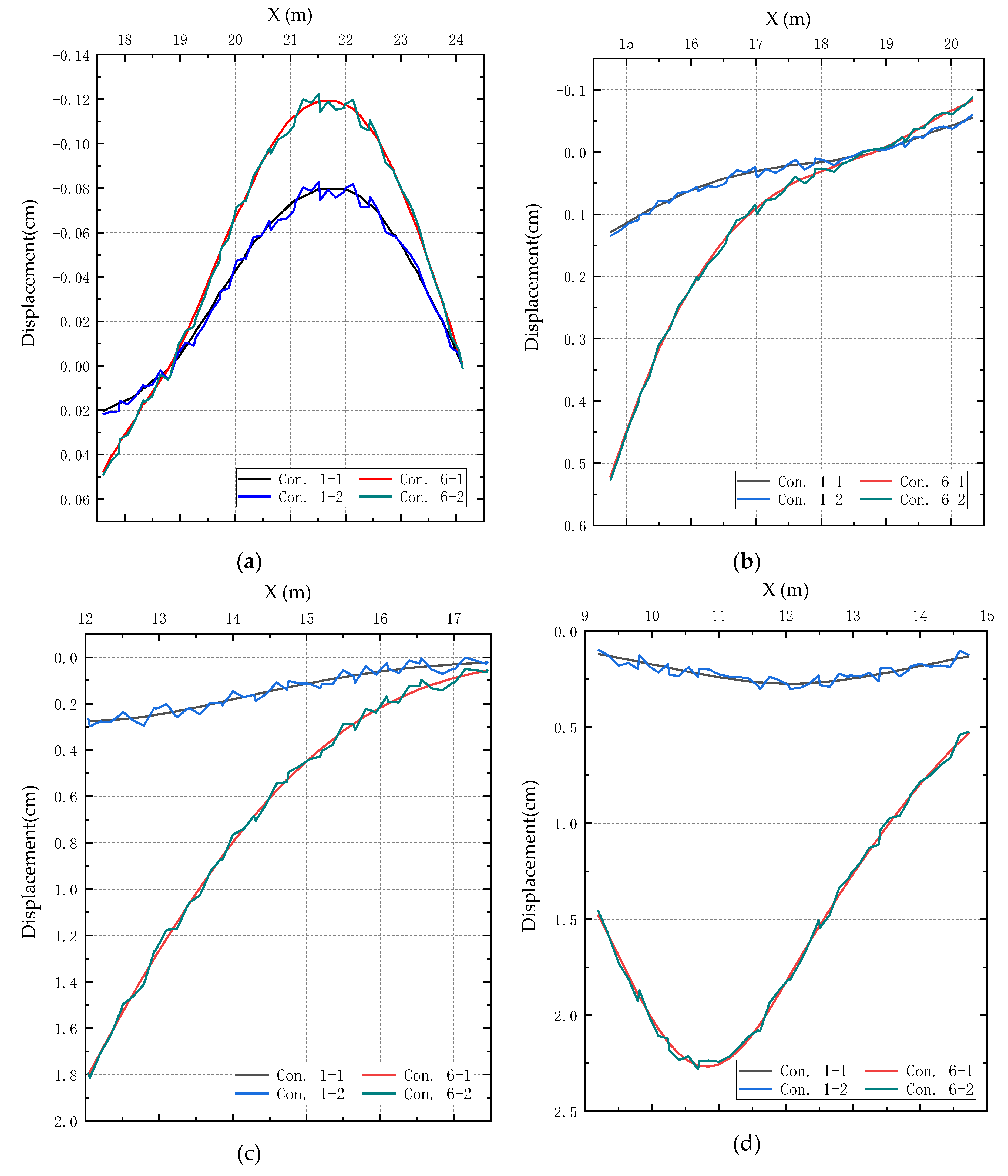
The MATLAB edge function and the Canny edge detector were adopted to extract the grayscale and contour from each image in the static image sequences of the test bridge under different damage conditions. Based on the extracted feature, the contours were marked on the original images. Then, the marked images and the subsequently taken images were compiled into a dataset. After that, the SIFT algorithm was applied to establish the spatial relationship between the fields of view, and the optical flow algorithm was used to track the displacement information of the lower edge contour of the main beam, based on the images collected by the NRS method (proposed in this paper). Since there are too many working conditions and the generated data to show well, the bridge tower consolidation point was used as the reference point to compare the nondestructive working condition (con. 1) obtained by the two methods and the working condition (con. 6) that shows the most obvious damage and deformation. In the figure, "- 1" represents the data obtained from finite element calculation, and "- 2" represents the data obtained from the method proposed in this paper, as shown in Figure 17.
As shown in Figure 17, the deformation curves of our method are less smooth than those of the finite-element method. There are two possible reasons for the lack of smoothness. Firstly, the lower edge of the deck slabs marked in the original images, which was considered as the contour of the bridge structure, is not smooth and even discrete in some places. Secondly, the positions of the marked pixels changed greatly after the bridge deformed, and were not captured accurately through deep learning.
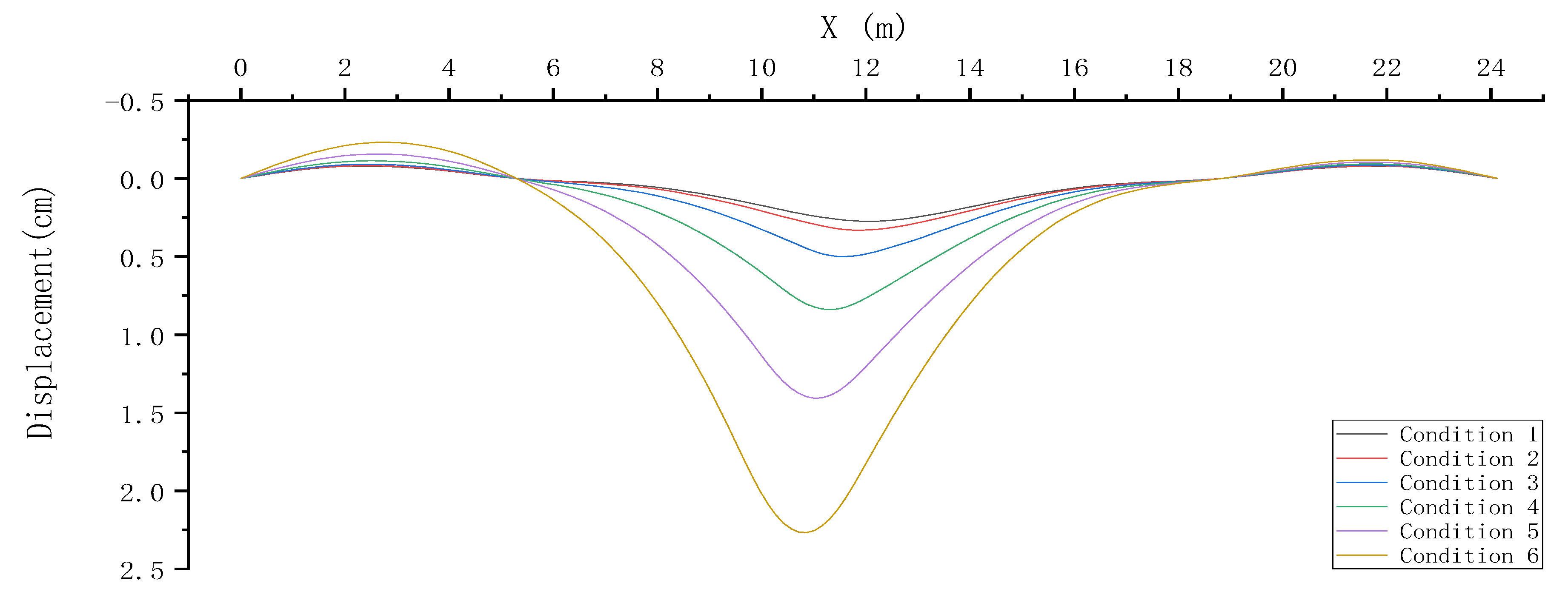
The first problem was solved through the contour stacking analysis in structural deformation monitoring, which is a method previously developed by our research team. This method treats the initial contours as known white noises of the system, and subtracts them from the contours acquired under different damage conditions. The second problem calls for improvement of the capture algorithm. Here, the improvement is realized through manual intervention. In this way, the bridge deformation data in the six fields of view were integrated into the global holographic deformation of the test bridge (Figure 18).
The deformation map of the test bridge based on the 11 dial gauges is not presented here. Even if fitted, the data collected by these gauges were discrete to demonstrate the global deformation features of the test bridge. Moreover, the initial state of the test bridge was not measured at the completion. Consequently, the actual stress state of the bridge structure at that moment is impossible to determine. However, the relative deformation of the test bridge in the monitoring period can be obtained from Figure 18. The obtained results were compared with the relative deformation recorded by the dial gauges to verify the accuracy of our method.
Out of the many damage conditions, the greatest difference lies between damage conditions 1 (no damage) and damage condition 6 (suspension cables 20–24 are damaged). Thus, these two damage conditions were subjected to stacking analysis and compared in detail (Table 3).
Table 3 shows that our NRS method accurately derives the deformation features of the bridge structure from those collected in local fields of view. Compared with the dial gauge measurement and finite-element results, the maximum errors of our method were 11.11% on the 11th measuring point and 12.12% on the 12th measuring point, indicating that the global holographic deformation curves obtained through the decking analysis of contours are accurate enough for engineering practices.
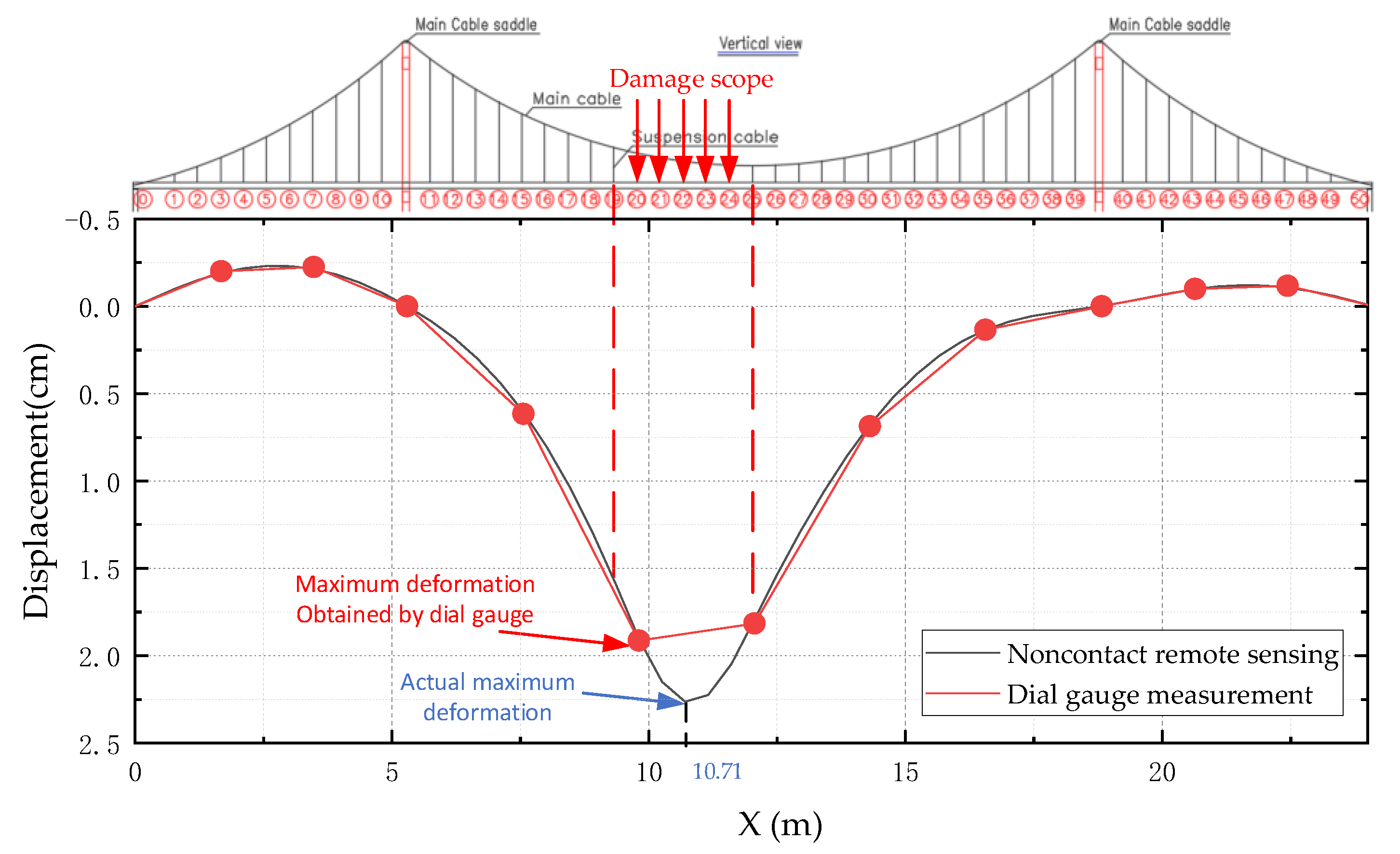
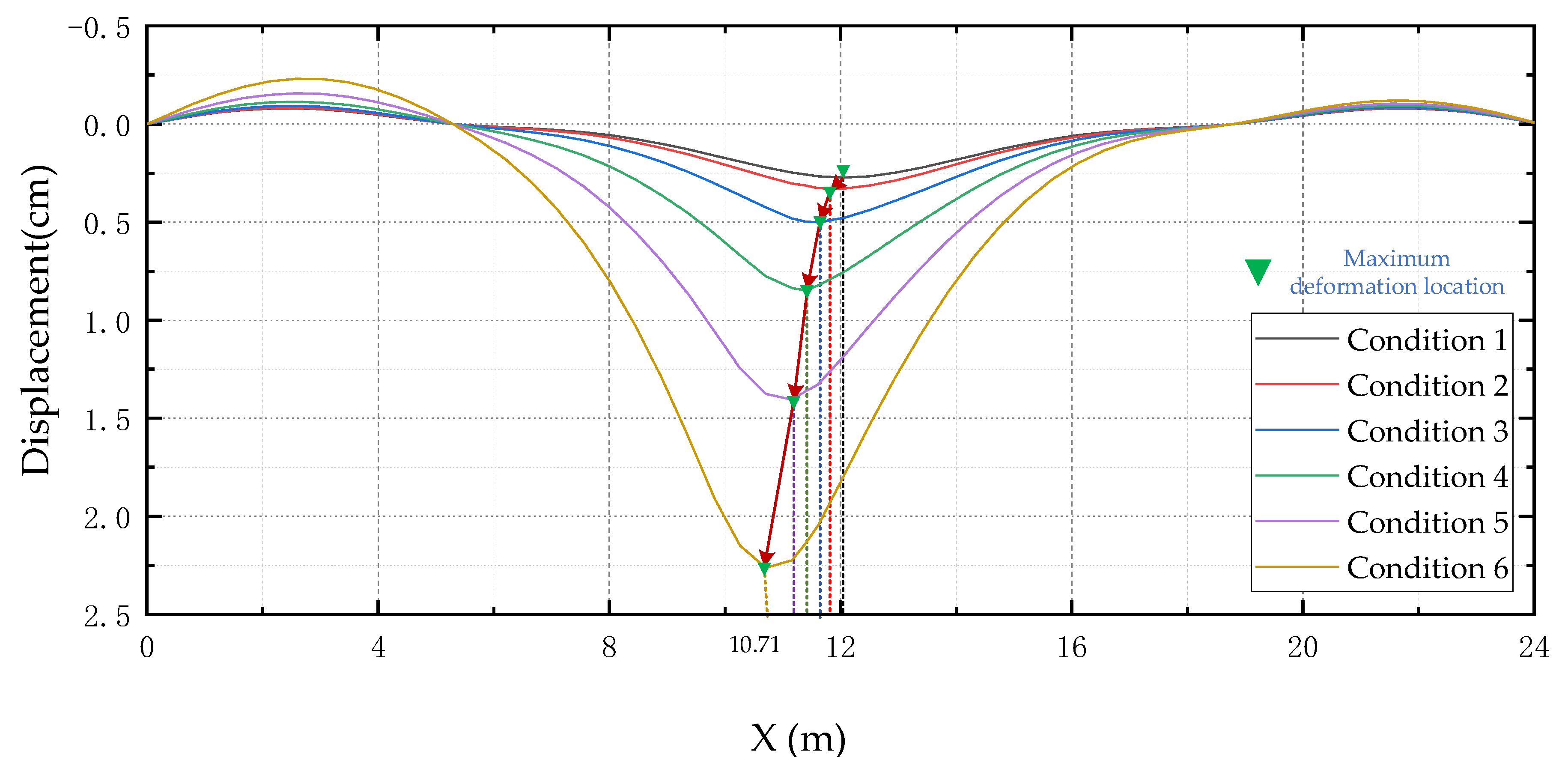
In order to more clearly reflect the advantages of dense full-field displacement, the deformation of the whole bridge girder obtained from NRS under condition 6 is compared with the deformation of the whole bridge girder obtained from nine dial indicators, as shown in Figure 19. The comparison of Figure 19 and Table 3, it can be derived that the position with the maximum deformation in Table 3 is the measuring point 4, but the position with the maximum deformation of the actual test bridge is the position with the length of 10.71m between the measuring points 5 and 4; the comparison of the six working conditions, it can be derived that the position with the maximum deformation of the girder changes under different damage conditions, as shown in Figure 20. If the contact sensor, such as the dial gauge is used for measurement, a reasonable arrangement way of obtaining the deformation characteristics of the bridge structure from the finite points is difficult to determine. One arrangement approach cannot meet the deformation characteristics of the bridge structure caused by the change of structural stiffness at different positions. The noncontact remote measurement method used in this paper can capture the pixel level change of any position of the bridge structure, the accuracy can meet the requirements of engineering application, and the advantages are obvious. Meanwhile, model updating according to more accurate line shape can make the model closer to the real bridge, increasing the authenticity and credibility of the finite element calculation results, and exerting the same positive significance on the application of digital twin. The dense full-field displacement monitoring provides a larger amount of real data, which is the basis of machine learning. Using this method for regular or long-term monitoring can obtain a larger amount of real data than traditional ways, laying the foundation for using machine learning for structural health monitoring.

6. Conclusions

In this study, the dense full-field deformation of a reduced-scale model for a 24m-span self-anchored suspension bridge under multiple damage conditions was captured with the noncontact remote measurement method in a multi visual field. The spatiotemporal sequence static image data under different work conditions were collected to establish the relationship between spatial and temporal. Furthermore, the dense full-field displacement monitoring data of the girder of the test bridge were obtained, and compared with the finite element calculation results. The measurement results of the dial gauge displacement meter were compared. The main conclusions are as follows:
(1)
A fixed point uniaxial automatic cruise acquisition device was designed to collect the static images of the bridge façade under different damage conditions. Then, the spatiotemporal sequences of static images were processed by the edge detection method, the edge pixel virtual marker point, the SIFT algorithm and the optical flow algorithm to obtain a dense full-field displacement of the whole test bridge girder, which can be used as the data base to make the structural health monitoring technology more economical, efficient and direct. Compared with other monitoring methods, the girder dense points displacement information provides a data-base for more accurate model updating and damage identification. Meanwhile, the technology proposed in this paper is low-cost and can be used as a long-term regular monitoring method to accumulate massive real structural displacement information and provide big data set for the subsequent study of machine learning for damage identification.
(2)
The optical flow algorithm, which is widely used in video analysis, was used in the static image data set to track the target and calculate the displacement, overcoming the shortcomings of many manual interventions in the early stage of research group. Meanwhile, the number of monitoring points remains the same (i.e. the displacement of each pixel of the lower edge contour line of the girder). The output data are basically consistent with the finite-element prediction and dial gauge measurement. The global holographic deformation curves of the test bridge exhibit similar trends under different damage conditions, with an error of less than 12%. This means that the proposed method in this paper satisfies the engineering requirement on measurement accuracy.
(3)
A new method of making a virtual target was used. The coordinates of the required lower edge contour of the girder were extracted and then used it to make the pixels of the initial image of the lower edge of the girder as a virtual target back, and then track and calculate the displacement information of all pixels of the contour through the optical flow algorithm. Although this method needs a certain amount of manual intervention in the early stage, it can locate accurately and obtain more measuring point displacement simultaneously.
(4)
The information obtained from the combination of several points does not really reflect the structural deformation characteristics of the bridge under different damage conditions, and the abnormal local deformation information caused by the damage will be lost. Thus, the dense full-field displacement information is more sensitive to the structural stiffness change.
(5)
The characteristics of the linear change of the test bridge under different damage conditions indicate a strong correlation between the damage location and degree and the linear change. The relationship between the three can be established, and the method of amplifying the damage and deformation characteristics and carrying out the quantification requires further study.
(6)
This work is only the first exploration of the dense full-field displacement monitoring of the whole bridge girder using NRS. It involves less in the optimization of parameters in the experiment, less in the improvement of the algorithm and the accuracy of the algorithm, which needs to be further studied in the future. Meanwhile, it only shows that the dense full-field displacement is more sensitive to the damage identification, but the damage identification is not involved.

Author Contributions

Conceptualization, Z.Z.; formal analysis, G.D.; investigation, X.C.; methodology, G.D.; resources, G.D., S.S. and C.J.; writing – original draft, G.D.; writing – review and editing, G.D. and S.S. All authors have read and agreed to the published version of the manuscript.

Funding

This research was funded by the National Natural Science Foundation of China, grant number 51778094, the National Science Foundation for Distinguished Young Scholars of China, grant number 51608080, the National Science Foundation for Distinguished Young Scholars of China, grant number 51708068, and the Science and Technology Innovation Project of Chongqing Jiaotong University, grant number 2019S0141.

Acknowledgments

Special thanks to J.L. Heng at the Shenzhen University, and Y.M. Gao at the State Key Laboratory of Mountain Bridge and Tunnel Engineering, and Chongqing Jiaotong University.

Conflicts of Interest

The authors declare no conflict of interest.

References

  1. Editorial Department of China Journal of Highway and Transport. Review on China’s Bridge Engineering Research: 2014. China J. Highw. Transp. 2014, 27, 1–96. [Google Scholar]
  2. He, S.-H.; Zhao, X.-M.; Ma, J.; Zhao, Y.; Song, H.-S.; Song, H.-X.; Cheng, L.; Yuan, Z.-Y.; Huang, F.-W.; Zhang, J.; et al. Review of Highway Bridge Inspection and Condition Assessment. China J. Highw. Transp. 2017, 30, 63–80. [Google Scholar]
  3. Nhat-Duc, H. Detection of Surface Crack in Building Structures Using Image Processing Technique with an Improved Otsu Method for Image Thresholding. Adv. Civ. Eng. 2018, 2018, 3924120. [Google Scholar]
  4. Li, H.; Bao, Y.-Q.; Li, S.-L. Data Science and Engineering Structural Health Monitoring. J. Eng. Mech. 2015, 32, 1–7. [Google Scholar]
  5. Bao, Y.-Q.; James, L.B.; Li, H. Compressive Sampling for Accelerometer Signals in Structural Health Monitoring. Struct. Health Monit. 2011, 10, 235–246. [Google Scholar]
  6. Gul, M.; Dumlupinar, T.; Hattori, H.; Catbas, N. Structural monitoring of movable bridge mechanical components for maintenance decision-making. Struct. Monit. Maint. 2014, 1, 249–271. [Google Scholar] [CrossRef]
  7. Gul, M.; Catbas, F.N.; Hattori, H. Image-based monitoring of open gears of movable bridges for condition assessment and maintenance decision making. J. Comput. Civ. Eng. 2015, 29, 04014034. [Google Scholar] [CrossRef]
  8. Garcia-Palencia, A.; Santini-Bell, E.; Gul, M.; Çatbaş, N. A FRF-based algorithm for damage detection using experimentally collected data. Struct. Monit. Maint. 2015, 24, 399–418. [Google Scholar] [CrossRef]
  9. Spencer, B.F., Jr.; Hoskere, V.; Narazaki, Y. Advances in computer vision-based civil infrastructure inspection and monitoring. Engineering 2019, 5, 199–222. [Google Scholar] [CrossRef]
  10. Yang, Y.; Jung, H.K.; Dorn, C.; Park, G.; Farrar, C.; Mascareñas, D. Estimation of full-field dynamic strains from digital video measurements of output-only beam structures by video motion processing and modal superposition. Struct. Control Health Monit. 2019, 26, e2408. [Google Scholar] [CrossRef]
  11. Kim, H.; Shin, S. Reliability verification of a vision-based dynamic displacement measurement for system identification. J. Wind Eng. Ind. Aerod. 2019, 191, 22–31. [Google Scholar] [CrossRef]
  12. Ojio, T.; Carey, C.H.; Obrien, E.J.; Doherty, C.; Taylor, S.E. Contactless bridge weigh-in-motion. J. Bridge Eng. 2016, 217, 04016032. [Google Scholar] [CrossRef] [Green Version]
  13. Moreu, F.; Li, J.; Jo, H.; Kim, R.E. Reference-free displacements for condition assessment of timber railroad bridges. J. Bridge Eng. 2016, 21, 04015052. [Google Scholar] [CrossRef]
  14. Xu, Y.; Brownjohn, J.; Kong, D. A non-contact vision-based system for multipoint displacement monitoring in a cable-stayed footbridge. Struct. Control Health Monit. 2018, 25, e2155. [Google Scholar] [CrossRef] [Green Version]
  15. Hester, D.; Brownjohn, J.; Bocian, M.; Xu, Y. Low cost bridge load test: Calculating bridge displacement from acceleration for load assessment calculations. Eng. Struct. 2017, 143, 358–374. [Google Scholar] [CrossRef] [Green Version]
  16. Celik, O.; Dong, C.Z.; Catbas, F.N. A computer vision approach for the load time history estimation of lively individuals and crowds. Comput. Struct. 2018, 200, 32–52. [Google Scholar] [CrossRef]
  17. Catbas, F.N.; Zaurin, R.; Gul, M.; Gokce, H.B. Sensor networks, computer imaging, and unit influence lines for structural health monitoring: Case study for bridge load rating. J. Bridge Eng. 2012, 17, 662–670. [Google Scholar] [CrossRef]
  18. Khuc, T.; Catbas, F.N. Structural identification using computer vision–based bridge health monitoring. J. Struct. Eng. 2018, 144, 04017202. [Google Scholar] [CrossRef]
  19. Dong, C.Z.; Celik, O.; Catbas, F.N. Marker-free monitoring of the grandstand structures and modal identification using computer vision methods. Struct. Health Monit. 2019, 18, 1491–1509. [Google Scholar] [CrossRef]
  20. Yang, Y.; Dorn, C.; Mancini, T.; Talkend, Z.; Kenyone, G.; Farrara, C.; Mascareñasa, D. Blind identification of full-field vibration modes from video measurements with phase-based video motion magnification. Mech. Syst. Signal Process. 2017, 85, 567–590. [Google Scholar] [CrossRef]
  21. Bao, Y.-Q.; Bao, Y.-Q.; Ou, J.; Li, Hui. Emerging Data Technology in Structural Health Monitoring: Compressive Sensing Technology. J. Civ. Struct. Health Monit. 2014, 4, 77–90. [Google Scholar] [CrossRef]
  22. Bao, Y.-Q.; Li, H.; Sun, X.-D.; Ou, J.-P. A Data Loss Recovery Approach for Wireless Sensor Networks Using a Compressive Sampling Technique. Struct. Health Monit. 2013, 12, 78–95. [Google Scholar] [CrossRef]
  23. Bao, Y.-Q.; Zou, Z.-L.; Li, H. Compressive Sensing Based Wireless Sensor for Structural Health Monitoring; 90611W-1-10; SPIE Smart Structures/NDE: San Diego, CA, USA, 2014. [Google Scholar]
  24. Bao, Y.-Q.; Yan, Y.; Li, H.; Mao, X.; Jiao, W.; Zou, Z.; Ou, J. Compressive Sensing Based Lost Data Recovery of Fast-moving Wireless Sensing for Structural Health Monitoring. Struct. Control Health Monit. 2014, 22, 433–448. [Google Scholar] [CrossRef]
  25. Guzman-Acevedo, G.M.; Becerra, G.E.V.; Millan-Almaraz, J.R.; Rodríguez-Lozoya, H.E.; Reyes-Salazar, A.; Gaxiola-Camacho, J.R.; Martinez-Felix, C.A. GPS, Accelerometer, and Smartphone Fused Smart Sensor for SHM on Real-Scale Bridges. Adv. Civ. Eng. 2019, 2019, 6429430. [Google Scholar] [CrossRef]
  26. Xu, Y.; Brownjohn, J.M.W. Review of machine-vision based methodologies for displacement measurement in civil structures. J. Civ. Struct. Health Monit. 2018, 8, 91–110. [Google Scholar] [CrossRef] [Green Version]
  27. Feng, D.; Feng, M.Q.; Ozer, E.; Fukuda, Y. A vision-based sensor for noncontact structural displacement measurement. Sensors 2015, 15, 16557–16575. [Google Scholar] [CrossRef] [PubMed]
  28. Feng, D.; Feng, M.-Q. Identification of structural stiffness and excitation forces in time domain using noncontact vision-based displacement measurement. J. Sound Vib. 2017, 406, 15–28. [Google Scholar] [CrossRef]
  29. Feng, D.; Scarangello, T.; Feng, M.-Q.; Ye, Q. Cable tension force estimate using novel noncontact vision-based sensor. Measurement 2017, 99, 44–52. [Google Scholar] [CrossRef]
  30. Dong, C.Z.; Ye, X.W.; Jin, T. Identification of structural dynamic characteristics based on machine vision technology. Measurement 2018, 126, 405–416. [Google Scholar] [CrossRef]
  31. Ye, X.-W.; Dong, C.-Z.; Liu, T. A review of machine vision-based structural health monitoring: Methodologies and applications. J. Sens. 2016, 2016, 7103039. [Google Scholar] [CrossRef] [Green Version]
  32. Khuc, T.; Catbas, F.N. Computer vision-based displacement and vibration monitoring without using physical target on structures. Struct. Infrastruct. Eng. 2017, 13, 505–516. [Google Scholar] [CrossRef]
  33. Tian, L.; Pan, B. Remote bridge deflection measurement using an advanced video deflectometer and actively illuminated LED targets. Sensors 2016, 16, 1344. [Google Scholar] [CrossRef] [PubMed] [Green Version]
  34. Lee, J.J.; Cho, S.; Shinozuka, M.; Yun, C.; Lee, C.; Lee, W. Evaluation of bridge load carrying capacity based on dynamic displacement measurement using real-time image processing techniques. Int. J. Steel Struct. 2006, 6, 377–385. [Google Scholar]
  35. Feng, D.; Feng, M.-Q. Model updating of railway bridge using in situ dynamic displacement measurement under trainloads. J. Bridge Eng. 2015, 20, 04015019. [Google Scholar] [CrossRef]
  36. Chen, J.-G.; Adams, T.M.; Sun, H.; Bell, E.S. Camera-based vibration measurement of the world war I memorial bridge in portsmouth, New Hampshire. J Struct. Eng. 2018, 144, 04018207. [Google Scholar] [CrossRef]
  37. Abraham, L.; Sasikumar, M. Analysis of satellite images for the extraction of structural features. IETE Tech. Rev. 2014, 31, 118–127. [Google Scholar] [CrossRef]
  38. Milillo, P.; Perissin, D.; Salzer, J.-T.; Lundgren, P.; Lacava, G.; Milillo, G.; Serio, C. Monitoring dam structural health from space: Insights from novel InSAR techniques and multi-parametric modeling applied to the Pertusillo dam Basilicata, Italy. Int. J Appl. Earth Obs. Geoinf. 2016, 52, 221–229. [Google Scholar] [CrossRef]
  39. Wang, S.-R.; Zhou, Z.-X.; Gao, Y.-M.; Xu, J. Newton-Raphson Algorithm for Pre-offsetting of Cable Saddle on Suspension Bridge. China J. Highw. Transp. 2016, 29, 82–88. [Google Scholar]
  40. Wang, S.-R.; Zhou, Z.-X.; Wu, H.-J. Experimental Study on the Mechanical Performance of Super Long-Span Self-Anchored Suspension Bridge in Construction Process. China Civ. Eng. J. 2014, 47, 70–77. [Google Scholar]
  41. Wang, S.-R.; Zhou, Z.-X.; Wen, D.; Huang, Y. New Method for Calculating the Pre-Offsetting Value of the Saddle on Suspension Bridges Considering the Influence of More Parameters. J. Bridge Eng. 2016, 2016, 06016010. [Google Scholar] [CrossRef]
  42. Zhang, Z.-Y. A flexible new technique for camera calibration. IEEE Trans. Pattern Anal. Mach. Intell. 2000, 22, 1330–1334. [Google Scholar] [CrossRef] [Green Version]
  43. Zhang, Z.-Y. Camera calibration with one-dimensional objects. IEEE Trans. Pattern Anal. Mach. Intell. 2004, 26, 892–899. [Google Scholar] [CrossRef] [PubMed]
  44. Mezirow, J. Perspective Transformation. Adult Educ. Q. 2014, 28, 100–110. [Google Scholar] [CrossRef]
  45. Deng, G.-J.; Zhou, Z.-X.; Chu, X.; Lei, Y.-K.; Xiang, X.-J. Method of bridge deflection deformation based on holographic image contour stacking analysis. Sci. Technol. Eng. 2018, 18, 246–253. [Google Scholar]
  46. Grabner, M.; Grabner, H.; Bischof, H. Fast approximated SIFT. ACCV 2006, 3851, 918–927. [Google Scholar]
  47. Liu, Y.; Liu, S.-P.; Wang, Z.-F. Multi-focus image fusion with dense SIFT. Inf. Fusion 2015, 23, 139–155. [Google Scholar] [CrossRef]
  48. Lucena, M.J.; Fuertes, J.M.; Gomez, J.I.; de la Blanca, N.P.; Garrido, A. Optical flow-based probabilistic tracking. In Seventh International Symposium on Signal Processing and Its Applications; IEEE: New York, NY, USA, 2003. [Google Scholar]
  49. Roth, S.; Black, M.J. On the Spatial Statistics of Optical Flow. Int. J. Comput. Vis. 2007, 74, 33–50. [Google Scholar] [CrossRef]
  50. Horn, B.K.P.; Schunck, B.G. Determining optical flow. Artif. Intell. 1981, 17, 185–203. [Google Scholar] [CrossRef] [Green Version]
Figure 1. (a)The architecture of the intelligent noncontact remote sensing (NRS) system; (b) the intelligent NRS system for our load tests.
Applsci 10 02118 g001
Figure 2. The workflow of the intelligent NRS system.
Applsci 10 02118 g002
Figure 3. The standard section diagram of a girder model (unit: Mm).
Applsci 10 02118 g003
Figure 4. Section at lifting point of main beam (unit: Mm).
Applsci 10 02118 g004
Figure 5. Schematic plan view of the main beam (unit: Mm).
Applsci 10 02118 g005
Figure 6. The reduced-scale model.
Applsci 10 02118 g006
Figure 7. The layout of the lab.
Applsci 10 02118 g007
Figure 8. The principle of image collection.
Applsci 10 02118 g008
Figure 9. The arrangement of dial gauges.
Applsci 10 02118 g009
Figure 10. Serial number of suspension cables.
Applsci 10 02118 g010
Figure 11. Finite element model of test bridge.
Applsci 10 02118 g011
Figure 12. The distribution of the suspender force.
Applsci 10 02118 g012
Figure 13. Flowchart of the MATLAB algorithm.
Applsci 10 02118 g013
Figure 14. The workflow of denoising and marking of bridge contours. Step 1: Edge detection of static images; step 2: Acquisition of bridge contours through decontextualization of useless contours; step 3: Marking the original images based on the coordinates of boundary pixels.
Applsci 10 02118 g014
Figure 15. The spatiotemporal features of static image sequences.
Applsci 10 02118 g015
Figure 16. Description of text bridge feature points.
Applsci 10 02118 g016
Figure 17. Comparison of two methods for obtaining deformation value for different fields of views: (a) Comparison for field of view 1; (b) comparison for field of view 2; (c) comparison for field of view 3; (d) comparison for field of view 4; (e) comparison for field of view 5; (f) comparison for field of view 6.
Applsci 10 02118 g017aApplsci 10 02118 g017b
Figure 18. The global holographic deformation under different damage conditions.
Applsci 10 02118 g018
Figure 19. Comparison of girder alignment obtained by two measure method under condition 6.
Applsci 10 02118 g019
Figure 20. Deformation trend chart.
Applsci 10 02118 g020
Table 1. The positions and numbers of damaged suspension cables.
Serial NumberDamage ConditionsData Collection Method
PositionNumberTraditional MethodVisual Method
100Dial gaugesIntelligent NRS system
2242Dial gaugesIntelligent NRS system
323, 244Dial gaugesIntelligent NRS system
422, 23, 246Dial gaugesIntelligent NRS system
521, 22, 23, 248Dial gaugesIntelligent NRS system
620, 21, 22, 23, 2410Dial gaugesIntelligent NRS system
Table 2. Main material parameters.
Serial NumberItemSection ShapeE (GPa)ftk (MPa)σs (MPa)Poisson’s Ratio
1Main cable1951860/0.3
2suspender1951860/0.3
3Main beam Applsci 10 02118 i001206/3450.3
4main tower206/3450.3
Table 3. Comparison results.
No.Deformation of Stacking Analysis (mm)Measured Deviation %Relative Error %
Dial gauge Measurement
R1
Finite-Element Method
R2
Noncontact Remote Sensing
R3
|R3–R1|/R1|R3–R2|/R2
10.1100.19.09%/
20.9911.089.09%8.00%
31.561.551.687.69%8.39%
45.425.555.878.30%5.77%
517.4617.3218.757.39%8.26%
615.1615.316.438.38%7.39%
75.185.245.679.46%8.21%
80.930.961.029.68%6.25%
90.370.380.4110.81%7.89%
100.350.330.375.71%12.12%
110.0900.0811.11%/