Article

Control Methods Comparison for the Real Quadrotor on an Innovative Test Stand

Institute of Robotics and Cybernetics, Faculty of Electrical Engineering and Information Technology, Slovak Univerzity of Technology, Vazovova 5, 812 43 Bratislava, Slovakia
*
Author to whom correspondence should be addressed.
Appl. Sci. 2020, 10(6), 2064; https://doi.org/10.3390/app10062064
Submission received: 21 February 2020 / Revised: 6 March 2020 / Accepted: 9 March 2020 / Published: 18 March 2020
(This article belongs to the Collection Advances in Automation and Robotics)

Abstract

:
This article is a continuation of our previously published work that presented a comparison of nine attitude quaternion-based controllers of the quadrotor in simulation environment. In this article, the best three controllers were implemented into the real quadrotor. Namely proportional derivative (PD), linear quadratic regulator (LQR) and backstepping quaternion-based control techniques were evaluated. As a suitable test stand was not available on the basis of literature analysis, the article also outlines the requirements and the development of a new innovative test stand. In order to provide a comprehensive overview, the hardware and software that was used is also presented in the article. The main contribution of this article is a performance comparison of the controllers, which was based on absolute quaternion (positioning) error and energy consumption.

1. Introduction

In the last decades interest in unmanned aerial vehicles (UAVs) has increased. These vehicles consist of various flying platforms such as airships, fixed-wing or vertical take-off and landing (VTOL) vehicles. This article is focused on a quadrotor, which belongs to VTOL UAVs.
The main advantage of VTOL UAVs is the ability to hover allowing them to operate in a small and cluttered environment [1]. Comparing a multirotor VTOL platform to a helicopter, several advantages can be identified, such as a greater trust–weight ratio and better maneuverability. The variable number of rotors provide the possibility to use smaller propellers instead of large ones to produce a particular thrust. This leads to less structural and dynamical problems and, in the case of an accident, the resulting injury is usually less heavy [2,3,4]. Moreover, the formation of various quadrotors can perform a complex task such as the transport of items heavier than the maximum permissible load weight of one quadrotor. Multirotor platforms are usually controlled by changing an angular speed of rotors, so there is no need of a swashplate. This simplifies not only the mechanics but also the maintenance of the system [2,3,5]. Multirotor platforms can also continue in flight after occurrence of an actuator failure as long as they are equipped with a failsafe controller. Although the failsafe controller is more straightforward to design for multirotor drones with six or eight rotors, some controllers were also designed to manage an actuator failure of quadrotor. Examples of failsafe controllers for a quadrotor can be found in [6,7,8]. Multirotor platforms have become very popular and their usage has spread over all fields. Some requested tasks can be complicated, and they can require the control algorithms, which are faster, more efficient and reliable also under windy, uncertain and changing conditions. A disturbance observer (DO) is usually designed to compensate such uncertainties.
The quadrotor is coupled and underactuated system (i.e., six degrees of freedom are controlled only by four actuators). The translational motion of the quadrotor depends on the attitude of the quadrotor as can be seen from the equations in [9]. By this means, the quadrotor is a cascade system [10]. Therefore, a cascade structure of a controller is usually applied to control position and attitude of the quadrotor. Various controllers based on classic or modern control theory were already designed and verified. The non-linear or linear model of a quadrotor is used depending on the chosen control method [11].
The linear model of a quadrotor is achieved by linearization of the non-linear model around a hovering point. Controllers using the linearized model generally perform well around this hovering point. When the quadrotor goes away from the linearized point, the performance may worsen. Furthermore, the input saturation can cause control failure when large rapid maneuvers are required [3,5,12,13]. The main advantages of linear controllers are simplicity and ease of implementation to a real platform. The disadvantage of this approach is the use of the linearized model of the quadrotor during the process of designing a controller. Commonly used linear controllers are a linear quadratic regulator (LQR) and a proportional derivative (PD) controller [14,15,16].
Another group of controllers consists of a wide variety of non–linear controllers. The serious disadvantage of these controllers is the complexity that prevents the wide adoption of non-linear controllers in real applications. Among non-linear methods, the backstepping control technique based on the Lyapunov function is widely adopted due to its systematic design and an intuitive approach [17]. The proposed control law is based on the compensation of non-linear forces or torques depending on whether an attitude or position controller is being designed. Applying Lyapunov stability analysis proves that the closed-loop system is asymptotically stable. This approach was used to stabilize the quadrotor in [3,5,12,18,19,20,21].
A backstepping-based inverse optimal attitude controller (BIOAC) was derived in [3] taking into account the input saturation. In [12], command filters are used to avoid a difficult analytic computation of required command derivatives in each step. The double-integral observer was developed in [18] to design a control law based on the Lyapunov function to track a reference trajectory. A decoupling attitude parameterization was presented in [19]. It allows the design of an independent and straightforward position heading tracking control using the backstepping control technique.
Some works try to overcome uncertainties (e.g., sensor noise, parametric uncertainties and external disturbance) by designing adaptive controllers [22,23]. In another recent work [24] a flight controller based on a Neural Network model has been presented for stabilization and trajectory control. Using an AI-based controller seems promising. Several works using these control techniques can be found in [25,26,27].
Quaternion describing dynamics of a quadrotor instead of Euler angles is becoming very popular nowadays. A feedback signal in the form of a quaternion can be used to design linear and also non-linear attitude and position controllers [28,29].
In [13], a cascade attitude controller was proposed. Both an inner and an outer control loop were formed by proportional controllers. The angular velocity and the quaternion were used as feedback signals. From this combination an attitude P2-controller arose. However, the final control law of the P2-controller corresponds to the standard PD controller designed in [2,30].
The problem of disturbance rejection of the attitude subsystem of a quadrotor was addressed in [1]. An acceleration-based disturbance observer was applied to a quaternion-based integral sliding mode attitude controller. This combination shows a significant improvement of the performance in position control as well as the compensation of large external forces.
Generally, many studies where a review of control techniques can be found. Such studies are addressed in [22,23,31]. Most of them are pointing out their advantages and disadvantages, but the experiments with the same UAV model and various control techniques are missing in the literature. Authors and scientists usually improve one technique and compare it with the technique from which the proposal originated. For example, authors in [32] improved backstepping controller by own proposed method called robust and saturated backstepping controller (RAS-BSC). Consequently, objective information expressed in the exact control quality indicators is missing and various control techniques cannot be compared in the more objective manner.
From this reason, our previous work [9] compared various quaternion-based control methods applied to quadrotor with disturbance observer and position estimator. The comparison was based on simulation results and the results brought qualitative new knowledge, because the objective quality indicators were chosen in order to compare the performance of all controllers. In total, nine control techniques (controllers) were compared.
In this article we present a logical outcome of our work. Based on the results in [9], three of the most promising control techniques were chosen (PD, LQR and backstepping) and they were implemented and evaluated on the real quadrotor. However, from the reasons specified in the 
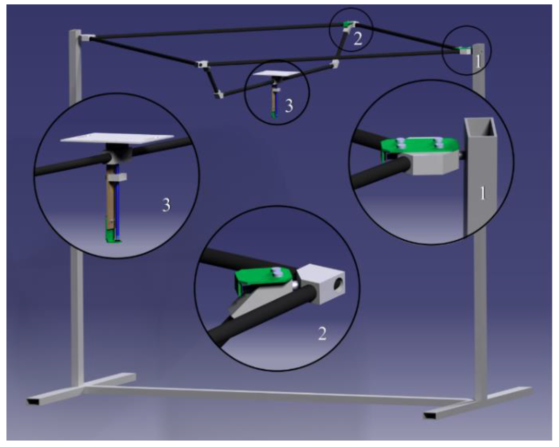
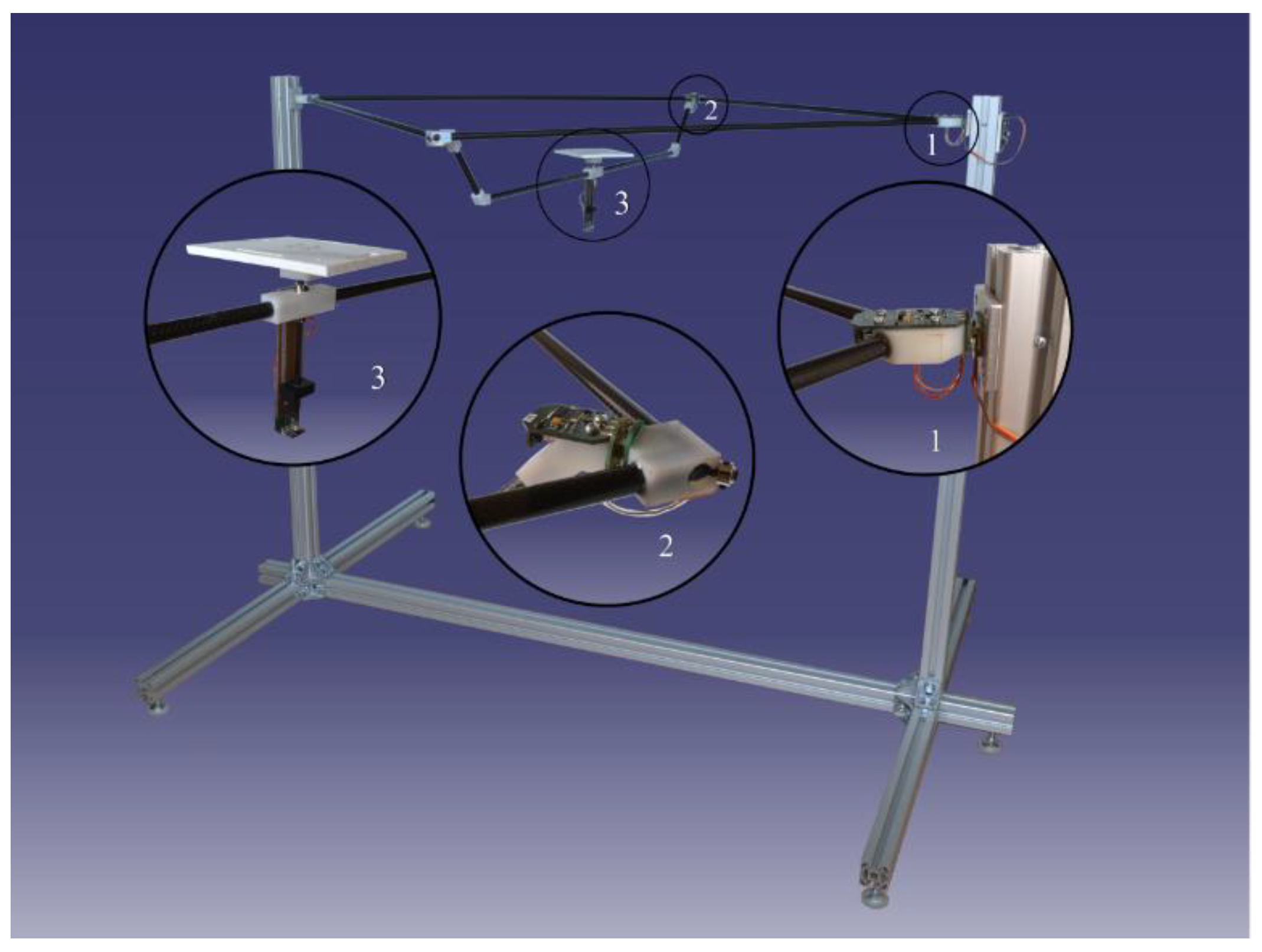
Section 2.2 a test stand suitable for the complex evaluation of these controllers was not available. We designed an innovative test stand, which is registered as a utility model no. 7766 in Slovak Republic [33]. The control techniques were evaluated by 15 quality indicators and as far as we know, such complex comparison of PD, LQR and backstepping control techniques were not published yet. Moreover, all these techniques are quaternion-based, which is also significant contribution of this paper.
The article is structured as follows: Two test stands are presented in Section 2. First stand was used for an identification of static and dynamic characteristics of the actuator used in the real quadrotor. This test stand is a standard one and its description provides only basic information about the used platform. Second stand is an innovative stand mentioned above. Our goal was to suppress the momentum of inertia when designing this stand as much as possible. Moreover, this stand allows to test the quadrotor in 3 DOF (roll, pitch, yaw) in real-time. In analysis provided in Section 2.2, available test stands are investigated. Due to several disadvantages, we decided to design a completely new test, which is described in Section 2.2. The Section 3 presents a performance comparison of the controllers implemented in the real quadrotor. Finally, the conclusion is included in the end of this article.

2. Design of Test Stands

2.1. Test Stand for Identification of Static and Dynamic Characteristics of the Actuator

Parameters used in the derived mathematical model in our previous work [9] were obtained from the static and dynamic characteristics of the real actuators. In this work [9] several controllers were tested in simulation environment. The next logical step was to evaluate selected controllers on the real quadrotor platform. That is why this section will present the first stand, which was used to identify static and dynamic characteristics of the actuators. The main contribution of this stand is significantly lower price compared to standard test stands, without loss of the identification quality.
In order to identify coefficients of the actuators, namely the thrust coefficient and the drag coefficient, the relation between the force/torque and rotor speed or PWM (pulse width modulation) sent to ESC (electronic speed controller) must be measured. Test stands used by other researchers normally consist of a six-axes torque/force sensor or load cell, a pivot arm, tachometer and actuator. In [34], the identification was focused only on a motor itself without considering an ESC. In [35], the dynamics of an actuator was concerned when the propeller or ESC was changed. The price range of the used sensors varied from 400 to 1300 € [36,37,38,39,40,41].
A low-cost measuring test stand was designed to measure force, torque, battery voltage and current, so that complete identification including motor dynamics could be established. Mechanical construction of the test stand (Figure 1) consists of a large wooden board, an arm of the quadrotor frame, a binocular beam load cell, an optical sensor and the actuator. The wooden board is used to fix the whole construction to the ground or another base during the measurement. The arm of a DJI Flame Wheel F450 is used to ensure that the measurement will be under the same aerodynamic conditions as during the flight. The load cell, which can be found in most kitchen scales, is attached to the arm. Maximum load capacity of the load cell is 5 kg. Its output transfer sensitivity is 1 mV per 1 V of excitation voltage at full load. The binocular beam load cell incorporates a full-bridge configuration of strain gauges. Because of the two holes in the middle of the load cell, it can measure only vertical deformation and the length of the arm is not taken into account during the measurement. The usage of four strain gauges ensures compensation of the unwanted temperature effect on the output signal and increases measuring sensitivity. The approximated price of this test stand is 60 €.
For the experiments, the DJI BLDC motor was used and it was firmly attached to the load cell. The BLDCM belongs to the 2212 power class. The power class determines the power of a motor and its diameter (28 mm). The voltage constant of the motor is 920 Kv and nominal current ranges from 15 to 25 A. The use of a 3- or 4-cell lithium polymer battery (LiPo) is recommended. A DJI clockwise propeller 10” × 4.5” was mounted to the motor and a 3-cell LiPo battery with the nominal voltage of 11.1 V was used. The motor is powered by the 30 A ESC from DJI. The input signal for the ESC is a PWM with refresh rate range from 30 to 450 Hz. Power supply and the control signal are obtained from the DAQCB (data acquisition and control board).
If a propeller with two blades is used, there are only two increments per revolution when using a tachometer. In order to obtain higher resolution an encoder was used to measure the motor speed. For this purpose, the outer side of the motor was covered with a sequence of 22 black and white stripes.
The input-output DAQCB was developed to amplify the output signal from the load cell and to gather other signals. The board connects the object of measurement (ESC, BLDCM, battery) with the I/O board MF624 from Humusoft. MF624 consists of an ADC (analog-to-digital converter) and a DAC (digital-to-analog converter) with 14 bit resolution and a timer/counter gate, which is suitable for counting pulses from the reflective optical sensor. The real advantage of MF624 is its support of the MATLAB Simulink environment. A created Simulink model uses the Real-Time Toolbox to collect data from the board and to create a setpoint for the ESC.
Figure 2 shows the block diagram of the created DAQCB. The design of the board allows its use without an external DAQ board in a PC. The heart of the board is an Atmel ATmega16A microcontroller. Using the USB interface, which creates a virtual serial line, the board is able to receive control commands and send measured data. The ATmega16A contains only a 10 bit converter compared to the 14 bit one in the MF624 board, but for the purpose of the identification this resolution is sufficient.
An instrumental amplifier is used to process the signal from the full-bridge configuration of strain gauges. The amplifier gain can be changed using one of three positions of a jumper, thus required sensibility can be reached. The output of the instrumental amplifier is processed by a second-order filter with Butterworth response and unity gain. The filter is comprised of an operational amplifier with the cut-off frequency calculated using the Nyquist–Shannon theorem. Choosing the sampling frequency equal to 100 Hz, the cut-off frequency is set to 50 Hz. The excitation voltage of the full-bridge configuration of strain gauges is created by amplifying the 1.2 V reference voltage using the non-inverting mode of the operational amplifier. This configuration is chosen to stabilize the excitation voltage at 6.12 V.
Measurement of the current consumed by the motor was performed using a Hall effect-based linear current sensor IC ACS712. Because of the small resistance (1.2 mΩ), voltage drop and power loss is minimized. The sensor can measure current up to 30 A and can be used in combination with a filter capacitor. The output voltage of the ACS712 is proportional to the current. It contains an offset to measure negative current, although this should never occur under normal conditions. Another function of the microcontroller is the conversion of the control voltage from the MF624 to a PWM signal sent to the ESC using the following equation:
p = 1000 + 99.5U_PWM.
UPWM is the control voltage and p [μs] is the pulse width sent to the ESC. Zero power is represented by the value of 1 ms and full power by the value of 2 ms. The PWM signal is calculated with a resolution of 8 bits and sent to the ESC with a refresh rate of 250 Hz.
A safety button was also implemented into the DAQCB. Its function is to block the control signal for the ESC, so if something unexpected happens, the motor can be stopped by pushing this button. When the button is pushed the ESC receives a zero-power signal.
Before measuring thrust, the calibration of the load cell with amplifiers must be done. Therefore, the frame arm with the load cell and the actuator was turned upside down. Precise weights of different mass were hung on the actuator to identify the relationship between measured voltage and weight (Figure 3). The offset of the measured weight is caused by the mounted actuator and should be removed before the measurement.

2.2. Test Stand for Verification of Control Techniques

The second test stand was used to verify and evaluate the control technique applied to a real quadrotor. Before the design of an own test stand, several already existing test stands were analyzed. Table 1 lists the comparison of test stands focusing on DOFs and testing range. The innovative design of a new test stand taken into account the following requirements: increased safety (protect quadrotor and its surroundings), 6 DOF and minimal momentum of inertia. Designed test stand provides absolute information about orientation of the quadrotor during verifying designed attitude controllers.
The designed test stand was comprised of two parts—an unmoving metal part which holds a rotary part which can rotate around all three axes. It can be used to mount and; therefore, to test any VTOL platform whereby the maximum dimension is not greater than 0.75 m, including the length of propellers. The rotary part was comprised of carbon tubes and polymer parts including the ball bearings (Figure 4/Figure 5 part 1, 2 and 3). Magnetic rotary sensors are mounted on these polymer parts and provide the following measurements: pitch, roll, yaw and their corresponding angular velocities. VTOL platform can be mounted on a plate with dimension 0.1 × 0.1 m in the center of the test stand. The quadrotor can be adjusted in z axis so that the plane of the propellers contains the x and y axis of rotation of the test stand. The module 1 measures roll, module 2 measures pitch and module 3 measures yaw angle (Figure 4 and Figure 5). All modules are powered from external power supply via cables which are laid inside the carbon tubes. The transition between moving parts is provided through the rotary contacts. Figure 4 shows a test stand designed in CAD software and the real prototype is shown in Figure 5.
The communication scheme is shown in Figure 6. The stand was comprised of four modules, from which three are slaves used to measure orientation represented by blocks 1, 2 and 3 in Figure 4 and Figure 5. The function of the fourth master module is to collect data from slave modules and send it to the superior system represented by block 5 in Figure 6. Modules communicate between each other via one wire interface represented by the element 6 in Figure 6. The communication between the superior system and the stand is established via USB interface represented by the element 7 in Figure 6. One wire serial communication interface was used to send and receive measured data between all units. A cyclic redundancy check (CRC) was used to ensure that the received data are valid.
This new and innovative stand has various advantages in comparison with the stand currently on the market. The main advantage of the stand is that the tested VTOL can rotate in all three axes without restriction. An absolute rotary position sensor was used for the measurement of the orientation. This type of the sensor does not suffer from the drift and provide the absolute orientation of the tested VTOL. This means that the stand can also be used to calibrate the IMU sensor mounted on the VTOL. Even though the lightweight materials were used to build out the stand, the moment of inertia around the x axis still have impact on the dynamics of the tested VTOL. The moments of inertia around all axes of the stand were calculated using CAD software CATIA and they are revealed in Table 2.

3. Experimental Setup and Results

3.1. The Quadrotor Platform

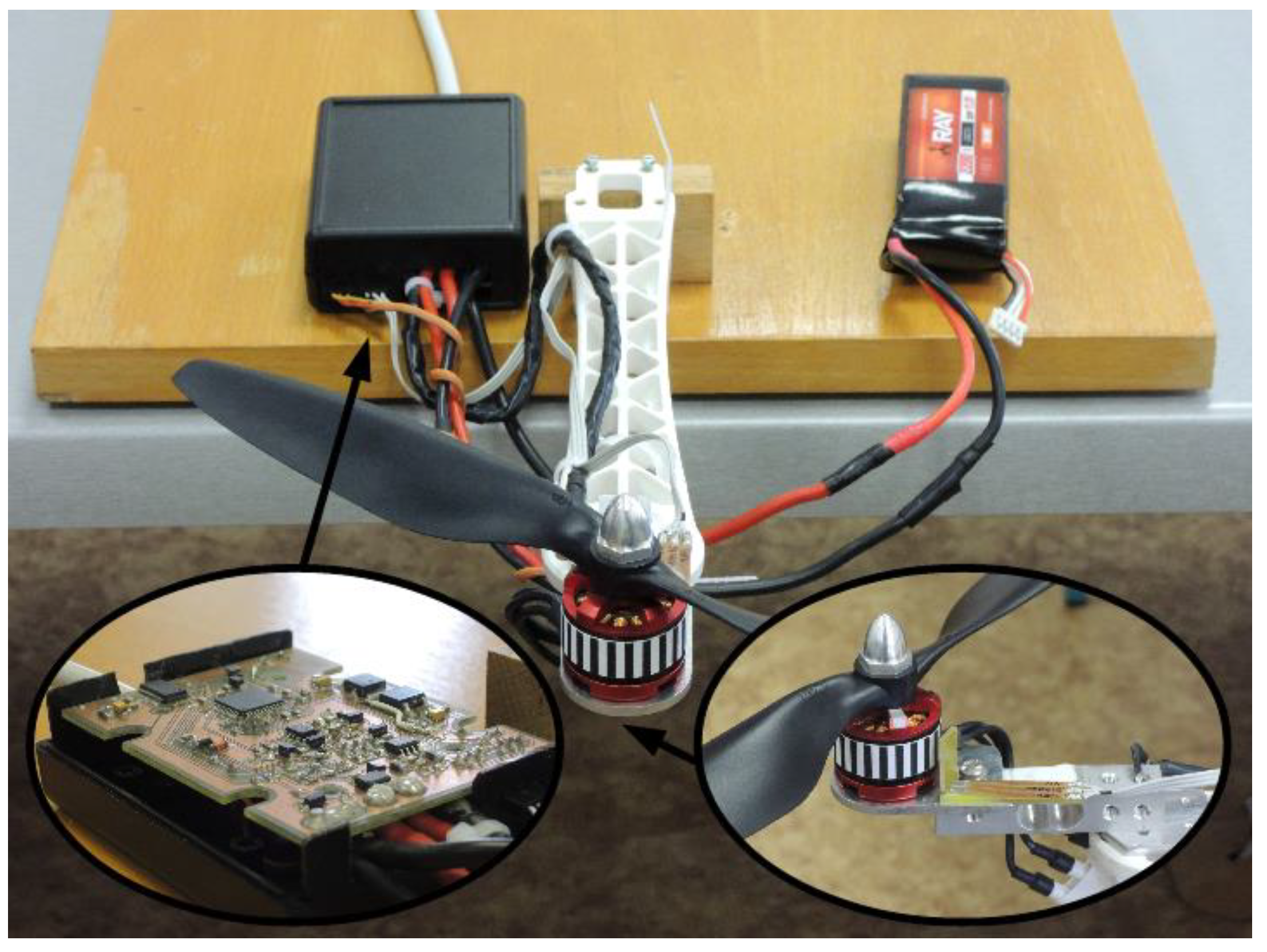
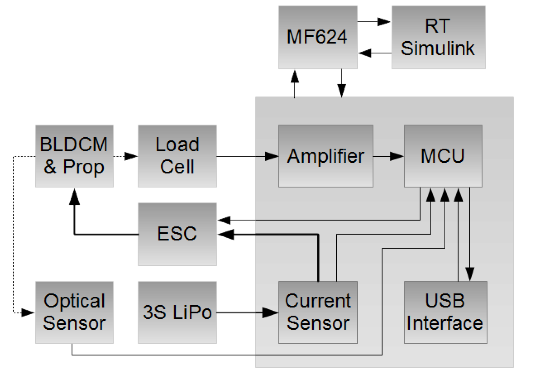
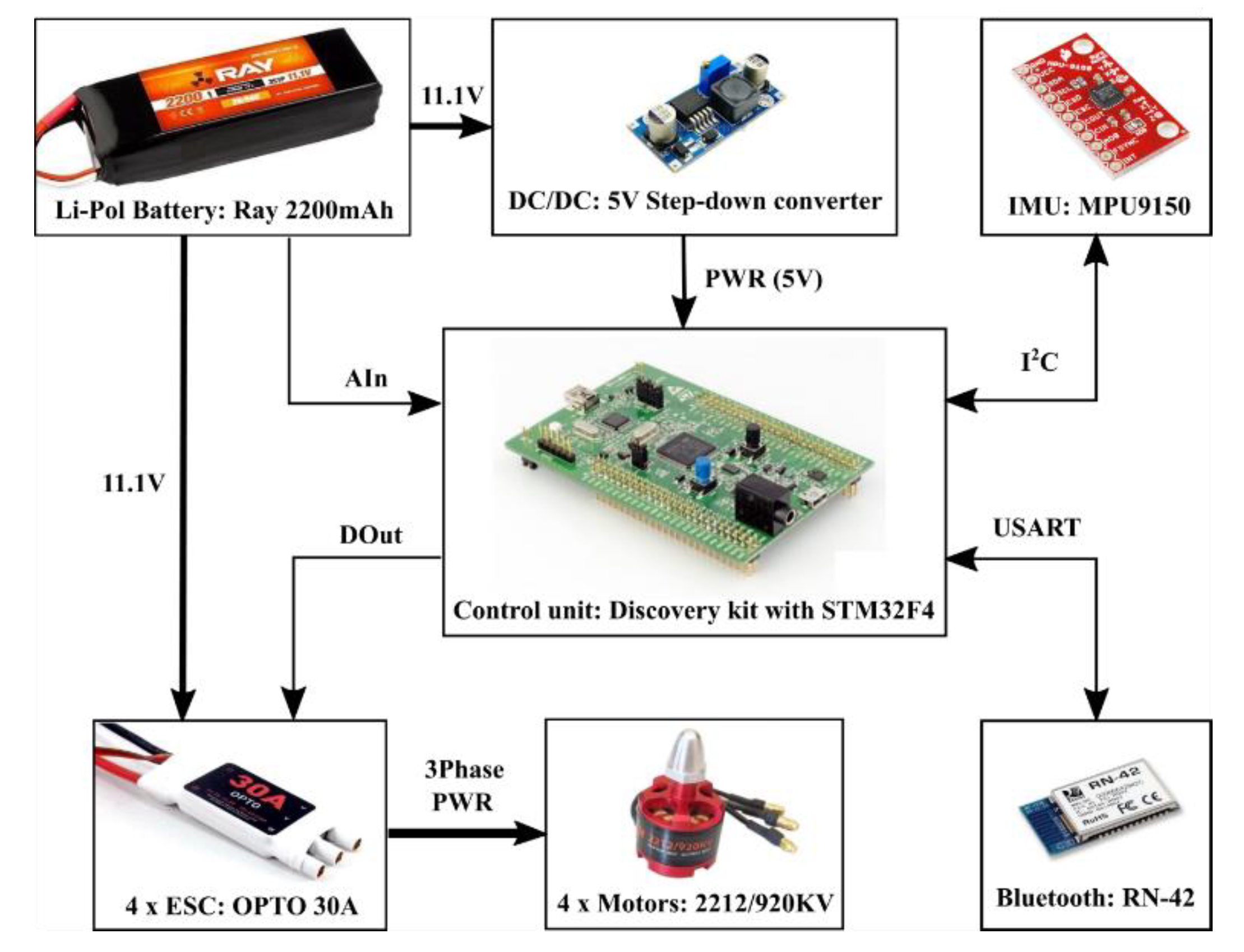
The chosen platform for the verification of control techniques was quadrotor DJI F450. The platform by DJI company consists of a main frame, 30A OPTO ESCs and 2212/920 KV motors. This class of motors was chosen because the total produced thrust of all four motors will be twice as much as final weight of the quadrotor (expected to be around 1000 g). The voltage and type of propellers for these motors are recommended by the manufacturer. As power source, the LiPo battery pack was chosen because of its good weight to power ratio. Manufacturer of BLDC motor advise to use 3 or 4 LiPo cells. With 3 LiPo cells, the 2212/920 KV motor was powered with nominal voltage of 11.1 V. Its maximum rotation speed is about 10,000 rpm. Recommended propeller 10” × 45” with 25.4 cm in diameter lowers this rotation speed to about 7000 rpm with maximum thrust about 800 g. Motor manufacturers usually mention maximum current consumption at this rotational speed, in this case around 10 A. When this value is multiplied by 4, maximum current consumption of the flying platform can be estimated. Current consumption of other electronics could be in this case neglected. With calculated maximum current battery with higher current loading and capacity to maintain required flying time can be chosen. Battery with capacity of 2.2 Ah was chosen, which provides hover time of about 5 min. The battery has 26C current loading, which is about 57 A, and it was enough for evaluation of the proposed controllers. Maximum current consumed by motor also determines the selection of ESC. A 30 A ESC with 30 to 450 Hz frequency response was chosen, which enables to refresh rotation speed of motor more often than conventional 50 Hz ESCs.
Figure 7 shows all abovementioned components and their interconnections. The control unit should maintain control, mathematical and other important operations. There are many usable development platforms, but something more powerful than the standard ARDUINO platform and more real-time than the Raspberry Pi platform with a basic operating system was needed. Therefore, the Discovery platform with powerful microcontroller ST32F4 was chosen. This platform runs at 168 MHz rate, it is relatively cheap, easy to program and offers lots of analogue and digital IO pins and communication interfaces as USART, SPI, I2C and so on. The control unit was powered by the LiPo battery via 5 V step-down converter, that transforms battery voltage to necessary voltage of 5 V. The battery is also connected to the ESCs to power all motors. In order to avoid damage to the battery due to an over-discharge, the analogue input (AIn) was wired to read the actual value of the voltage of connected battery. The IMU MPU9150 was used to measure angular speed in the body-fixed frame. The IMU is able to measure all angular speeds and linear acceleration every 1 ms. The orientation from magnetometer is possible to read every 7 ms. The I2C serial bus is used for communication between the control unit and the IMU. Several commercial IMU chips were compared in parameters as noise rejection, low gyroscope drift, measurement ranges, resolution, refresh, etc., and finally the mentioned MPU9150 unit was chosen. The Bluetooth device RN-42 was used to exchange data between the control unit and an external device such as computer. Module RN-42 offers high-speed full-duplex wireless communication link between PC and STM32F4 on the control board. The USART (Universal Synchronous/Asynchronous Receiver and Transmitter) was used to exchange data between the Bluetooth device and the control unit. The ESCs acquires PWM from the digital outputs (DOut) of the control unit, and transforms this signal into 3-phase power waveform that makes the motor rotate at a specific angular speed.

3.2. The Software

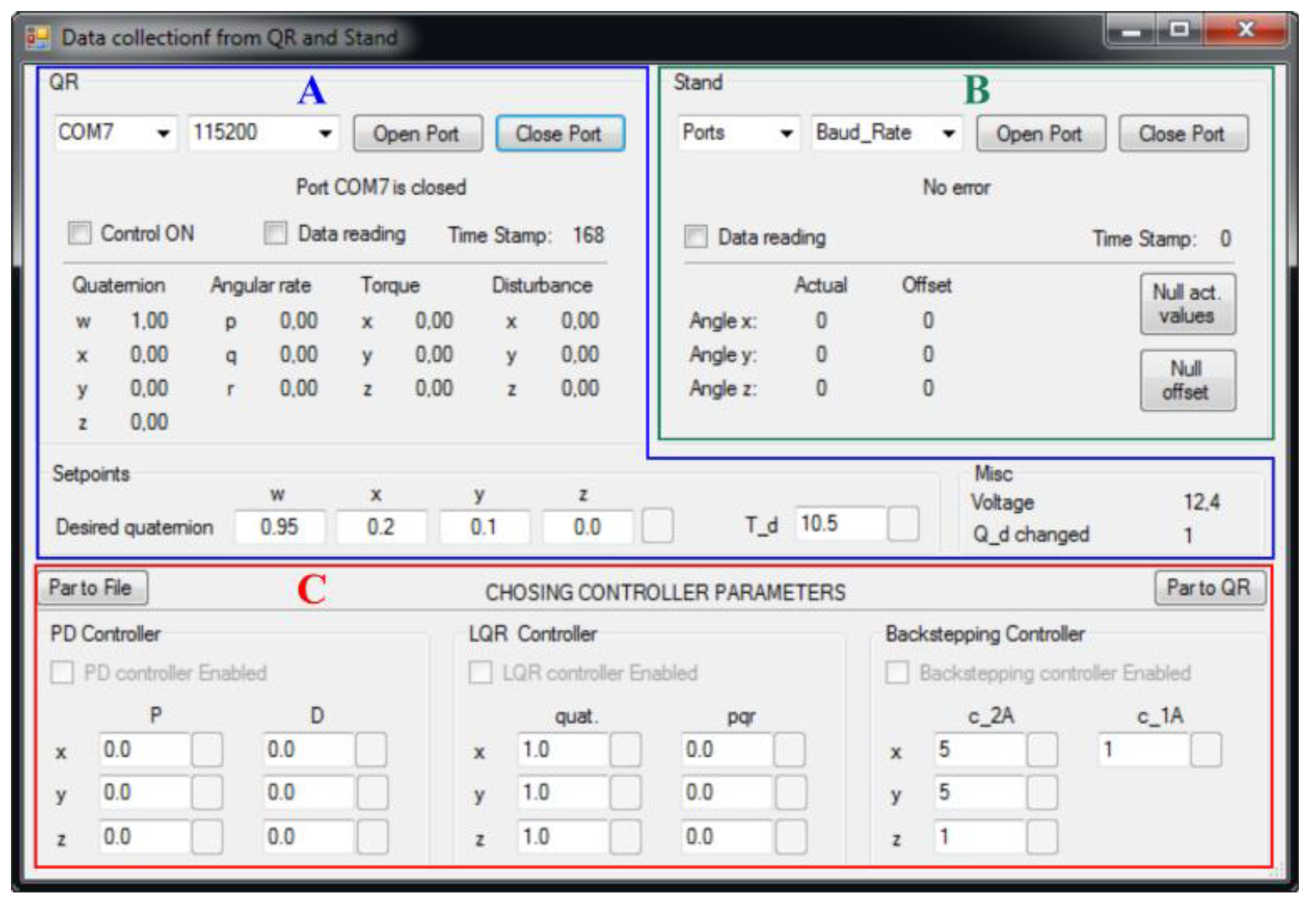
An application shown in Figure 8 was created using C# language and it serves as the interface between operator and the flying platform (Figure 8 Section A). This application also performs the function of being the interface to the test stand used to verify the proposed control algorithms (Figure 8 Section B). This application was also used to tune all designed attitude controllers (Figure 8 Section C). The main purpose of the application is to control and monitor the behavior of the real platform. The application is divided into two parts, namely the part dedicated to the real platform and the part dedicated to the test stand. The following commands can be sent to the real platform if the connection is established:
  • To enable/disable motors via checkbox “Control ON”.
  • To enable/disable logging data via checkbox “Data reading”.
  • To define the desired quaternion.
  • To define the desired thrust that is used to compute desired torques of the quadrotor.
  • To select one of the three controller types, namely PD, LQR and backstepping controller via corresponding checkboxes (i.e., “PD controller Enabled”, “LQR controller Enabled” and “Backstepping controller Enabled”).
  • To change each parameter of selected type of the controller several buttons are used that are located next to writable textboxes. If all parameters of the selected controller should be sent to real platform then the “Par to QR” button should be used.
When the connection to the real platform is established and the data logging is enabled, the following variables are obtained via Bluetooth from the real platform:
  • Actual quaternion
  • Actual angular rate of the quadrotor [rad·s−1]
  • Calculated desired torque [N·m]
  • Torque identified via attitude disturbance observer (DO) [N·m]
  • Actual voltage of the LiPo battery [V]
  • Single bit that monitors the change of the desired quaternion.
The application is updated every 500 ms, while the change of every parameter is logged each 10 ms and it is recorded into the text file “QR_data.txt”. Furthermore, the application contains the button “Par to File” that is used to store actual parameters of the all controllers to the text file “Control_param.txt”. If this file exists during the start of the application, the last-stored controller values are used to automatically prefill controller parameters. The part dedicated to the test is used to establish and terminate connection between the test stand and a computer. Further, there is checkbox “Data reading” used to start reading and logging data from the test stand to the text file “Stand_data.txt”. The data monitored from the test stand are all Euler angles that are displayed every 100 ms but, as in the previous case, the data is logged with finer sampling (i.e., every 10 ms).
Because the test stand is equipped with absolute rotary sensors, the option to calculate offset was added to the application via button “Null act. values”. The corresponding offset is displayed next to recalculated actual values of Euler angles. The offset can be reset any time using the button “Null offset”.

3.3. Tuning of Controllers

The controller parameters derived in our previous work [9] had to be newly tuned because the quadrotor showed unstable behavior. This was caused because the dynamics of the test stand and its lack of rigidness had considerable impact on the quadrotor performance. Moreover, some parameters used in the mathematical model was not accurately computed. The example of such parameters can be the motor constants, because bearings of the motors are probably worn in the moment of the data reading. In addition, the dynamics only of one motor were identified. Further when the identification was made only with one motor connected to the battery at that time, this was completely different situation compared to four motors connected. Therefore, the used battery cannot supply stable power to all motors.
The implemented attitude controllers were evaluated by tracking desired sequence of orientation. Parameters for each axis were tuned separately. The first tuned parameters were parameters related to z axis, followed by the parameters of x axis. The last tuned parameters were those of y axis.
Firstly, proportional parameters of the PD controller were identified. The derivative parameter was set to 0 and the proportional part of the controller was increased step by step until the quadrotor starts to oscillate around the particular axis. Then the 80% of the value was set to be the proportional part of the PD controller. The derivative part of the PD controller was increased until the settling time of the quadrotor was around 1–2 s. Table 3 shows the list of the chosen corresponding gains for proportional and derivative components of the attitude PD controller.
The LQR controller was tuned in the similar way as the PD controller. Firstly, the elements of gain matrix KA that correspond to the quaternion were tuned. Subsequently, the elements of the gain matrix KA corresponding to angular velocity of the quadrotor were identified. The regulator gain matrix KA of LQR controller is given by equation:
K A = [ 1.34 0 0 0.3 0 0 0 1.34 0 0 0.3 0 0 0 0.6 0 0 0.3 ]
The parameters of the backstepping controller were tuned as followed: The value of the parameter c1A is 10 and c2A is a diagonal matrix with vector [ 11 11 3 ] on the main diagonal. The parameters of backstepping controllers were obtained in the similar way as the parameters of the PD and LQR controller. That means the first tuned parameter was c1A, which corresponds to the attitude of the system. Then the vector c2A related to angular velocity of quadrotor was identified.

3.4. Evaluation of Controllers

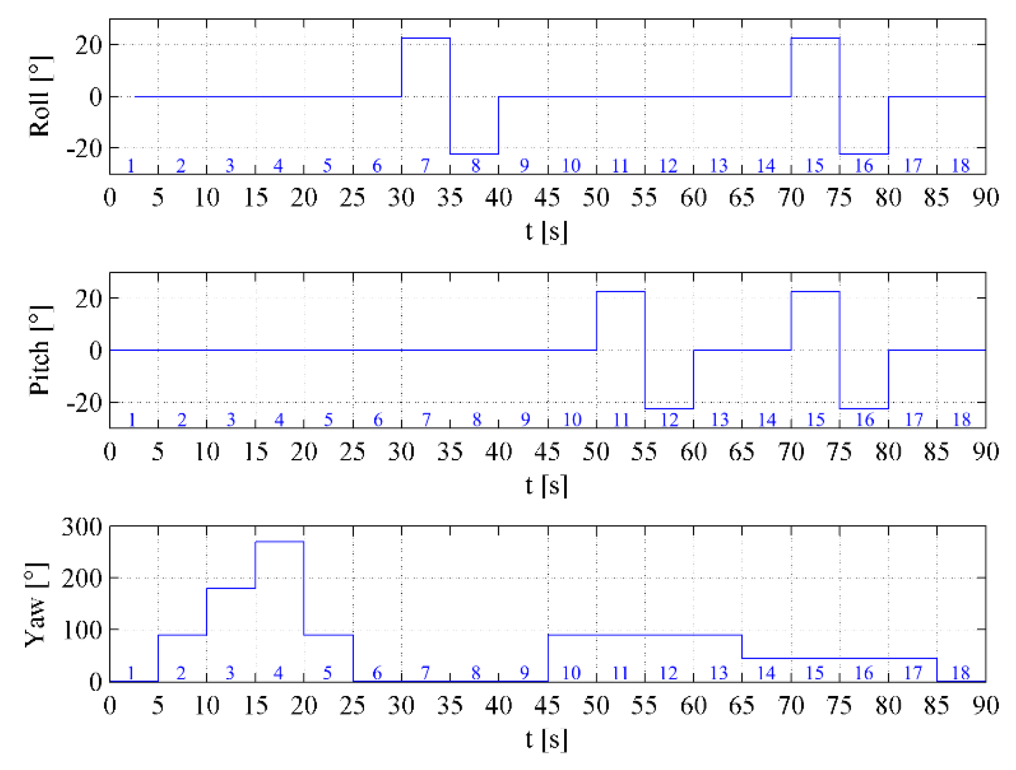
Firstly, the desired sequence of the required setpoints of the orientation will be outlined. Secondly the performance of all controllers will be evaluated. Finally, some of quality indicators will be used to make comparison between implemented control techniques.

3.4.1. The Sequence of Required Setpoints

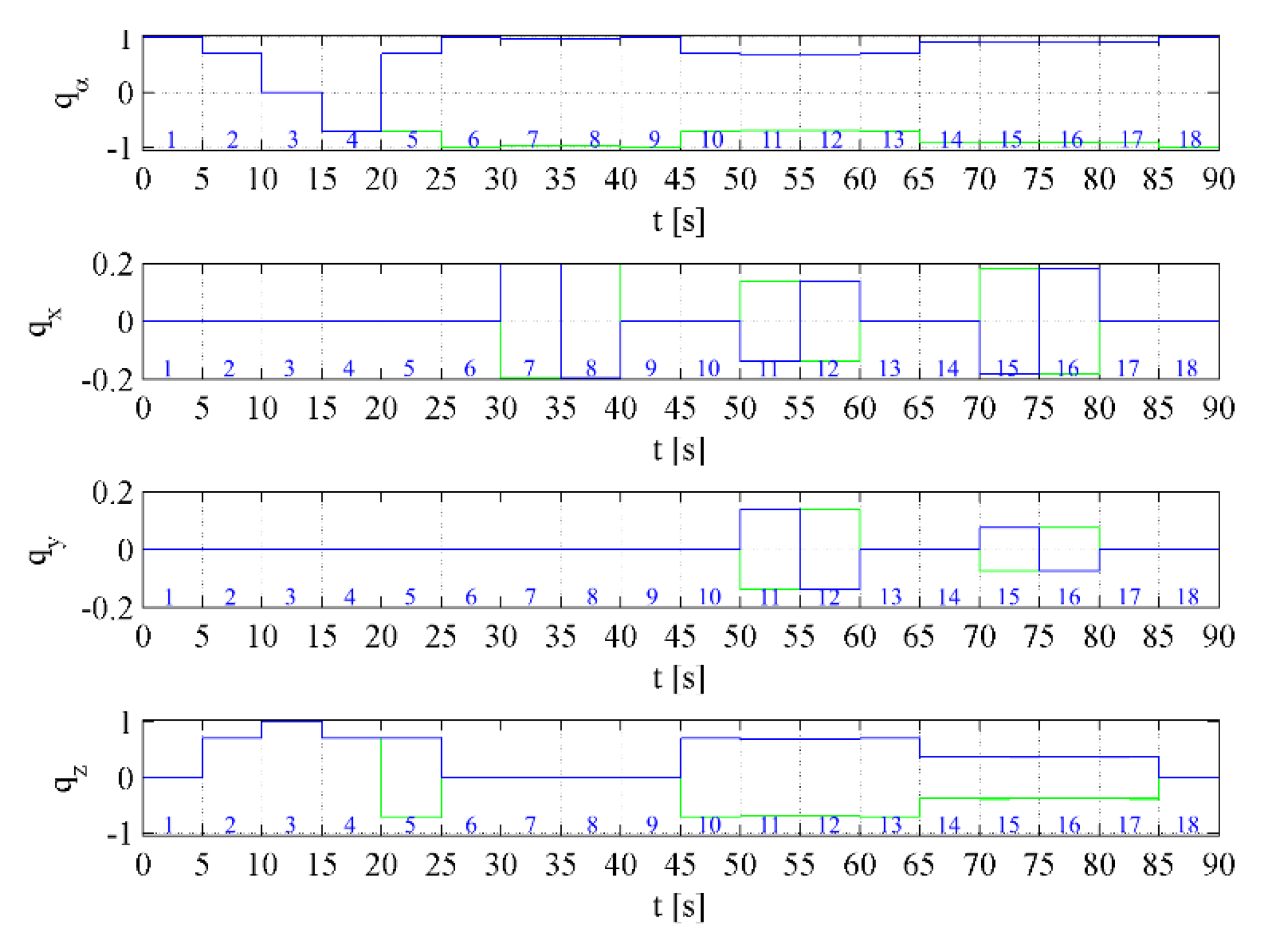
The sequence of required setpoints using Euler angles representation of orientation is shown in Figure 9. Quaternion representation of the same sequence is shown in in Figure 10. The sequence is divided into 18 sections, which is also the number of setpoints in the sequence.
Quaternion represents the rotation of the object with the respect to initial orientation. The rotation can be executed in two ways (i.e., clockwise rotation or counter-clockwise rotation). The rotation of 360° around any axis is represented by the following quaternion q = [ 1 0 0 0 ] . Because of abovementioned reasons, Figure 10 contains two sequences (blue and green line) representing the same orientation of the quadrotor. The point of sequence parting is when quadrotor is ordered to rotate back from the rotation of 180° around z axis. The direction of the rotation from this orientation depends on the variation of the setpoint orientation, because the quadrotor will rotate in the direction that requires smaller rotation.
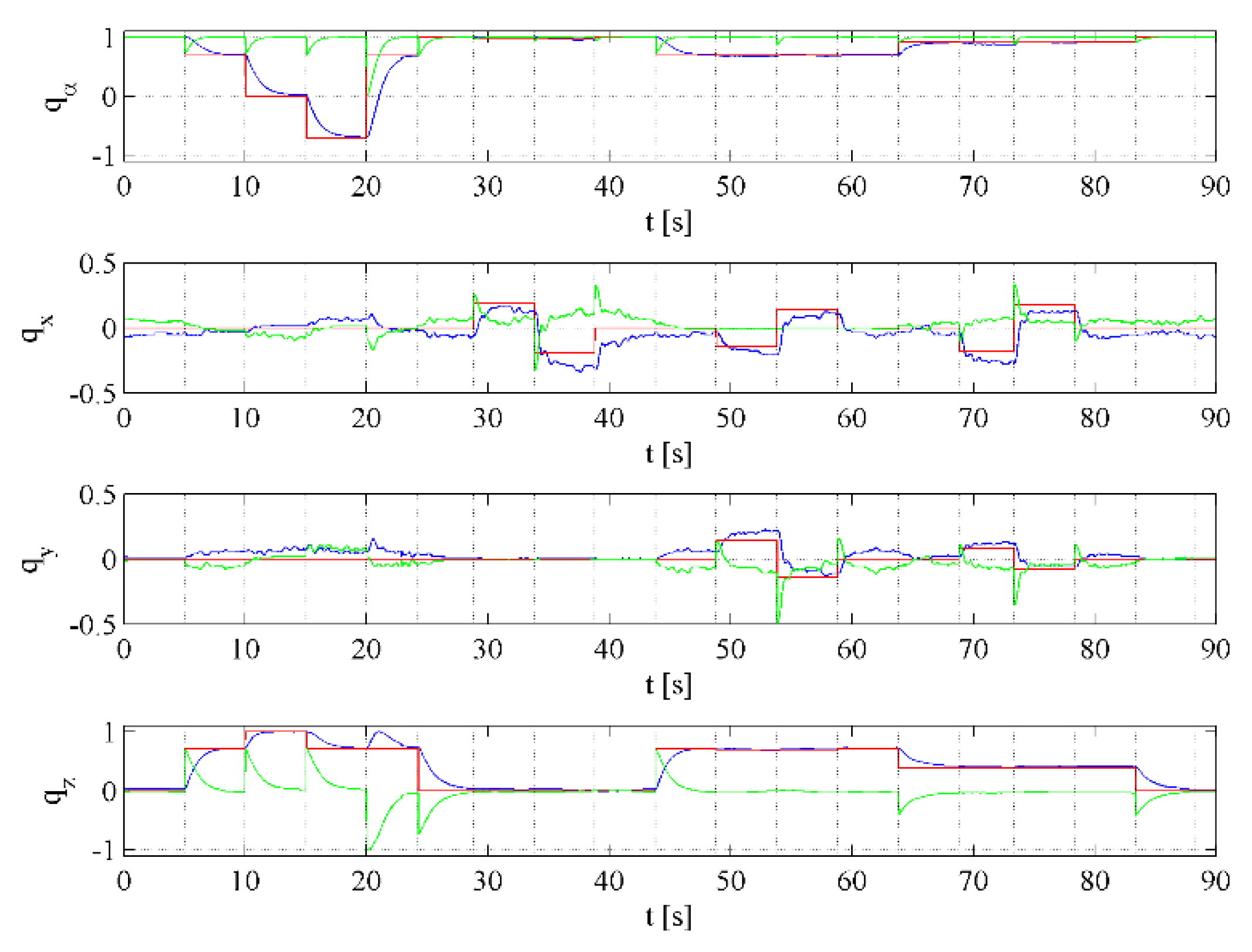
The performances of designed controllers (i.e., PD, LQR and backstepping controller) are outlined in the following figures: Figures 11, 14 and 17, respectively. Figures show the actual quaternion represented by blue line, quaternion error represented by green line and the desired quaternion represented by red and magenta line. Change in setpoint around z axis also influences the rest of the axes. This is given by the computation of the quaternion error. The change in the orientation around z axis causes also the changes of the quaternion error in the remaining axes.

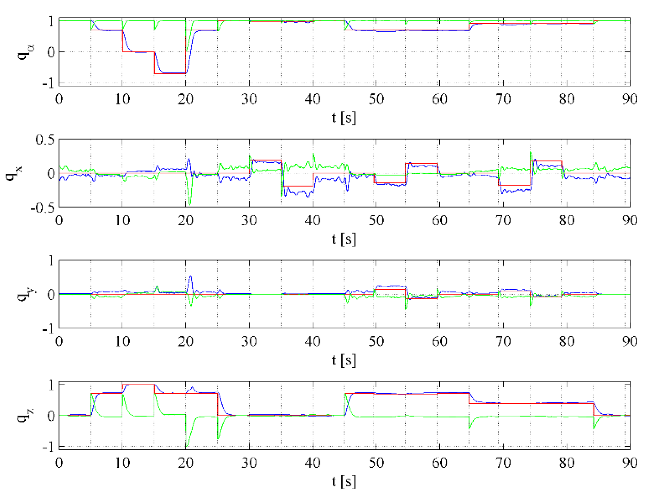
3.4.2. PD Controller

The performance of the PD attitude controller is shown in the following figures: Figure 11, Figure 12 and Figure 13.
Figure 11 highlights the change of the orientation of the quadrotor during the performance of the desired sequence (Section 3.4.1). The trajectory around z axis coincides with the desired trajectory, but the trajectory around x and y axis shows the permanent deviation and oscillation. This behavior is caused by the lack of the rigidness of the test stand in both x and y axis. The rotation in both problematic axes is provided by carbon tubes of almost 1 m length. Moreover, the ends of the tubes are flexible. Therefore, the performance of the controller is affected by the mechanical oscillation of the designed test stand. The movement in z axis is not affected because rotation point around z axis of the test stand coincides with the rotation point of the quadrotor.
The settling time of the desired orientation in x and y axis is mostly less than 1 s when permanent deviation is neglected. The slower dynamics of the z axis is required because the control of the orientation around this axis has lower importance.
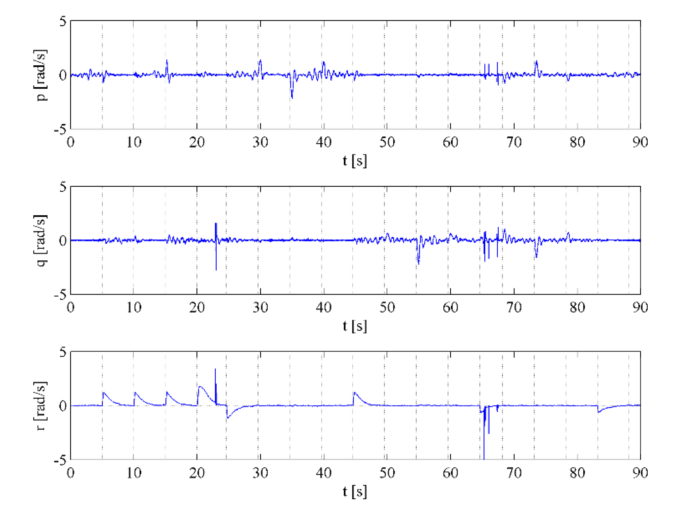
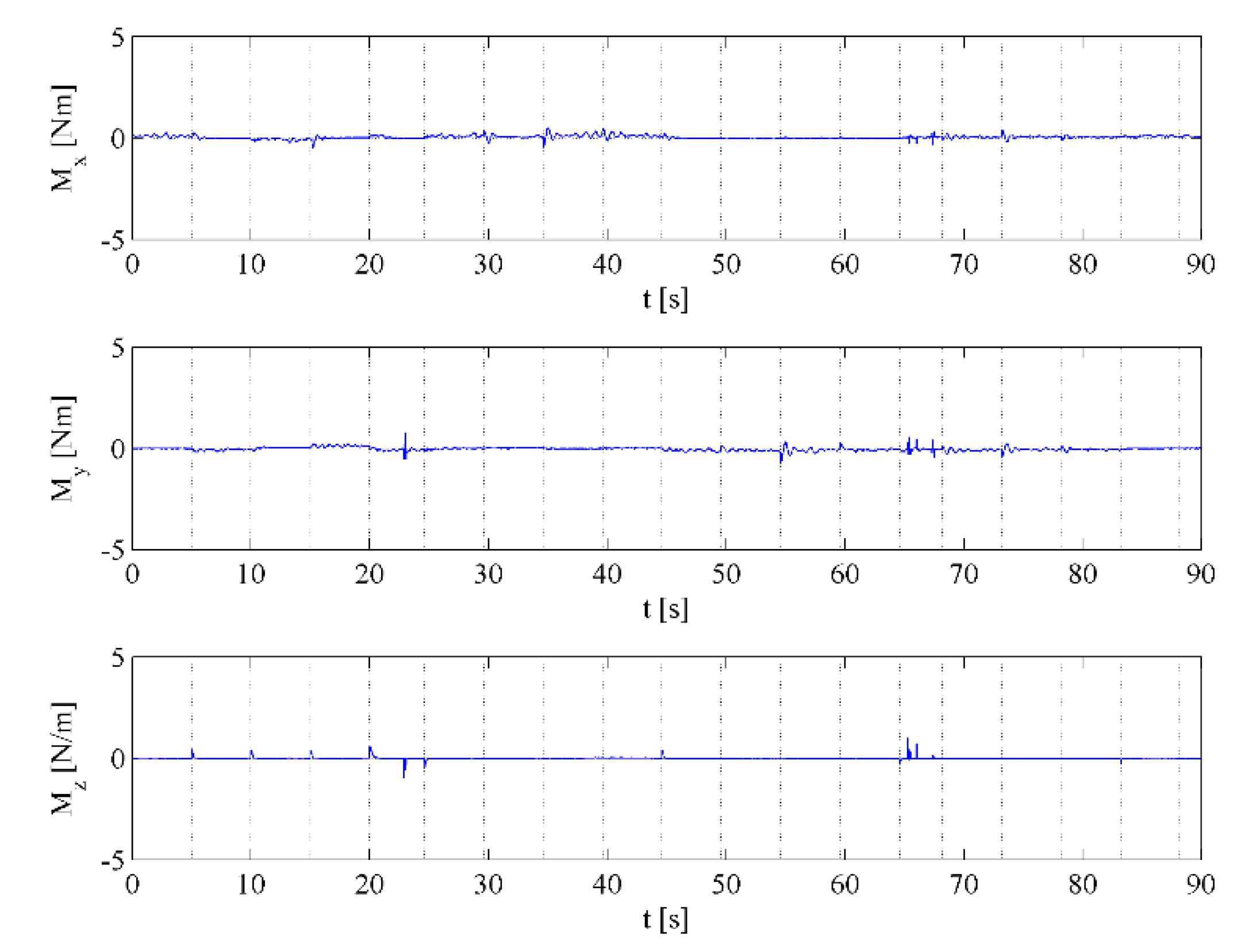
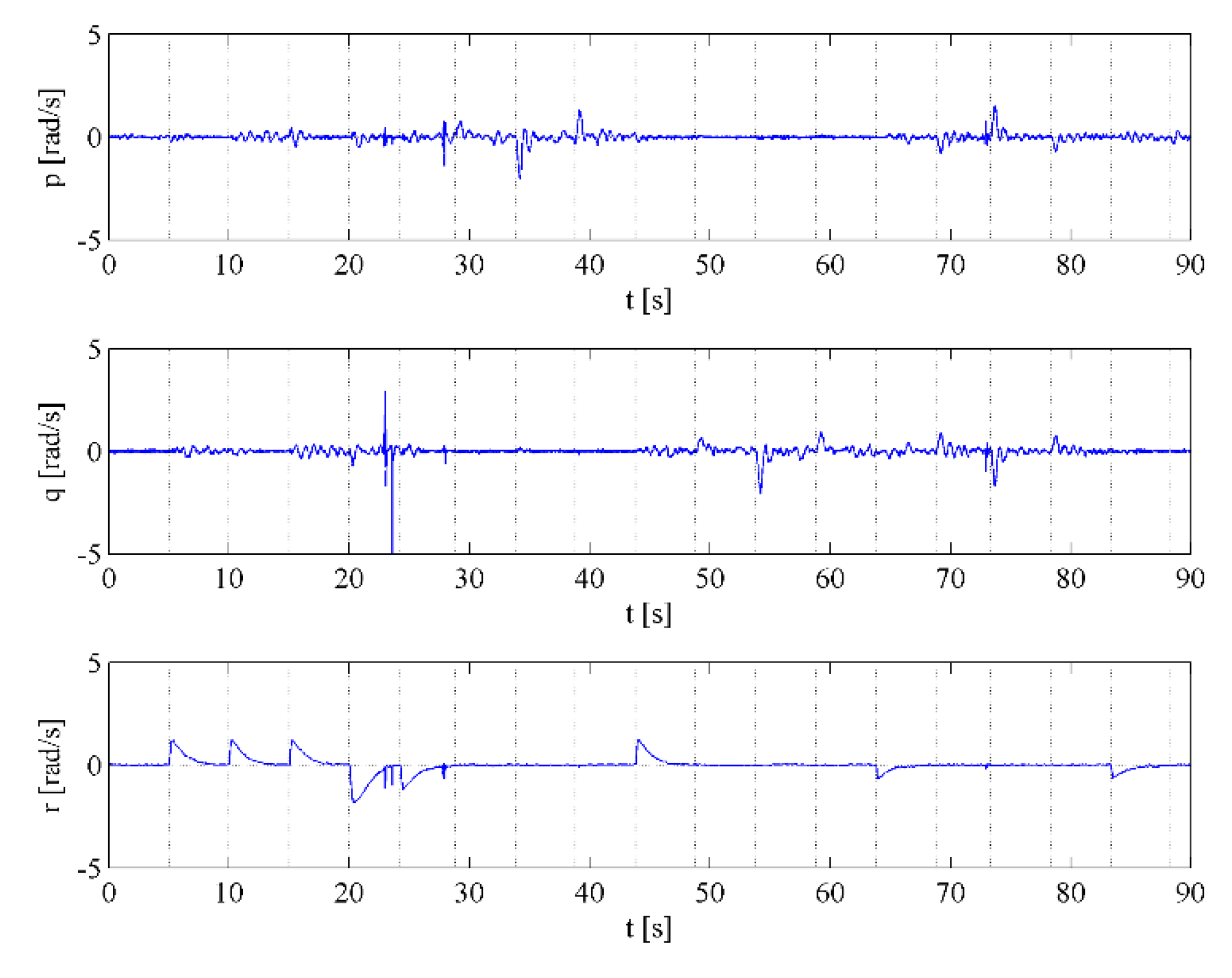
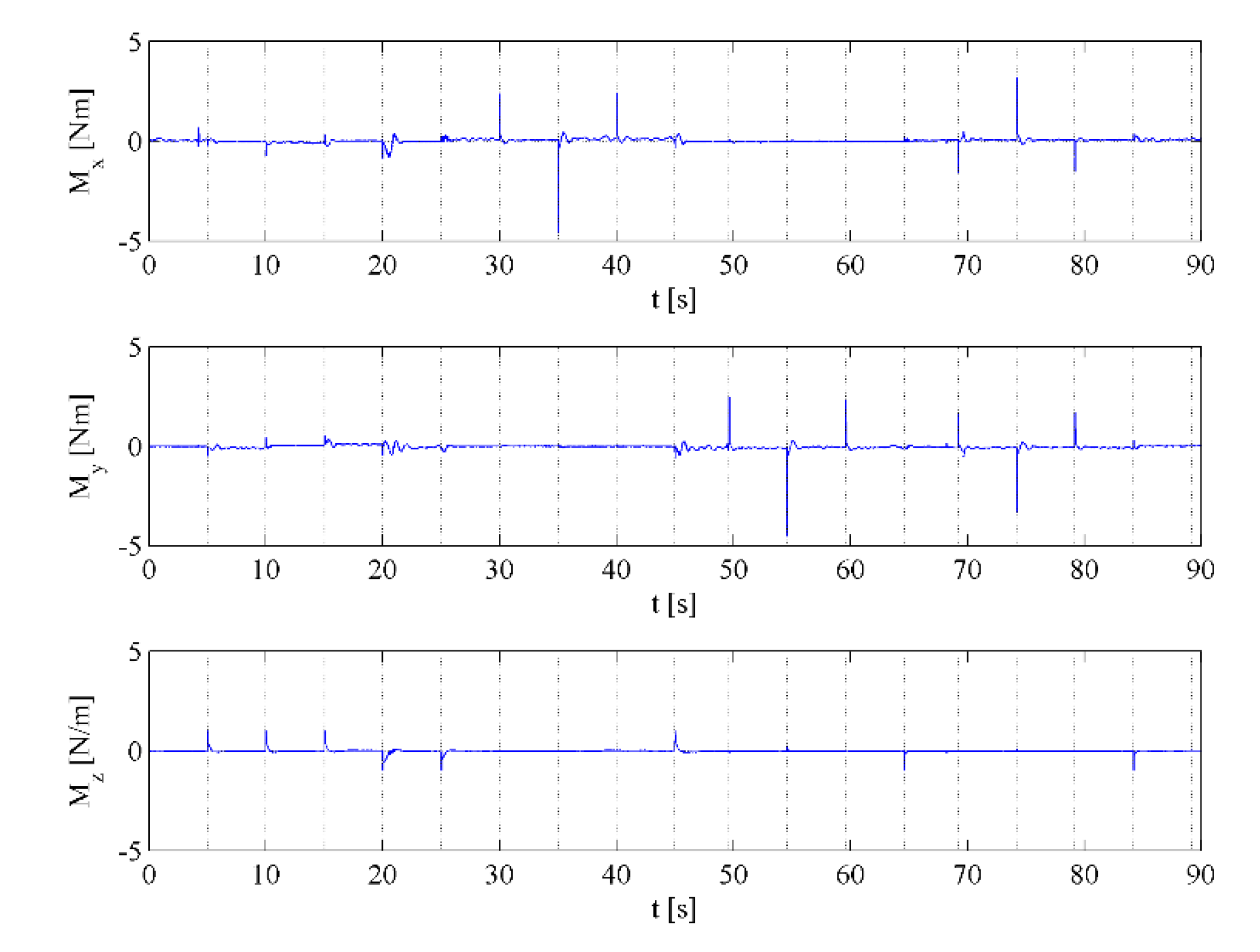
Figure 12 shows the actual angular velocity in EB (the body-fixed frame) of the quadrotor that belongs to the performance of PD attitude controller. The angular velocity r is smooth in contrast with the oscillation of angular velocity p and q. This oscillation is caused by the oscillation of the desired torque around abovementioned axes depicted in Figure 13.

3.4.3. LQR Controller

The performance of the LQR attitude controller is shown in the following figures: Figure 14, Figure 15 and Figure 16.
Figure 14 highlights the change of the orientation of the quadrotor during the performance of the desired sequence (Section 3.4.1). The trajectory around z axis coincides with the desired trajectory, but the trajectory around the x and y axes shows the permanent deviation and oscillation. The cause of these phenomes is the non-rigidness of the test stand. This was explained in a previous subsection when evaluating the performance of PD controller.
The settling time of the desired orientation in the x and y axes is mostly less than 1 s when permanent deviation is neglected. The slower performance of the z axis is required because of the lower importance of control around this axis.
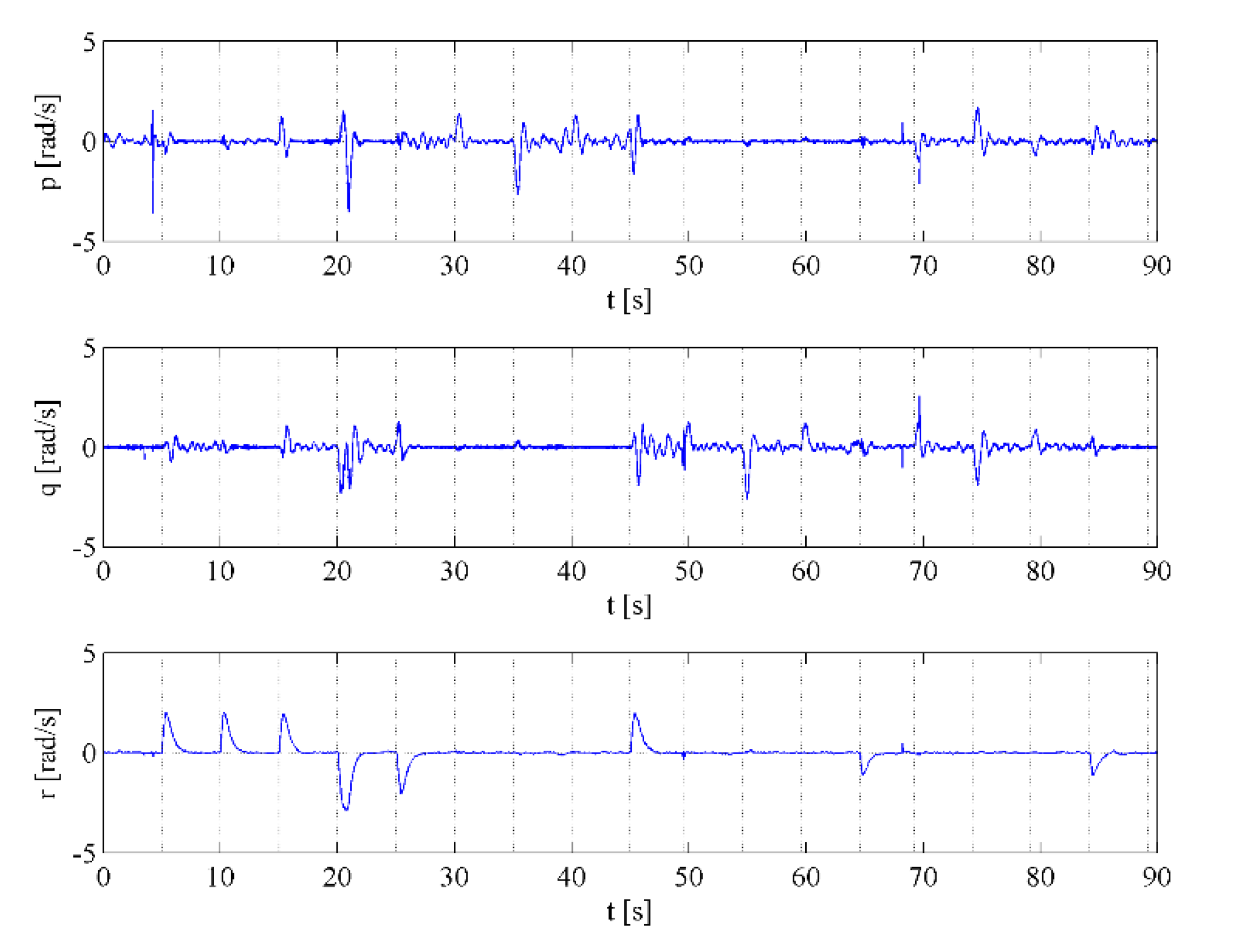
Figure 15 depicts the actual angular velocity in EB of the quadrotor that belongs to the performance of LQR attitude controller. The angular velocity r is smooth in contrast with the oscillation of angular velocity p and q. This oscillation is caused by the oscillation of the desired torque around abovementioned axes depicted in Figure 16.

3.4.4. Backstepping Controller

The performance of the backstepping attitude controller is shown in the following figures: Figure 17, Figure 18 and Figure 19.
Figure 17 highlights the change of the orientation of the quadrotor during the performance of the desired sequence (Section 3.4.1). The trajectory around z axis coincides with the desired trajectory, but the trajectory around the x and y axes suffers from the permanent deviation and oscillation. The cause of this phenomenon is the non-rigidness of the test stand. This effect was explained in previous subsections. Performances of all implemented controllers contain very similar oscillation and deviation around the x and y axes, which supports presented theory about the source of the oscillation and also deviation.
The settling time of the desired orientation in the x and y axes is mostly less than 1 s when permanent deviation is neglected. The slower performance of the z axis is required because of the lower importance of control around this axis.
Figure 18 shows the actual angular velocity in EB (the body-fixed frame) of the quadrotor that belongs to the performance of backstepping attitude controller. The angular velocity r is smooth in contrast with the oscillation of angular velocity p and q. This oscillation is caused by the oscillation of the desired torque around abovementioned axes depicted in Figure 19.

3.4.5. Controllers Comparison

Various quality indicators were chosen to discuss the efficiency of the control algorithms, such as the integral of absolute error IAE, integral of absolute desired torque IAM and maximum absolute variation of the quaternion Oq.
The performance of all attitude controllers is summarized in tables that can be found in Appendix A. Chosen quality indicators are identified separately for each section of the desired sequence. Table 4 shows the total number of the best and also the worst performances related to the particular quality indicator. The best value of each quality indicator for entire sequence is indicated by green color and the worst value is indicated by red color.
The evaluation of the performed sequences of chosen controllers can be done in two different ways.
The first approach is focused mainly on the reaching the desired orientation in the shortest possible time omitting the importance of the efficiency of power supply. The integral of total absolute quaternion error and the maximal absolute quaternion variation are decisive quality indicators used in this approach. The backstepping controller indicates the smallest value of the sum of all parts of the quaternion error and it also shows the best control around z axis. However, when it comes to control around the x and y axes this controller exhibits the worst results. The best attitude control around the x and y axes was achieved by LQR controller. The PD controller shows average performance when only the integral of total absolute quaternion error and maximal absolute quaternion variation as quality indicators is considered. To sum up, the LQR attitude controller is considered to be the best option when taking into account only the importance of reaching the desired quaternion as fast as possible.
The second approach is focused not only on reaching the desired orientation, but it also takes into account the efficiency of the power supply. The second approach expands the quality indicators from the first approach with the total absolute desired torque. The most energy efficient controller was the LQR controller, which consumed the least energy during the whole sequence. When the movement is divided into various rotations related to the particular axis, the LQR controller is the most efficient controller around the x and y axes, while around z axis the most efficient controller is the PD controller. The backstepping controller consumes the most from power supply among implemented controllers. When taking into account the energy consumption and also the quaternion error, the best performance exhibits the LQR controller and the worst performance shows the backstepping controller. As in the previous case, the PD controller exhibits average performance.
As it can be seen in Table 4, the best performance with respect to chosen quality indicators is exhibited by the LQR controller. The worst performance with respect to chosen quality indicators is demonstrated by the backstepping controller. The PD controller shows average performance.

4. Conclusions

In this article, different control techniques were implemented into the real quadrotor, namely the PD, the LQR and the backstepping control techniques. All controllers used the quaternion representation of the attitude. The output of position controllers is the desired quaternion and the desired thrust of quadrotor. The controllers were designed to use calculated quaternion error for the computation of the desired torques. In our previous work [35], the designed attitude controllers were tested in simulation environment. In this article the selected controllers were tested and evaluated on the real quadrotor. These controllers were verified using the innovative test stand, which was designed especially for this purpose. Appropriate test stand properties (safety and orientation measuring) were confirmed by several measurements. However, the measurements were influenced not only with additional moment of inertia but with the oscillations caused by low rigidness of used materials. The performance of controllers was evaluated using various quality indicators, such as the integral of absolute quaternion error, integral of absolute desired torque and the maximal absolute variation of the quaternion.
The best performance with respect to chosen quality indicators was shown by the LQR controller. The worst performance with respect to chosen quality indicators was demonstrated by the backstepping controller. The limitation of this study is that only three selected controllers were evaluated. As it was mentioned in the Section 3.3, the parameters of the real quadrotor were slightly different from the ones identified in our previous work. Therefore, the selected three controllers from the simulations may not have been the best. However, the suitability of creating a new stand for quadrotor testing as well as a comprehensive evaluation methodology was demonstrated.

5. Patents

CHOVANCOVÁ, Anežka-FICO, Tomáš. Zariadenie na testovanie VTOL platforiem: Úžitkový vzor č. 7766, Dátum o zápise ÚV: 24.3.2017, Vestník ÚPV SR č. 5/2017. Banská Bystrica: Úrad priemyselného vlastníctva SR, 2017. 12 s.

Author Contributions

A.C. was the main investigator of the results. T.F. was the main developer of the software. F.D. has wrote the original text. M.D. (Martin Dekan) was responsible for generating all the graphs. Ľ.C. contributed to the testing and visualization of the components. M.D. (Martin Dekanová) is responsible for reviewing and editing the text. All authors have read and agree to the published version of the manuscript.

Funding

This research was funded by VEGA grant number 1/0752/17 and APVV grant number APVV-16-0006.

Acknowledgments

This work was supported by VEGA 1/0752/17 and APVV-16-0006.

Conflicts of Interest

The authors declare no conflict of interest.

Appendix A

Various quality indicators were chosen to discuss the good working ability and the efficiency of the proposed algorithms, such as the integral of absolute error IAE, integral of absolute desired torque IAM and maximum overshoots Oq.
The performance of all attitude controllers is summarized in the following tables, where integral of total absolute quaternion error and total absolute desired torque is reported in Table A1. Table A2 and Table A3 list integral of absolute quaternion error. Table A4 and Table A5 show integral of absolute desired torque. Table A6 and Table A7 list maximal absolute quaternion variation.
The best value of each quality indicator is indicated by green color and the worst value is indicated by red color.
Table A1. Quality indicators of controllers’ performance: Integral of total absolute errors and total absolute desired torque produced during sequence (PD—PD controller, LQR—LQR controller, BC—backstepping controller).
PDLQRBS
IAE1950.631923.931843.39
IAM [N·m·s]1453.241396.231635.40
Table A2. Quality indicators of controllers’ performance: Integral of scalar part of absolute quaternion error IAEA and the vector part of the absolute quaternion error related to x axis IAEx (PD—PD controller, LQR—LQR controller, BS—backstepping controller).
Part of SequenceIAEAIAEx
PDLQRBSPDLQRBS
10.521.873.2676.9778.35125.42
218.4917.1912.8310.038.2811.32
317.5617.410.4426.2032.3330.84
420.0720.8813.708.346.669.60
586.4583.3365.0516.3621.0238.53
622.1823.0517.9736.4625.1240.59
71.411.680.8833.8838.2925.51
83.172.663.3861.3550.1554.93
94.363.602.6060.8854.1652.50
1018.5617.4115.437.056.1813.30
110.351.372.6411.994.6414.30
125.685.002.963.210.423.93
130.380.700.977.802.057.30
145.105.854.129.2811.7613.05
151.381.612.6620.1625.8329.01
163.924.433.8538.1335.534.45
170.170.412.1716.3824.425.97
186.426.574.4134.8620.732.37
Total216.19215.01170.64494.79471.82595.9
Table A3. Quality indicators of controllers’ performance: Integral of the vector part of absolute quaternion error related to y axis IAEy and z axis IAEz (PD—PD controller, LQR—LQR controller, BS—backstepping controller).
Part of SequenceIAEyIAEz
PDLQRBSPDLQRBS
110.1514.9522.4213.8330.5632.34
234.5729.3639.9076.8675.2156.41
39.088.0612.3778.8380.4845.23
444.6141.1339.3879.3387.5353.97
531.5816.5239.77161.51164.32106.8.
69.578.3211.4396.3699.3658.32
72.614.990.5111.699.3110.61
88.514.478.476.067.328.56
90.550.175.006.034.253.99
1038.1636.7041.8375.6073.3759.25
1135.9237.1942.8310.3910.2519.04
1261.8553.4536.3411.026.9814.75
1328.6736.3232.7120.1410.0821.68
1418.0014.9119.4041.7459.8341.05
1535.3028.2138.8215.7215.0213.44
1639.9236.5235.9114.0013.0513.07
1723.2424.5931.3315.1915.3219.38
186.892.483.1550.0457.6433.56
Total443.64403.03461.57796.01834.07615.28
Table A4. Quality indicators of controllers’ performance: Integral of absolute desired torque around x axis (IAMx) and y axis (IAMy) (PD—PD controller, LQR—LQR controller, BS—backstepping controller).
Part of SequenceIAMxIAMy
PD [N·m·s]LQR [N·m·s]BS [N·m·s]PD [N·m·s]LQR [N·m·s]BS [N·m·s]
1102.01103.25146.7618.3929.2031.52
216.8113.0817.3342.4338.7549.96
333.5743.5436.3714.5312.0516.46
420.4816.0017.9657.2453.0145.79
521.1625.1556.8140.4039.5557.78
648.7034.7647.2914.9712.9616.54
739.6238.3531.786.645.674.49
880.5379.2274.7312.266.5910.62
968.5357.2559.694.114.466.45
1013.1310.7424.0451.8248.1857.89
1117.607.8317.9754.3355.3956.06
126.174.675.4165.5154.1446.65
1311.035.109.3039.7251.2444.81
1414.5519.2817.8828.3625.3524.17
1530.7610.3437.6852.6644.9050.54
1642.0136.6643.2444.9738.4445.52
1724.7635.3934.6434.7136.1241.53
1845.1628.4940.459.116.268.15
Total668.45632.33758.78598.52568.45617.36
Table A5. Quality indicators of controllers’ performance: Integral of absolute desired torque around z axis (IAMz) (PD—PD controller, LQR—LQR controller, BS—backstepping controller).
Part of SequenceIAMz
PD [N·m·s]LQR [N·m·s]BS [N·m·s]
18.7226.1316.03
214.3214.6823.39
39.187.6815.79
49.398.3216.63
522.7116.6336.71
611.8112.6515.73
76.355.807.29
85.24.296.19
94.154.923.01
1014.2914.0625.25
115.035.6111.06
128.746.7711.60
1312.236.0913.99
1412.4512.9413.30
158.459.208.04
169.177.409.19
178.419.5013.00
186.789.798.80
Total186.26195.45259.27
Table A6. Quality indicators of controllers’ performance: Maximal absolute variation of scalar part of quaternion OQA and the vector part of the quaternion related to x axis OQx (PD—PD controller, LQR—LQR controller, BS—backstepping controller).
Part of SequenceOQAOQx
PDLQRBSPDLQRBS
10.010.010.010.120.110.15
20.020.020.040.130.060.12
3-0.010.020.030.030.05
4-0.010.010.090.080.11
50.280.030.030.130.030.21
6---0.120.080.14
70.010.02-0.020.050.01
80.040.040.050.150.150.17
9---0.070.040.05
100.020.020.050.030.070.27
110.02-0.050.050.070.05
120.020.020.030.040.030.01
130.040.010.040.040.080.01
140.010.010.010.060.060.07
150.040.040.050.090.100.13
160.03-0.010.050.040.02
170.010.010.010.060.090.09
18---0.090.060.15
Total0.550.250.411.371.231.81
Table A7. Quality indicators of controllers’ performance: Maximal absolute variation of the vector part of quaternion related to y axis (OQy) and z axis (OQz) (PD—PD controller, LQR—LQR controller, BS—backstepping controller).
Part of SequenceOQyOQz
PDLQRBSPDLQRBS
10.010.010.010.070.090.09
20.070.070.090.010.010.02
30.090.030.12---
40.150.110.220.01-0.01
50.070.150.54-0.290.01
60.060.040.130.020.03-
70.010.010.010.030.010.03
80.020.010.030.02-0.03
90.010.010.010.020.030.02
100.090.080.120.010.010.03
110.100.090.100.010.020.01
120.040.030.020.040.030.04
130.070.090.090.01-0.03
140.070.050.060.030.040.02
150.070.050.07-0.01-
160.020.020.010.030.020.03
170.040.040.050.040.040.05
180.040.01-0.010.010.01
Total1.030.91.680.360.640.43

References

  1. Tomić, T. Evaluation of acceleration-Based disturbance observation for multicopter control. In Proceedings of the ECC, Strasbourg, France, 24–27 June 2014; pp. 2937–2944. [Google Scholar]
  2. Alaimo, A.; Artale, V.; Milazzo, C.R.L.; Ricciardello, A. PID controller applied to hexacopter flight. J. Intell. Robot. Syst. 2013, 73, 261–270. [Google Scholar] [CrossRef]
  3. Honglei, A.; Jie, L.; Jian, W.; Jianwen, W.; Hongxu, M. Backstepping-Based inverse optimal attitude control of quadrotor. Int. J. Adv. Robot. Syst. 2013, 10, 223. [Google Scholar] [CrossRef]
  4. Siciliano, B.; Khatib, O. Springer Handbook of Robotics, 2nd ed.; Springer: Berlin/Heidelberg, Germany, 2016. [Google Scholar]
  5. Huo, X.; Huo, M.; Karimi, H.R. Attitude stabilization control of a quadrotor UAV by using backstepping approach. Math. Probl. Eng. 2014, 2014, 749803. [Google Scholar] [CrossRef]
  6. Cândido, A.S.; Galvão, R.K.H.; Yoneyama, T. Actuator fault diagnosis and control of a quadrotor. In Proceedings of the INDIN, Porto Alegre RS, Brazil, 27–30 July 2014; pp. 310–315. [Google Scholar]
  7. Lippiello, V.; Ruggiero, F.; Serra, D. Emergency landing for a quadrotor in case of a propeller failure: A PID based approach. In Proceedings of the SSRR, Lake Toya, Hokkaido, Japan, 27–30 October 2014; pp. 1–7. [Google Scholar]
  8. Lippiello, V.; Ruggiero, F.; Serra, D. Emergency landing for a quadrotor in case of a propeller failure: A backstepping approach. In Proceedings of the IROS, Chicago, IL, USA, 14–18 September 2014; pp. 4782–4788. [Google Scholar]
  9. Chovancová, A.; Fico, T.; Hubinský, P.; Duchoň, F. Comparison of various quaternion-Based control methods applied to quadrotor with disturbance observer and position estimator. Robot. Auton. Syst. 2016, 79, 87–98. [Google Scholar] [CrossRef]
  10. Shao, X.; Liu, J.; Cao, H.; Shen, C.; Wang, H. Robust dynamic surface trajectory tracking control for a quadrotor UAV via extended state observer. Int. J. Robust Nonlinear Control 2018, 28, 2700–2719. [Google Scholar] [CrossRef]
  11. Števek, J.; Fikar, M. Teaching aids for laboratory experiments with AR.Drone2 quadrotor. IFAC-PapersOnLine 2016, 49, 236–241. [Google Scholar] [CrossRef]
  12. Zhao, S.; Dong, W.; Farrell, J.A. Quaternion-Based trajectory tracking control of VTOL-UAVs using command filtered backstepping. In Proceedings of the ACC, Washington, DC, USA, 17–19 June 2013; pp. 1018–1023. [Google Scholar]
  13. Fresk, E.; Nikolakopoulos, G. Full quaternion based attitude control for a quadrotor. In Proceedings of the ECC, Zürich, Switzerland, 17–19 July 2013; pp. 3864–3869. [Google Scholar]
  14. Jadlovská, S.; Sarnovský, J. Nonlinear control design for inverted pendulum systems based on state-Dependent Riccati equation approach. In Proceedings of the International Conference on Applied Electrical Engineering and Informatics, Saarbrücken, Germany, 6–7 April 2012; pp. 22–26. [Google Scholar]
  15. Liu, Y.; Zhu, X.; Zhang, H.; Basin, M. Improved Robust Speed Tracking Controller Design for an Integrated Motor-Transmission Powertrain System over Controller Area Network. IEEE/ASME Trans. Mechatron. 2018, 23, 1404–1414. [Google Scholar] [CrossRef]
  16. Gabrlik, P.; Křiž, V.; Vomočil, J.; Žalud, L. The design and implementation of quadrotor UAV. Adv. Intell. Syst. Comput. 2014, 5, 47–56. [Google Scholar]
  17. Brahmi, B.; Saad, M.; Ochoa, C.; Luna, M.; Rahman, H.; Brahmi, A. Adaptive Tracking Control of an Exoskeleton robot with Uncertain Dynamics Based on Estimated Time Delay Control. IEEE/ASME Trans. Mechatron. 2018, 23, 575–585. [Google Scholar] [CrossRef]
  18. Wang, X.; Shirinzadeh, B.; Ang, M.H. Nonlinear double-Integral observer and application to quadrotor aircraft. IEEE Trans. Ind. Electron. 2015, 62, 1189–1200. [Google Scholar] [CrossRef]
  19. De Monte, P.; Lohmann, B. Trajectory tracking control for a quadrotor helicopter based on back stepping using a decoupling quaternion parametrization. In Proceedings of the 21st Mediterranean Conference on Control and Automation, Platanias-Chania, Greece, 25–28 June 2013; pp. 507–512. [Google Scholar]
  20. Bouhired, S.; Bouchoucha, M.; Tadjine, M. Quaternion-Based global attitude tracking controller for a quadrotor UAV. In Proceedings of the ICSC, Algiers, Algeria, 29–31 Octcber 2013; pp. 933–938. [Google Scholar]
  21. Madani, T.; Benallegue, A. Backstepping control for a quadrotor helicopter. In Proceedings of the IEEE/RSJ International Conference on Intelligent Robots and Systems, Beijing, China, 9–15 October 2006; pp. 3255–3260. [Google Scholar]
  22. Nascimento, T.P.; Saska, M. Position and attitude control of multi-Rotor aerial vehicles: A survey. Annu. Rev. Control 2019, 48, 129–146. [Google Scholar] [CrossRef]
  23. Tahir, A.; Böling, J.; Haghbayan, M.-H.; Toivonen, H.T.; Plosila, J. Swarms of Unmanned Aerial Vehicles—A Survey. J. Ind. Inf. Integr. 2019, 16, 100–106. [Google Scholar] [CrossRef]
  24. Artale, V.; Collotta, M.; Milazzo, C.; Pua, G.; Ricciardello, A. An adaptive trajectory control for UAV using a real-Time architecture. In Proceedings of the ICUAS, Orlando, FL, USA, 27–30 May 2014; pp. 32–39. [Google Scholar]
  25. Carrillo, L.R.G.; Vamvoudakis, K.G. Deep-Learning Tracking for Autonomous Flying Systems under Adversarial Inputs. IEEE Trans. Aerosp. Electron. Syst. 2019. [Google Scholar] [CrossRef]
  26. Jafari, M.; Xu, H.; Garcia Carrillo, L.R. A neurobiologically-Inspired intelligent trajectory tracking control for unmanned aircraft systems with uncertain system dynamics and disturbance. Trans. Inst. Meas. Control 2019, 41, 417–432. [Google Scholar] [CrossRef]
  27. Jafari, M.; Xu, H. Intelligent control for unmanned aerial systems with system uncertainties and disturbances using artificial neural network. Drones 2018, 2, 30. [Google Scholar] [CrossRef] [Green Version]
  28. Zhang, Y.; Song, K.; Yi, J.; Huang, P.; Duan, Z.; Zhao, Q. Absolute Attitude Estimation of Rigid Body on Moving Platform Using Only Two Gyroscopes and Relative Measurements. IEEE/ASME Trans. Mechatron. 2018, 23, 1350–1361. [Google Scholar] [CrossRef]
  29. Shen, Q.; Yue, C.; Goh, C.H.; Wu, B.; Wang, D. Rigid-Body attitude tracking control under actuator faults and angular velocity constraints. IEEE/ASME Trans. Mechatron. 2018, 23, 1338–1349. [Google Scholar] [CrossRef]
  30. Alaimo, A.; Artale, V.; Milazzo, C.; Ricciardello, A.; Trefiletti, L. Mathematical modeling and control of a hexacopter. In Proceedings of the ICUAS, Atlanta, GA, USA, 28–31 May 2013; pp. 1043–1050. [Google Scholar]
  31. Zulu, A.; John, S. A review of control algorithms for autonomous quadrotors. Open J. Appl. Sci. 2014, 4, 547–556. [Google Scholar] [CrossRef] [Green Version]
  32. Xuan-Mung, N.; Hong, S.K. Robust Backstepping Trajectory Tracking Control of a Quadrotor with Input Saturation via Extended State Observer. Appl. Sci. 2019, 9, 5184. [Google Scholar] [CrossRef] [Green Version]
  33. Chovancová, A.; Fico, T. Zariadenie na Testovanie VTOL Platforiem: Úžitkový vzor č. 7766, Dátum o Zápise ÚV: 24.3.2017, Vesník ÚPV SR č. 5/2017; Úrad priemyselného vlastníctva SR: Banská Bystrica, Slovakia, 2017. [Google Scholar]
  34. De Lellis Costa de Oliveira, M. Modeling, Identification and Control of a Quadrotor Aircraft. Fac. Electr. Eng. Czech Tech. Univ. Prague 2011. [Google Scholar] [CrossRef]
  35. Chéron, C.; Dennis, A.; Semerjyan, V.; Chen, Y. A multifunctional HIL testbed for multirotor VTOL UAV actuator. In Proceedings of the IEEE/ASME International Conference on Mechatronic and Embedded Systems and Applications, Qingdao, China, 15–17 July 2010; pp. 44–48. [Google Scholar]
  36. Derafa, L.; Madani, T.; Benallegue, A. Dynamic modelling and experimental identification of four rotors helicopter parameters. In Proceedings of the IEEE International Conference on Industrial Technology, Mumbai, India, 15–17 December 2006; pp. 1834–1839. [Google Scholar]
  37. Hoffmann, G.M.; Huang, H.; Waslander, S.L.; Tomlin, C.J. Precision flight control for a multi-Vehicle quadrotor helicopter testbed. Control Eng. Pract. 2011, 19, 1023–1036. [Google Scholar] [CrossRef]
  38. Bawek, D. Design and Implementation of a Control System for a Quadrotor MAV. Master’s Thesis, Department of Aerospace Engineering, University of Maryland, College Park, MD, USA, 2012. [Google Scholar]
  39. Mohammadi, M.; Shahri, A.M. Adaptive Nonlinear Stabilization Control for a Quadrotor UAV: Theory, Simulation and Experimentation. J. Intell. Robot. Syst. 2013, 72, 105–122. [Google Scholar] [CrossRef]
  40. Powers, C.; Mellinger, D.; Kushleyev, A.; Kothmann, B.; Kumar, V. Influence of Aerodynamics and Proximity Effects in Quadrotor Flight. In ISER 2012, Volume 88 of Springer Tracts in Advanced Robotics; Springer: Heidelberg, Germany, 2013; pp. 289–302. [Google Scholar]
  41. Yu, Y.; Ding, X. A Quadrotor Test Bench for Six Degree of Freedom Flight. J. Intell. Robot. Syst. 2012, 68, 328–338. [Google Scholar] [CrossRef]
  42. Bouabdallah, S. Design and Control of Quadrotors with Application to Autonomous Flying. Ph.D. Thesis, University of Abou Bekr Belkaïd, Tlemcen, Algérie, 2007. [Google Scholar]
  43. Alexis, K.; Nikolakopoulos, G.; Tzes, A. Switching Model Predictive Attitude Control for a Quadrotor Helicopter subject to Atmospheric Disturbances. Control. Eng. Pract. 2011, 19, 1195–1207. [Google Scholar] [CrossRef] [Green Version]
  44. Lange, S.; Protzel, P. Cost-Efficient Mono-Camera Tracking System for a Multirotor UAV Aimed for Hardware-in-the-Loop Experiments. In Proceedings of the 9th International Multi-Conference on Systems, Signals and Devices, Chemnitz, Germany, 20–23 March 2012; pp. 1–6. [Google Scholar]
  45. Hanford, S.D.; Long, L.N.; Horn, J.F. A small semiautonomous rotary-Wing unmanned air vehicle (UAV). In Proceedings of the AIAA Infotech@Aerospace Conference, Washington, DC, USA, 15–18 August 2005; pp. 1–10. [Google Scholar]
  46. QUANSER: 3 DOF Hover. Available online: http://www.quanser.com/Products/Docs/1829/3_DOF_Hover_System_Specifications.pdf (accessed on 17 December 2013).
  47. Vitzilaios, N.I.; Tsourveloudis, N.C. An experimental test bed for small unmanned helicopters. J. Intell. Robot. Syst. Theory Appl. 2009, 54, 769–794. [Google Scholar] [CrossRef]
  48. Hoffmann, F.; Goddemeier, N.; Bertram, B. Attitude estimation and control of a quadrocopter. In Proceedings of the IEEE/RSJ International Conference on Intelligent Robots and Systems, Taipei, Taiwan, 18–22 October 2010; pp. 1072–1077. [Google Scholar]
Figure 1. Test stand used to identify static and dynamic characteristics of the actuator.
Applsci 10 02064 g001
Figure 2. Block diagram of the measuring test stand (BLDCM & Prop—BrushLess DC Motor and Propeller, ESC—Electronic Speed Controller, 3S LiPo—LiPo batteries, MCU—Master Control Unit, RT Simulink—Real Time Toolbox Simulink, MF624—input/output board).
Applsci 10 02064 g002
Figure 3. Relationship between measured voltage and test weight.
Applsci 10 02064 g003
Figure 4. Design of test stand made in CAD software.
Applsci 10 02064 g004
Figure 5. Prototype of the test stand.
Applsci 10 02064 g005
Figure 6. The configuration of the communication between modules and the computer (1,2,3—modules used to measure orientation, 4—master module, 5—superior system, 6—communication interface, 7—USB interface).
Applsci 10 02064 g006
Figure 7. Scheme of all peripherals connected to the control board (PWR—power, IMU—Inertial Measurement Unit, ESC—Electronic Speed Controller, USART—Universal Synchronous/Asynchronous Receiver and Transmitter, AIn—Analogue Input, DOut—Digital Output).
Applsci 10 02064 g007
Figure 8. Application used to log data and send commands to the real platform.
Applsci 10 02064 g008
Figure 9. Sequence of desired orientation represented using Euler angles.
Applsci 10 02064 g009
Figure 10. Sequence of desired orientation represented using quaternion.
Applsci 10 02064 g010
Figure 11. Performance of the sequence using the PD controller expressed by various quaternions, such as actual quaternion (blue line), quaternion error (green line) and desired quaternion (red and magenta line).
Applsci 10 02064 g011
Figure 12. Angular velocity in EB (the body-fixed frame) of the quadrotor when using the PD controller.
Applsci 10 02064 g012
Figure 13. Desired torques of the quadrotor when using the PD controller.
Applsci 10 02064 g013
Figure 14. Performance of the sequence using the LQR (Linear Quadratic Regulator) controller expressed by various quaternions, such as actual quaternion (blue line), quaternion error (green line) and desired quaternion (red and line).
Applsci 10 02064 g014
Figure 15. Angular velocity in EB (the body-fixed frame) of the quadrotor when using the LQR (Linear Quadratic Regulator) controller.
Applsci 10 02064 g015
Figure 16. Desired torques of the quadrotor when using the LQR (Linear Quadratic Regulator) controller.
Applsci 10 02064 g016
Figure 17. Performance of the sequence using backstepping controller expressed by various quaternions, such as actual quaternion (blue line), quaternion error (green line) and desired quaternion (red and line).
Applsci 10 02064 g017
Figure 18. Angular velocity in EB (the body-fixed frame) of the quadrotor when using backstepping controller.
Applsci 10 02064 g018
Figure 19. Desired torques of the quadrotor when using backstepping controller.
Applsci 10 02064 g019
Table 1. Usage, disadvantages and possible degrees of freedom (DOF) of analyzed test stands.
Test StandDOFTesting RangeDisadvantages
A prototype constructed in [42] for preliminary experiments3Orientation (with restriction)Quadrotor is irreplaceable part of the test stand
Heli–Safe flight test stand [43]3OrientationTest stand does not contain any sensors
Test stand composed of a sphere joint and a six-axes force/torque sensor [41]3Orientation and position
(with restriction)
Price
Checkerboard with the three differently colored active markers [44]6Orientation and position
(with restriction)
Safety, initializing error
Whitman training stand [45]2Orientation (possibly 5 DOFs)Weight
Test stand constructed by Quanser [46]3Orientation (with restriction)Quadrotor is irreplaceable part of the test stand
Customized Whitman training stand used, allowing VTOL platform movement in 5 DOFs [47]5Orientation and position
(with restriction)
Weight, size
Test stands integrating a quadrotor [48]3OrientationQuadrotor is irreplaceable part of the test stand
Test stands integrating a quadrotor [48]3Orientation (with restriction)Roll and pitch angle restricted to 30°
Table 2. The moments of inertia of the stand (Iii—the moment of inertia about axis i = x, y, z).
ParameterValueUnit
Ixx0.029[kg·m2]
Iyy1.833 × 10−4[kg·m2]
Izz3.088 × 10−5[kg·m2]
Table 3. Components of the attitude PD controller (KP—the proportional part of the PD controller, KD—the derivative part of the PD controller, τid—the desired torque of the quadrotor around all axes, i = x, y, z).
OutputKPKD
τxd1.340.3
τyd1.340.3
τzd0.60.3
Table 4. Overview of quality indicators of controllers’ (IAE—the integral of absolute error, IAM—the integral of absolute desired torque, Oq—the maximum absolute variation of the quaternion).
PDLQRBackstepping
BestWorstBestWorstBestWorst
IAE --- ---
IAM [N·m·s] --- ---
IAEα5715126
IAEx6592311
IAEy45102411
IAEz3656106
IAMx [N·m·s]5811327
IAmy [N·m·s]5791410
IAMz [N·m·s]7094 14
O13313279
Oqx64114511
Oqy67132511
Oqz10411779
Sum56701023861105
Total328228

