Real-Time Indoor Positioning Approach Using iBeacons and Smartphone Sensors


Abstract
1. Introduction
2. Related Work
2.1. RSS-Based Method
2.2. PDR-Related Method
2.3. Data Fusion
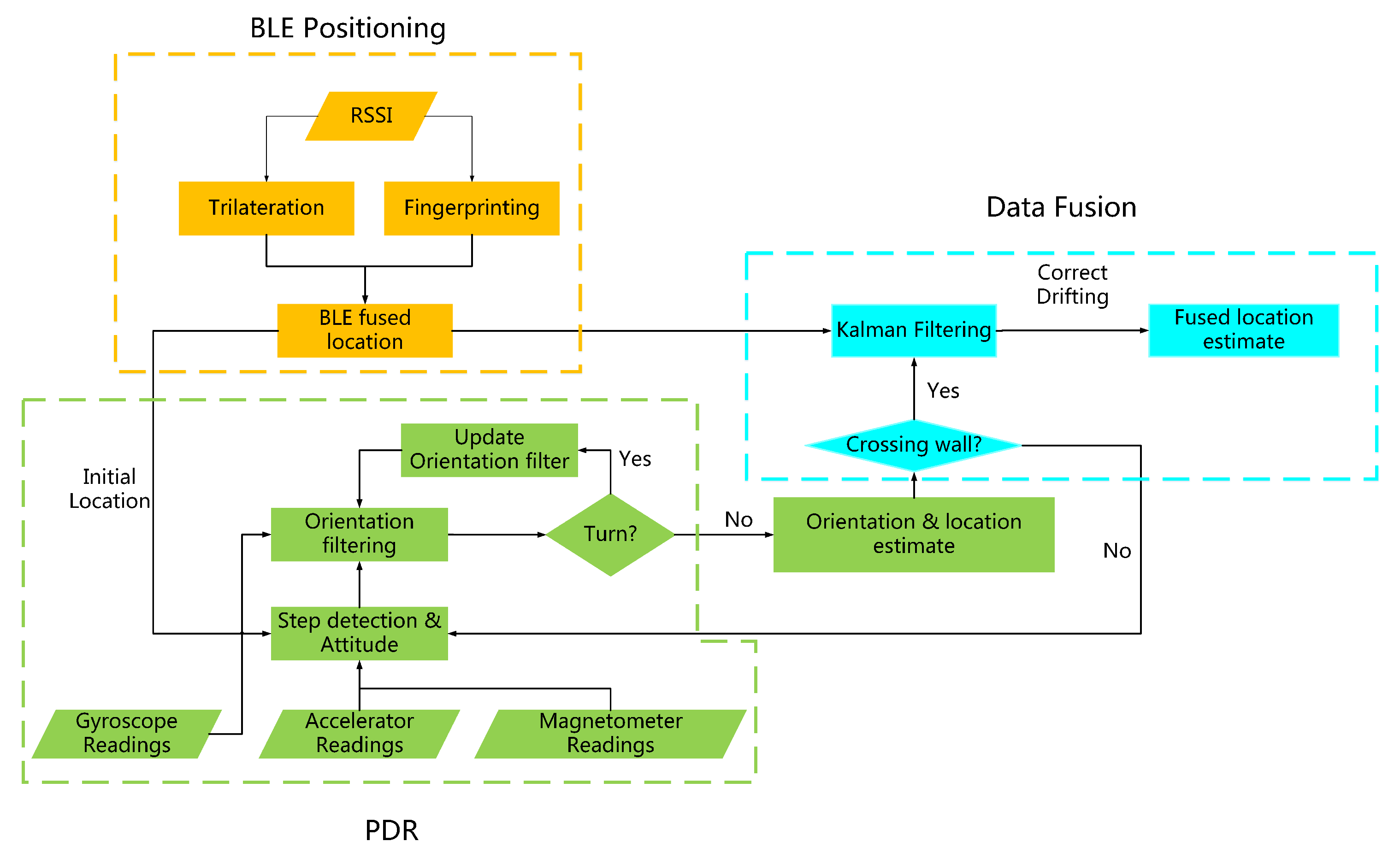
3. Research Method
3.1. Overview
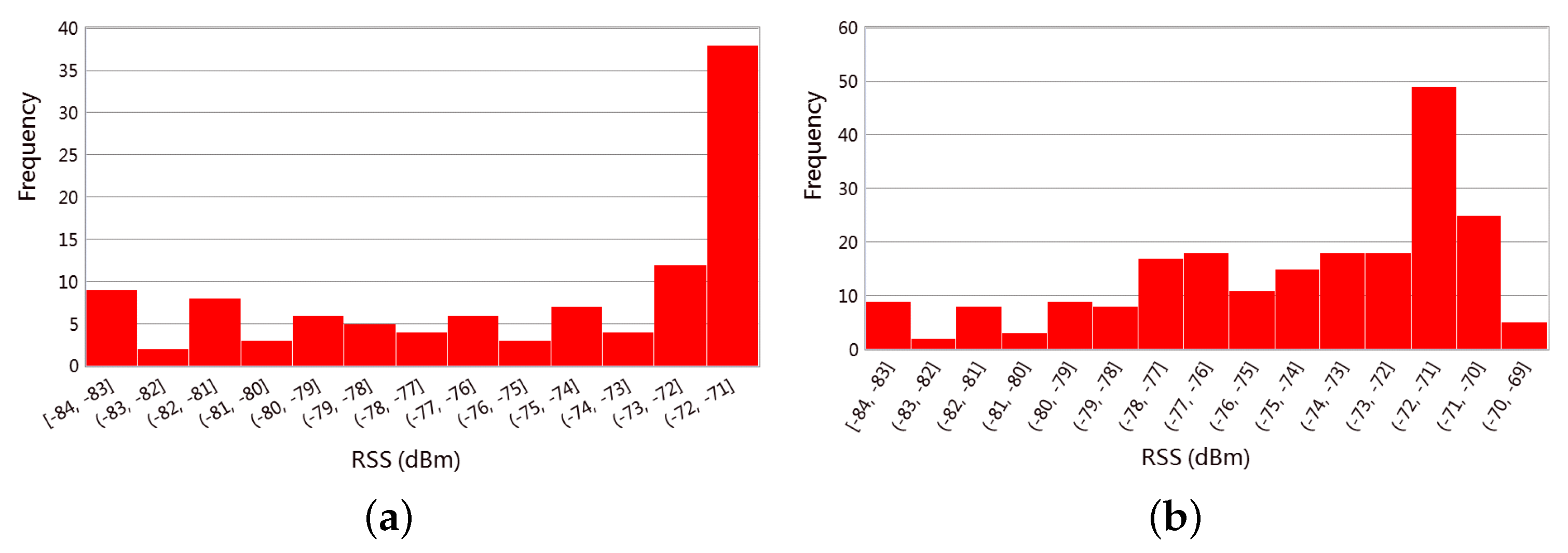
3.2. BLE-Based Method
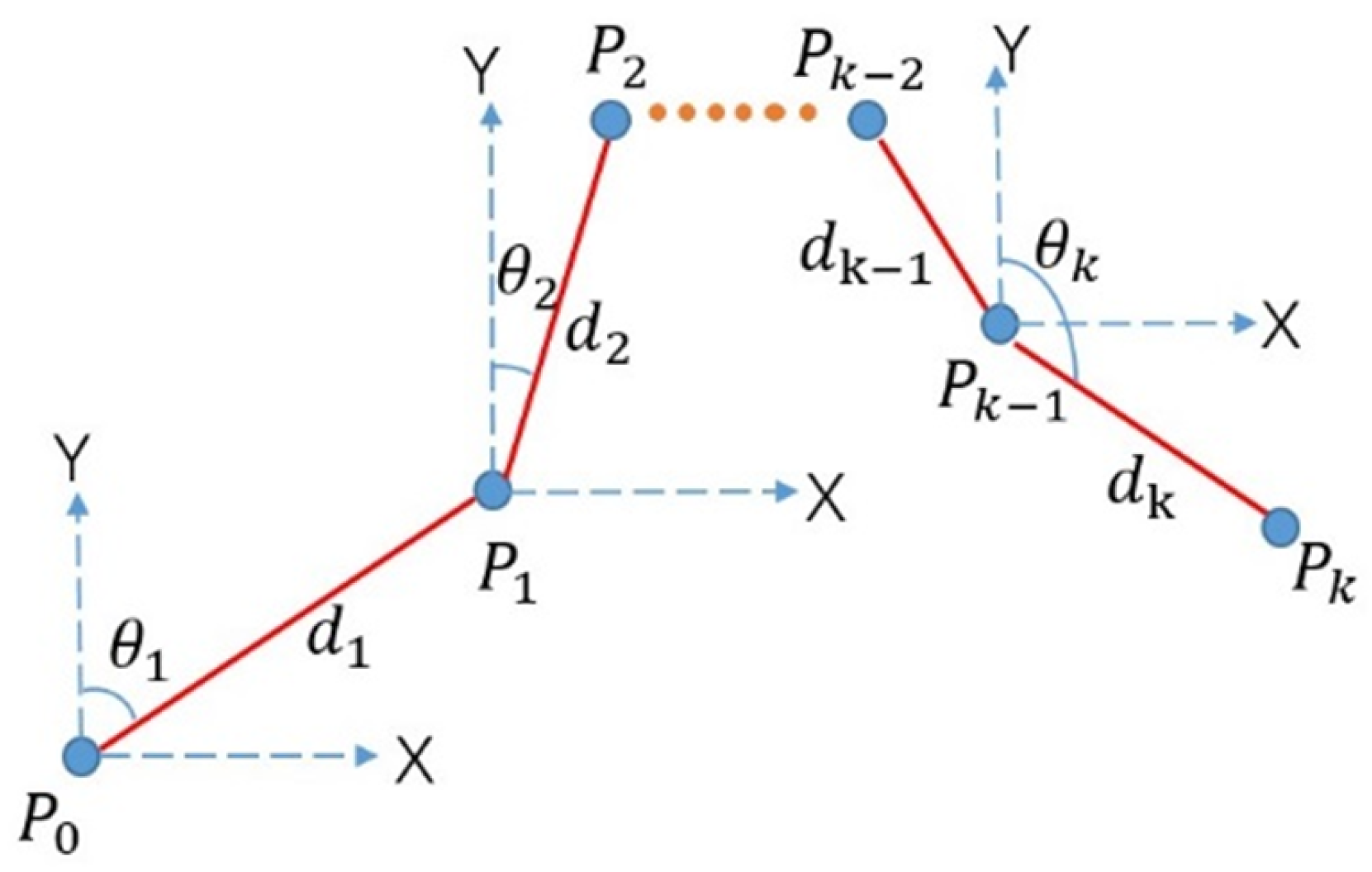
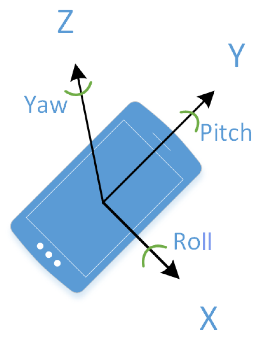
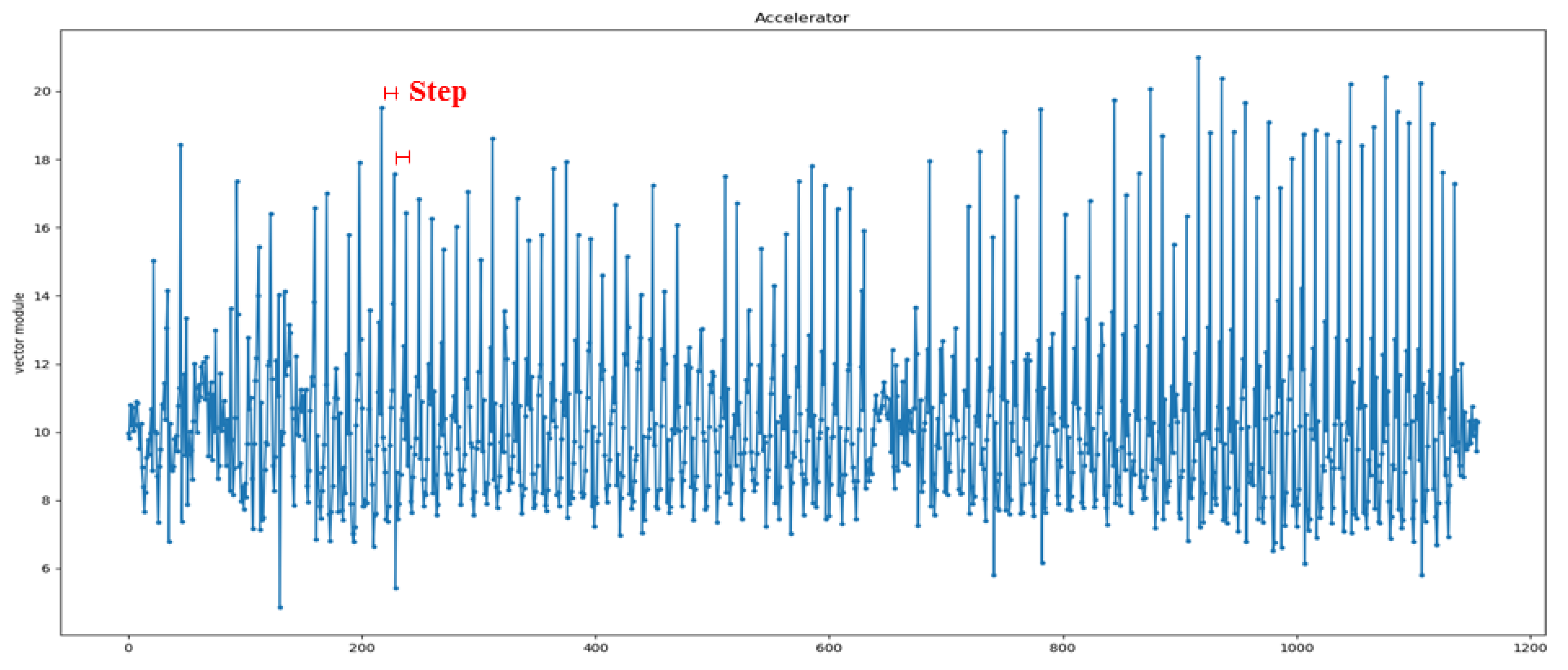
3.3. PDR on Smartphone
3.4. Fusion Method
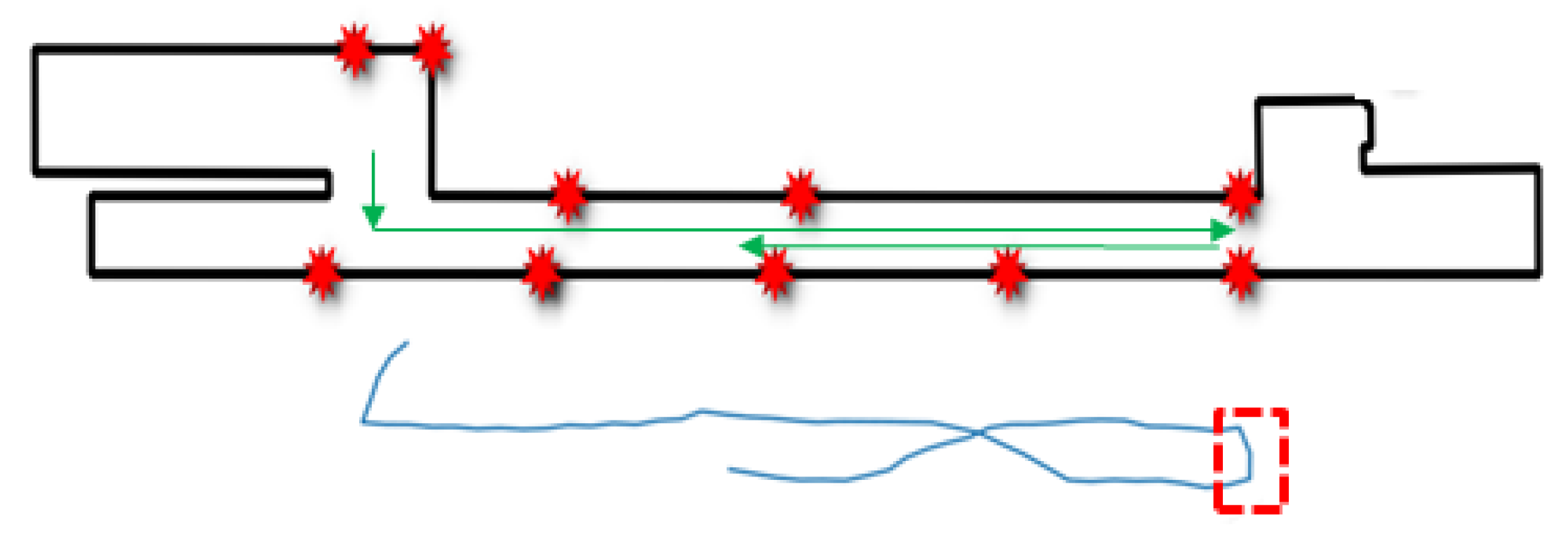
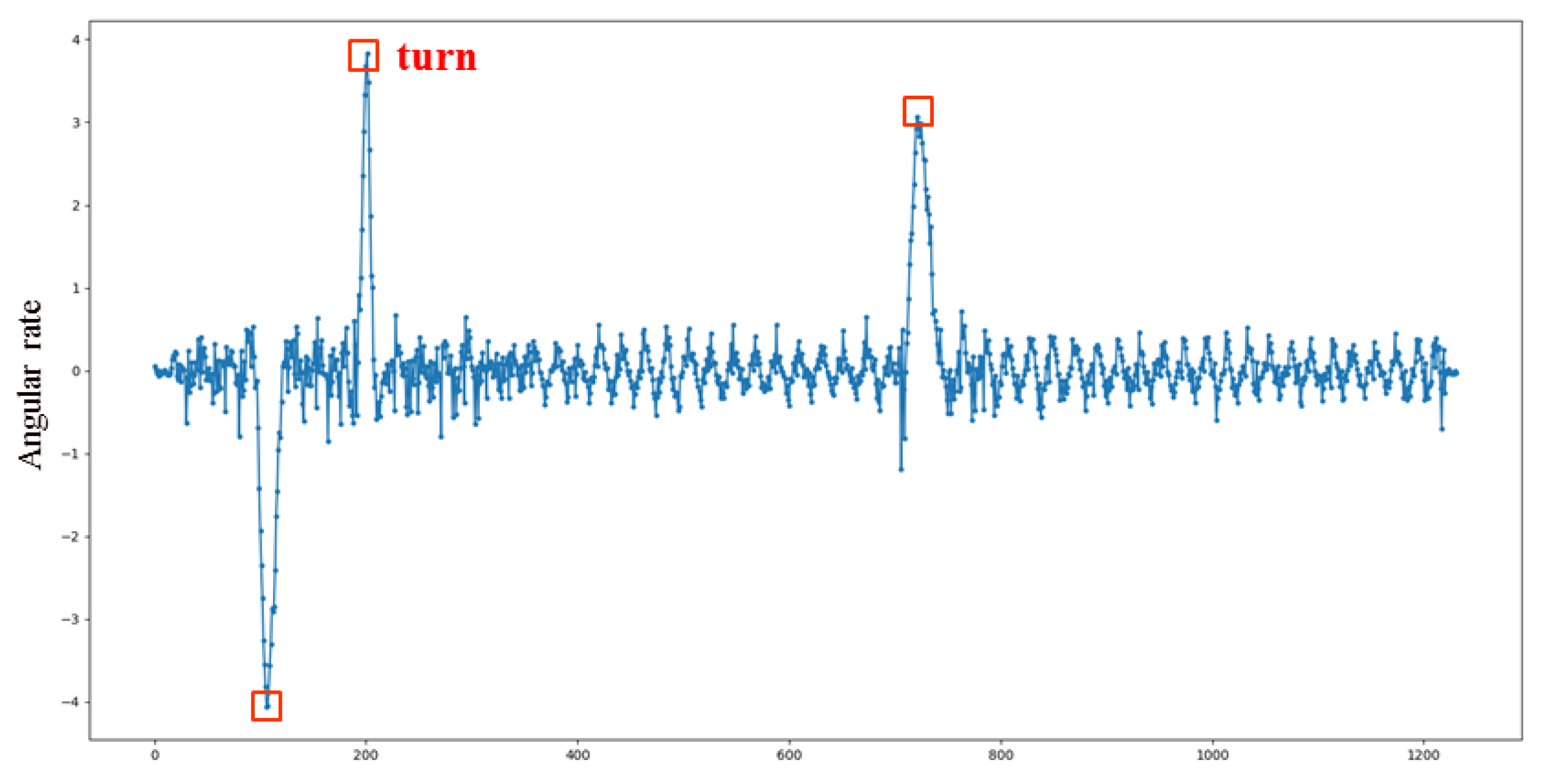
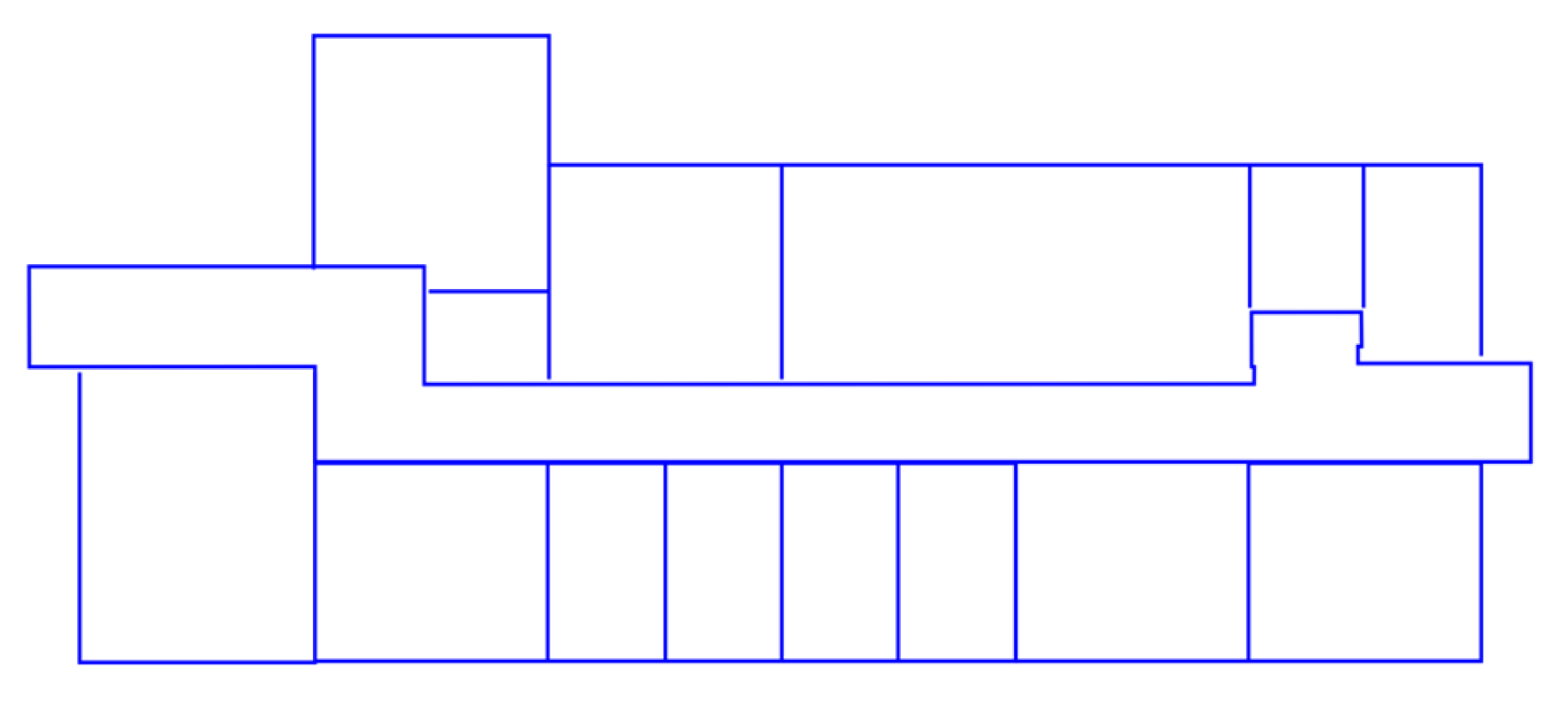
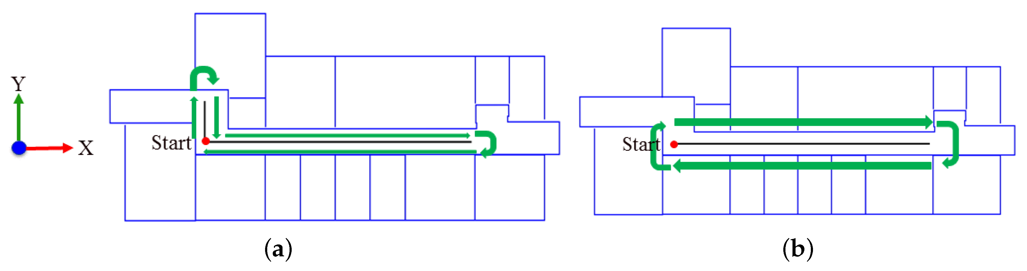
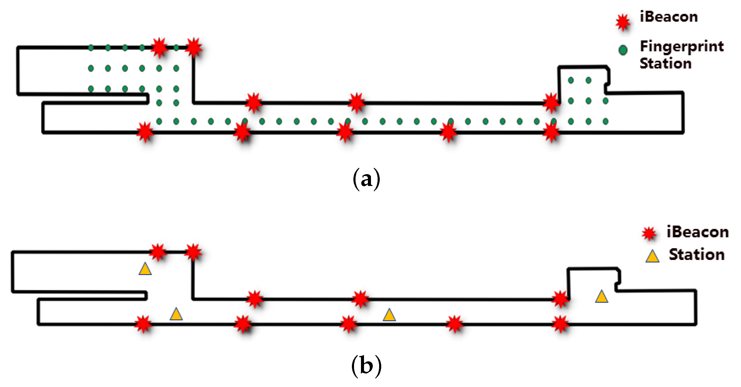
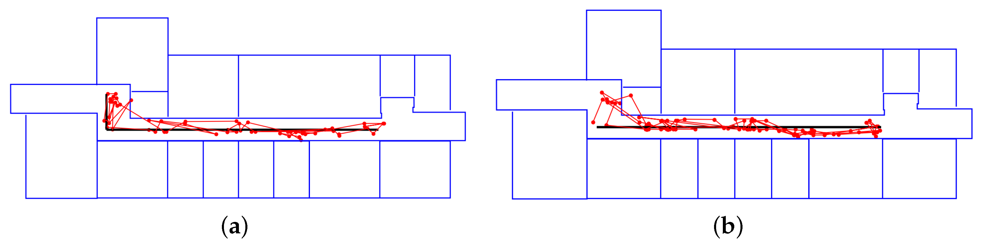
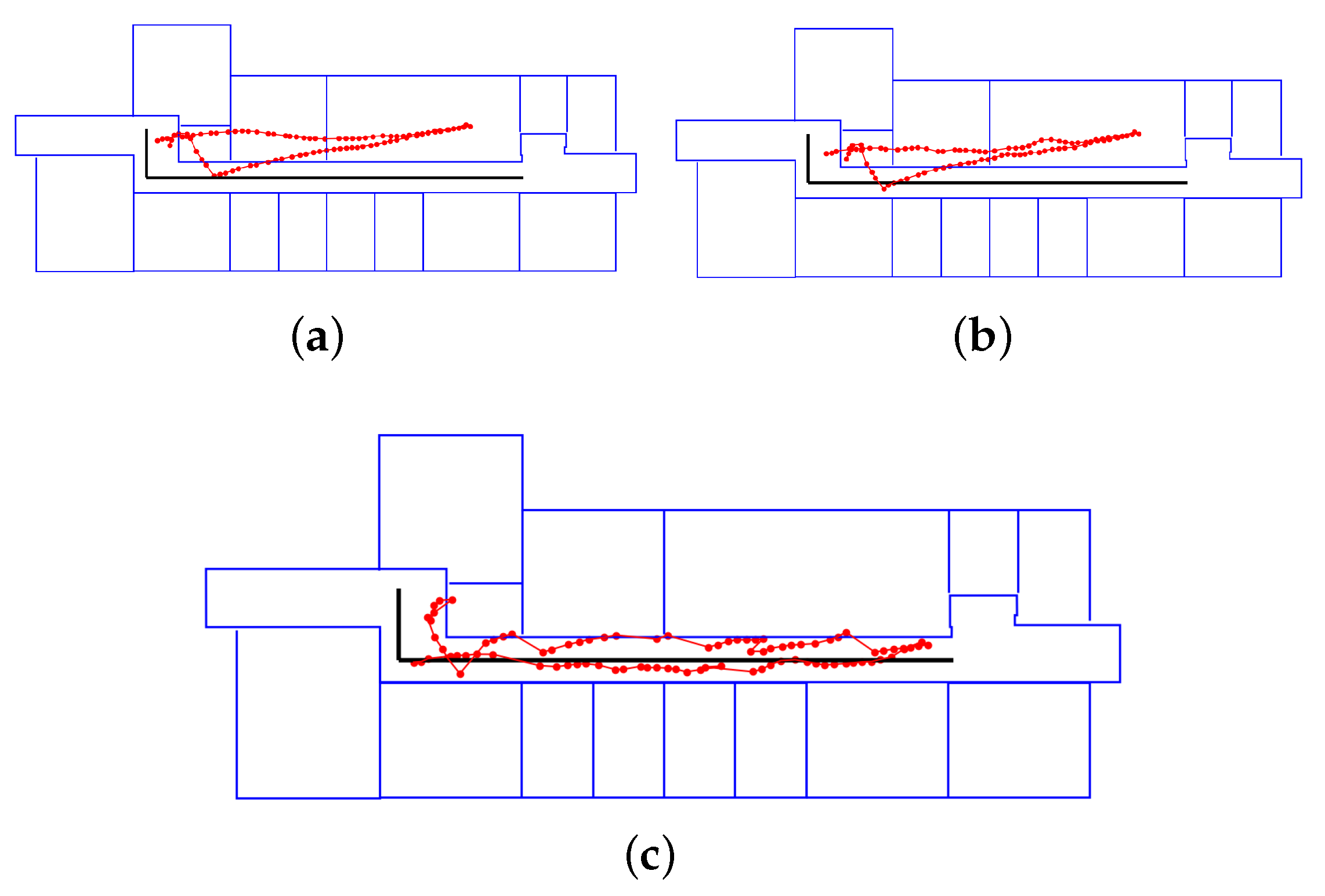
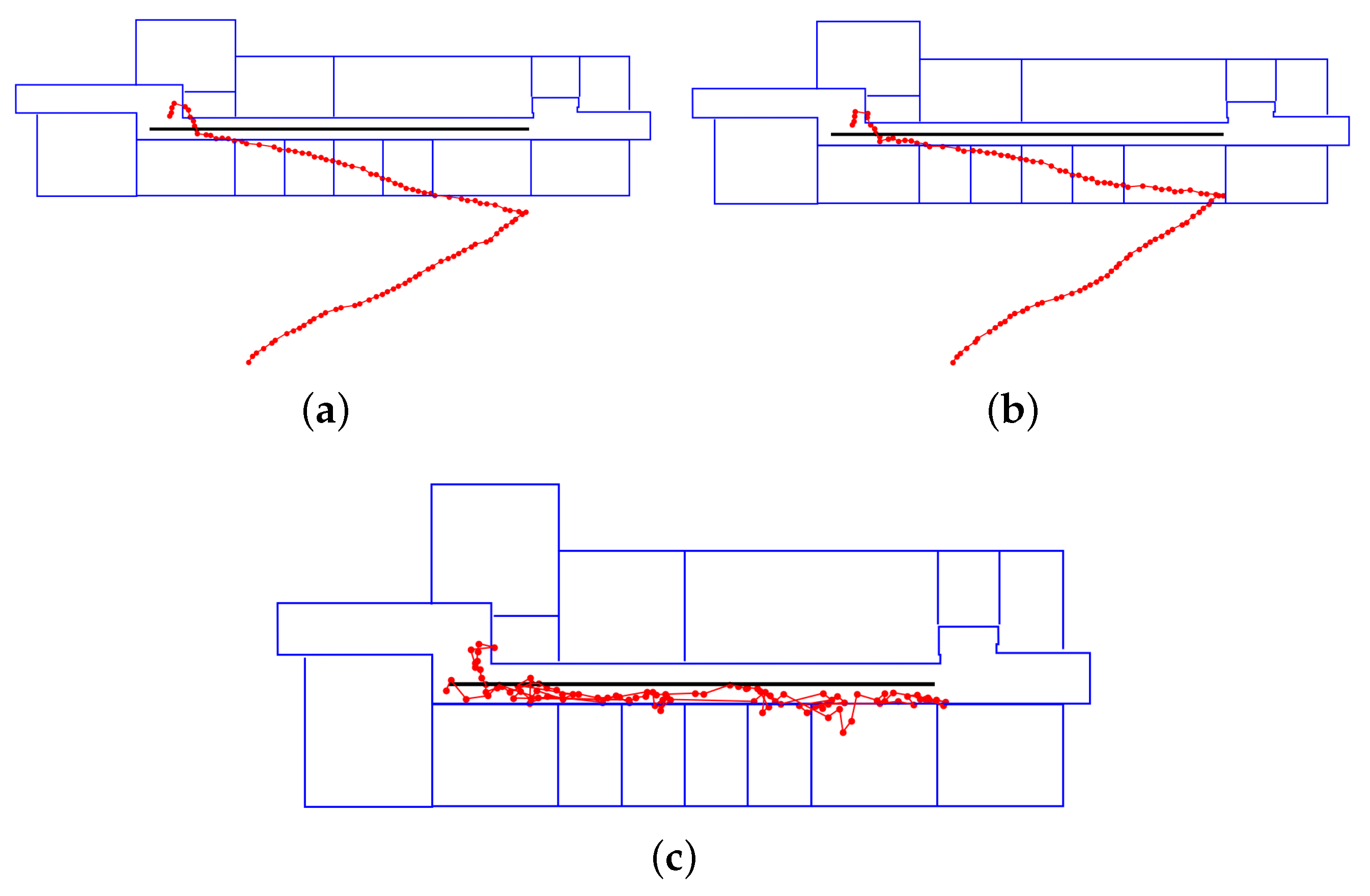
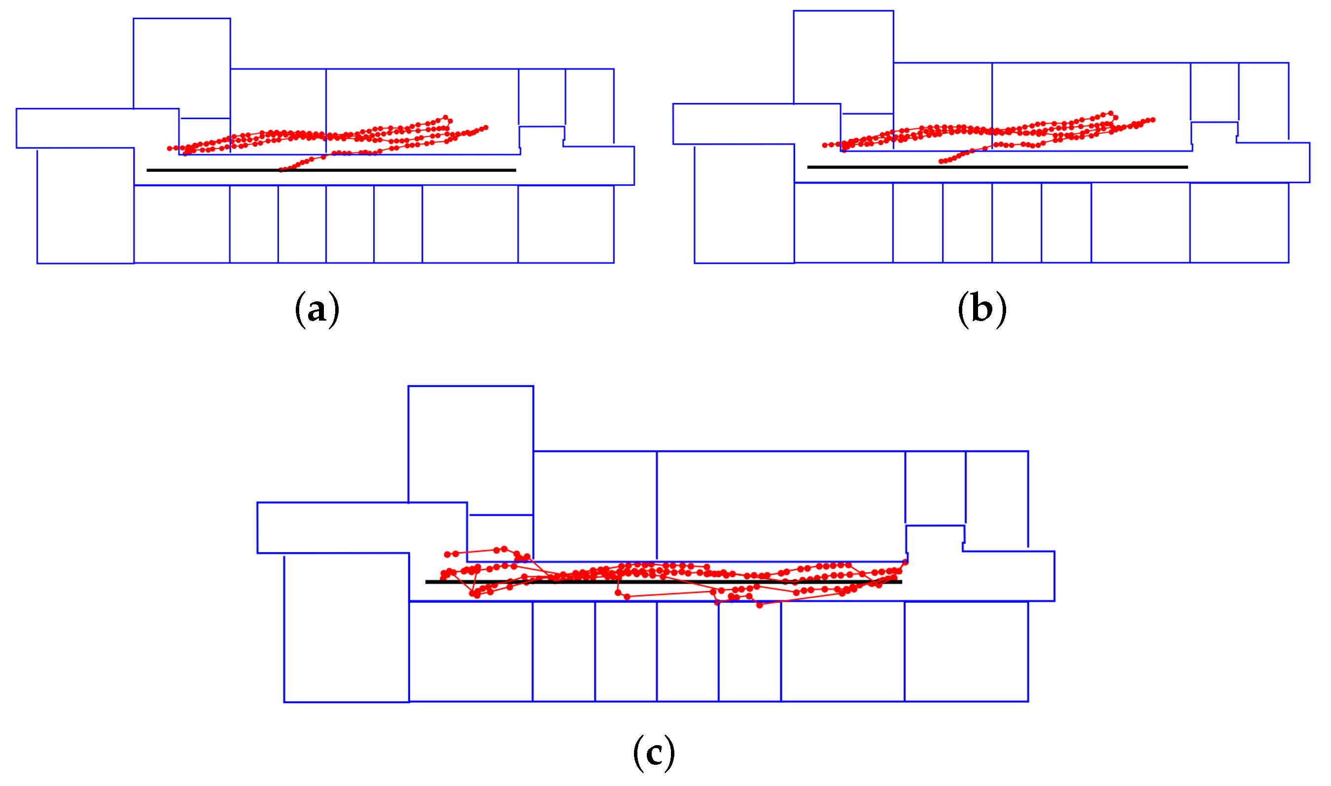
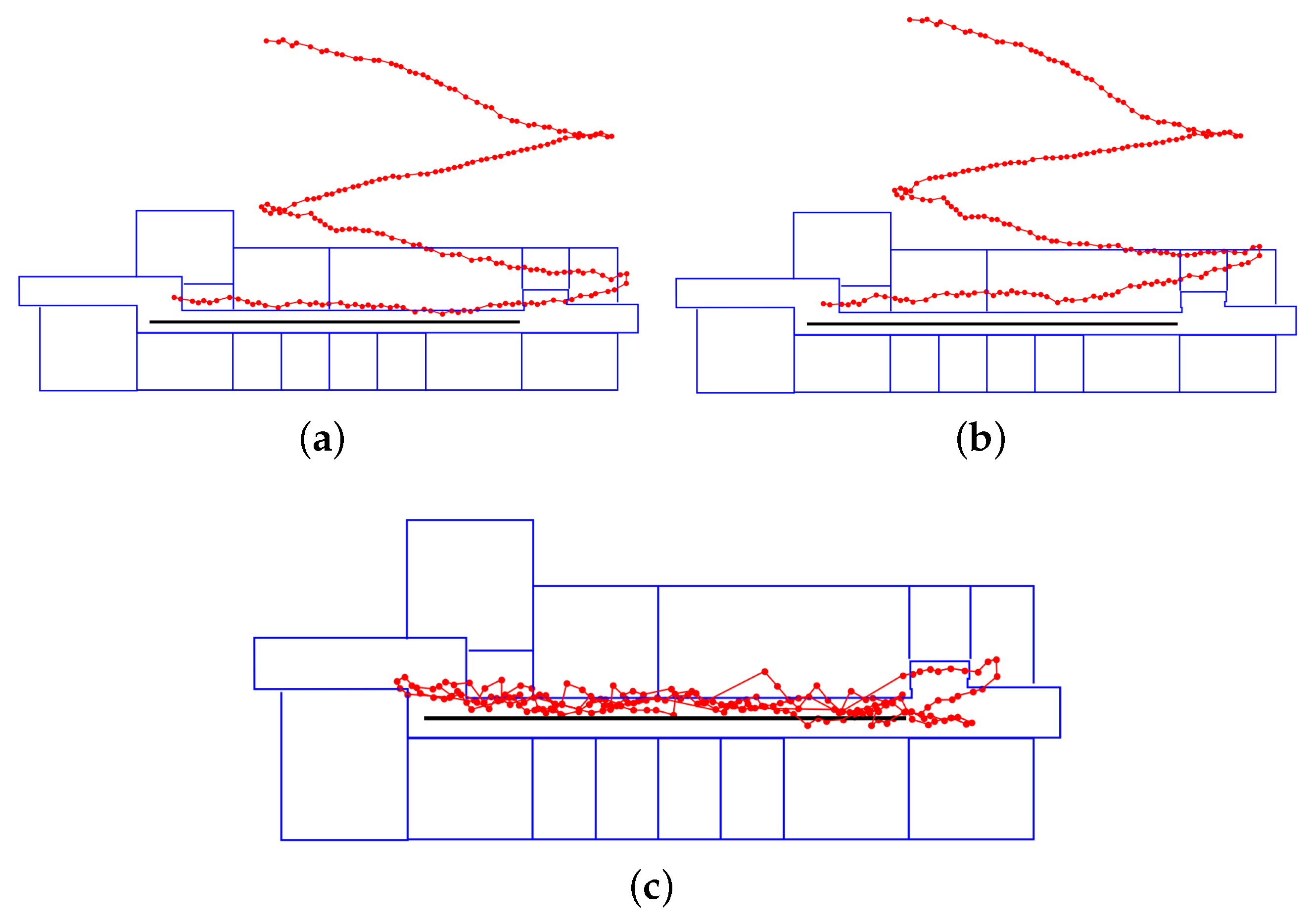
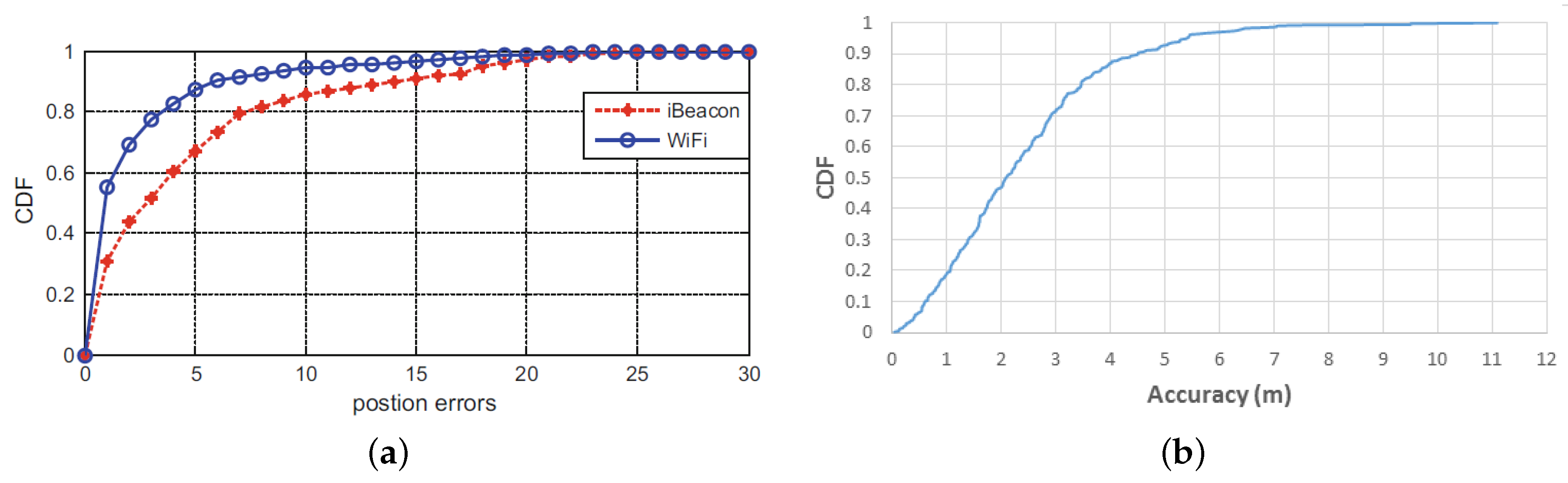
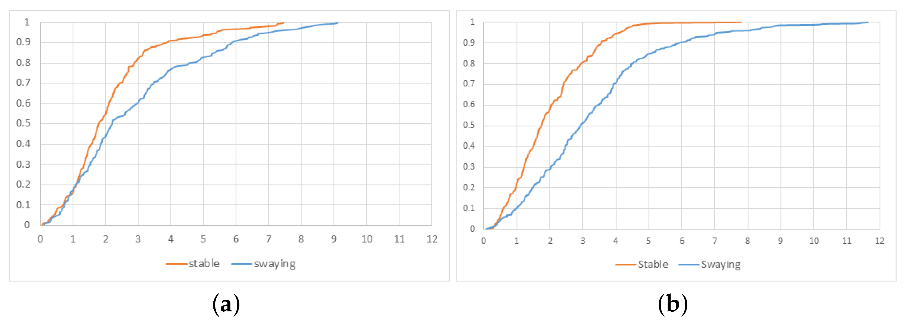
4. Experiment
5. Discussions
6. Conclusions
Author Contributions
Funding
Conflicts of Interest
Abbreviations
| BLE | Bluetooth Low Energy |
| KF | Kalman filter |
| NLOS | non-line-of-sight |
| RSS | received signal strength |
| RSSI | received signal strength indication |
| RMSE | root mean squared error |
| PDR | pedestrian dead reckoning |
| CDF | cumulative distribution function |
References
- Bilke, A.; Sieck, J. Using the Magnetic Field for Indoor Localisation on a Mobile Phone. In Progress in Location-Based Services; Krisp, J.M., Ed.; Springer: Berlin/Heidelberg, Germany, 2013; pp. 195–208. [Google Scholar]
- Chen Ruizhi, C.L. Indoor Positioning with Smartphones:The State-of-the-art and the Challenges. Acta Geod. Cartogr. Sin. 2017, 46, 1316. [Google Scholar] [CrossRef]
- Pivato, P.; Palopoli, L.; Petri, D. Accuracy of RSS-Based Centroid Localization Algorithms in an Indoor Environment. IEEE Trans. Instrum. Meas. 2011, 60, 3451–3460. [Google Scholar] [CrossRef]
- Wan, J.; Yu, N.; Feng, R.; Wu, Y.; Su, C. Localization refinement for wireless sensor networks. Comput. Commun. 2009, 32, 1515–1524. [Google Scholar] [CrossRef]
- Deng, Z.A.; Guofeng, W.; Ying, H.; Di, W. Heading Estimation for Indoor Pedestrian Navigation Using a Smartphone in the Pocket. Sensors 2015, 15, 21518–21536. [Google Scholar] [CrossRef] [PubMed]
- Leppäkoski, H.; Collin, J.; Takala, J. Pedestrian Navigation Based on Inertial Sensors, Indoor Map, and WLAN Signals. J. Signal Process. Syst. 2013, 71, 287–296. [Google Scholar] [CrossRef]
- Li, Y.; Zhuang, Y.; Lan, H.; Zhou, Q.; Niu, X.; El-Sheimy, N. A hybrid WiFi/magnetic matching/PDR approach for indoor navigation with smartphone sensors. IEEE Commun. Lett. 2015, 20, 169–172. [Google Scholar] [CrossRef]
- Li, W.; Wei, D.; Lai, Q.; Li, X.; Yuan, H. Geomagnetism-Aided Indoor WiFi Radio-Map Construction via Smartphone Crowdsourcing. Sensors 2018, 18, 1462. [Google Scholar] [CrossRef]
- Kanaris, L.; Kokkinis, A.; Liotta, A.; Stavrou, S. Fusing bluetooth beacon data with WiFi radiomaps for improved indoor localization. Sensors 2017, 17, 812. [Google Scholar] [CrossRef]
- Fard, H.K.; Chen, Y.; Son, K.K. Indoor positioning of mobile devices with agile iBeacon deployment. In Proceedings of the 2015 IEEE 28th Canadian Conference on Electrical and Computer Engineering (CCECE), Halifax, NS, Canada, 3–6 May 2015; pp. 275–279. [Google Scholar] [CrossRef]
- Faragher, R.; Harle, R. Location Fingerprinting with Bluetooth Low Energy Beacons. IEEE J. Sel. Areas Commun. 2015, 33, 2418–2428. [Google Scholar] [CrossRef]
- Yang, L.; Li, B.; Li, H.; Shen, Y. iBeacon/WiFi Signal Characteristics Analysis for Indoor Positioning Using Mobile Phone. In China Satellite Navigation Conference (CSNC) 2017 Proceedings; Sun, J., Liu, J., Yang, Y., Fan, S., Yu, W., Eds.; Springer: Singapore, 2017; Volume 1, pp. 405–416. [Google Scholar]
- Chen, Z.; Zhu, Q.; Soh, Y.C. Smartphone inertial sensor-based indoor localization and tracking with iBeacon corrections. IEEE Trans. Ind. Inform. 2016, 12, 1540–1549. [Google Scholar] [CrossRef]
- Jenny, R.; Peilin, Z.; Mohamed, A.; Oliver, T. An Improved BLE Indoor Localization with Kalman-Based Fusion: An Experimental Study. Sensors 2017, 17, 951. [Google Scholar]
- Cho, S.Y. Localization of the arbitrary deployed APs for indoor wireless location-based applications. IEEE Trans. Consum. Electron. 2010, 56, 532–539. [Google Scholar] [CrossRef]
- Yang, Z.; Liu, Y. Quality of Trilateration: Confidence-Based Iterative Localization. IEEE Trans. Parallel Distrib. Syst. 2010, 21, 631–640. [Google Scholar] [CrossRef]
- Mirowski, P.; Milioris, D.; Whiting, P.; Ho, T.K. Probabilistic radio-frequency fingerprinting and localization on the run. Bell Labs Tech. J. 2014, 18, 111–133. [Google Scholar] [CrossRef]
- Pelant, J.; Tlamsa, Z.; Benes, V.; Polak, L.; Kaller, O.; Bolecek, L.; Kufa, J.; Sebesta, J.; Kratochvil, T. BLE device indoor localization based on RSS fingerprinting mapped by propagation modes. In Proceedings of the 27th International Conference Radioelektronika (RADIOELEKTRONIKA), Brno, Czech Republic, 19–20 April 2017; pp. 1–5. [Google Scholar] [CrossRef]
- Faragher, R.; Harle, R. An analysis of the accuracy of bluetooth low energy for indoor positioning applications. In Proceedings of the 27th International Technical Meeting of the Satellite Division of the Institute of Navigation, ION GNSS 2014, Tampa, FL, USA, 8–12 September 2014; Volume 1, pp. 201–210. [Google Scholar]
- Chen, J.; Zhang, Y.; Xue, W. Unsupervised Indoor Localization Based on Smartphone Sensors, iBeacon and WiFi. Sensors 2018, 18, 1378. [Google Scholar] [CrossRef]
- Yan, L.; Hoeber, O.; Chen, Y. Enhancing WiFi fingerprinting for indoor positioning using human-centric collaborative feedback. Hum. Centric Comput. Inf. Sci. 2013, 3, 2. [Google Scholar]
- Woo, S.; Jeong, S.; Mok, E.; Xia, L.; Choi, C.; Pyeon, M.; Heo, J. Application of WiFi-based indoor positioning system for labor tracking at construction sites: A case study in Guangzhou MTR. Autom. Constr. 2011, 20, 3–13. [Google Scholar] [CrossRef]
- Hossain, A.M.; Soh, W.S. A survey of calibration-free indoor positioning systems. Comput. Commun. 2015, 66, 1–13. [Google Scholar] [CrossRef]
- Li, F.; Zhao, C.; Ding, G.; Gong, J.; Liu, C.; Zhao, F. A Reliable and Accurate Indoor Localization Method Using Phone Inertial Sensors. In Proceedings of the 2012 ACM Conference on Ubiquitous Computing, UbiComp ’12, New York, NY, USA, 5–8 September 2012; pp. 421–430. [Google Scholar] [CrossRef]
- Qian, J.; Ma, J.; Ying, R.; Liu, P.; Ling, P. An improved indoor localization method using smartphone inertial sensors. In Proceedings of the International Conference on Indoor Positioning and Indoor Navigation, Montbeliard-Belfort, France, 28–31 October 2013; pp. 1–7. [Google Scholar] [CrossRef]
- Zhou, Y.; Zheng, X.; Xiong, H.; Chen, R. Robust Indoor Mobile Localization with a Semantic Augmented Route Network Graph. ISPRS Int. J. Geo-Inf. 2017, 6, 221. [Google Scholar] [CrossRef]
- Park, J.; Chen, J.; Cho, Y.K. Self-corrective knowledge-based hybrid tracking system using BIM and multimodal sensors. Adv. Eng. Inf. 2017, 32, 126–138. [Google Scholar] [CrossRef]
- Sheng, G.; Hanjiang, X.; Xianwei, Z.; Yan, Z. Activity Recognition and Semantic Description for Indoor Mobile Localization. Sensors 2017, 17, 649. [Google Scholar]
- Hafner, P.; Moder, T.; Wieser, M.; Bernoulli, T. Evaluation of smartphone-based indoor positioning using different Bayes filters. In Proceedings of the International Conference on Indoor Positioning and Indoor Navigation, Montbeliard-Belfort, France, 28–31 October 2013; pp. 1–10. [Google Scholar] [CrossRef]
- Akl, R.; Tummala, D.; Li, X. Indoor propagation modeling at 2.4 GHz for IEEE 802.11 networks. In Proceedings of the Sixth IASTED International Multi-Conference on Wireless and Optical Communications: Conference on Wireless Networks and Emerging Technologies, Banff, AB, Canada, 3–5 July 2006. [Google Scholar]


| RMSE XY (m) | RMSE X (m) | RMSE Y (m) | Mean Error X (m) | Mean Error Y (m) | |
|---|---|---|---|---|---|
| Route 1 | 2.71 | 2.57 | 0.85 | 1.90 | 0.60 |
| Route 2 | 2.77 | 2.69 | 0.66 | 2.06 | 0.50 |
| All | 2.75 | 2.65 | 0.74 | 2.00 | 0.53 |
| Trilateration RMSE (m) | Fingerprinting RMSE (m) | |
|---|---|---|
| All | 3.42 | 3.22 |
| Case | RMSE XY (m) | RMSE X (m) | RMSE Y (m) | Mean Error X (m) | Mean Error Y (m) |
|---|---|---|---|---|---|
| Route 1 – inaccurate start | 2.39 | 2.27 | 0.77 | 1.82 | 0.64 |
| Route 1 – disturbed orientation | 3.48 | 3.34 | 0.98 | 2.58 | 0.80 |
| Route 2 – inaccurate start | 2.22 | 2.13 | 0.60 | 1.71 | 0.48 |
| Route 2 – disturbed orientation | 3.66 | 3.54 | 0.92 | 2.74 | 0.70 |
| BLE | Route 1 Inaccurate Start | Route 1 Disturbed Orientation | Route 2 Inaccurate Start | Route 2 Disturbed Orientation | |
|---|---|---|---|---|---|
| CDF 90% (m) | 4.50 | 3.78 | 5.84 | 3.54 | 5.88 |
| 1st Turn Raw Value | 1st Turn Filtered Value | 1st Turn Truth | 2nd Turn Raw Value | 2nd Turn Filtered Value | 2nd Turn Truth | 3rd Turn Raw Value | 3rd Turn Filtered Value | 3rd Turn Truth | |
|---|---|---|---|---|---|---|---|---|---|
| inaccurate start (°) | −208.206 | −199.900 | −180 | 172.384 | 176.029 | 180 | −179.480 | −178.770 | −180 |
| disturbed orientation (°) | −178.126 | −185.673 | −180 | 176.291 | 135.914 | 180 | −152.557 | −149.704 | −180 |
| Our Method | Android | Ground Truth | |
|---|---|---|---|
| Route 1 | 104 | 89 | 102 |
| Route 2 | 179 | 174 | 184 |
© 2020 by the authors. Licensee MDPI, Basel, Switzerland. This article is an open access article distributed under the terms and conditions of the Creative Commons Attribution (CC BY) license (http://creativecommons.org/licenses/by/4.0/).
Share and Cite
Liu, L.; Li, B.; Yang, L.; Liu, T. Real-Time Indoor Positioning Approach Using iBeacons and Smartphone Sensors. Appl. Sci. 2020, 10, 2003. https://doi.org/10.3390/app10062003
Liu L, Li B, Yang L, Liu T. Real-Time Indoor Positioning Approach Using iBeacons and Smartphone Sensors. Applied Sciences. 2020; 10(6):2003. https://doi.org/10.3390/app10062003
Chicago/Turabian StyleLiu, Liu, Bofeng Li, Ling Yang, and Tianxia Liu. 2020. "Real-Time Indoor Positioning Approach Using iBeacons and Smartphone Sensors" Applied Sciences 10, no. 6: 2003. https://doi.org/10.3390/app10062003
APA StyleLiu, L., Li, B., Yang, L., & Liu, T. (2020). Real-Time Indoor Positioning Approach Using iBeacons and Smartphone Sensors. Applied Sciences, 10(6), 2003. https://doi.org/10.3390/app10062003