1. Introduction
Microgrid (MG) systems have been a topic of interest in the electric power industry worldwide. They effectively integrate a mix of solar, wind, and other Renewable Energy Sources (RES). An MG consists of distributed energy generation units, loads and storage systems interconnected through transmission lines and transformers. It can be operated in two modes, either connected to utility grid mode or islanded mode. In the connected mode, the MG gets energy from its own generation units, but in case of power shortage, power will be provided from the main grid. The surplus power can be sold to the main grid as well. In the islanded mode, the MG operates as an independent power system.
MG can be implemented in different areas, ranging from large buildings to isolated rural villages.
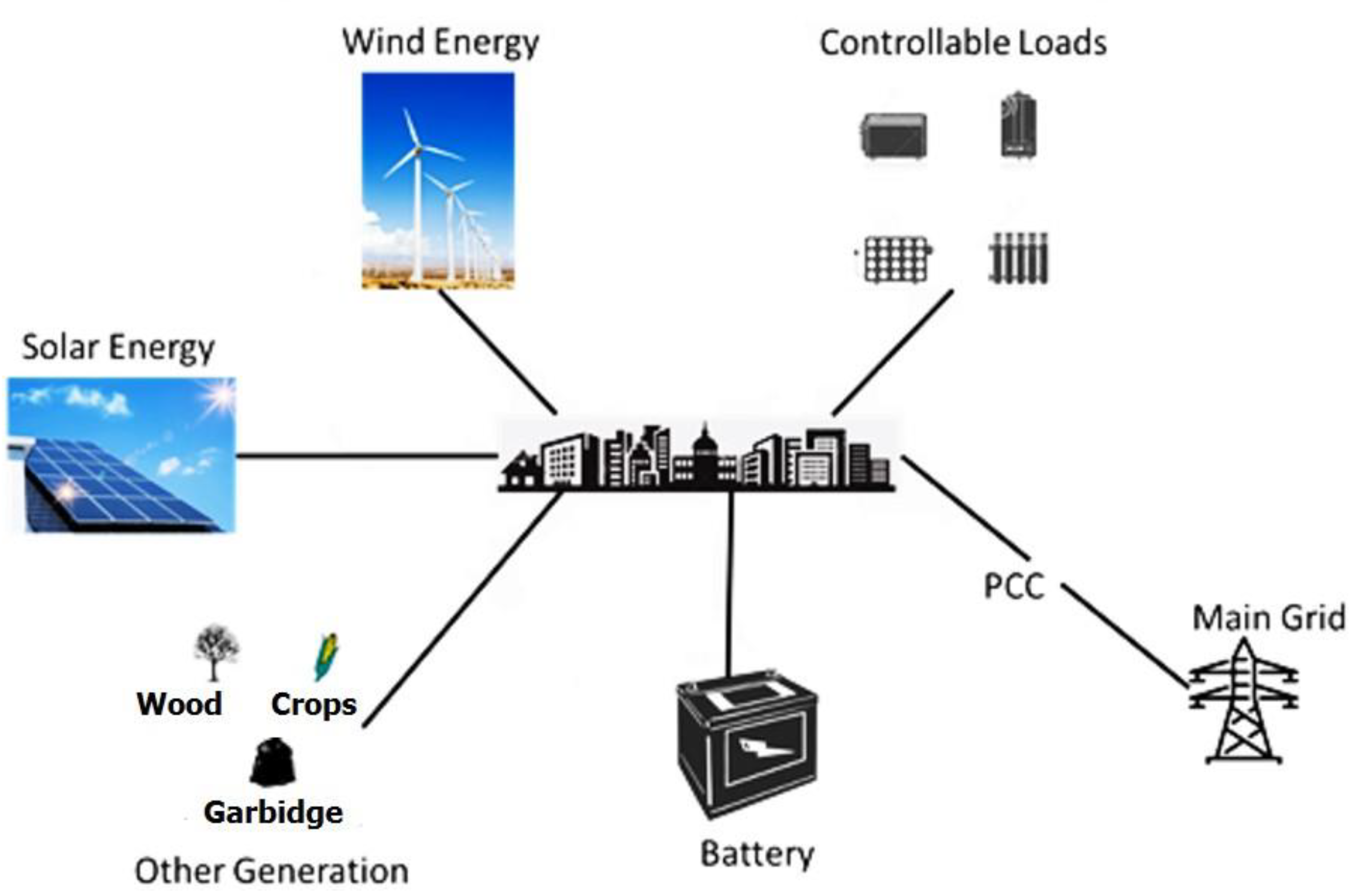
Figure 1 presents a diagram of the MG system. The Point of Common Coupling (PCC) is the main Circuit Breaker (CB) that is used to switch the mode of operation between grid-connected and islanded modes. With several roles and purposes supported by MG, many studies have been made, with emphasis on the MG as a promising field of research [
1,
2,
3]. An overview of the MG system as an essential key in smart energy networks is presented in Reference [
4]. Further, an advanced and functional architecture of MG is proposed by Reference [
5], with details on obstacles that may face MG, especially during the transition between MG operation modes.
A list of existed MG projects over the globe are given in Reference [
6]. For instance, Fort Carson in Colorado Springs is one of several MG projects underway on United States bases under the SPIDERS (Smart Power Infrastructure Demonstration for Energy Reliability and Security) program. The SPIDERS MG is composed of existing assets, a 1 MW PV array and three diesel generators with a total power of 3 MW, and five electric vehicles. The MG project is intended to keep a group of central base facilities operating without grid power as an island, in the event of grid failure. The Sendai MG project was carried out in Japan by New Energy and Industrial Technology Development Organization (NEDO) between 2005 and 2008. The MG showed excellent performance during the 2011 earthquake and tsunami through supplying the teaching hospital of Tohuku Fukushi University with both power and heat for the duration of the two-day blackout. The MG project in Mannheim-Wallstadt, Germany, was implemented by the state utility company in 2006. The main goal of this project was to develop a true MG able to swiftly and smoothly switch from grid-connected mode to island mode. The system is addressed to residential and commercial units and loads.
Power systems resiliency indicates its capability to cope with the faults and any abnormal conditions that could lead to a power blackout. It also allows recovery of the system in order to retrieve its normal operation. The novelty of this paper lies in introducing the level of resilience (LoR) as a measure to compare and evaluate different MG topologies modeled using MATLAB during a fault/attack scenario. The LoR is determined by the sag voltage percentage, the reduction in load served, and the recovery time. Another merit used in determining the LoR is the time needed to reach the power balance state during the absence of the main grid (islanded mode). In such a mode, we studied the effect of the load shedding technique as a strategy to enhance the resilience of MG under attack. It is shown that the placement of MG resources can affect MG resilience, as given by LoR metric. Thus, using this metric, other designs can be investigated to obtain a best-case resilience using the given set of resources.
The rest of the paper is organized as follows:
Section 1.1 presents the latest related work. The topologies and the architecture of the proposed MG are illustrated in
Section 2.
Section 3 presents the resiliency measure formulation.
Section 4 illustrates the resiliency enhancement using Load Shedding technique. Experimental results are shown in
Section 5.
Section 6 summarizes and presents certain future directions.
1.1. Related Work
Various measures of microgrid (MG) system resilience have been explored in the literature. For instance, Reference [
7] presents a method for quantifying the resiliency measure for an MG that is based on networking, Failure rate, and weather factor. In the networking perspective, a connectivity metric is specified by determining the connectivity nature between the installed nodes. Other metrics that have been counted which are the load metric, representing the load that has not been disconnected, due to emergency cases, such as weather problems. Failure rate indicated the robustness degree of the system, and weather factor defined the weather impacts on the system’s resiliency. The blackout duration of the power system is proposed in Reference [
8] as a resiliency measure. This outage may occur due to failure in the distribution system. This paper supposed that the resiliency key of the distributed systems is based on two main factors. These factors are the infrastructure of installed power distributed system, and the restoration priority scheme given by the power company. The proposed measure is tested on a residential electrical power distribution system located in part of the City of Phoenix, Arizona. In Reference [
9], the authors evaluated the resiliency measure of the MG during high-impact low-probability (HILP) windstorms. This resiliency measure is mainly based on performance reduction and other normalized metrics that are utilized for the resiliency comparison process under different operation conditions. A real MG test-bed is utilized to investigate and examine the proposed methods.
A resiliency quantification technique that mainly aimed to provide a non-interrupted power to the critical load is proposed by Reference [
10]. Resiliency estimation is specified as a decision-making problem with multiple measures. It has been quantified through this study by utilizing two approaches, which are: Graph-theoretic approach and Choquet integral. Similar to our work, the simulations of operational contingency scenarios implemented by Reference [
10] validate the fact that resiliency of power system depends on the number of paths connecting source units to loads.
An advanced Code-Based Metric is implemented by Reference [
11] to quantify the resiliency measure of the power distribution system. This resiliency metric is specified via the simulation process that is based on steady-state and dynamic simulation tools. As shown in the results, the utilization of the output data from the proposed technique highly supported the reliability factor of the system by choosing the suitable design of the power distribution system. Like our work, the scheme presented by Reference [
11] can be scalable to different power systems topologies. The concept of Transportable Energy Storage System (TESS) is utilized by Reference [
12] during the investigation of the proposed resiliency metric. The authors of this paper proposed a post-disaster recovery scheme that involved the scheduling process of the TESS, and, in turn, generated resources in MGs to meet cost reduction purpose. The proposed recovery scheme is developed as mixed-integer linear programming. An environment of a modified 33-bus test system with three MGs and four TESSs is utilized to test and analyze the proposed model.
The authors of Reference [
13] studied the resiliency level of different control systems inside an MG network. They also proposed a Cyber-Physical Resilience Metric (CPRM) that is based on utilizing the vulnerability data to specify the system status for monitoring and management purposes. In order to test the proposed metric and study its impact on resiliency, a case study that is relevant to Ukraine cyber-attack is presented.
In our work, we have reviewed some recent strategies on resiliency enhancement for MGs. For instance, optimal scheduling of microgrid system is developed by Reference [
14] to enhance its resiliency. The proposed scheduling procedure is implemented minimizing the load curtailment during the islanded mode operation. It depended on the operations of a centralized control system that is utilized to acquire the needed data and perform the appropriate control commands. It also handled the uncertainty factors of the demand side, generation side, and the transit between operation modes of the MG. The modeling of the normal operation state is achieved via mixed-integer programming. While linear programming is utilized to simulate the resilient operation state. The results of the applied numerical simulation indicated that the proposed model has economic and resiliency merits [
15]. Moreover, these results aimed to reduce the required load shedding by developing a new mathematical model based on the survivability factor. The proposed technique is tested on MG during the stand-alone operation mode. The study is built as an optimization problem framework that is considered as a non-linear and non-convex problem. An interior point optimizer (IPOPT) solver is utilized through this study to solve the proposed problem. Results emphasized on the applicability of the proposed system to improve the resiliency of the MG via performing load shedding processes. Analogous to our scheme [
15], specified the load-shedding algorithm based on the load priority aspect. However, they considered a time-dependent priority through the applied algorithm, while we assumed static load priorities.
The authors of Reference [
16] proposed an MG system as one of the solutions to meet the common concerns of the power systems. It proposed MG solution as part of an organized resiliency plan to reduce the interruption cases of power to critical loads. It also assessed the implementation of MG as a resiliency key, involving its benefits and technical challenges.
A novel distributed noise-resilient secondary control scheme is proposed by Reference [
17]. The proposed control scheme mainly aimed to restore the voltage and frequency parameters. It is implemented on an islanded MG inverter-based with an additive type of noise. Further, the proposed consensus protocols involved both noisy measurements and a non-linear model of the system. MATLAB/SimPowerSystem platform is utilized for simulation purposes to evaluate the performance of the control scheme. Results indicated the effectiveness of the proposed scheme in managing the frequency and voltage parameters and maintaining an accurate proportional real power-sharing.
An algorithm is proposed by Reference [
18] to minimize the electrical losses and operational cost. The algorithm is characterized by its resiliency against the communication delay. It also utilized the adaptive step-size that is based on the maximum rate of the imbalance flow. Following numerical simulation of an IEEE 39-bus system, results indicated that the utilization of the adaptive step-size is more efficient than both diminishing static or constant step sizes. Reference [
19] developed an MG model that mainly focused on the demand response potentials test. The proposed model aimed to increase the financial gain, and provide a resilient model during the islanded operations. A mathematical technique called Benders decomposition is implemented in order to decompose the model into one master problem and two sub-problems. The master problem optimization is relevant to the status of the generation and battery units. The first sub-problem is based on the optimization of the proposed model operation. The second sub-problem is responsible for the resiliency check of the MG in order to verify safe and reliable operation. The results indicated the effectiveness and economic features of the proposed model.
A new control approach for a Direct Current (DC)-MG is proposed by Reference [
20]. An event-triggering communication approach is utilized to provide the data transmission during the inactive status of the Denial of Service (DoS) attack. The stability level of the DC-MG is extracted and derived using both the average dwell-time scheme and the piecewise Lyapunov method.
A resiliency enhancement is covered in Reference [
21] by proposing a dynamic MG system that is mainly utilized to recover the installed critical load after abnormal conditions, such as natural disasters. This process is performed using the installed Renewable Energy Recourses (RESs), storage systems, and the demand response scheme. The paper also specified the needed budgets to restore the normal operation of the distribution system in case of an emergency.
Unlike the aforementioned works, as far as our knowledge, our work introduces a new framework for determining the resiliency of MG systems. This is done by taking into consideration various aspects as opposed to just one aspect (e.g., the recovery time proposed by References [
8,
12], and the fraction of load unaffected by distortion used by Reference [
11]). Our proposed framework is more general as it includes the aspects of voltage sag percentage, load served, recovery time, and time to reach the power balance state. Furthermore, our framework can allow the improvement of MG scheme as it can provide feedback to the design and development process. In addition to that, References [
7,
9,
10,
11] did not consider enabling resiliency as opposed to our work. In our framework, a resiliency enhancement process is achieved by implementing load-shedding algorithm to meet power balance state. Thus, maintaining the service of critical loads.
2. Microgrid Topology
MG has been previously defined as a small controllable power network that is composed of distributed energy resources, load and transmission systems. A basic formulation scheme of an MG is presented in Equations (1)–(3). The sets G, D, and SS, represent generation units, demands, and storage systems, respectively. In G, several generation units can be installed in MG. This includes RES (e.g., Photovoltaic (PV), wind), Diesel Generators (DGs), Main grid source, and other units. A classification of the demand side helps in facilitating the calculation and modeling process.
Each generation system could be classified into several units based on the installation strategy. This classification can be modeled as follow:
The classification of the generation, consumption and the storage stages is considered a useful and valuable step, especially during simulation modeling and calculation processes.
For the sake of illustration, we consider a pair of MGs with identical buses, generation and load units, but with different topologies. These topologies are: Bus topology and Ring topology.
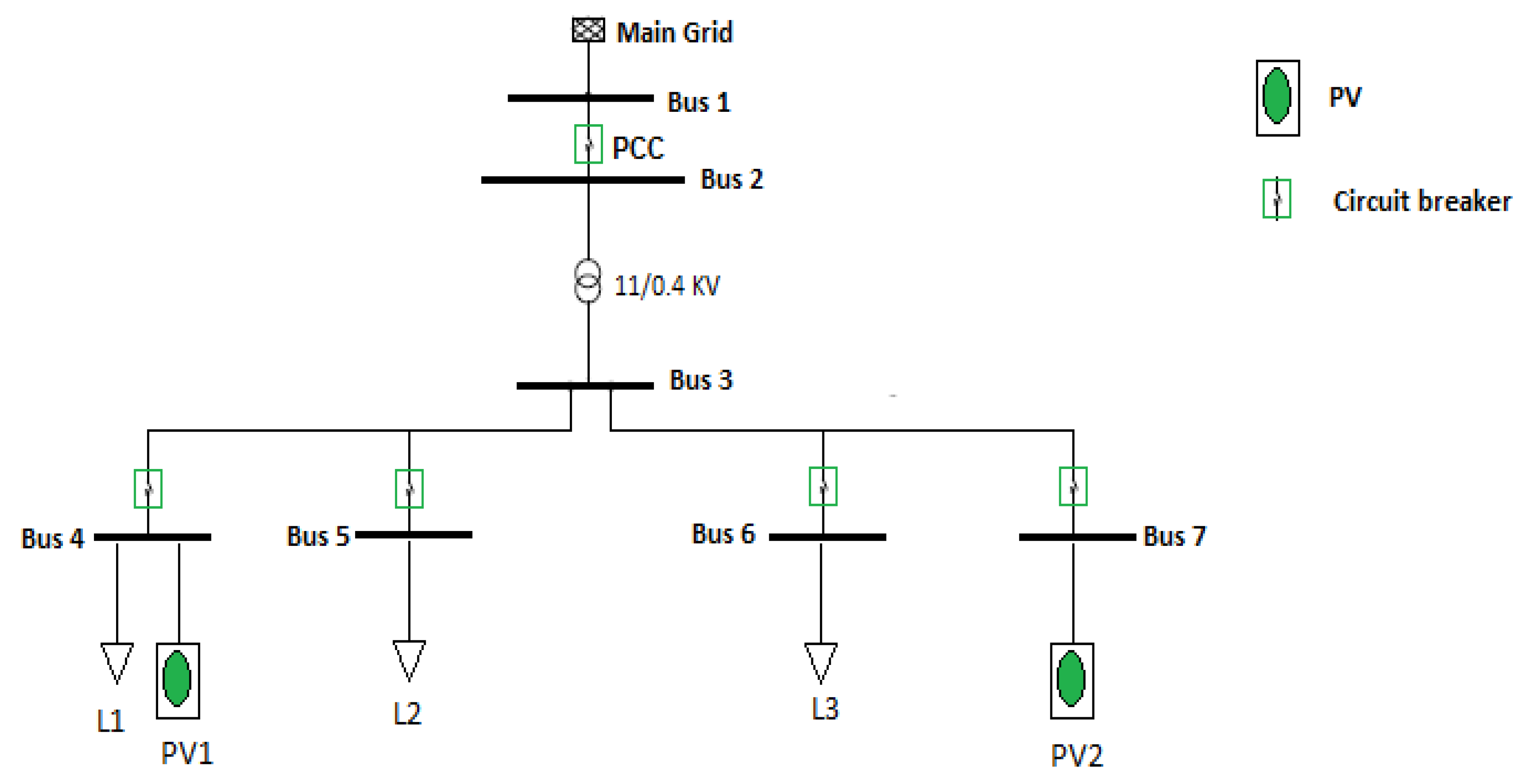
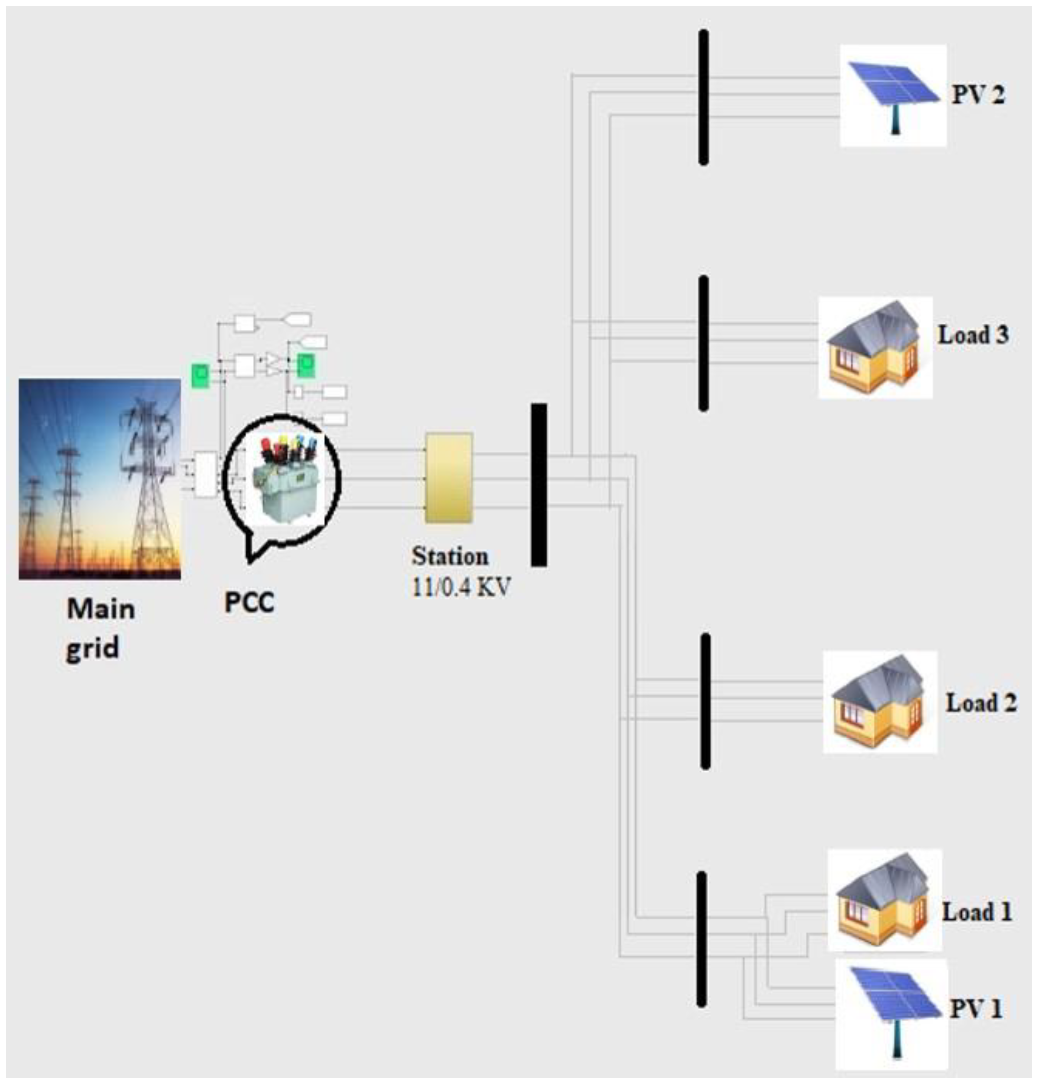
Figure 2 shows the first microgrid, MG
1 with a bus topology, including three loads and two PV systems.
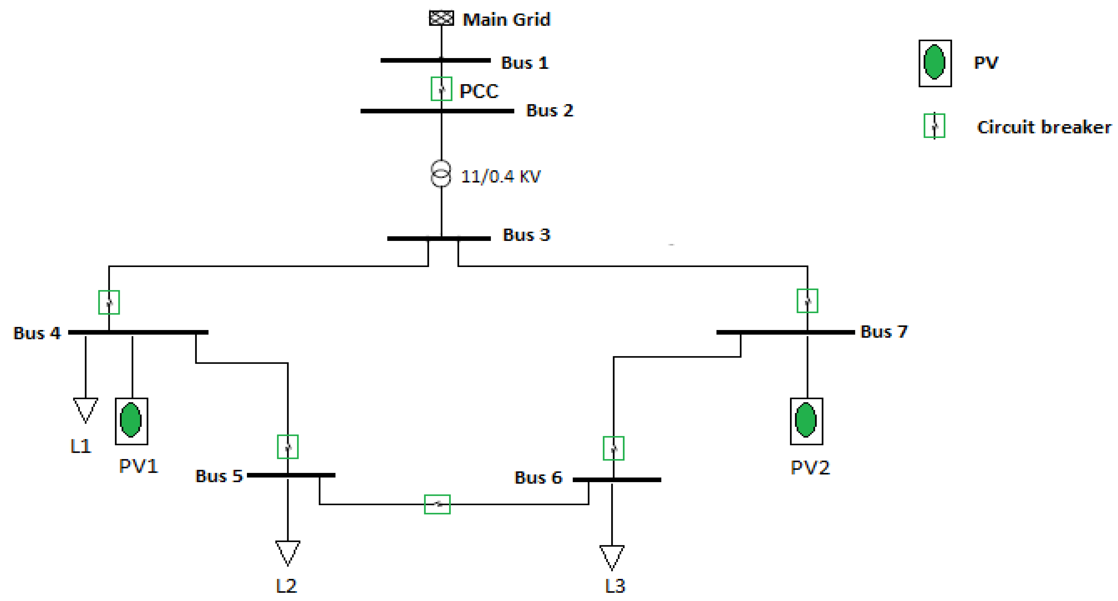
Figure 3 illustrates the ring topology of the second microgrid, MG
2. Both of the topologies have the same parameters of loads, PV, cables and transformers. The rated voltage of the feeder from the main grid is 11 kV. An 11/0.4 kV transformer is installed between the main grid side and low voltage side. Loads L1, L2, and L3 are connected to buses 4, 5, and 6, respectively. PV1 and PV2 have the rated power of 245 kW for each. The Circuits Breakers (CBs) are utilized in order to meet the fault recovery purpose.
3. Resiliency Measure Formulation
The level of resilience (LoR) is the main factor that will be used to capture the evolution of system parameters through the changes of systems modes of operation under a sequence of fault and recovery actions.
For a number of MGs under a sequence of faults/attacks (fault scenario, F), suppose the resulting system modes are denoted by N0 →N1 →… → Nj, where N0 is the initial mode, while Ni is the mode after the ith fault and reconfiguration (i = 1, …, j).
This work investigates a number of factors as a way to compare the resiliency of MGs. These factors are the voltage sag percentage, load served, recovery time, and time to reach power balance state.
Definition 1. Given the sequence of mode switches: N0→ N1 →…→Nm, (under a fault scenario F), the voltage sag [22] can be defined as follow: One of the other vital resilience factors is level of performance reduction (). is investigated through this study as the load percentage that is served during faults and recovery actions.
Definition 2. Given the sequence of modes: N0→ N1 → … → Nm, (under a fault scenario F), thereduction is given by:
Furthermore, Recovery Time (RT) is considered one of the vital resiliency factors in LoR formulation.
The aforementioned factors have been investigated during the connected mode operation. Regarding the islanded mode, the time to power balance () factor has been tested. This factor indicates the time needed to meet the power balance state.
Definition 3. Given the sequence of modes: N0→N1→…→Nm, Tb can be formulated as:
where,
Pg is the generated power,
Pc is the consumed power,
is the time where the generated power is equal or greater than the consumed power.
is the time where the MG is operated in the islanded mode.
A system is more resilient if it incurs a smaller sag percentage, or otherwise, a smaller loss of performance, or otherwise a smaller level of recovery-time, or otherwise, a smaller level of time to meet power balance state.
Definition 4. Given a set of microgrids, MG ≡MGk; k{1, …, y}, where y is the number of the microgrids, and an attack/fault scenario F, we say that LoR((MGi, F) > LoR((MG-MGi, F) if: 4. Resiliency Enhancement Using Load Shedding
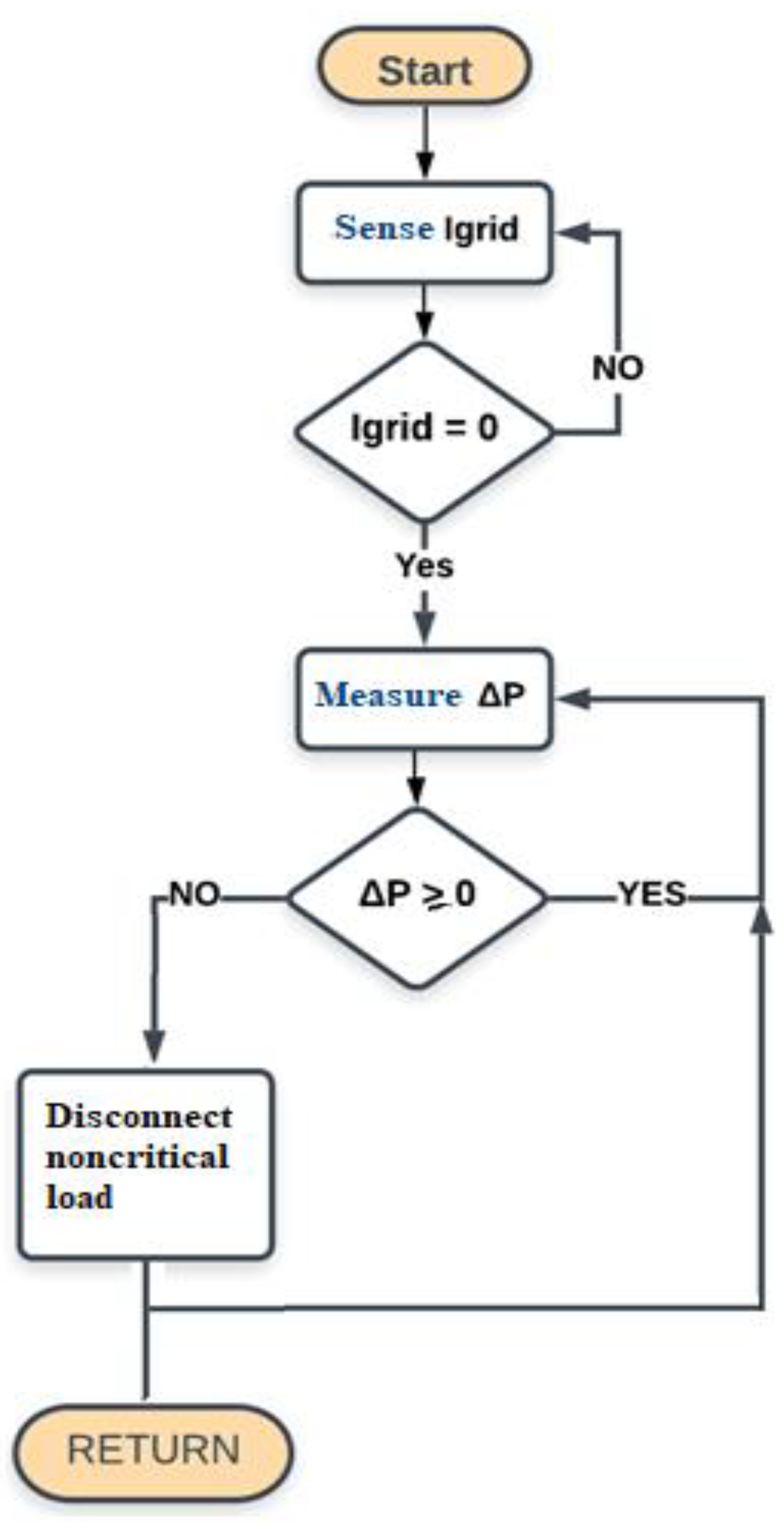
In the islanded mode, we studied the resiliency enhancement using load shedding technique. This technique is mainly based on covering the critical demand in case of the absence of the main grid. Algorithm 1 illustrates the applied scheme. This algorithm starts by continuously sensing the current flowing from the main grid towards the MG. Next, the difference between the generated power and the consumption power,
is computed as given in Equation (10). In general, the power balance state is achieved when the generated power equals the consumed power, as shown in Equations (11) and (12) [
23].
| Algorithm 1: Load shedding |
| 1 Input: Igrid, , |
| 2 Output: perform load shedding |
| 3 Start program |
| 4 Sense the Igrid at PCC |
| 5 If (Igrid = 0) |
| 6 calculate |
| 7 endif |
| 8 If ∆P = 0 |
| 9 Disconnect noncritical load |
| 10 endif |
| 11 While Igrid = 0 and ∆P < 0 |
| 12 perform load shedding |
| 13 End while |
| 14 Stop |
where
and
can be given as:
where is the power from the main grid,
is the
PV output power,
is the diesel generator power,
is the storage systems power during the discharging,
is the demand power,
the storage systems power during the charging operation.
has positive, or negative, or zero values. The positive value of the parameter means that the generated power is more than the demand. In this case, and since there is no storage system in the built-model, other mechanisms can be applied to benefit from this case economically and environmentally. For instance, surplus power can be sold to other organizations, MGs, institutions, etc. On the other hand, if the sign of the parameter is negative. This means that the demand side is more than the generated power. Other strategies have to be implemented to maintain a stable and reliable operation of the system.
Through this paper, a load shedding algorithm has been implemented to decrease the demand side utill the power balance state is achieved. The load shedding algorithm is defined as the process of gradual load disconnection in terms of their serving priorities. In addition to that, the zero value of
indicates the balance state between the generation and the consumption sides.
Figure 4 represents the load shedding flowchart. The load shedding is conducted by disconnecting the non-critical loads in ascending order.
5. Experimental Results
The two MGs models are constructed in the MATLAB/Simulink platform version 2018b.
Figure 5 shows the MG
1 model, involving the aforementioned MG components. The left side shows the main grid as well as the PCC breaker that connects MG
1 with the utility grid. An 11/0.4 kV transformer is installed between the main grid and the main station. The right side shows the connections between three loads and two PV systems.
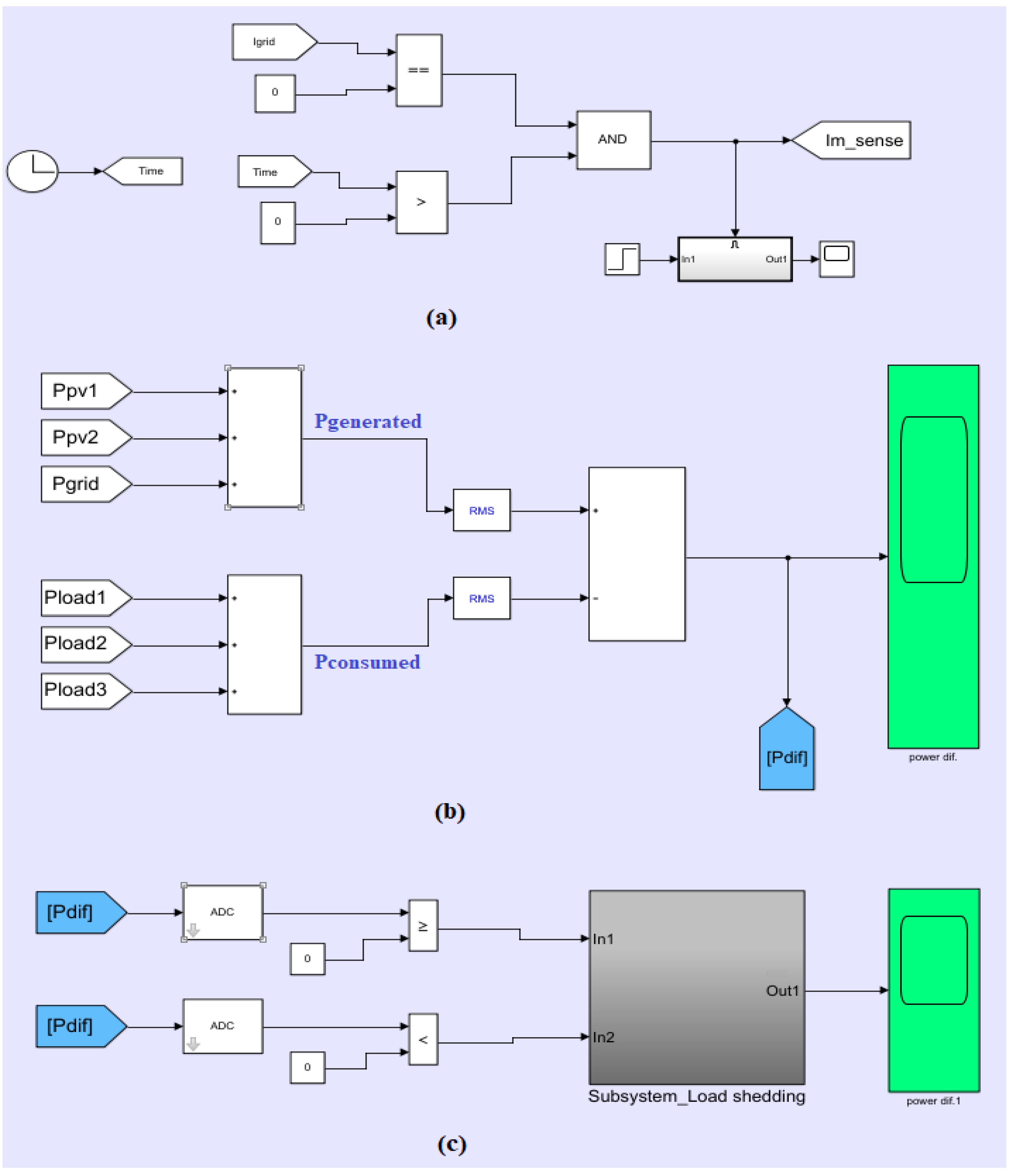
Following Algorithm 1,
Figure 6a shows the current sensing model of the main grid. In this model, the current signal is monitored continuously and fed into a comparator. If the measured current reaches 0 A, the comparator will trigger the power difference (
computation phase.
Figure 6b shows the computation of
between the generated and the consumed power values. The generated power is the summation of acquired power signals of PV1, PV2, and the main grid, respectively. While the consumed power is the summation of the power signals of L1, L2, and L3, respectively. Both power generated and consumed signals are fed to RMS conversion block in order to calculate the
signal.
Figure 6c illustrates the load shedding process in order to meet the power balance state. The process starts by utilizing the
continuously and forwarding it to an Analog to Digital Converter (ADC). Then, if
value is negative, the non-critical load is disconnected using an ON/OFF signal. For the computation of voltage sag percentage parameter, a voltage signal at the main station is continuously measured and fed to an RMS converter block to extract the RMS values.
To evaluate the two MGs factors to different fault types, two faults have been inserted in sequence on different times and at different locations. Fault 1 occurred at bus 5, while fault 2 occurred at bus 1. Generally, electrical faults can be classified into two types, which are: Symmetric faults and Asymmetric faults [
24]. Symmetric fault indicates the three-phase fault, which means that all phases are affected by the fault occurrence. The asymmetric fault is called unbalanced fault, which means that not all the phases are affected by the fault. Typically, asymmetric faults are classified into three types, which are: Line-to-Line (L-L) fault, Line-to-Ground (L-G) fault and Line-to-Line-to-Ground (L-L-G) fault.
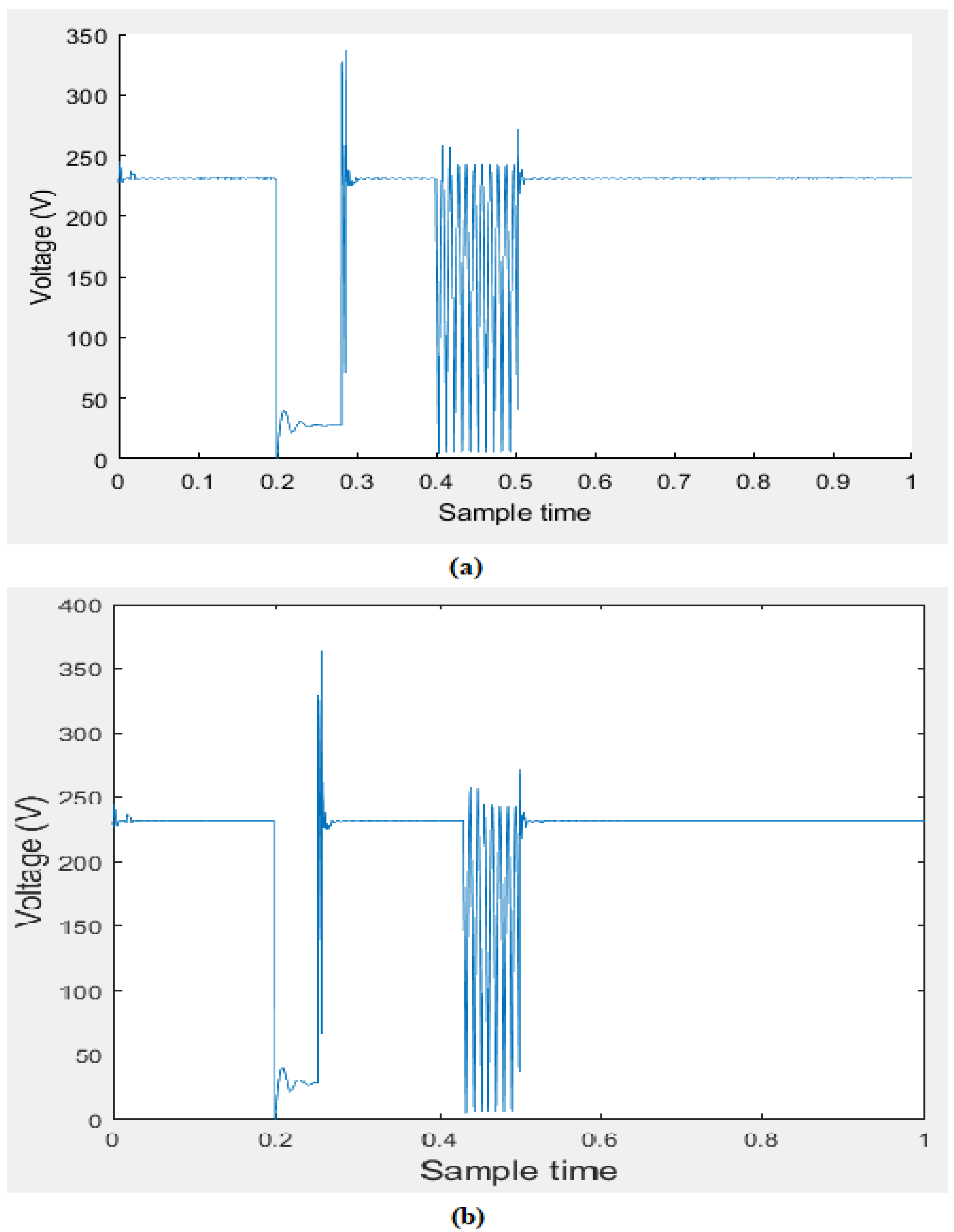
The two inserted faults to our models are symmetric fault (fault 1) and asymmetric fault; L-L type (fault 2). As fault 1 is applied at t = 0.2 sec at bus 5 and cleared by the simultaneous opening of Circuit Breaker (CB). For MG
1, this fault has caused a decrease in the voltage parameter from 230 V to 39.7 V at bus 3, as shown in
Figure 7a, resulting in a voltage sag of 82.7%. L2 will be disconnected as a result of the fault recovery process. Therefore, and based on Equation (8), the
is about 31%.
A second fault is applied at t = 0.42 sec at bus 1. This fault has a critical feature which is the location. To maintain the stable operation of MG
1, the PCC will be opened. Therefore, MG
1 will be transmitted from the connected mode to islanded mode at t = 0.5 sec. MG
1 will operate as an independent power source in the islanded mode, as shown in
Figure 8.
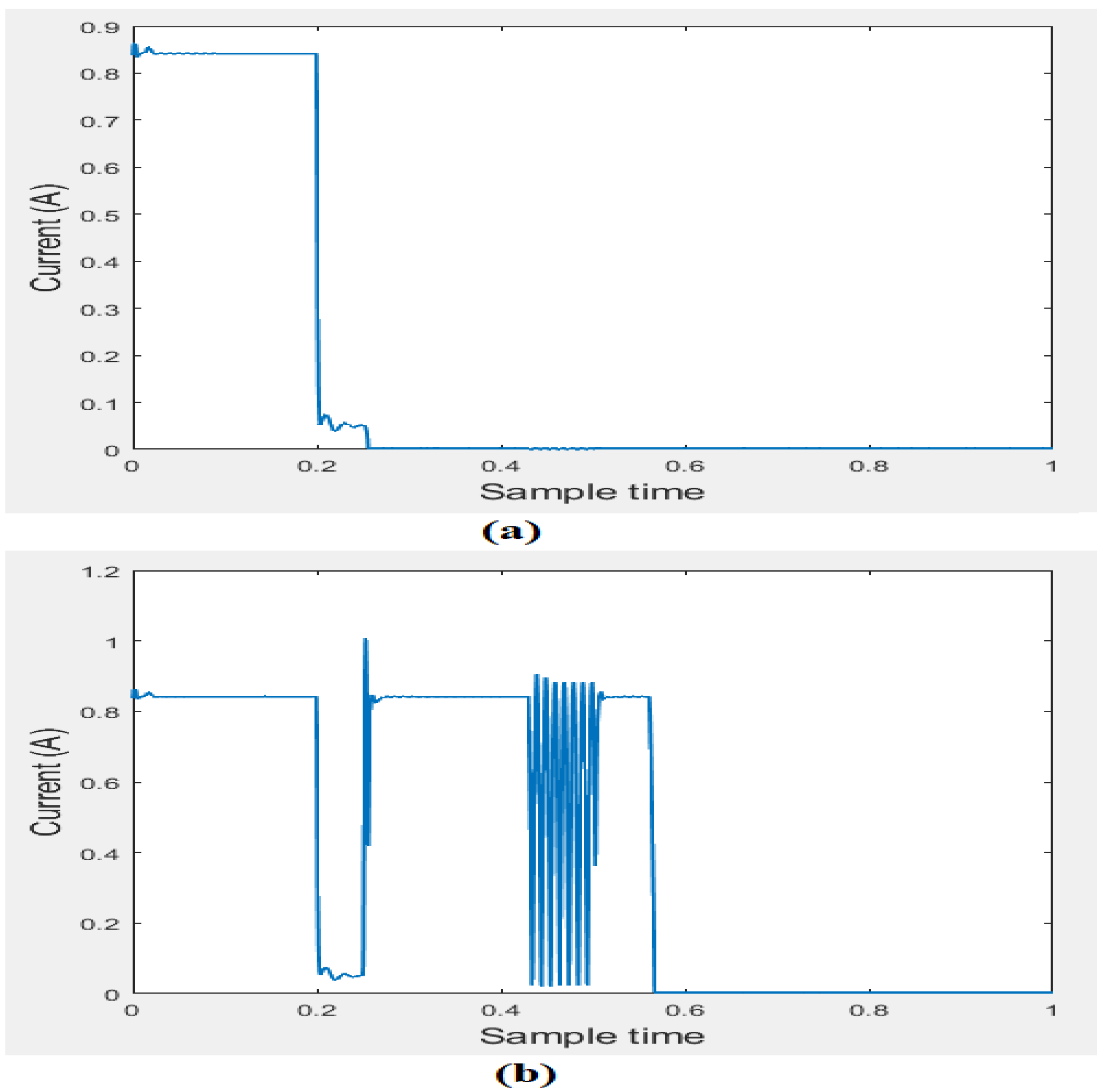
Figure 9a shows the current signal of L2, where the load has been disconnected at about t = 0.28 sec as bus 5 is disconnected. The voltage sag parameter has a value of 96%.
On the contrary, when applying the same sequence of faults for MG
2, L2 is still connected after fault1 via feeding it with another redundant path through bus 6. Hence, the
is going to be zero, since there is no load disconnection. The voltage sag values of the MG
2 has approximately the same values of 83% and 96.1% during fault 1 and 2, respectively, as shown in
Figure 7b. Under the second fault, fault2, similar to MG
1, MG
2 will be transmitted to islanded mode at t = 0.5 sec.
Figure 9b shows the current signal of L2 during the ring topology.
During the islanded mode, maintaining a reliable operation is one of the vital priorities that have to be covered. Therefore, in order to sense the accurate time of the MG transition to islanded mode, a current sensing system is built to sense the current signal of the main grid source. As shown previously in
Figure 8, it can be noticed that
= 0.5 sec for both MG
1, and MG
2.
For both MGs, as the main grid current (I
grid) goes to 0 A at t = 0.5 sec, the power difference,
is calculated. In this example, L3 is assumed to be the most critical load, while L2 has lower priority than L1
where
is the priority of L2 and
is the priority of L1. In MG
1, the gradual load shedding process starts its operation by disconnecting L1, since L2 has been already disconnected during the connected mode. By the load disconnection,
goes to a positive value, and hence, meets the power balance state, as shown in
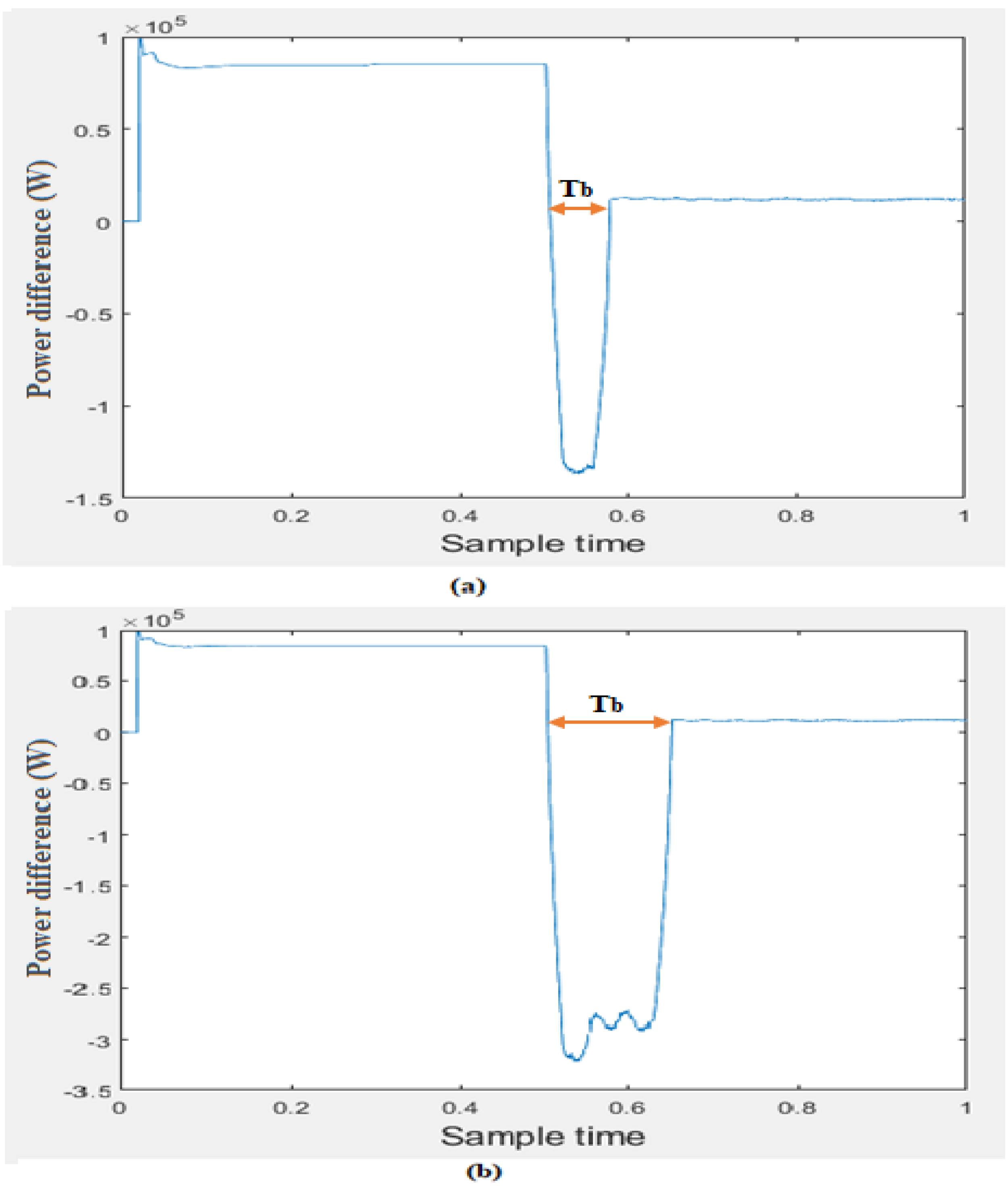
Figure 10a. Following Equation (9), the
parameter has the value of 0.06 s. While in MG
2, the load shedding starts by disconnecting L2. The
value is decreased, as shown in
Figure 10b; however, it is still negative. Therefore, and based on the proposed algorithm, another disconnection operation of L1 is needed to meet the power balance state. Hence, the
parameter has the value of 0.12 s.
Frequency is like the pulse of the power system, and its status indicates the imbalance between generation and real power demand.
Figure 11 illustrates the frequency signals for MG
1 and MG
2, respectively. It can be seen that when the power balance state is reached, the frequency is maintained at its nominal value (50 Hz).
For comparing LoR of MG1 and MG2, under a fault scenario F. MG1 has higher LoPR (31%) as opposed to MG1 (0%) during the connected mode. Whereas, both MG1 and MG2 have almost the same voltage sag percentage (96%). Then following definition 4, LoR (MG2, F) > LoR (MG1, F). Thus, MG2 is more resilient to fault scenario F as compared to MG1.
