Article

Identification Method of Geometric Deviations for Multi-Tasking Machine Tools Considering the Squareness of Translational Axes

1
Department of Mechanical Systems Engineering, Tokyo University of Agriculture and Technology, Tokyo 184-8588, Japan
2
Technical Staff, Monodzukuri Center, Osaka Institute of Technology, Osaka 535-8585, Japan
3
Tokyo University of Agriculture and Technology, 2-24-16 Nakacho Koganei, Tokyo 184-8588, Japan
*
Author to whom correspondence should be addressed.
Appl. Sci. 2020, 10(5), 1811; https://doi.org/10.3390/app10051811
Submission received: 18 February 2020 / Revised: 2 March 2020 / Accepted: 3 March 2020 / Published: 6 March 2020
(This article belongs to the Special Issue Manufacturing Metrology)

Abstract

:
Some methods to identify geometric deviations of five-axis machining centers have been proposed until now. However, they are not suitable for multi-tasking machine tools because of the different configuration and the mutual motion of the axes. Therefore, in this paper, an identification method for multi-tasking machine tools with a swivel tool spindle head in a horizontal position is described. Firstly, geometric deviations are illustrated and the mathematical model considering the squareness of translational axes is established according to the simultaneous three-axis control movements. The influences of mounting errors of the measuring instrument on circular trajectories are investigated and the measurements for the B axis in the Cartesian coordinate system and the measurements for the C axis in a cylindrical coordinate system are proposed. Then, based on the simulation results, formulae are derived from the eccentricities of the circular trajectories. It is found that six measurements are required to identify geometric deviations, which should be performed separately in the B axis X-direction, in B axis Y-direction, in C axis axial direction, and three times in C axis radial direction. Finally, a numerical experiment is conducted and identified results successfully match the geometric deviations. Therefore, the proposed method is proved to identify geometric deviations effectively for multi-tasking machine tools.

1. Introduction

In recent years, multi-tasking machine tools have become widely popular in industry because of their growing capabilities in performing complex motions and in reducing machining time and cost. Therefore, many researchers research their machining capabilities and processing technology [1,2,3]. Based on the basic configuration of a lathe or turning machine, multi-tasking machine tools are developed by equipping with a swivel tool spindle head, which can perform not only a turning operation but also a drilling or milling operation [4]. With the increase of the functionality and the number of simultaneously controlled axes, multi-tasking machine tools are difficult to achieve high machining accuracy and efficiency. Therefore, it is essential to investigate the factors affecting the accuracy of finished products which are machined by multi-tasking machine tools. There are two kinds of factors which could affect the machining accuracy, which are geometric errors of machines operating under no-load or quasi-static conditions and kinematic errors during processing. The geometric errors of machines include the geometric errors of the components and the accuracy of assembly of machine tool executive units. The kinematic errors during processing may be caused by thermal distortion [5], chatter vibrations [6], cutting force or component stiffness [7]. The research in this paper is to establish an effective measurement method for identifying geometric errors of multi-tasking machine tools to improve the motion accuracy under a no-load condition.
Up to now, identification methods of the geometric deviations for five-axis machining centers by using the ball bar, the R-test, a touch-trigger probe or other measuring instruments have been proposed by many researchers. For example, J.R.R. Mayer et al. proposed five tests by the ball bar with a single setup to assess the axis motion errors of a trunnion-type A-axis [8]. W.T. Lei et al. used the ball bar to inspect motion errors of the rotary axes on five-axis machining centers. As a result, the servo mismatch of the rotary axes was successfully detected and the gain mismatch errors could be eliminated by tuning the velocity gains of the position control loops of all servo-controlled linear and rotary axes [9,10]. Tsutsumi et al. proposed an algorithm for identifying particular deviations relating to rotary axes in five-axis machining centers [11]. Tsutsumi et al. applied the ball bar to diagnose the motion accuracy of simultaneous four-axis control movements for identifying the eight deviations inherent to five-axis machining centers [12]. Tsutsumi et al. also investigated the kinematic accuracy of five-axis machining centers with a tilting rotary table by two different settings of the ball bar in simultaneous three axis motion [13]. They corrected the squareness deviations of three translational axes for identifying the geometric deviations inherent to five-axis machining centers with an inclined A-axis [14]. S.H. Yang et al. measured and verified the position-independent geometric errors of a five-axis machining center using the ball bar [15]. In addition, other researchers also used the ball bar to explore the measurement and identification methods for geometric errors of five-axis machining centers with a tilting rotary table [16,17,18] or in universal spindle head type five-axis machining centers [19]. On the other hand, R-test has been applied recently to investigate the geometric deviations identification method for the five-axis machining centers with a swiveling head [20,21]. Ibaraki et al. identified the kinematic errors of five-axis machining centers by developing a simulator and a set of machining tests [22,23]. The simulator graphically presented the influence of rotary axis geometric errors on the geometry of a finished workpiece measured by R-test [24,25,26,27,28]. Furthermore, other measuring instruments and methods are also developed to investigate the geometric deviations for five-axis machining centers. Ibaraki et al. applied a touch-trigger probe to calibrate the error map of the rotary axes for five-axis machining centers by means of on-the-machine measuring of test pieces [29]. J.R.R. Mayer et al. estimated all axis to axis location errors and some axis component errors of a five-axis horizontal machining center by probing a scale enriched reconfigurable uncalibrated master balls artefact [30]. Beñat Iñigo et al. proposed a new strategy to simulate the calibration and compensation of volumetric error in milling machines of medium and large size and laser trackers are used to optimize volumetric error calibration processes [31]. E.Diaz-Tena et al. studied a radical new ‘multitasking’ machine model to give a useful outcome regarding the sensitivity of the machine with respect to the feasible assembly errors or errors produced by light misalignments caused by the machine tool continuous use [32].
However, identification methods for multi-tasking machine tools are seldom reported in this field. In fact, due to the special topological structure of the multi-tasking machine tools, the identification method of geometric deviations is different from that of five-axis machining centers, which are introduced in the aforementioned works. Therefore, the accuracy measurement method for multi-tasking machine tools has not clarified and standardized. This is still a critical issue to be solved in field of precision machining.
In this paper, geometric deviations of multi-tasking machine tools are investigated in two different coordinate systems. Simulation results clarify that the measurements for the B axis in Cartesian coordinate system and the measurements for the C axis in cylindrical coordinate system are proposed to eliminate the influence of mounting errors of the ball bar on circular trajectories. Moreover, the formulae and the identification procedures for geometric deviations are concluded in consideration with the squareness of translational axes. The numerical experiment is conducted to verify that the proposed method is effective to identify the deviations accurately for multi-tasking machine tools.

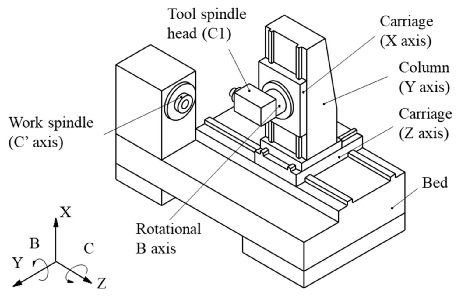
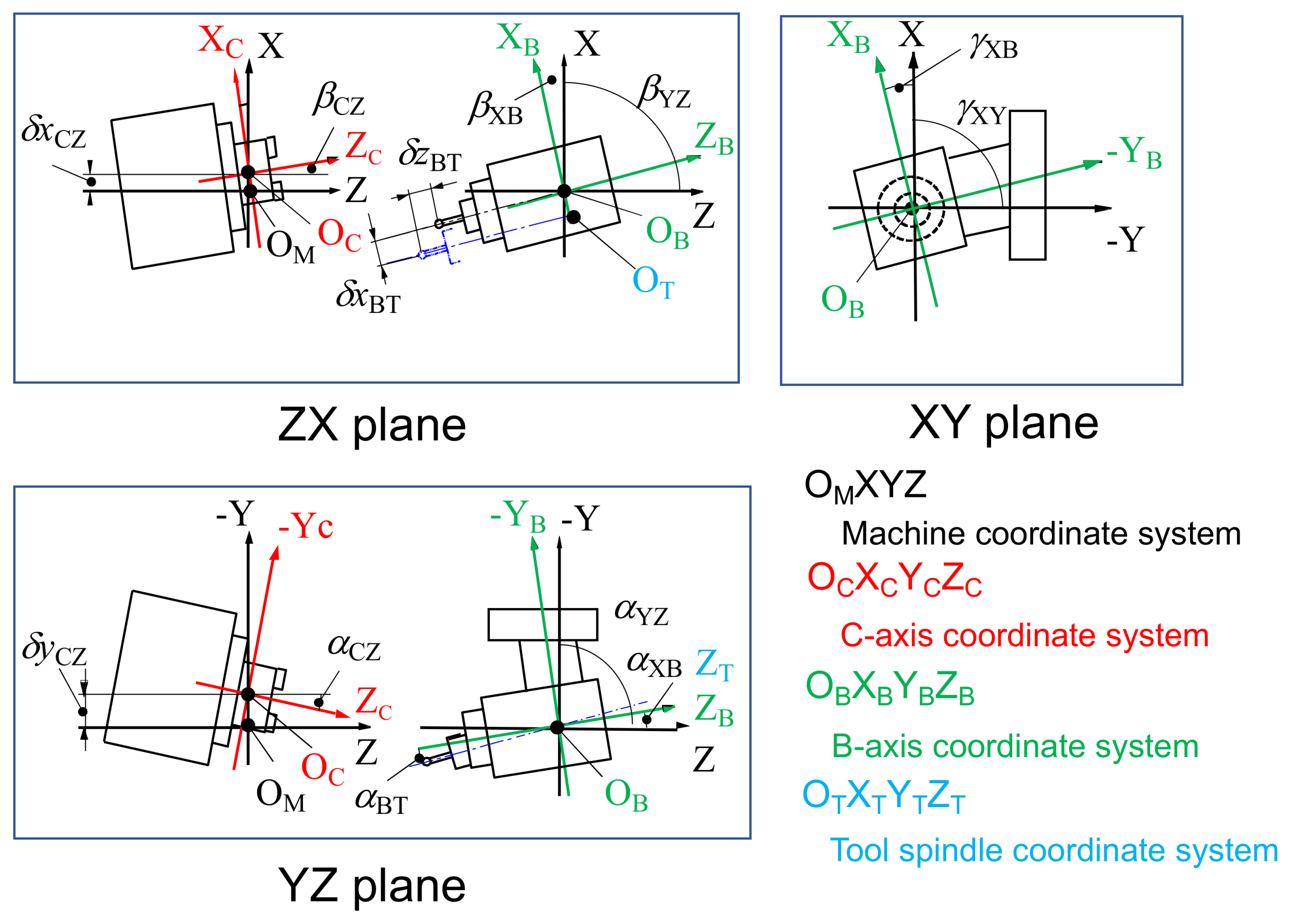
2. Coordinate System and Geometric Deviations of Multi-Tasking Machine Tools

Figure 1 shows the schematic view of a multi-tasking machine tool with a swivel tool spindle head in horizontal position. The structural configuration of this multi-tasking machine tool can be expressed as w-C’bZYXB (C1)-t if it is displayed from the work spindle side (w) to the tool spindle side (t), through the bed (b).
Although there are five controlled axes in the multi-tasking machine tools, the number of geometric deviations is different from that of five-axis machining centers according to the axis configuration and the mutual motion of the axes. Figure 2 shows the geometric deviations and the relation of each axis of the considered machine. Based on the theory of form-shaping system for machine tools [33], the negligible deviations of each axis are deleted from the possible deviations in order from ① to ⑤ shown in Figure 2. Therefore, there are 10 geometric deviations related with two axes of rotation—B and C axes, and three geometric deviations between three translational axes—X, Y, and Z axes, which should be identified to improve the motion accuracy of multi-tasking machine tools. In Figure 2, δx, δy, and δz represent the positional deviations in X-, Y-, and Z-direction, respectively. Similarly, α, β, and γ represent the angular deviations around X-, Y- and Z-axis, respectively. The large suffixes indicate two neighboring axes. For example, δxBT presents the positional deviation in X-direction of the tool spindle axis of rotation with respect to B axis origin. The variable αBT presents the squareness error of B axis with respect to the tool spindle axis of rotation about X axis.
The definitions of thirteen geometric deviations are summarized in Table 1 and illustrated in Figure 3. There are four coordinate systems, which are machine coordinate system (OM-XYZ), B axis coordinate system (OB-XBYBZB), C axis coordinate system (OC-XCYCZC) and tool spindle axis coordinate system (OT-XTYTZT). The machine coordinate system is defined as the reference system, whose origin is the intersection of the rotational center of B axis and the rotational center of C axis when the geometric deviations are all zero and the command values for each axis are set to its initial values. Since B axis and C axis are not directly connected, the upper surface of the C axis table is set as the origin of the machine coordinate system for the convenience.

3. Simultaneous Three-Axis Control Movements and Mathematical Model

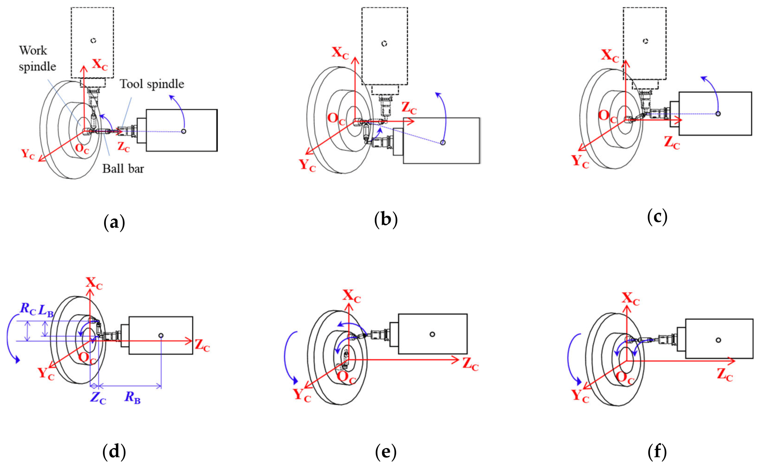
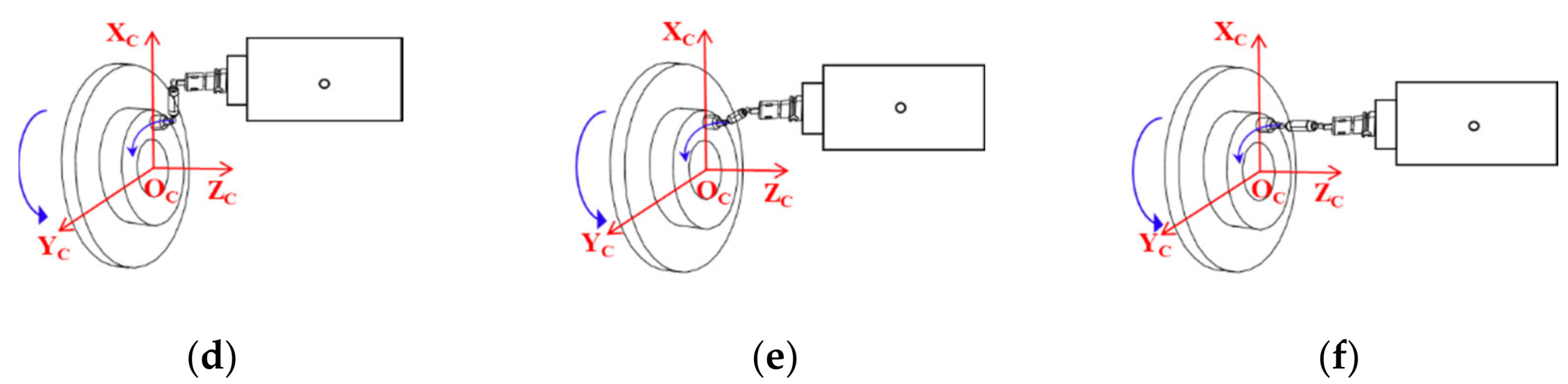
3.1. Simultaneous Three-Axis Control Movements

Simultaneous three-axis control movements which include two linear axes and one rotary axis can be conducted by means of the ball bar both in cylindrical coordinate system and in Cartesian coordinate system. The motions are named according to the sensitive direction of the ball bar as radial direction, tangential direction, axial direction in cylindrical coordinate system, illustrated in Figure 4, and X-, Y- and Z-direction in Cartesian coordinate system, illustrated in Figure 5.

3.2. Mathematical Model

Since the angular deviations are generally less than 1°, the small angle approximation ( sin θ θ cos θ 1 , if the angle θ < 0.244   radians   ( 14 ° ) , the relative error does not exceed 1%) is assumed and second order errors are neglected. Moreover, for small rotation matrices, the order of rotation matrix could be interchanged and it is possible to add and subtract matrices. Therefore, according to this minute rotation approximation theory, homogeneous transformation matrix (HTM) can be simplified in the mathematical model to express the center coordinates of both the tool spindle side ball (T-side ball) and the work spindle side ball (W-side ball) viewed from the machine coordinate system.

3.2.1. Determination of Center Coordinate T of the T-Side Ball Viewed from the Machine Coordinate System

When the distance from the rotational center of B axis to the center of the T-side ball is RB, the center coordinates TT of the T-side ball in the tool spindle axis coordinate system are expressed by Equation (1).
T T = [ 0 0 R B 1 ] T
As there are angular deviation αBT and positional deviations δxBT, δzBT between B axis and the tool spindle axis, the homogeneous transformation matrix M BT   from the tool spindle axis coordinate system to the B axis coordinate system is expressed by Equation (2) if the above simplified homogeneous coordinate transformation is used.
M BT = [ 1 0 0 1 0 δ x BT α BT 0 0 α BT 0 0       1         δ z BT 0 1 ]
In the same way, the homogeneous transformation matrix M XB between the X axis and B axis is defined as following.
M XB = [ 1 γ XB         γ XB 1 β XB 0 α XB 0 β XB α XB 0 0       1           0 0           1 ]
The T-side ball circularly moves around the B axis with radius RB. The circular motion of the T-side ball is expressed by the transformation matrix EB shown in Equation (4), using the rotation angle φ of the B axis.
E B = [     cos 0 0   1   sin 0 0 0 sin 0 0 0 cos 0 0 1 ]
The squareness of the X, Y and Z translational axes can be expressed by the homogeneous transformation matrix M YZ and M XY based on the theory of form-shaping system, as followings.
M YZ = [           1 0           0 1     β YZ 0 α YZ 0 β YZ α YZ 0 0       1 0       0 1 ]
M XY = [ 1 γ XY γ XY     1     0 0 0 0       0             0 0             0 1 0 0 1 ]
If the translational motion controlled by the command values of X, Y and Z axis is respectively expressed by EX, EY and EZ, the center coordinate of the T-side ball viewed from the machine coordinate system is denoted as following.
T = E Z M YZ E Y M XY E X M XB E B M BT T T

3.2.2. Determination of Center Coordinate W of the W-Side Ball Viewed from the Machine Coordinate System

If the initial position of the center coordinate of the W-side ball in the C axis coordinate system is W C   ( x w C , y w C , z w C ), the center coordinates W of the W-side ball viewed from the machine coordinate system are calculated as following.
The homogeneous transformation matrix M CZ between the C axis and Z axis is expressed by Equation (8).
M CZ = [ 1             0 0             1 β CZ δ x CZ α CZ δ y CZ β CZ α CZ 0 0 1           0 0           1 ]
The rotation of C axis around Z axis is defined by the transformation matrix E C   when the rotation angle θ   of the C axis is used.
E C = [ cos θ sin θ sin θ cos θ 0 0 0 0 0                 0 0                 0 1 0 0 1 ]
Therefore, the center coordinate W of the W-side ball viewed from the machine coordinate system is denoted as following.
W = M CZ E C W C

3.2.3. Determination of the Initial Position W C of Center Coordinate of the W-Side Ball

The W-side ball is positioned based on the center coordinate of the T-side ball, so it is necessary to add the influence of geometric deviations to the initial position of the W-side ball.
The mounting position W C of the W-side ball in the machine coordinate system is same with the center coordinate T of the T-side ball in the machine coordinate system. Further, the initial position of the W-side ball is decided only by the command values of the translational axes without the B axis rotation. Therefore, it can be calculated by removing E B from the Equation (7), expressed as the following Equations (11) and (12) for setup of the B and C axes measurements, respectively.
When W-side ball is set for the B axis measurement,
W C = [ 1 0 0 1 0 0 0               0 0 0 0 0 1 Z C + R B 0 1 ] [ 1 γ X Y γ X Y 1 β Y Z 0 α Y Z 0 β Y Z α Y Z 0 0       1 0       0 1 ] [ 1 0 0 1 0 0 0 0 0 0 0 0 1 0 0 1 ] [ 1         γ XB γ XB   1 β XB δ x BT α XB α BT 0 β XB α XB + α BT 0 0                 1 δ z BT 0 1 ] [ 0 0 R B 1 ]
When W-side ball is set for the C axis measurement,
W C = [ 1 0 0 1 0 0 0               0 0 0 0 0 1 Z C + R B 0 1 ] [ 1 γ X Y γ X Y 1 β Y Z 0 α Y Z 0 β Y Z α Y Z 0 0       1 0       0 1 ] [ 1 0 0 1 0 R C 0 0 0 0 0 0 1 0 0 1 ] [ 1         γ XB γ XB   1 β XB δ x BT α XB α BT 0 β XB α XB + α BT 0 0                 1 δ z BT 0 1 ] [ 0 0 R B 1 ]
The transformation matrix from the machine coordinate system to the C axis coordinate system is performed by the inverse transformation of Equation (8). Moreover, when the W-side ball is mounted, the command value of the C axis is zero, so there is no need to consider the C axis rotation in the Equation (10). Therefore, the conversion from W C to W C   is expressed by Equation (13).
W C = [ 1             0 0             1 β CZ δ x CZ α CZ δ y CZ β CZ α CZ     0     0 1               0 0               1 ] W C

3.2.4. Calculation of the Difference ∆L between Reference Length and Measured Length of Ball Bar

From the above equations, the relative distance L between the T-side ball and the W-side ball can be calculated by the center coordinate T ( x t , y t , z t ) of the T-side ball and the center coordinate W ( x w , y w , z w   ) of the W-side ball when a command value is given to each axis. The relative distance L is different from the reference length L B of the ball bar because of the existence of geometric deviations in the multi-tasking machine tools. Therefore, the ball bar length change amount ∆L can be obtained from the relative distance L by subtracting the ball bar reference length L B   as written in Equation (14).
Δ L = ( x t x w ) 2 + ( y t y w ) 2 + ( z t z w ) 2 L B

4. Simulation

Influence of each deviation on the eccentricity is investigated by using the above mathematical model. The commands separately given to each axis during simulation are shown in Table 2.
The simulation of the simultaneous three-axis control movements is conducted at the condition of LB = 100 mm, ZC = 100 mm, RB = 200 mm, RC = 50 mm. ±0.005 degrees and ±20 μm are given as angular deviations and positional deviations, respectively. Then, simulation results are obtained as shown in Table 3. The dotted circle represents theoretical trajectory when there is no geometric deviation and the red or blue one represents changed trajectory affecting by geometric deviations. The figures show that if only one of the thirteen geometric deviations exist, the red or blue circular trajectory will appear and reflect the effect of the given deviation on the eccentricity. The blank part shows that there is no influence of the geometric deviation on trajectory. For example, for B axis radial direction measurement, when a value of +20 μm is given to δxBT while other twelve geometric deviations are all zero, eccentricity of trajectory occurs in -X axis direction. On the contrary, when a value of −20 μm is given to δxBT, eccentricity of trajectory occurs in +X axis direction.
The eccentricities occur by the following three reasons.
  • The position of trajectory center is changed; for example, the effect of δxBT on eccentricity in case of the B axis radial measurement.
  • The size of trajectory radius is changed; for example, the effect of δzBT on eccentricity in case of the B axis radial measurement.
  • The shape of trajectory is changed; for example, the effect of βYZ on eccentricity in case of the B axis radial measurement.

4.1. Influence of Mounting Errors of Ball Bar on Circular Trajectories

Considering the influence of mounting errors of the T-side ball, the center offset of the T-side ball (xT, yT, zT) with respect to the tool spindle axis is added to the initial center coordinate T T in the Equation (1), expressed as the following Equation (15). In the same way, the center offset of the W-side ball (xW, yW, zW) with respect to the C axis origin is added to the initial center coordinate W C in the Equation (13), expressed as the following Equation (16). The simulation is performed in two coordinate systems at the condition that the offset is 20 μm and the obtained results are shown in Table 4.
T T = [ x T y T z T 0 ] + [ 0 0 R B 1 ]
W C = [ x W y W z W 0 ] + [ 1             0 0             1 β CZ δ x CZ α CZ δ y CZ β CZ α CZ     0     0 1               0 0               1 ] W C
In Table 4, a dotted circle represents theoretical trajectory when there is no mounting errors of ball bar and the red circle represents changed trajectory affecting by one mounting error for each measurement. The blank indicates the trajectory has not changed. It is found that the eccentricity of circular trajectories in these two coordinate systems are strongly affected by the mounting errors of the T-side ball. Therefore, it is crucial to coincide the center of the T-side ball to the tool spindle before conducting measurements. However, the mounting errors of the W-side ball do not affect the eccentricity in Cartesian coordinate system for the B axis measurements, and in cylindrical coordinate system for the C axis measurements. Therefore, to eliminate the influence of mounting errors of the W-side ball on the eccentricities of circular trajectories, the B axis measurements in Cartesian coordinate system and C axis measurements in cylindrical coordinate system are proposed to identify the geometric deviations of multi-tasking machine tools.

4.2. Influence of Squareness of Translational Axes

The influence of squareness deviations of translational axes, αYZ, βYZ, and γXY, on the eccentricity of circular trajectories are shown at the last three columns in Table 3. It is observed that the squareness deviation γXY only affect the eccentricity of circular trajectory in case of the C axis Y-direction measurement in Cartesian coordinate system. Therefore, it is indispensable to conduct C axis Y-direction measurement for identifying the squareness deviations γXY. However, measurement accuracy of the eccentricity for the C axis Y-direction is strongly affected by the mounting errors of W-side ball and T-side ball, shown in Table 4. Besides, γXY is very small theoretically and it is difficult to identify γXY correctly by my proposed identification method. Therefore, the identification for γXY will not be researched in this study.

5. Identification Procedures and Validity

5.1. Mathematical Expressions between Eccentricities and Geometric Deviations

Mathematical expressions between eccentricities of circular trajectories and geometric deviations are summarized in Table 5 according to the simulation results. ex, ey and ez represent the components of eccentricities in X-, Y- and Z-direction, respectively. The subscripts indicate the type of measurements, for example, CA and BY represent measurements of the C axis axial direction and B axis Y- direction, respectively. Among the eccentricity, the positional deviation appears as eccentricity is, while the angular deviation, multiplied by coefficient ZC, RB or RC, appears in eccentricity. The deviation is positive if the direction of the deviation is identical with the direction of the eccentricity. On the contrary, the deviation is negative.
It is found that the expressions of the C axis tangential measurement have only opposite arithmetic signs comparing to those of the C axis radial measurement, and the expressions of the B axis X-direction measurement is similar with those of the B axis Z-direction measurement. Furthermore, it has been known that a pitch error of the worm gear affects the eccentricity of circular trajectory measured in the tangential direction. Thus, the C axis tangential measurement and B axis Z-direction measurement are not discussed to identify geometric deviations in this study.
In summary, considering the squareness of translational axes, twelve geometric deviations for multi-tasking machine tools can be identified by measuring the eccentricities of circular trajectories of the B axis X-direction, B axis Y-direction, C axis radial direction and C axis axial direction.

5.2. Formulae Considering Squareness of Translational Axes to Calculate Geometric Deviations

To determine 12 variables from eight expressions obtained from above four sensitive direction measurements, measurement conditions should be devised as following.
Firstly, as only one geometric deviation affects the X axis component of eccentricity in the B axis X-direction and Y-direction measurements, two deviations γXB and δzBT are directly identified based on the corresponding eccentricities measured from the B axis X-direction and Y-direction, expressed as Equations (17) and (18).
γ XB = e x BY R B
δ z BT = e x BX
Secondly, when the distance between the center of the W-side ball and the workbench surface of the C axis is changed from Z C to Z C , new eccentricities e x CR and e y CR are obtained by measuring the radial direction of the C axis again. Then, another six geometric deviations δxCZ, βCZ, βYZ, αCZ, αYZ and αXB are calculated by the following Equations (19)–(24).
δ x CZ = e x CR + e z BX Z C ( e x CR e x CR ) Z C Z C
β CZ = e x CR e x CR Z C Z C
β YZ = e x CR e x CR Z C Z C e x CA R C
α CZ = e y CR e y CR Z C Z C
α YZ = e y CR e y CR Z C Z C + e y CA R C
α XB = e z BY R B e y CA R C e y CR e y CR Z C Z C
Thirdly, when the radius value is changed from R B to R B , new eccentricities e x CR   and e y CR are obtained from the C axis radial measurement. The remaining deviations δxBT, βXB, αBT and δyCZ are calculated by the following Equations (25)–(28).
δ x BT = e z BX + R B ( e x CR e x CR ) R B R B .  
β XB = e x CR e x CR R B R B e x CR e x CR Z C Z C + e x CA R C .  
α BT = e y CR e y CR R B R B e z BY R B
δ y CZ = R B ( e y CR e y CR ) R B R B + Z C e y CR Z C e y CR Z C Z C

5.3. Measurement to Identify Geometric Deviations

To identify 12 geometric deviations based on the eccentricity of circular trajectory controlled by simultaneous three-axis motions, the following six measurements by means of the ball bar are indispensable, as shown in Figure 6.
Step 1: Four measurements, which are the B axis X-direction, B axis Y-direction, C axis axial direction and C axis radial direction, are conducted at the condition of LB, ZC and RB.
Step 2: The C axis radial measurement is conducted for the second time at the condition of LB, Z C and RB.
Step 3: The C axis radial measurement is conducted for the third time at the condition of LB, Z C and R B .
As a result, a ball bar measurement should be conducted once in the B axis X-direction, B axis Y-direction, C axis axial direction, and three times in C axis radial direction. After that, including the squareness of translational axes, 12 geometric deviations can be calculated by Equations (17)–(28).

5.4. Validity of the Proposed Identification Method

Numerical experiments are performed to confirm the validity of the formulae for geometric deviations. At first, by using a random number table, the initial values of geometric deviations are selected and substituted into the mathematical model. Six numerical experiments are conducted at R C   = 50 mm, R B   = 360 mm, R B = 410 mm, Z C = 300 mm and Z C = 340 mm. Table 6 summarizes the eccentricities obtained at each measurement. Finally, the eccentricities are substituted into the above formulae to calculate the geometric deviations. The differences between the initial values and the identified values are shown in Table 7.
From the results, it is found that the difference of angular deviations is less than 0.12 arcsecond and the difference of positional deviations is smaller than 0.37 µm. Therefore, 12 geometric deviations of multi-tasking machine tools, including the squareness deviations, αYZ and βYZ, can be identified correctly by using the above formulae.

6. Conclusions

In this paper, a method to identify geometric deviations which exist in multi-tasking machine tools on the basis of the trajectories of simultaneous three-axis control motions is investigated. The proposed method is applied to a multi-tasking machine tool with a swivel tool spindle head in horizontal position and the identification of the deviations is carried out. From the numerical experiments, the validity of the proposed identification method is clarified. Conclusions are summarized as following.
(1)
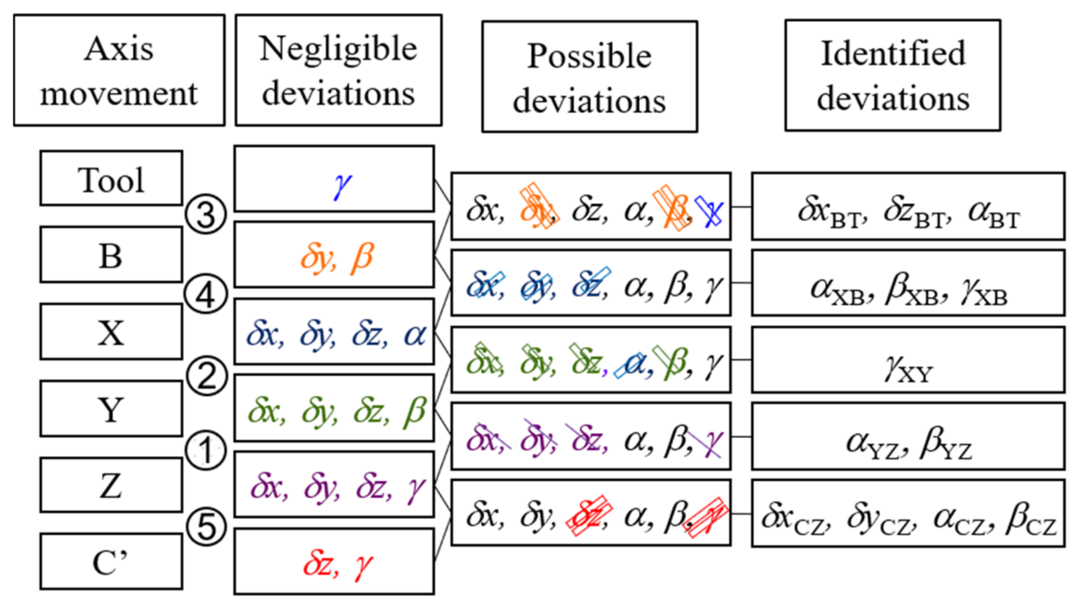
The identification method for 12 geometric deviations, in which two squareness deviations of translational axes αYZ and βYZ are included, is proposed.
(2)
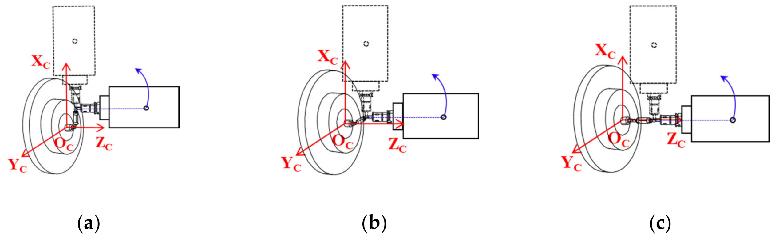
From the simulation results, it is confirmed that in order to eliminate the influence of the mounting errors of the W-side ball on the eccentricities of the circular trajectories, measurements for the B axis should be performed in Cartesian coordinate system and those for the C axis should be performed in cylindrical coordinate system.
(3)
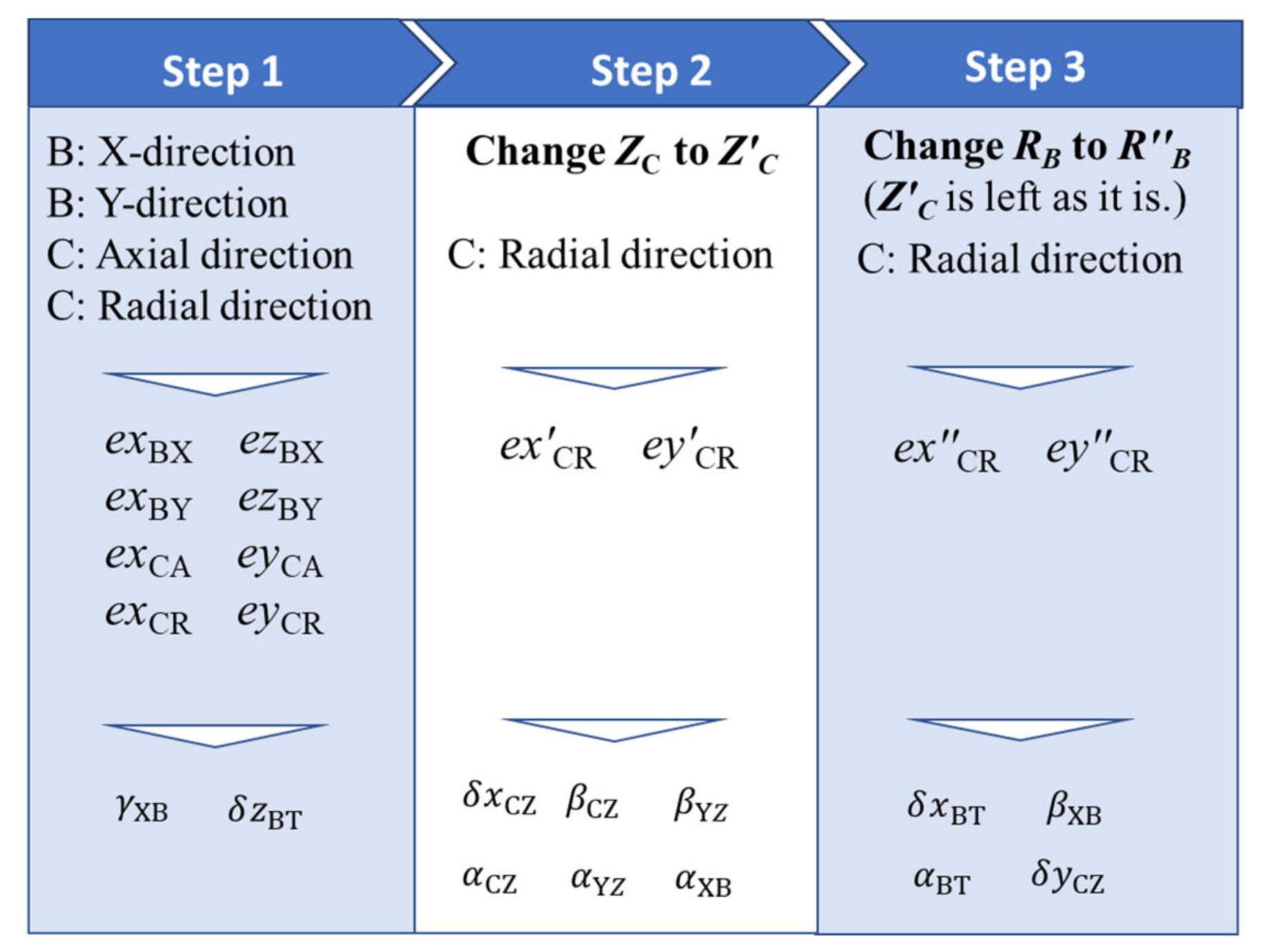
Considering the squareness of translational axes, six measurements by means of the ball bar are necessary to identify twelve geometric deviations.
(4)
The results of numerical experiments agree well with the given intentional deviations. Therefore, the influence of the analysis accuracy of the formulae on the identification could be considered to be negligible.
It can be concluded that the proposed identification method and the measurement procedure can be sufficiently utilized to identify geometric deviations for multi-tasking machine tools, in which the squareness of translational axes is taken into consideration.
At the next stage, the validity of the proposed method will be verified by an actual measurement of a multi-tasking machine tool. According to the proposed identification method, six measurements by using a ball bar will be conducted firstly and the eccentricities in each translational axis are obtained. Then, 12 geometric deviations of the considered machine tool will be calculated based on the formulae proposed in this paper. Finally, the measurements by a ball bar will be conducted again with compensation of deviations. If the eccentricities would disappear after the compensation, it can be concluded that the proposed method is effective to identify the geometric deviations accurately for multi-tasking machine tools.

Author Contributions

Conceptualization, M.T. and K.N. (Keiichi Nakamoto); methodology, N.K. and M.T.; software, N.K., K.N. (Keisuke Nishizawa) and Y.Y.; validation, M.T. and K.N. (Keisuke Nishizawa); formal analysis, Y.Y. and K.N. (Keisuke Nishizawa); investigation, K.N. (Keisuke Nishizawa) and Y.Y.; resources, K.N. (Keiichi Nakamoto); data curation, N.K., K.N. (Keisuke Nishizawa) and Y.Y.; writing—original draft preparation, Y.Y.; writing—review and editing, K.N. (Keiichi Nakamoto) and M.T.; visualization, Y.Y. and M.T.; supervision, K.N. (Keiichi Nakamoto) and M.T.; project administration, K.N. (Keiichi Nakamoto); funding acquisition, K.N. (Keiichi Nakamoto). All authors have read and agreed to the published version of the manuscript.

Funding

This research received no external funding.

Conflicts of Interest

The authors declare no conflict of interest. The funders had no role in the design of the study; in the collection, analyses, or interpretation of data; in the writing of the manuscript, or in the decision to publish the results.

References

  1. Álvarez, Á.; Calleja, A.; Ortega, N.; De Lacalle, L. Five-Axis Milling of Large Spiral Bevel Gears: Toolpath Definition, Finishing, and Shape Errors. Metals 2018, 8, 353. [Google Scholar] [CrossRef] [Green Version]
  2. Calleja, A.; Bo, P.; González, H.; Bartoň, M.; De Lacalle, L.N.L. Highly accurate 5-axis flank CNC machining with conical tools. Int. J. Adv. Manuf. Technol. 2018, 97, 1605–1615. [Google Scholar] [CrossRef] [Green Version]
  3. Bo, P.; Bartoň, M.; Plakhotnik, D.; Pottmann, H. Towards efficient 5-axis flank CNC machining of free-form surfaces via fitting envelopes of surfaces of revolution. Comput. Aided Des. 2016, 79, 1–11. [Google Scholar] [CrossRef] [Green Version]
  4. Calleja, A.; Gonzalez Barrio, H.; Polvorosa Teijeiro, R.; De Lacalle Marcaide, L.N.L. MÁQUINAS MULTITAREA: EVOLUCIÓN, RECURSOS, PROCESOS Y PROGRAMACIÓN. DYNAII 2017, 92, 637–642. [Google Scholar] [CrossRef] [Green Version]
  5. Gomez-Acedo, E.; Olarra, A.; Orive, J.; De Lacalle, L.N.L. Methodology for the design of a thermal distortion compensation for large machine tools based in state-space representation with Kalman filter. Int. J. Mach. Tools Manuf. 2013, 75, 100–108. [Google Scholar] [CrossRef]
  6. Pelayo, G.U.; Olvera, D.; De Lacalle, L.N.L.; Beranoagirre, A.; Elías-Zúñiga, A.; De Lacalle, L.N.L. Prediction Methods and Experimental Techniques for Chatter Avoidance in Turning Systems: A Review. Appl. Sci. 2019, 9, 4718. [Google Scholar]
  7. Olvera, D.; De Lacalle, L.N.L.; Compeán, F.I.; Fz-Valdivielso, A.; Lamikiz, A.; Campa, F.J. Analysis of the tool tip radial stiffness of turn-milling centers. Int. J. Adv. Manuf. Technol. 2012, 60, 883–891. [Google Scholar] [CrossRef]
  8. Zargarbashi, S.H.H.; Mayer, J.R.R. Assessment of machine tool trunnion axis motion error, using magnetic double ball bar. Int. J. Mach. Tools Manuf. 2006, 46, 1823–1834. [Google Scholar] [CrossRef]
  9. Lei, W.T.; Paung, I.M.; Yu, C.-C. Total ballbar dynamic tests for five-axis CNC machine tools. Int. J. Mach. Tools Manuf. 2009, 49, 488–499. [Google Scholar] [CrossRef]
  10. Lei, W.T.; Sung, M.P.; Liu, W.L.; Chuang, Y.C. Double ballbar test for the rotary axes of five-axis CNC machine tools. Int. J. Mach. Tools Manuf. 2007, 47, 273–285. [Google Scholar] [CrossRef]
  11. Tsutsumi, M.; Saito, A. Identification and compensation of systematic deviations particular to 5-axis machining centers. Int. J. Mach. Tools Manuf. 2003, 43, 771–780. [Google Scholar] [CrossRef]
  12. Tsutsumi, M.; Saito, A. Identification of angular and positional deviations inherent to 5-axis machining centers with a tilting-rotary table by simultaneous four-axis control movements. Int. J. Mach. Tools Manuf. 2004, 44, 1333–1342. [Google Scholar] [CrossRef]
  13. Tsutsumi, M.; Tone, S.; Kato, N.; Sato, R. Enhancement of geometric accuracy of five-axis machining centers based on identification and compensation of geometric deviations. Int. J. Mach. Tools Manuf. 2013, 68, 11–20. [Google Scholar] [CrossRef]
  14. Tsutsumi, M.; Miyama, N.; Tone, S.; Saito, A.; Cui, C.; Dasssanayake, K.M. Correction of Squareness of Translational Axes for Identification of Geometric Deviations Inherent to Five-Axis Machining Centres with a Tilting-Rotary Table. Trans. Jpn. Soc. Mech. Eng. Ser. C 2013, 79, 759–774. [Google Scholar] [CrossRef]
  15. Lee, K.-I.; Yang, S.-H. Measurement and verification of position-independent geometric errors of a five-axis machine tool using a double ball-bar. Int. J. Mach. Tools Manuf. 2013, 70, 45–52. [Google Scholar] [CrossRef]
  16. Xiang, S.; Deng, M.; Li, H.; Du, Z.; Yang, J. Volumetric error compensation model for five-axis machine tools considering effects of rotation tool center point. Int. J. Adv. Manuf. Technol. 2019, 102, 4371–4382. [Google Scholar] [CrossRef]
  17. Yang, J.; Ding, H. A new position independent geometric errors identification model of five-axis serial machine tools based on differential motion matrices. Int. J. Mach. Tools Manuf. 2016, 104, 68–77. [Google Scholar] [CrossRef]
  18. Chen, J.; Lin, S.; He, B. Geometric error measurement and identification for rotary table of multi-axis machine tool using double ballbar. Int. J. Mach. Tools Manuf. 2014, 77, 47–55. [Google Scholar] [CrossRef]
  19. Dassanayake, K.M.M.; Tsutsumi, M.; Saito, A. A strategy for identifying static deviations in universal spindle head type multi-axis machining centers. Int. J. Mach. Tools Manuf. 2006, 46, 1097–1106. [Google Scholar] [CrossRef]
  20. Li, J.; Mei, B.; Shuai, C.; Liu, X.; Liu, D. A volumetric positioning error compensation method for five-axis machine tools. Int. J. Adv. Manuf. Technol. 2019, 103, 3979–3989. [Google Scholar] [CrossRef]
  21. Li, J.; Xie, F.; Liu, X.-J.; Dong, Z.; Song, Z.; Li, W. A geometric error identification method for the swiveling axes of five-axis machine tools by static R-test. Int. J. Adv. Manuf. Technol. 2017, 89, 3393–3405. [Google Scholar] [CrossRef]
  22. Ibaraki, S.; Sawada, M.; Matsubara, A.; Matsushita, T. Machining tests to identify kinematic errors on five-axis machine tools. Precis. Eng. 2010, 34, 387–398. [Google Scholar] [CrossRef] [Green Version]
  23. Uddin, M.S.; Ibaraki, S.; Matsubara, A.; Matsushita, T. Prediction and compensation of machining geometric errors of five-axis machining centers with kinematic errors. Precis. Eng. 2009, 33, 194–201. [Google Scholar] [CrossRef] [Green Version]
  24. Ibaraki, S.; Yoshida, I. A Five-Axis Machining Error Simulator for Rotary-Axis Geometric Errors Using Commercial Machining Simulation Software. Int. J. Autom. Technol. 2017, 11, 179–187. [Google Scholar] [CrossRef]
  25. Ibaraki, S.; Nagai, Y.; Otsubo, H.; Sakai, Y.; Morimoto, S.; Miyazaki, Y. R-Test Analysis Software for Error Calibration of Five-Axis Machine Tools—Application to a Five-Axis Machine Tool with Two Rotary Axes on the Tool Side. Int. J. Autom. Technol. 2015, 9, 387–395. [Google Scholar] [CrossRef]
  26. Hong, C.; Ibaraki, S. Observation of Thermal Influence on Error Motions of Rotary Axes on a Five-Axis Machine Tool by Static R-Test. Int. J. Autom. Technol. 2012, 6, 196–204. [Google Scholar] [CrossRef]
  27. Hong, C.; Ibaraki, S.; Oyama, C. Graphical presentation of error motions of rotary axes on a five-axis machine tool by static R-test with separating the influence of squareness errors of linear axes. Int. J. Mach. Tools Manuf. 2012, 59, 24–33. [Google Scholar] [CrossRef]
  28. Ibaraki, S.; Oyama, C.; Otsubo, H. Construction of an error map of rotary axes on a five-axis machining center by static R-test. Int. J. Mach. Tools Manuf. 2011, 51, 190–200. [Google Scholar] [CrossRef] [Green Version]
  29. Ibaraki, S.; Ota, Y. Error Calibration for Five-Axis Machine Tools by On-the-Machine Measurement Using a Touch-Trigger Probe. Int. J. Autom. Technol. 2014, 8, 20–27. [Google Scholar] [CrossRef]
  30. Mayer, J.R.R. Five-axis machine tool calibration by probing a scale enriched reconfigurable uncalibrated master balls artefact. CIRP Ann. 2012, 61, 515–518. [Google Scholar] [CrossRef]
  31. Iñigo, B.; Ibabe, A.; Aguirre, G.; Urreta, H.; De Lacalle, L.N.L. Analysis of Laser Tracker-Based Volumetric Error Mapping Strategies for Large Machine Tools. Metals 2019, 9, 757. [Google Scholar] [CrossRef] [Green Version]
  32. Díaz-Tena, E.; Ugalde, U.; López de Lacalle, L.N.; De La Iglesia, A.; Calleja, A.; Campa, F.J. Propagation of assembly errors in multitasking machines by the homogenous matrix method. Int. J. Adv. Manuf. Technol. 2013, 68, 149–164. [Google Scholar] [CrossRef]
  33. Portman, V.; Inasaki, I.; Sakakura, M.; Iwatate, M. Form-Shaping Systems of Machine Tools: Theory and Applications. CIRP Ann. 1998, 47, 329–332. [Google Scholar] [CrossRef]
Figure 1. Schematic view of a multi-tasking machine tool with a swivel tool spindle head in horizontal position.
Applsci 10 01811 g001
Figure 2. Definition of geometric deviations according to the considered multi-tasking machine tool.
Applsci 10 01811 g002
Figure 3. Illustration of coordinate systems and geometric deviations.
Applsci 10 01811 g003
Figure 4. (a) B axis radial measurement; (b) B axis tangential measurement; (c) B axis axial measurement; (d) C axis radial measurement; (e) C axis tangential measurement; (f) C axis axial measurement.
Applsci 10 01811 g004
Figure 5. (a) B axis X-direction measurement; (b) B axis Y-direction measurement; (c) B axis Z-direction measurement; (d) C axis X-direction measurement; (e) C axis Y-direction measurement; (f) C axis Z-direction measurement.
Applsci 10 01811 g005aApplsci 10 01811 g005b
Figure 6. Measurement procedures to identify twelve geometric deviations.
Applsci 10 01811 g006
Table 1. Symbols of geometric deviations and descriptions.
SymbolDescription
δxBTX-direction offset of tool spindle axis of rotation with respect to B axis origin
δzBTZ-direction offset of tool spindle axis of rotation with respect to B axis origin
αBTSquareness error of B axis with respect to tool spindle axis of rotation about X axis
αXBSquareness error of B axis of rotation with respect to Z axis motion
βXBInitial angular position error of B axis of rotation with respect to X (Z) axis motion
γXBSquareness error of B axis of rotation with respect to X axis motion
γXYSquareness error between X axis motion and Y axis motion
αYZSquareness error between Y axis motion and Z axis motion
βYZSquareness error between Z axis motion and X axis motion
δxCZX-direction offset of C axis origin with respect to machine coordinate origin
δyCZY-direction offset of C axis origin with respect to machine coordinate origin
αCZParallelism error of C axis of rotation with respect to Z axis about X axis
βCZParallelism error of C axis of rotation with respect to Z axis about Y axis
Table 2. Commands given to each axis during simulation.
CylindricalB AxisC Axis
RadialTangentialAxialRadialTangentialAxial
Command X(LB + RB) sin φRBT sin (φ + tan−1LB/RB) aRB sin φ(RCLB) cos θRCT cos (θ + tan−1LB/RC) bRC cos θ
Command Y00LB(RCLB) sin θRCT sin (θ + tan1LB/RC) bRC sin θ
Command ZZC + (LB + RB) cos φZC + RBT cos (φ + tan−1LB/RB) aZC + RB cos φZC + RBZC + RBZC + LB + RB
Command Bφφφ000
Command C000θθθ
CartesianX-directionY-directionZ-directionX-directionY-directionZ-direction
Command XLB + RB sin φRB sin φRB sin φLB + RC cos θRC cos θRC cos θ
Command Y0LB0RC sin θLB + RC sin θRC sin θ
Command ZZC + RB cos φZC + RB cos φLB + ZC + RB cos φZC + RBZC + RBLB + ZC + RB
Command Bφφφ000
Command C000θθθ
a R BT = R B 2 + L B 2 ; b R CT = R C 2 + L B 2 .
Table 3. Effect of geometric deviations on the eccentricities of circular trajectories in cylindrical coordinate system and in Cartesian coordinate system.
δ x B T δ z B T α X B β X B γ X B α B T δ x C Z δ y C Z α C Z β C Z α Y Z β Y Z γ X Y
B axis Radial Applsci 10 01811 i001 Applsci 10 01811 i002 Applsci 10 01811 i003 Applsci 10 01811 i004
B axis Tangential Applsci 10 01811 i005 Applsci 10 01811 i006 Applsci 10 01811 i007 Applsci 10 01811 i008
B axis Axial Applsci 10 01811 i009 Applsci 10 01811 i010 Applsci 10 01811 i011
B axis
X-direction
Applsci 10 01811 i012 Applsci 10 01811 i013 Applsci 10 01811 i014 Applsci 10 01811 i015
B axis
Y-direction
Applsci 10 01811 i016 Applsci 10 01811 i017 Applsci 10 01811 i018
B axis
Z-direction
Applsci 10 01811 i019 Applsci 10 01811 i020 Applsci 10 01811 i021
C axis Radial Applsci 10 01811 i022 Applsci 10 01811 i023 Applsci 10 01811 i024 Applsci 10 01811 i025 Applsci 10 01811 i026 Applsci 10 01811 i027 Applsci 10 01811 i028 Applsci 10 01811 i029 Applsci 10 01811 i030 Applsci 10 01811 i031 Applsci 10 01811 i032
C axis Tangential Applsci 10 01811 i033 Applsci 10 01811 i034 Applsci 10 01811 i035 Applsci 10 01811 i036 Applsci 10 01811 i037 Applsci 10 01811 i038 Applsci 10 01811 i039 Applsci 10 01811 i040 Applsci 10 01811 i041 Applsci 10 01811 i042 Applsci 10 01811 i043
C axis Axial Applsci 10 01811 i044 Applsci 10 01811 i045 Applsci 10 01811 i046 Applsci 10 01811 i047
C axis
X-direction
Applsci 10 01811 i048 Applsci 10 01811 i049 Applsci 10 01811 i050 Applsci 10 01811 i051 Applsci 10 01811 i052 Applsci 10 01811 i053 Applsci 10 01811 i054 Applsci 10 01811 i055 Applsci 10 01811 i056 Applsci 10 01811 i057
C axis
Y-direction
Applsci 10 01811 i058 Applsci 10 01811 i059 Applsci 10 01811 i060 Applsci 10 01811 i061 Applsci 10 01811 i062 Applsci 10 01811 i063 Applsci 10 01811 i064 Applsci 10 01811 i065 Applsci 10 01811 i066 Applsci 10 01811 i067 Applsci 10 01811 i068
C axis
Z-direction
Applsci 10 01811 i069 Applsci 10 01811 i070 Applsci 10 01811 i071 Applsci 10 01811 i072
Applsci 10 01811 i073: +20 µm, +0.005°, Applsci 10 01811 i074: −20 µm, −0.005°, Blank: No influence.
Table 4. Influence of mounting errors of ball bar on the eccentricity of circular trajectories.
x W y W z W x T y T z T
Cylindrical coordinate systemB axis Radial Applsci 10 01811 i075 Applsci 10 01811 i076 Applsci 10 01811 i077 Applsci 10 01811 i078
B axis Tangential Applsci 10 01811 i079 Applsci 10 01811 i080 Applsci 10 01811 i081 Applsci 10 01811 i082
B axis Axial Applsci 10 01811 i083
Cartesian coordinate systemB axis
X-direction
Applsci 10 01811 i084 Applsci 10 01811 i085 Applsci 10 01811 i086
B axis
Y-direction
Applsci 10 01811 i087
B axis
Z-direction
Applsci 10 01811 i088 Applsci 10 01811 i089 Applsci 10 01811 i090
Cylindrical coordinate systemC axis Radial Applsci 10 01811 i091 Applsci 10 01811 i092 Applsci 10 01811 i093
C axis Tangential Applsci 10 01811 i094 Applsci 10 01811 i095 Applsci 10 01811 i096
C axis Axial Applsci 10 01811 i097
Cartesian coordinate systemC axis
X-direction
Applsci 10 01811 i098 Applsci 10 01811 i099 Applsci 10 01811 i100 Applsci 10 01811 i101
C axis
Y-direction
Applsci 10 01811 i102 Applsci 10 01811 i103 Applsci 10 01811 i104 Applsci 10 01811 i105
C axis
Z-direction
Applsci 10 01811 i106
Table 5. Mathematical expressions between eccentricities and geometric deviations.
exeyez
B: X-directionδzBTδxBT − RBβXB − RBβYZ
B: Y-direction−RBγXBRBαXB + RBαYZ
B: Z-directionRBβXB − δxBT δzBT
C: Radial−δxBT + RBβXB + δxCZ + ZCβCZ + RBβYZ−RBαXB − RBαBT + δyCZ − ZCαCZ − RBαYZ
C: TangentialRBαXB + RBαBT − δyCZ + ZCαCZ + RBαYZ−δxBT + RBβXB + δxCZ + ZCβCZ + RBβYZ
C: AxialRCβCZ − RCβYZRCαYZ − RCαCZ
Table 6. Eccentricities of circular trajectories in numerical experiments.
DirectionB Axis (μm)C Axis (μm)
X aY aAxial aRadial aRadial bRadial c
ex16.63−11.240.2925.7326.8928.97
ey--0.05−19.59−20−23.26
ez−4.0210.05----
a R B = 360 mm; Z C = 300 mm; b Z C = 340 mm; c R B = 410 mm.
Table 7. Difference between initial values and identified values.
Initial ValuesIdentified ValuesDifference
δxBT (µm)11.0010.96−0.04
δzBT (µm)17.0016.63−0.37
αBT (″)7.637.690.06
αXB (″)3.513.44−0.07
βXB (″)3.923.80−0.12
γXB (″)6.396.440.05
αYZ (″)2.272.320.05
βYZ (″)4.744.790.05
δxCZ (µm)13.0013.010.01
δyCZ (µm)7.006.96−0.04
αCZ (″)2.062.110.05
βCZ (″)5.985.980.00

