Article

Influence of Surroundings on Radiant Tube Lifetime in Indirect-Fired Vertical Strip Annealing Furnaces

Department for Industrial Furnaces and Heat Engineering, RWTH Aachen University, Kopernikusstraße 10, 52074 Aachen, Germany
*
Author to whom correspondence should be addressed.
Appl. Sci. 2020, 10(5), 1748; https://doi.org/10.3390/app10051748
Submission received: 20 December 2019 / Revised: 26 February 2020 / Accepted: 28 February 2020 / Published: 4 March 2020
(This article belongs to the Section Applied Industrial Technologies)

Abstract

:

Featured Application

Towards the development of a full-fledged model for the prediction of radiant tube lifetime in strip annealing furnaces, to serve its end-user through integration into the process-and control-strategies.

Abstract

The effects of surrounding radiation—emanating from radiation exchange with neighboring partners in indirect-fired vertical strip annealing furnaces, such as the other radiant tubes, the passing strip, and the enclosing furnace chamber—on the radiant tube lifetime were studied. In-house developed and validated numerical models were used to calculate the thermomechanical behavior, especially creep deformations and the corresponding stresses as lifetime indicating parameters. Different setups of recirculating P-type radiant tubes were investigated, including a reference case of an isolated tube. The investigations could be broadly classified into the study of the effects of different tube arrangements, burner operations (synchronous/asynchronous on/off firing), and changes of strip parameters (width/temperature). Results showed higher creep deformation of the central radiant tube in the setup with three tubes arranged horizontally in a row compared to three tubes stacked in a vertical column, even though the respective characteristic temperature values in a firing cycle were similar. Furthermore, the cases with asynchronous burner firing resulted in lower creep rates than other cases, where the burners were operating in synchronous on/off firing modes. In addition, the change of strip width had a higher impact on radiant tube lifetime compared to locally changing strip temperatures across the furnace. Alternating temperatures, caused by burner operation or process changes, such as change of strip’s speed or cross-section, and local temperature gradients were observed to be the main factors influencing the tube’s service life.

1. Introduction

In the steel industry, vertical strip galvanizing lines are used for the production of high-quality coated steel strips to be utilized, e.g., in making automotive body parts. The indirect-fired vertical strip annealing furnace in such a continuous strip galvanizing line (CGL) usually comprises of metallic radiant tubes (RT), arranged in several columns with the strip driven between them (Figure 1a). The furnace, commonly divided into heating and soaking sections, normally operates under a protective gas atmosphere to prevent oxidation of the steel strips. The radiant tubes serve the purpose of heating the steel strips and simultaneously separate the combustion gases from the protective gas atmosphere in the furnace.
The annealing furnace of a 450,000 tonnes/year galvanizing line, operating in thyssenkrupp Steel Europe GmbH in Dortmund since 2001, can be taken as a typical example (comparable to Figure 1b). The radiant tube heating section of this furnace is equipped with a total of 189 double-P-type radiant tubes, amounting to a total heat input of 27 MW [1]. An annual tube mortality rate of approx. 20% is a reasonable assumption for strip annealing furnaces [2,3]. At a typical cost of 7000 € for a single double-P-type radiant tube, direct tube replacement costs of approx. 260,000 € per annum could be expected for one such CGL alone. Additional costs of plant shutdowns and installation also need to be considered. Therefore, the potential for cost savings for several such CGLs justifies any effort to understand the factors influencing radiant tube lifetime. To this end, it is also important to develop reliable lifetime models not just to prevent radiant tube failures (Figure 2) but also to anticipate periods of service and change production recipes accordingly [4].
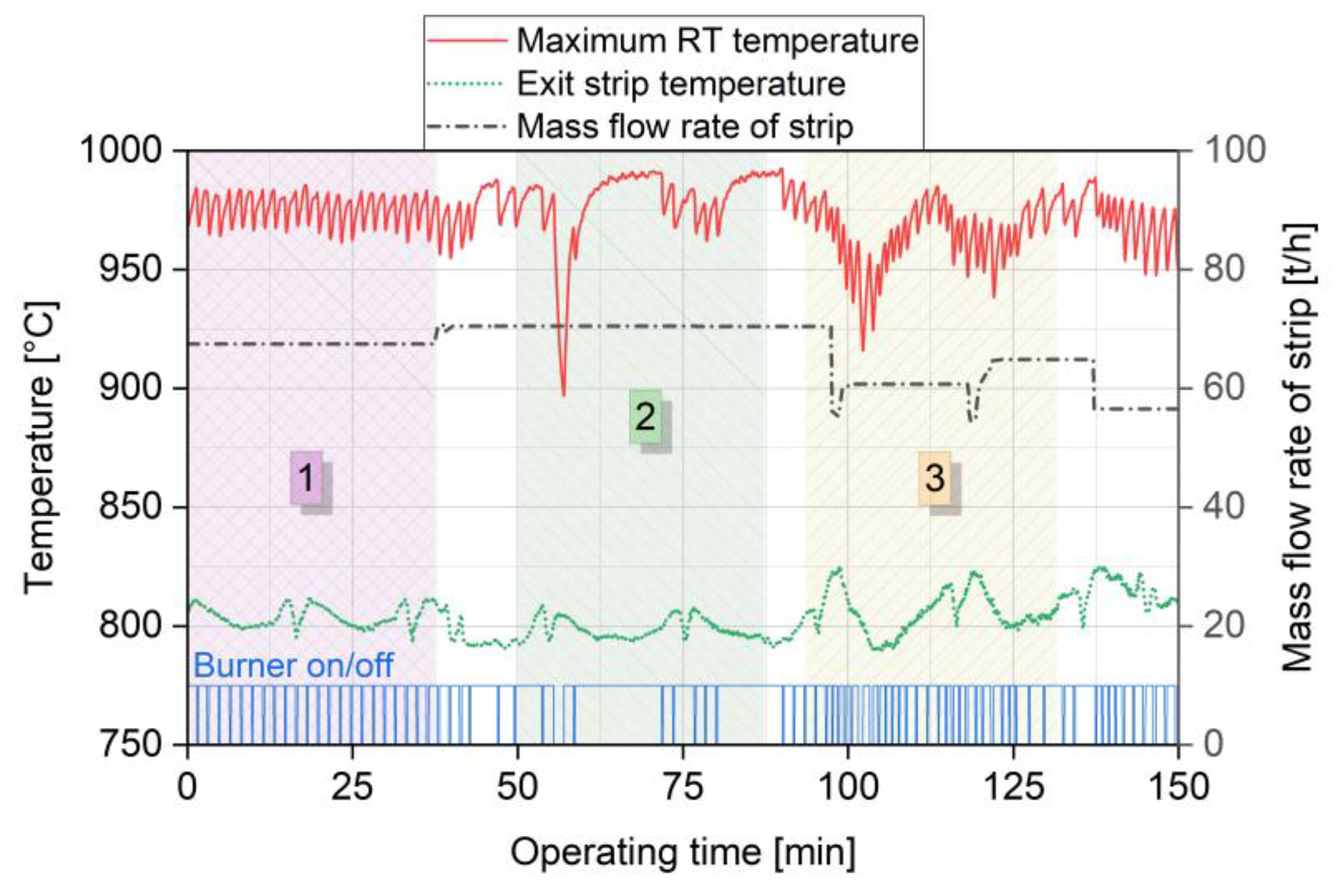
Radiant tube lifetime is influenced by its surroundings and their varying parameters resulting from process changes inherent in the operation of an annealing furnace of a CGL. The burners installed in recirculating radiant tubes are normally operated in on/off firing mode, in order to ensure better temperature uniformity on the tube as well as low NOx-emissions. The on-state corresponds to the burner operation at full-load (100% power). In temperature-controlled systems, the burner is switched to off-mode when a specified maximum temperature is reached. As soon as the temperature is too low, the burner is switched on again. Alternative furnace control systems operate based on the strip outlet temperature or the required energy input into the furnace. Model predictive control strategies can be used to anticipate the short term future process behavior and push the process towards its limits [5,6]. Additionally, a sequential firing logic is implemented into the furnace control system to set the burner on/off firing cycles for each radiant tube [7]. A radiant tube in a CGL furnace not only experiences cyclic thermal loading due to burner on/off firing but is also exposed to changes in temperatures arising from heat transfer (mainly radiative) to its neighboring tubes, the furnace chamber, and the passing strip. Figure 3 illustrates the influence of surroundings on the surface temperatures of a double-P-type radiant tube in an annealing furnace of a CGL for steel strips. The mass flow rate of strip is calculated as the product of the strip’s cross-section, its velocity magnitude, and its density, thus representing the change of strip parameters. Region 1 presents the classic case of tube temperatures under burner on/off operation, with firing cycle times of approx. 100 s. In contrast, Region 2 shows drastic changes in tube temperatures, even though no change in the mass flow rate of the strip (similar to Region 1) is observed. These changes can be attributed to the control strategy of the burners in this particular furnace zone, used to maintain the strip temperature at a defined level. Taking a closer look at Region 2, it is evident that the burner operates under full-load firing for large swathes of operating time. Region 3 delineates the standard case of change of tube temperatures due to variation in strip parameters. The process and control strategies of a particular furnace thus have a significant effect on the thermal loading of radiant tubes in a CGL furnace. In addition, the setups of the neighboring tubes in a CGL furnace play an important role in determining the local distribution of tube temperatures. Therefore, it becomes imperative to consider the effects of a radiant tube’s temperature changes caused by its surroundings in a CGL furnace under real operating conditions.

2. Status of Research and Objectives in Radiant Tube Lifetime Modeling

Limited advancements have been made in the last two decades in the context of simulations and experiments towards building a full-fledged model for prediction of radiant tube lifetime in CGL furnaces.

2.1. Microscopic Damage Analysis

On the one hand, microscopic damage analyses on radiant tubes were carried out with sample process temperatures and total process time as their primary parameters. Chakrabarti et al. [8] performed failure analysis of U-type radiant tubes, made of centrifugally cast Ni–Cr steels, in a CGL. Three root causes of failures were identified: high-temperature oxidation due to overheating of the tube (>1090 °C), hot spots created by supports, and possible uncontrolled combustion/explosion due to fluctuations in gas compositions. The failure of radiant tubes by high-temperature oxidization or carburization attacks were also confirmed by [9,10,11,12,13]. Another key finding of the microscopic analyses was radiant tube failures caused by high-temperature creep. Saravanan et al. [14] studied metallographically the damage of radiant tubes in a continuous annealing line (CAL) and found signs of the advanced stage of creep deformation. It was also suggested that severe creep deformation might have contributed towards the cracking of protective oxide scales and thus caused an accelerated corrosion attack. Zhu, et al. [15] confirmed that the root cause of failures in a CAL furnace was a high-temperature creep and added the importance of considering the effect of gravitational forces (dead weight of tube) into account. Palaniyandi et al. [16] supported this view and also pointed towards the role played by the tube temperature gradients during operation, such as during process changes, plant shutdown, or startups. The macroscopic thermomechanical behavior of the tube during the operation was not the subject of these investigations. Therefore, these studies—even though informative—are of limited value towards assessing the lifetime of radiant tubes in a CGL.

2.2. Early Macroscopic Studies

The macroscopic studies of radiant tubes, on the other hand, usually followed a one-dimensional approach in the early investigations. For instance, Tsioumanis et al. [17] built numerical models based on the finite volume method (FVM) for a single-ended radiant tube operating with a 25 kW self-recuperative burner. These models were validated against the flue gas compositions and the corresponding temperature measurements on the tube. Ahanj et al. [18] performed similar investigations and focussed on finding the optimum operating condition by determining the relationship between the burner air-ratio and the combustion efficiency of the radiant tube burner. Wang et al. [19] carried out simulations in the same way to study the effects of air staging on thermal and prompt NOx formation using validated FVM models. These and some recent studies [20,21,22] followed the same trend of ignoring the thermomechanical behavior of the radiant tube under operation. In contrast, Irfan and Chapman [23,24] investigated the thermomechanical stresses occurring in W-type radiant tubes using the finite element method (FEM) models. The tube temperature distributions were derived from experimental measurements instead of an FVM model. The results showed that the radial temperature gradients and local hot spots were major sources of the stresses in the tube. Also, the tube bends showed higher magnitudes of stress than the straight sections. Similar investigations were carried out by Dini et al. [25] on P-type radiant tubes of a CGL furnace. However, it is not practical to obtain experimental measurements for each radiant tube application. This makes the use of FVM models indispensable.

2.3. Recent Numerical Investigations

Hellenkamp et al. [26] and Schmitz et al. [27,28] performed the first studies on the thermomechanical behavior of radiant tubes using both the FVM and FEM models, thus forming a coupled fluid-structure-interaction (FSI) approach for radiant tube modeling. This FSI approach was validated with comprehensive temperature and flow measurements in a P-type radiant tube made of Alloy 602 with the burner operating at full-load. It was observed that an optimum geometry for a P-type radiant tube was one for which the R/D-ratio (radius of tube’s elbow to the outer diameter) was close to unity. This helped to minimize both the temperature differences and the thermal stresses acting on the tube. Recent investigations focussed on an FSI approach, taking the transient temperature changes in the radiant tube during operation into account. Caillat et al. [29], for example, carried out a coupled FSI analysis for W-type Ni–Cr cast radiant tubes operating in a CGL. The tube deformation and the stresses in the tube were calculated by using the Norton creep model for Ni–Cr alloys. The accuracy of the creep simulation was, however, not validated against deformation measurements on the tube. In addition, the effect of alternating temperatures during tube operation was neglected. Karthik et al. [30,31,32] developed the available FSI approach further to include the effects of cyclic thermal loading caused by temperature changes due to burner operation (e.g., on/off firing) or process changes (change of strip speed or cross-section), using the extended Graham–Walles creep model [33,34]. The investigations were validated against detailed integral and local deformation measurements on an Alloy 602 P-type radiant tube. The results showed an increase in creep deformation of the tube with an increase in the frequency of temperature changes for the same process time. The well-known phenomena of stress relaxation due to creep deformation were also confirmed in these studies.

2.4. Objectives of the Present Study

None of the previous investigations, however, took the effects of the tube’s radiation exchange with the surroundings on its thermomechanical behavior into account. The authors of the present work developed the first coupled heat transfer (CHT) model [35] to consider the effects of surrounding radiation on the lifetime of radiant tubes in a CGL, characterized by their creep deformation and corresponding thermomechanical stresses. The CHT model was validated against tube temperature measurements on a P-type radiant tube, operating with a 120 kW self-recuperative burner, in an in-house test bench. This model was used for P-type radiant tubes as extensive experimental data, and validations were available [27,28,30,31,32]. The steel strip, the neighboring tubes, and the remaining parts of the furnace incorporated as the furnace chamber were considered as the surroundings in the CHT model. The results showed an increase in creep deformation of the tube when the surroundings were considered. The highest creep deformations were observed for setups with a strip, even though these cases showed the lowest maximum tube temperatures. However, the results of this first CHT model were too simplistic as they did not involve assessing the effects of the complex furnace operation.
The present series of investigations was an extension of this CHT model. The case studies were performed for vertically-mounted P-type radiant tubes over a processing time of 400 h. The specific objectives of this work were:
  • To investigate the effects of the absence or presence of a (wide or narrow) strip with respect to a reference case of an isolated tube.
  • To demonstrate the influence of three different setups of the neighboring tube arrangement on a tube’s creep deformation and stresses.
  • To study the influence of the choice of burner operation (full-load firing, synchronous, and asynchronous on/off firing) on radiant tube lifetime.
  • To understand the effect of changing strip temperatures across an annealing furnace on the tube’s thermomechanical behavior.
  • To examine the correlation between the obtained creep deformation and thermomechanical stresses with the furnace operating conditions.

3. The Methodology of Numerical Modeling

3.1. Overview of the Models and Their Interactions

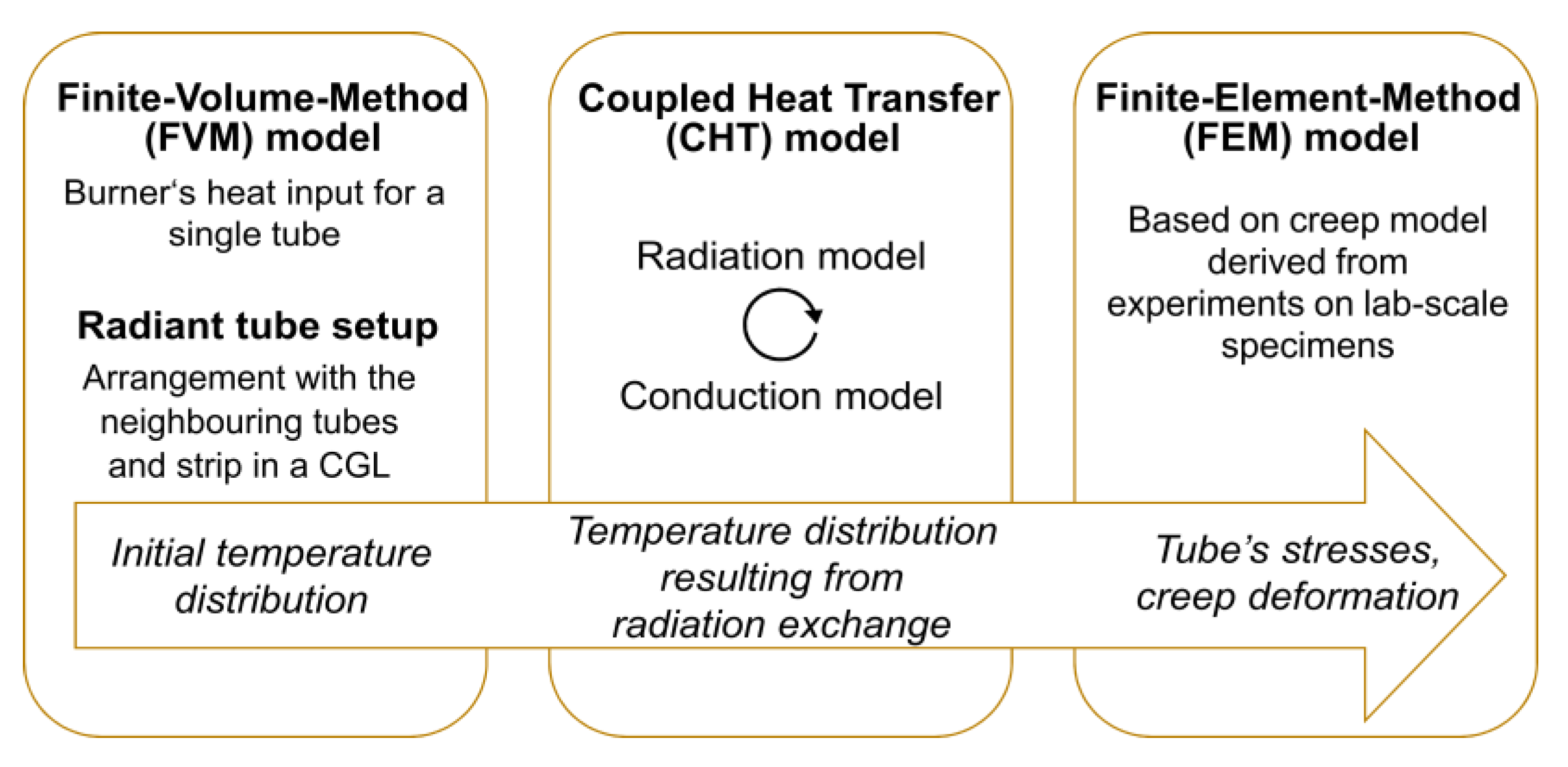
The heat transfer inside a CGL furnace is dominated by radiation and conduction. A developed CHT model was used to consider these two heat transfer mechanisms and determine their influence on the change in the tube’s temperature distributions due to its surroundings. Convection contributes marginally to the total heat transfer from the radiant tubes to the strip, accounting for around 5 to 10 percent (depending on the heat transfer coefficient) compared to radiative heat transfer. Therefore, the convective component of heat transfer was neglected in the CHT model. The CHT model was integrated into the previously mentioned FSI approach, developed by Karthik et al., as illustrated in Figure 4. The selected FSI approach followed a partitioned one-way coupling between the FVM and FEM models.
Detailed descriptions of boundary conditions of each model are available in the corresponding references cited. However, an outline of the chosen type of discretization and the models are given in Table 1 and Table 2, respectively. An overview of the FVM, CHT, and FEM models and their interactions are delineated below.
The CHT model was created by combining two models: a full-resolution three-dimensional radiation model developed by Büschgens et al. [36] and a conduction model available via the commercial FEM software Abaqus®. The CHT model considered the effects of the neighboring tubes, the furnace chamber, and the strip of a CGL furnace on the temperature distribution of a reference radiant tube. The furnace chamber represented a virtual boundary, enveloping the radiant tube setup, including the strip. The initial temperature distribution for each tube was derived from the FVM model for a P-type radiant tube made of Alloy 602. The tube had an outer diameter of 275 mm and a wall thickness of 3 mm. This initial tube temperature distribution provided the reference heat input from the burner for every element in the CHT model.
The radiation model was used to calculate the elements’ net heat fluxes for each discretized tube. The basis for this calculation was the temperature distribution on these tubes according to the particular setups, as well as the surface emissivities. An element’s net heat flux is defined as the difference between the heat flux the element emits and the one the element receives. The calculation of the radiation exchange for a particular radiant tube setup is based on the principle of Hottel’s zonal method [37]. View factors based on the elements’ geometrical arrangements towards each other are defined to evaluate the heat fluxes between all elements. For n elements in a radiant tube setup, the creation of an n x n view factor matrix is required. With the help of these view factors, the total radiation exchange between the tube and its surroundings can be calculated. Furthermore, it is to be noted that a shadow algorithm is necessary to identify shaded element pairs and adjust the view factor matrix accordingly. The radiation model was created using the numerical computing environment MATLAB®.
The conduction model’s basis was an analysis with conduction as the only active heat transfer mechanism taking place inside the tubes. The model was called up individually for each tube with its specific net burner heat fluxes (radiation model) and the initial tube temperature distributions (FVM model). The tubes’ material properties, as well as a tube-setup with no mechanical constraints or loads, completed the model’s input parameters. With these boundary conditions, the model calculated the new temperature distributions for each tube. The coupling of the conduction and radiation model was formed through the feedback of the new temperatures obtained. In an iterative approach, the net heat fluxes and temperature distributions were updated until a steady-state solution was achieved, i.e., a given convergence criterion (change of elements’ temperature < 0.0001 %) was reached. The final tube temperature distribution served as input to the FEM model. The export of temperature distribution from one model to the next was performed using the nearest distance interpolation on the respective computational nodes or elements.

3.2. Validations for the Chosen Models

A terse illustration of the validations performed for the three models is as follows. Firstly, the initial tube temperature distributions obtained from the FVM model were validated against temperature measurements using Type-K thermocouples in an in-house test bench [32]. The validations were carried out with a 120 kW self-recuperative burner operating in flameless combustion mode under on/off firing. The air-ratio for all the experiments was set at 1.1. A maximum quantitative difference of 3% was observed between temperatures on the radiant tube surface obtained from the simulation and the experiment. Furthermore, the maximum difference of the calculated energy flows from the measured values was less than 5%, except in the case of the wall losses. The reported deviations were accounted for in the simplifications of the FVM model, chosen to keep computational times practicable. Secondly, the obtained final tube temperature distributions from the CHT model were validated against temperature measurements in the same in-house test bench [35]. The cooling sections of the test bench were set up to represent a strip, having a width of 825 mm and a uniform temperature of 600 °C, passing on both sides of the radiant tube. The calculated temperatures from the CHT model deviated a maximum of ca. 5.3% quantitatively from the measurements. In addition, a small qualitative shift of the temperatures on the tube’s first leg was observed, in the direction away from the burner opening.
Finally, the FEM model was validated against deformation measurements for the case of an isolated tube, by means of the point- and profile-laser sensors [30,31]. The calculated integral longitudinal tube deformations deviated less than 5% from the measured data. The local longitudinal deformation results from the FEM model also confirmed the measurements on the tube. This supported the fact that the creep model used as part of the FEM model ensures repeatability of results. As the creep model [34] was derived empirically by means of isothermal and anisothermal creep tests on lab-scale specimens, no additional validation of the creep model was necessary.
It could be noted that a detailed mesh sensitivity analysis was not carried out within the scope of this work. However, the numerical results were validated against the corresponding experimentally-derived data for a wide range of burner operating conditions. This indicated that the selected discretizations in the FVM, CHT, and FEM models were of sufficient quality.

4. Case Studies and Their Setups

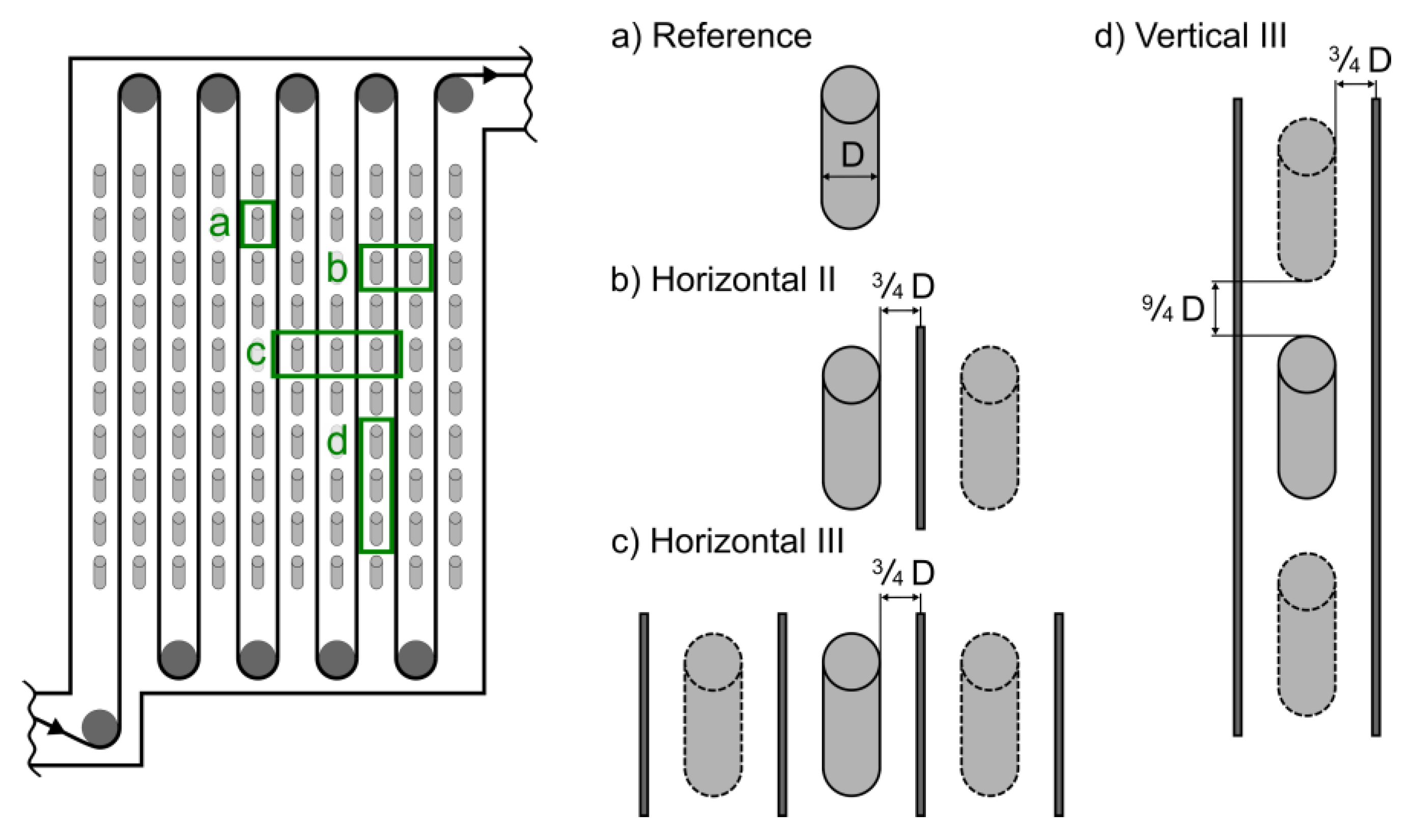
The heating and soaking sections of a CGL furnace offered a broad variety of different radiant tube setups to become the subject of investigation. Three different radiant tube setups were chosen, in addition to the previously described isolated radiant tube, to form the basis of the case studies in the present work, as shown in Figure 5. Setup (a) represented the case of a single tube unaffected by its surroundings. Setup (b) added a radiant tube, horizontally adjacent to the first one. The strip—passing between both tubes—was also taken into account. In order to maximize the number of horizontal neighbors, a second adjacent tube was considered in setup (c). The number of strip-passes also increased in the case of the three-tube horizontal setup, making a total of four passing strips. In addition to the influence of the horizontally adjacent neighbors, the vertical ones also needed to be investigated. Therefore, three vertically-stacked tubes in a column, enclosed by two passing strips, were chosen for setup (d). It could be noted that the relative positions of the tubes and the strip in the setups were based on recommendations by radiant tube manufacturers [38]. These positions were also confirmed with real CGL furnace dimensions.
All tubes in the chosen setups were fully surrounded by other neighboring tubes. The furnace walls of the CGL were neglected due to their unknown influence. This was the main reason to avoid choosing tube setups at the furnace corners or adjoining furnace rolls as part of the present study.
The tubes used in each setup were P-type radiant tubes made of Alloy 602, having a diameter of D = 275 mm and a wall thickness of s = 3 mm. Figure 6 shows the tube geometry relative to a passing strip. The CHT and FEM models had a tube length of 1905 mm since the 250 mm thick insulation was not considered. This was due to the non-availability of the recuperator-part of the burner in the FVM model. A closer look was taken into two different strip widths: a narrow strip with a width of w = 825 mm and a wide strip with w = 1385 mm. The position of the strip relative to the insulation had an offset of 623 mm and 343 mm, respectively. The material chosen for the strip was a standard steel grade based on DIN EN 10025-2 [39]. For the calculation of radiation exchange, the knowledge of the materials’ emissivities became obvious. The emissivity is temperature-dependent and was experimentally determined for Alloy 602 within the used temperature range as ε = 0.95 [40]. The steel strip’s emissivity was assumed to be ε = 0.6 [41].
The built-in self-recuperative burner had a nominal power of 120 kW and could operate in both flame and flameless combustion modes. For the present study, only the flameless mode was considered. The heat input through the recirculating radiant tubes into a CGL furnace was normally controlled by operating the burners in on/off firing mode. This on/off firing led to a change of thermal loads on the radiant tubes and was one of the key aspects of the present investigations. The firing was represented by two temperature distributions, one distribution for the point where the burner was switched on (burner-on point), and a second distribution for the point where the burner was switched off again (burner-off point). The burner firing took place within a cycle time of t = 15 min, representing high-frequency furnace operations like a change in strip’s cross-section or its speed. Each firing cycle was simplified to attain a triangular form, with the ratio of burner-on to burner-off time being 75/25.
During actual CGL operation, the burners were usually fired individually according to the zone temperature controls. In order to simplify these real operating conditions and still be able to quantify the influence of the burner firing, two different firing modes within a setup were considered. The first mode was a synchronous one where all burners switched their firing mode at the same time, i.e., all burners were either on or off simultaneously. In the second mode, used for setup (b), both tubes were fired asynchronously. Two asynchronous firing modes resulted from the permutations with the two furnace chamber temperatures at the burner-on and-off points, marked “async-On” and “async-Off” in Table 2, respectively. Together, both the synchronous and asynchronous modes represented the extremes of possible burner firing modes for two neighboring radiant tubes in a single zone of a CGL furnace.
Each of the setups in the form of CHT models had different boundary conditions, derived from records of actual CGL furnace operation. In addition to the passing strips, a furnace chamber (as an enclosure), representing the rest of the furnace, needed to be considered in order to calculate a setup’s radiation exchange. The enclosure was modeled as a fixed boundary condition, having the same temperature as that of the surrounding furnace zone. The emissivity was set to ε = 1 to eliminate unphysical effects caused by the reflections arising from the enclosure.
For nearly all the setups, the strip was assumed to be isothermal, i.e., it had a constant temperature over all the passes. In order to determine the effect of changing strip temperatures across the width of the CGL furnace, setup (c) (Figure 5) had different strip temperatures over its four strip-passes. The temperatures chosen for the strip and the furnace enclosure are given in Table 3.
The four radiant tube setups, together with the boundary conditions, formed nine different cases, for which the calculation of the central tube’s lifetime indicating parameters was performed, as shown in Table 4.

5. Results and Discussion

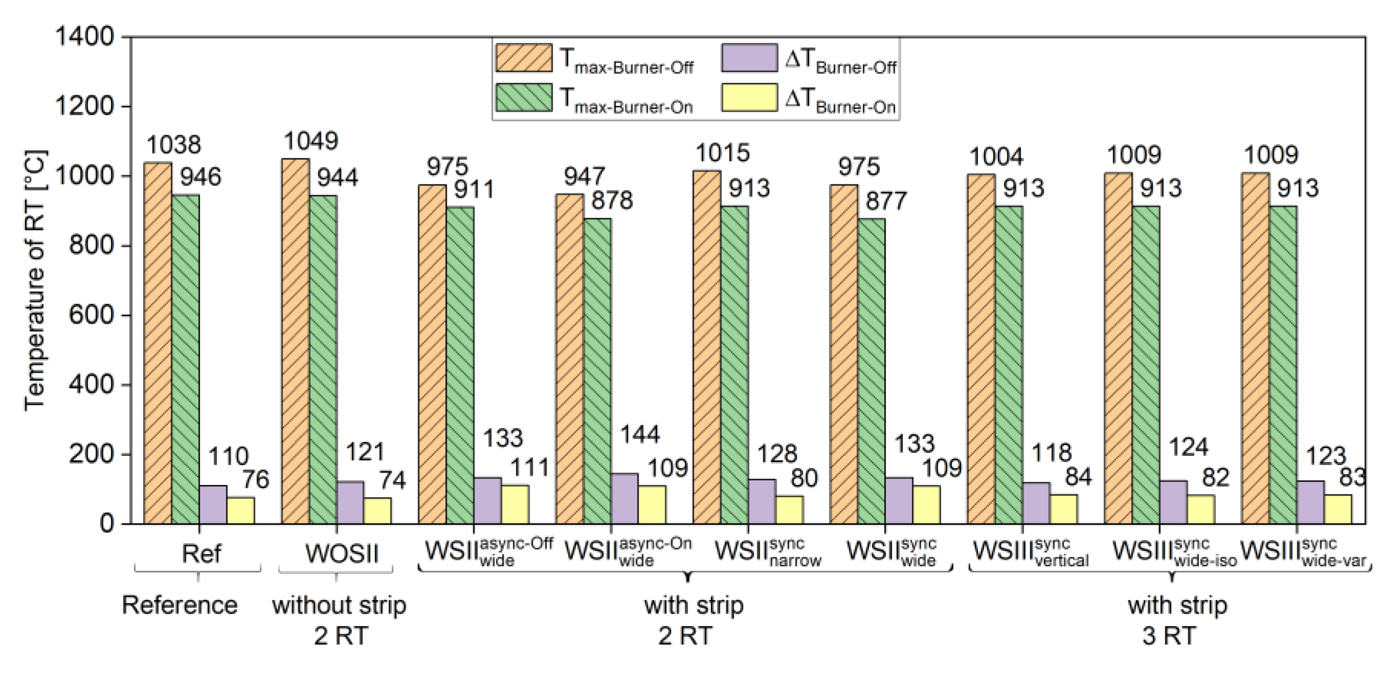
The first step in assessing the effect of the radiation exchange on the parameters indicating the tube’s lifetime involved taking a closer look at the calculated temperature distribution of the individual cases with their boundary conditions. For each case, four characteristic temperature values are shown in Figure 7: the maximum tube temperature (Tmax) and the temperature difference (ΔT) between the maximum and minimum magnitudes for both the burner-on point and -off point distributions.
The introduction of a strip resulted in a decrease in maximum tube temperatures for all its respective cases. Higher temperature gradients were evident in both the tube temperature distributions (at burner-on and -off points) for all cases with a strip (III-IX) compared to the reference case of the isolated tube (I). The temperature gradients for cases with strip were also higher in magnitude than the case without the strip (II), with the exception of the vertical three-tube arrangement case (VII). The case without strip (II) also had a slightly higher maximum tube temperature (11 K) at the burner-off point, accompanied by a higher temperature difference. In contrast, the temperature values showed no significant change at the burner-on point.
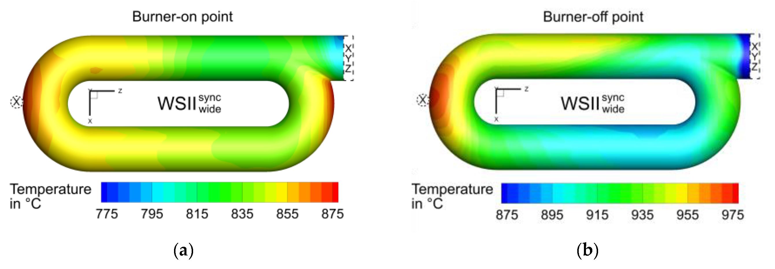
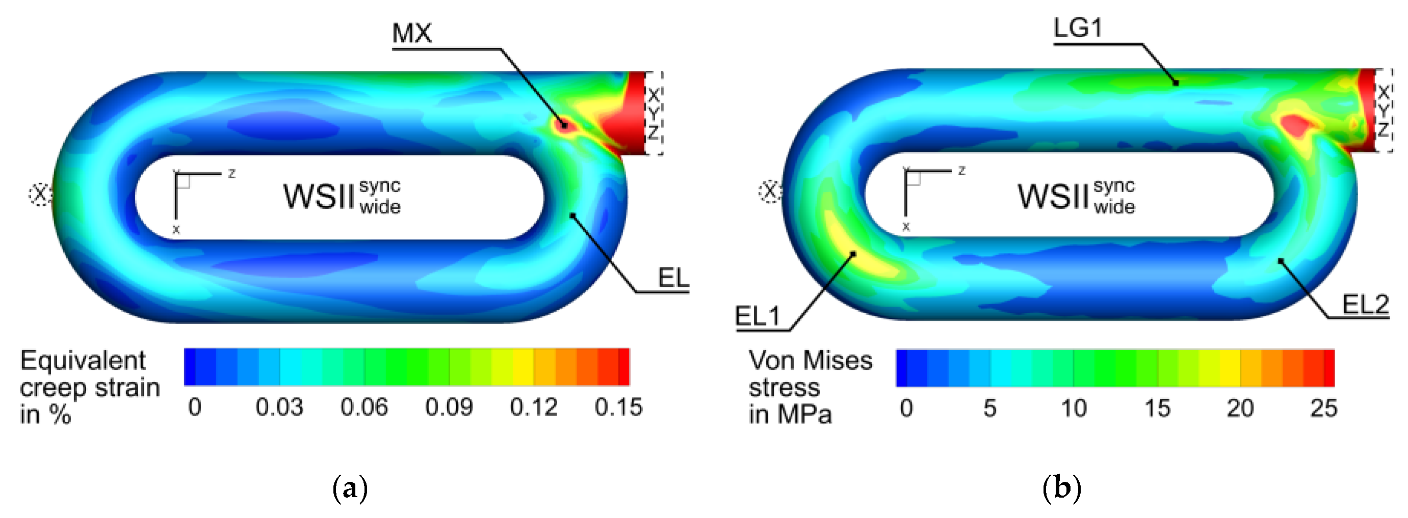
Spatially resolved, the temperature distributions of the reference case (I) showed high temperatures at the first elbow and minimum temperatures at the pinned support (XYZ) [35]. The cases II to IX that were influenced by surroundings showed similar locations of the maximum and minimum temperatures. However, the local distribution of temperatures in the legs and elbows changed accordingly, as shown in Figure 8. Figure 9a shows the creep strain distribution on the tube for case VI at a time of 250 of the total 400 calculated hours. The maximum creep strain occurred at the meeting point of the second elbow to the first leg, followed by the maximums in the first leg, first elbow, and the second elbow, respectively. To evaluate and compare the individual calculations, a point EL (= elbow) was selected on the second elbow. The position of the maximum occurring creep strain MX (= maximum) was not used since the numerical error could not be ruled out due to the proximity to the pinned support (XYZ). It should be noted that the evaluation of both points MX and EL did not show any qualitative deviations.
The corresponding stress distribution in Figure 9b shows the maximum stress location at MX, with the next maximum lying on the first elbow. It could be observed that a direct causal relationship between the creep strains and thermomechanical stresses could not be ascertained. This gave the first indication of the existence of an opposing effect between the stresses and creep strains, caused by the local temperature gradients and the cyclic temperature changes in the radiant tube.
The next step involved the division of results of the calculated creep strains into three parts in order to take a closer look on each of the investigated cases (II-IX): Each of the cases differed in terms of tube arrangement, strip parameters (width, temperature), and burner operating modes.
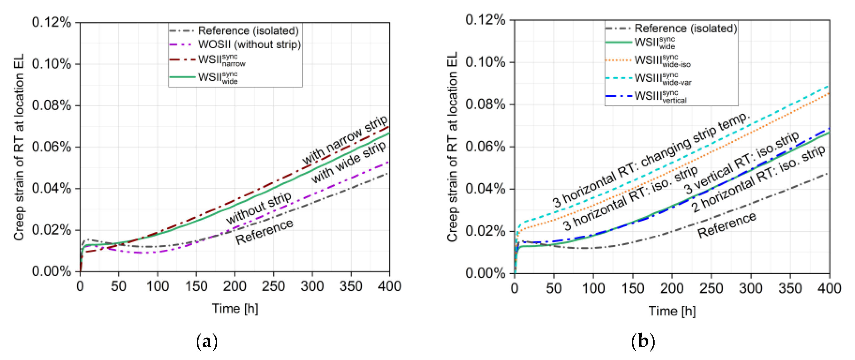
Figure 10a illustrates the effects of the absence and presence of a strip, with two different strip widths (narrow and wide). For comparability, the creep strain of the reference was also shown. Basis of this investigation was setup (b) (Figure 5) with two horizontally adjacent tubes, operating with synchronous fired burners. The results showed a higher creep strain at the end of the 400 h of process time for the cases with a strip—regardless of the strip’s width—compared to the cases without a strip (II) and the reference (I). In contrast, the maximum tube temperatures of the cases with a strip (III-IX) were below that of the reference. A narrower strip tended to cause the highest creep strains compared to the case with a wide strip. It could be noted that no causal correlations could be found between the maximum tube temperatures and the magnitudes of creep strain. For instance, the cases with a strip (III-IX) resulted in higher creep strains than the cases without a strip (II) and the reference (I), even though the latter two had higher maximum tube temperatures.
To summarize, ignoring the strip during the analysis led to an overestimation of the tube’s lifetime. Local temperature gradients and associated temperature changes due to cyclic loading had to be listed as being primarily responsible for the occurring creep strains. A correlation of creep strains solely with the tube temperatures magnitudes was, however, not possible.
The creep strains at location EL for the reference case (I) and certain selected setups with the strip (VI-IX) are shown in Figure 10b. Three different radiant tube arrangements were considered, based on setups (b), (c), and (d) (Figure 5). The effect of two radiating tube partners in vertical direction led to a lower creep strain than two horizontally adjacent radiating partners. This could be ascribed to the fact that the strip’s shielding of some of the neighbors’ radiation strongly influenced the temperatures arising on the tube. In this context, it was also obvious that two neighboring tubes had a greater influence on the central tube than only one neighbor did. By considering horizontally arranged tubes, it became apparent to take a look at the strip’s changing temperature during the passes. Compared to an isothermal strip, a variation in strip temperature led to an increase in the maximum creep strain in the tube.
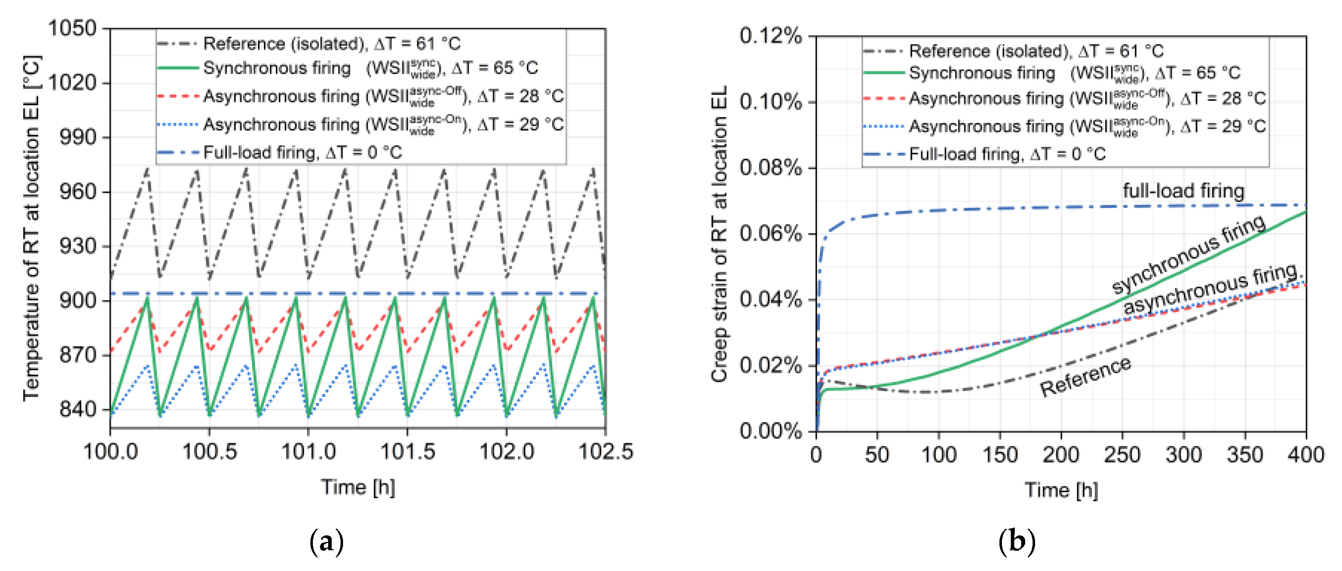
In addition to synchronous firing cases, the two-tube setup was also investigated with asynchronous burner operation (III-IV). Figure 11a shows the temperature-time-cycles at location EL, together with that of the reference. The corresponding creep strains are shown in Figure 11b. Both the asynchronous firing cases showed a lower creep rate than the calculation with synchronous firing. The creep rate was defined as the slope of the creep strain curve in its linear section (150 to 400 h). Also, a slightly lower creep rate could be observed compared to the reference. Two asynchronous firing cases were calculated, one with the furnace chamber temperature of the burner-on point and one at the burner-off point, in order to evaluate their influence. It appeared that the furnace chamber temperature had a marginal effect on the creep rate. A correlation between the creep rates with the local temperature cycles of the tube could be inferred (Figure 11a). With asynchronous firing, the temperature cycle had a value of 28–29 °C at location EL. This magnitude was only half as that seen for the reference (61 °C) or the synchronous firing (65 °C) cases. This supported the observed behavior, linking cyclic changes in thermal loads to rates of creep strain. Higher the local tube temperature cycle values, greater seemed to be the creep rates.
In addition, the effect of full-load firing burner operation was investigated for the tubes in setup (b) (same as for case VI). The resulting creep rate had expectedly the lowest magnitude compared to all other burner firing modes studied in this work. For operating a CGL, this was challenging to adapt since the heating section’s energy input was controlled by burner on/off firing. Further studies must be carried out, including the infrastructure and controls of the furnace.
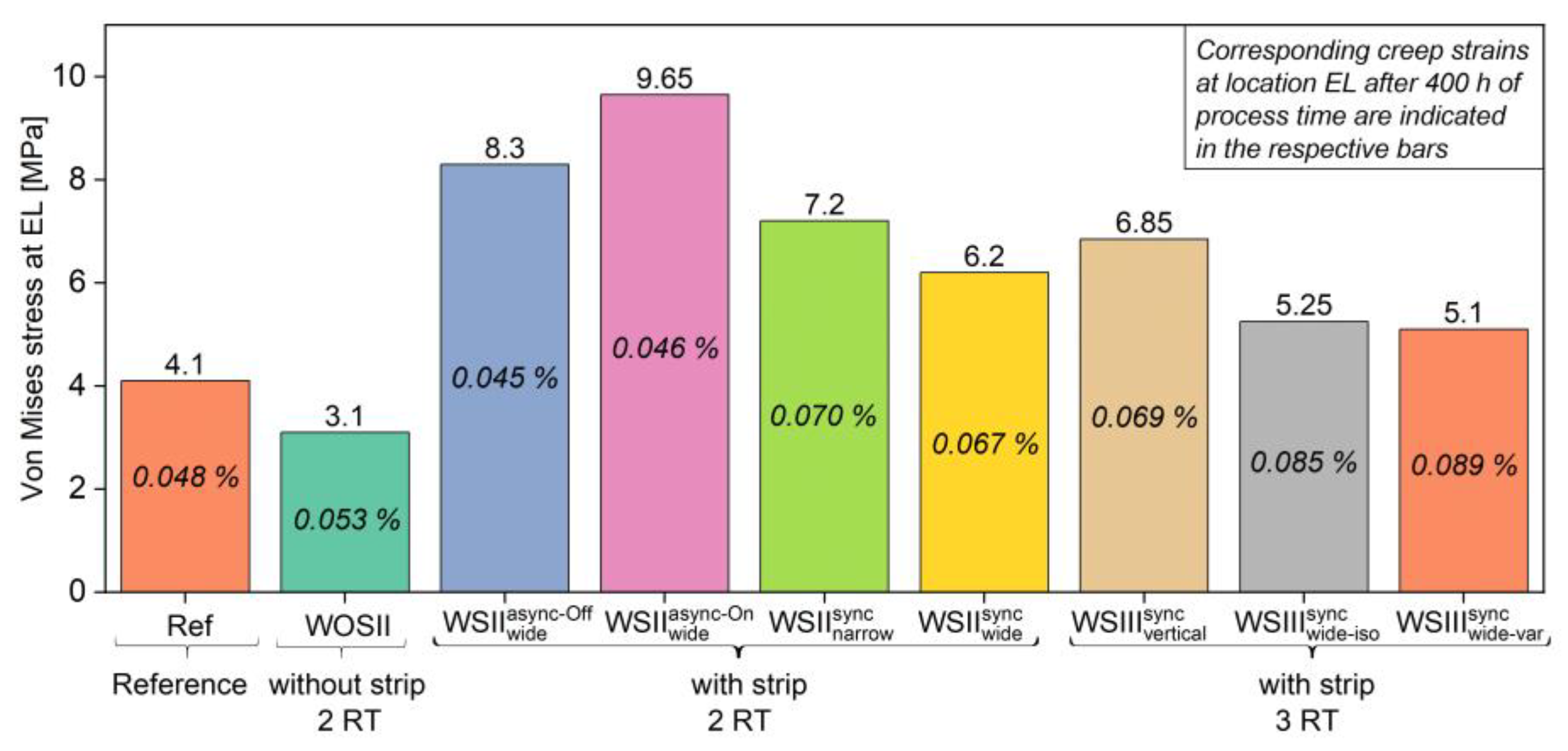
The Von Mises stresses were evaluated at location EL for all cases and are summarized in Figure 12. The opposing effect of creep strain and associated thermomechanical stresses could be observed when comparing the reference (I) with the case without a strip (II). On the one hand, the former case resulted in higher tube stress than the latter one, with the creep strains magnitudes following an opposite pattern. Similar observations could be made for the cases with asynchronous firing modes (III-IV) as well. On the other hand, all cases with the presence of a strip in synchronous burner operation (V-IX), regardless of their arrangement, showed different behavior. Despite higher creep strains in these arrangements, higher stresses occurred compared to the reference.
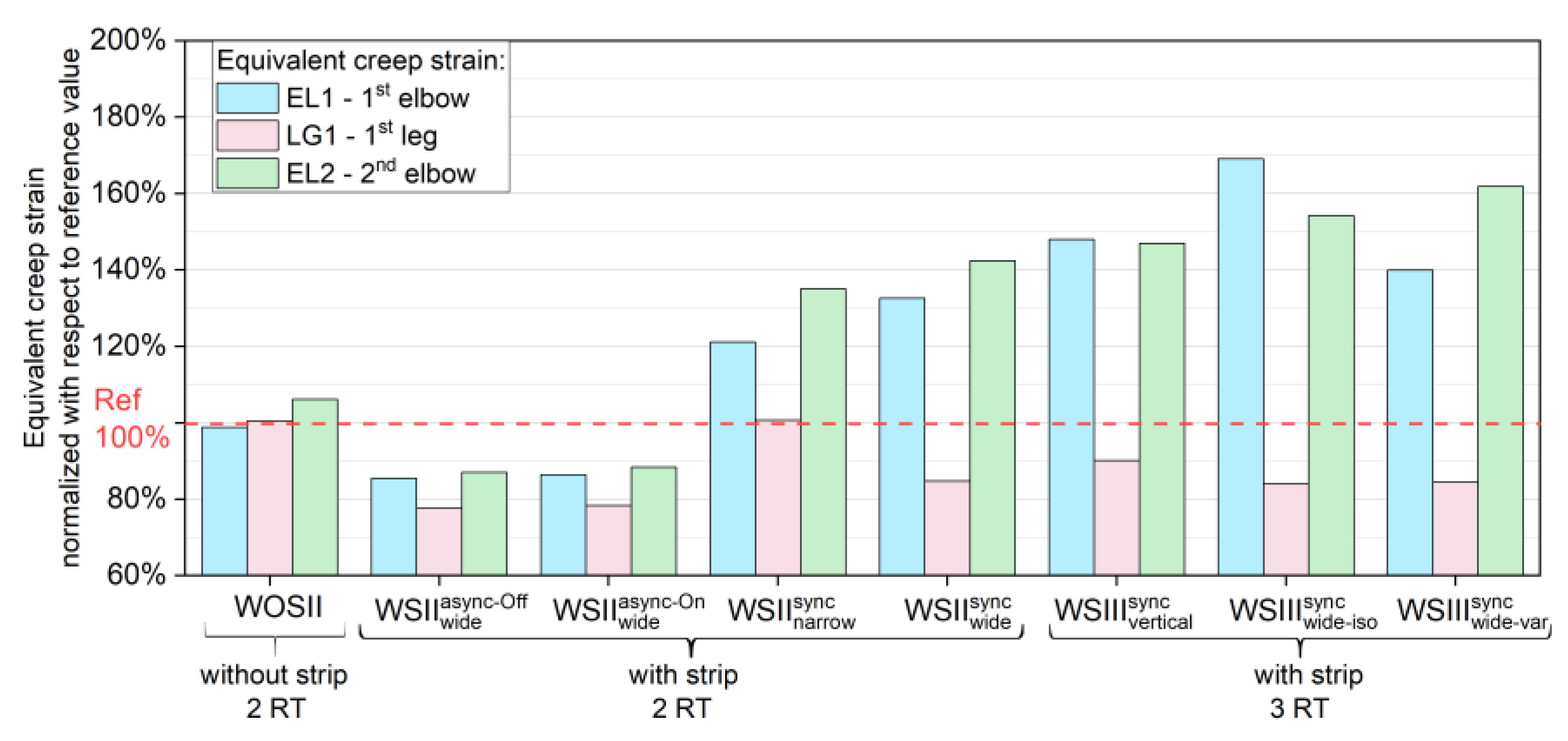
The comparison of creep strains and stresses was carried out not only at the primary evaluation point EL but also at three other secondary evaluation points, as shown in Figure 9b. These points were located on the first leg (LG1), the first elbow (EL1), and, likewise to point EL, on the second elbow (EL2). They represented the next three local maxima. The results of the creep strains and stresses for all nine cases are shown in Figure 13 and Figure 14, respectively. All values were normalized to the reference case (100%).
The creep strains of the cases with asynchronous firing laid below the reference, as already stated at location EL. The results were also consistent for the synchronously firing cases without a strip and with a strip (two horizontal tubes, wide strip, three vertical tubes). Despite these consistencies, deviations could be seen while taking a look at the case with the narrow strip (V). Its resulting creep strain showed similar behavior as the wide strip case (VI), but, in contrast to previous observations, the stresses were lower than that of the reference. A similar behavior could be seen for the three horizontally adjacent tubes (VIII-IX), regardless of the local strip’s temperatures. Taking a closer look at the evaluation point on the first leg, it could be observed that all cases showed creep strains lower than or of equal magnitude to the reference.
The partly contrary results showed that a simple correlation of stresses and creep strains with the given boundary conditions was not possible. It should be noted that all stresses were still below the yield strength of Alloy 602 at the respective temperatures.

6. Conclusions

The focus of the present work was the evaluation of the effect of surrounding radiation on radiant tube lifetime in vertical strip annealing furnaces. For this purpose, the creep strains and associated thermomechanical stresses were calculated as service life-indicating parameters for various radiant tube setups. The setups consisted of two or three adjacent tubes, arranged in a horizontal row or a vertical column. The model boundary conditions were changed in order to identify their individual influences, which included changes in the burner firing mode, the strip’s width, and its temperature. A reference case with a single radiant tube treated separately from the rest of the furnace was chosen to compare and classify the results. An in-house developed and validated numerical method was used to calculate the temperature distributions for every case. Subsequently, a creep analysis on the tubes was carried out to determine the lifetime indicating parameters.
The following conclusions could be drawn from the assessment of the effect of surrounding radiation on radiant tube lifetime:
  • Peak tube temperatures decreased, and the maximum tube temperature gradients at the burner-on and -off points invariably increased upon the introduction of adjacent tubes and a strip as radiating partners, compared to an isolated radiant tube.
  • Under synchronous burner firing, the presence of a passing strip—irrespective of its width—coupled with adjacent radiant tubes, resulted in an increase in the maximum tube deformation due to creep.
  • The choice of the asynchronous firing of burners in a furnace zone was preferable to synchronous firing with regard to the tube’s creep deformation.
  • The full-load firing case expectedly showed the least creep rate. It might, however, be difficult to employ in practice for radiant tubes in a CGL furnace.
  • The higher the local tube temperature difference between the burner-on and -off points in a firing cycle, the greater was the creep rate at the respective tube region. This could be clearly seen while comparing the isolated tube, synchronous, and asynchronous firing cases.
  • The highest creep deformation was observed for the setup with three radiant tubes arranged horizontally compared to the vertical arrangement, even though the maximum and minimum tube temperatures and its gradients in a firing cycle were similar. Adjacent radiant tubes strongly affected each other as soon as a strip shielded a part of their radiation exchange area.
  • Changes in strip temperature had a marginal effect on the tube’s creep deformation. Evaluating the radiant tube lifetime dependent on the tubes’ positions in a CGL furnace, either near the strip entry or towards the strip exit seemed to be more complex than that. The strip cross-section was clearly a parameter of higher significance than locally changing strip temperatures.
  • The role played by the opposing effect, existing between creep deformation of the tube and its thermomechanical stresses, was evident. Therefore, a pattern elucidating a simple correlation between the two was difficult to observe, except, e.g., the asynchronous firing cases.
  • The investigations indicated that cyclic temperature changes—occurring either due to burner on/off firing or process changes—and the corresponding local temperature gradients were mainly responsible for the tube’s creep deformation.
In future investigations, attention would be shifted towards double-P-type radiant tubes due to their wide use in radiant tube heating and soaking sections of the CGL furnaces. In addition, an enlargement of the radiating surroundings is planned to include up to a matrix of nine radiant tubes. This would include not only an extension of the presented numerical models but also a detailed validation by means of temperature measurements on a currently running CGL furnace. An extension of the simulated process times up to several thousand hours is necessary in order to meet the real conditions and, therefore, lead to better assessments of radiant tube lifetime.

Author Contributions

Conceptualization, D.B., N.K.K., N.S., and H.P.; methodology, D.B., N.K.K., and N.S.; software, D.B. and N.K.K.; validation, N.K.K. and N.S.; investigation, D.B. and N.K.K.; data curation, D.B. and N.K.K.; writing—original draft preparation, D.B. and N.K.K.; writing—review and editing, D.B., N.K.K., and N.S.; visualization, D.B. and N.K.K.; supervision, N.S. and H.P. All authors have read and agreed to the published version of the manuscript.

Funding

This research received no external funding.

Acknowledgments

We are immensely grateful to Romana Schwing and Stefan Linn of the Chair and Institute for Materials Technology (MPA-IfW) at Technische Universität Darmstadt for providing the creep models of high-temperature Ni-based alloys. Their invaluable contribution towards explaining the creep behavior of those alloys under alternating temperatures is also greatly appreciated.

Conflicts of Interest

The authors declare no conflict of interest.

References

  1. Wünning, J.G.; Beck, E.; Schönenberg, R.; Zeizinger, S. Operating Experience with Regard to New Double P Radiant Tube Technology in a Vertical Galvanizing Line. In Proceedings of the 98th Annual Meeting of the Galvanizers Association, Columbus, OH, USA, 22–25 October 2006. [Google Scholar]
  2. Quinn, D.E. Regenerative Radiant Tube Combustion Systems for Continuous Strip Annealing Furnaces. In Proceedings of the 91st Annual Meeting of the Galvanizers Association, Jackson, MS, USA, 24–27 October 1999. [Google Scholar]
  3. Morgan, G.; James, M.; Thomas, A. Improvement programme for optimising furnace Radiant Tubes (Tata-Corus). In Proceedings of the 100th Annual Meeting of the Galvanizers Association, Baltimore, MD, USA, 26–29 October 2008. [Google Scholar]
  4. Steck-Winter, H.; Unger, G. Thermal processing plants in the smart factory. Heat Process. 2017, 3, 95–102. [Google Scholar]
  5. Speets, R.; Wu, H.; Pronk, P. Improving the performance of continuous annealing lines by model predictive control. In Proceedings of the Industrial Furnaces and Boilers—INFUB 10, Porto, Portugal, 7–10 April 2015. [Google Scholar]
  6. Niederer, M.; Steinböck, A.; Strommer, S.; Kugi, A. Control of radiant tubes in an indirect-fired strip annealing furnace for improved efficiency. In Proceedings of the European Control Conference ECC, Zürich, Switzerland, 17–19 July 2013; pp. 4106–4111. [Google Scholar]
  7. Pfeifer, H.; Nacke, B.; Beneke, F. Handbook of Thermoprocessing Technologies Volume 2: Plants, Components, Safety; Vulkan-Verlag: Essen, Germany, 2015. [Google Scholar]
  8. Chakrabarti, S.; Sarkar, S.; Kumar, S.; Singh, G.R.P.; Maheshwari, M.D. Failure of radiant tubes in a continuous galvanising furnace. Tata Search 2003, 399–403. [Google Scholar]
  9. Yoon, K.; Jeong, D. Oxidation failure of radiant heater tubes. Eng. Fail. Anal. 1999, 6, 101–112. [Google Scholar] [CrossRef]
  10. Pohland vom Schloß, H.; Lucka, K.; Köhne, H. Hochtemperaturkorrosion an metallischen Strahlheizrohren in Abgasatmosphäre. Gaswaerme Int. 2007, 56, 499–502. [Google Scholar]
  11. Tari, V.; Najafizadeh, A.; Aghaei, M.; Mazloumi, M. Failure analysis of ethylene cracking tube. J. Fail. Anal. Prev. 2009, 9, 316–322. [Google Scholar] [CrossRef]
  12. Ul-Hamid, A.; Tawancy, H.M.; Mohammed, A.-R.I.; Abbas, N.M. Failure analysis of furnace radiant tubes exposed to excessive temperature. Eng. Fail. Anal. 2006, 13, 1005–1021. [Google Scholar] [CrossRef]
  13. Illgner, K.H.; Sundermann, J. Untersuchung eines Falles von Hochtemperaturkorrosion an einem M-Strahlrohr. Gaswaerme Int. 2007, 56, 297–299. [Google Scholar]
  14. Saravanan, P.; Sahoo, G.; Srikanth, S.; Ravi, K. Failure analysis of radiant tube burners in continuous annealing line (CAL) of an integrated steel plant. J. Fail. Anal. Prev. 2011, 11, 286–292. [Google Scholar] [CrossRef]
  15. Zhu, Z.; Cheng, C.; Zhao, J.; Wang, L. High temperature corrosion and microstructure deterioration of KHR35H radiant tubes in continuous annealing furnace. Eng. Fail. Anal. 2012, 21, 59–66. [Google Scholar] [CrossRef]
  16. Palaniyandi, V.; Allsup, R.; Moser, R. Failure Analysis of HP-40 (mod Nb) Furnace Radiant Tube. In Proceedings of the Materials Science & Technology—Conference & Exhibition, Pittsburgh, PA, USA, 5–9 October 2008. [Google Scholar]
  17. Tsioumanis, N.; Brammer, J.G.; Hubert, J. Flow processes in a radiant tube burner: Combusting flow. Energy Convers. Manag. 2011, 52, 2667–2675. [Google Scholar] [CrossRef]
  18. Ahanj, M.D.; Rahimi, M.; Alsairafi, A.A. CFD modeling of a radiant tube heater. Int. Commun. Heat Mass Transfer 2012, 39, 432–438. [Google Scholar] [CrossRef]
  19. Wang, Y.; Li, J.; Zhang, L.; Ling, H.; Li, Y. Numerical simulation of the thermal process in a W-Shape radiant tube burner. JOM 2014, 66, 1253–1264. [Google Scholar] [CrossRef]
  20. Xu, Q.; Feng, J. Analysis of nozzle gas speed on the performance of the zoned and staged gas-fired radiant tube. Appl. Therm. Eng. 2017, 118, 734–741. [Google Scholar] [CrossRef]
  21. Xu, Q.; Feng, J.; Zhou, J.; Ding, C.; Bai, Z.; Zang, Y. Performance analysis of a novel W-type radiant tube. Appl. Therm. Eng. 2019, 152, 482–489. [Google Scholar] [CrossRef]
  22. Xu, Q.; Feng, J.; Zhou, J.; Liu, L.; Zang, Y.; Fan, H. Study of a new type of radiant tube based on the traditional M-type structure. Appl. Therm. Eng. 2019, 150, 849–857. [Google Scholar] [CrossRef]
  23. Irfan, M.A.; Chapman, W. Thermal stresses in radiant tubes due to axial, circumferential and radial temperature distributions. Appl. Therm. Eng. 2009, 29, 1913–1920. [Google Scholar] [CrossRef]
  24. Irfan, M.; Chapman, W. Thermal stresses in radiant tubes: A comparison between recuperative and regenerative systems. Appl. Therm. Eng. 2010, 30, 196–200. [Google Scholar] [CrossRef]
  25. Dini, G.; Vaghefi, S.M.M.; Lotfiani, M.; Jafari, M.; Safaei-Rad, M.; Navabi, M.; Abbasi, S. Computational and experimental failure analysis of continuous-annealing furnace radiant tubes exposed to excessive temperature. Eng. Fail. Anal. 2008, 15, 445–457. [Google Scholar] [CrossRef]
  26. Hellenkamp, M.; Pfeifer, H. Thermally induced stresses on radiant heating tubes including the effect of fluid–structure interaction. Appl. Therm. Eng. 2016, 94, 364–374. [Google Scholar] [CrossRef]
  27. Schmitz, N.; Hellenkamp, M.; Pfeifer, H.; Cresci, E.; Wünning, J.; Schönfelder, M. Radiant tube life improvement for vertical galvanizing lines. In Proceedings of the 10th International Conference on Zinc and Zinc Alloy Coated Steel, AIST Galvatech, Toronto, ON, Canada, 31 May–4 June 2015; pp. 473–480. [Google Scholar]
  28. Schmitz, N.; Schwotzer, C.; Pfeifer, H. Increasing lifetime of metallic recirculating radiant tubes. Heat Process. 2018, 1, 49–55. [Google Scholar]
  29. Caillat, S.; Pasquinet, C. Radiant tubes lifetime prediction in steel processing lines using fluid–structure interaction modelling. Energy Procedia 2017, 120, 596–603. [Google Scholar] [CrossRef]
  30. Karthik, N.K.; Schmitz, N.; Pfeifer, H.; Schwing, R.; Linn, S.; Kontermann, C.; Oechsner, M. Einfluss von Temperaturwechselbeanspruchung auf das Verformungsverhalten von Ofenkomponenten und deren Lebensdauer. Berg Huettenmaenn. Monatsh. 2019, 164, 364–371. [Google Scholar] [CrossRef] [Green Version]
  31. Karthik, N.K.; Schmitz, N.; Pfeifer, H. Effect of cyclic thermal loading on the lifetime of furnace components. In Proceedings of the ECHT—European Conference on Heat Treatment, Bardolino, Italy, 5–7 June 2019. [Google Scholar]
  32. Karthik, N.K.; Schmitz, N.; Pfeifer, H. Lebensdauer metallischer Ofenkomponenten bei Temperaturwechselbeanspruchung (Teil 1). Prozesswärme 2019, 2, 59–66. [Google Scholar]
  33. Schwing, R.; Linn, S.; Kontermann, C.; Oechsner, M. Zum Einfluss von Temperaturwechselbeanspruchungen auf das Kriechverhalten von hochwarmfesten metallischen Werkstoffen. In Proceedings of the 41. FVWHT-Vortragsveranstaltung, Düsseldorf, Germany, 30 November 2018. [Google Scholar]
  34. Schwing, R.; Linn, S.; Kontermann, C.; Oechsner, M. Lebensdauer metallischer Ofenkomponenten bei Temperaturwechselbeanspruchung (Teil 3). Prozesswärme 2019, 2, 59–65. [Google Scholar]
  35. Büschgens, D.; Karthik, N.K.; Schubert, C.; Schmitz, N.; Pfeifer, H. Investigation of the Influence of Proximal Radiation on the Thermal Stresses and Lifetime of Metallic Radiant Tubes in Radiation-Dominated Industrial Furnaces. HTM J. Heat Treatm. Mat. 2019, 74, 392–405. [Google Scholar] [CrossRef]
  36. Büschgens, D.; Lenz, W.; Pfeifer, H.; Strämke, M. Development of an Interactive Batch Planning System for Plasma Nitriding Furnaces. HTM J. Heat Treatm. Mat. 2019, 74, 136–147. [Google Scholar] [CrossRef]
  37. Hottel, H.C.; Sarofim, A.F. Radiative Transfer; McGraw Hill: New York, NY, USA, 1967; pp. 83–93. [Google Scholar]
  38. WS Wärmprozesstechnik GmbH: Prerequisities for the Installation of Radiant Tubes (in German). Version 132. 2001. Available online: https://flox.com/documents/de_Strahlrohreinbau.pdf (accessed on 19 December 2019).
  39. DIN EN 10025-2, Hot Rolled Products of Structural Steels—Part 2: Technical Delivery Conditions for Non-Alloy Structural Steels; German Version EN 10025-2:2019; BSI: London, UK, 2019.
  40. Karthik, N.K.; Schwing, R.; Linn, S.; Bittner, P.; Ackermann, H.; Diarra, D.; Oechsner, M.; Pfeifer, H. Einfluss thermischer Lastwechsel auf die Lebensdauer hochbelasteter Ofenkomponenten aus metallischen Hochtemperatur-Werkstoffen. In Schlussbericht IGF-Forschungsvorhaben 19068 N; Forschungsgemeinschaft Industrieofenbau (FOGI): Frankfurt am Main, Germany, 2019. [Google Scholar]
  41. Funkte, T.; Kirchhoff, R.; Oertel, H.; Rink, M. Messung der Emissionsgrade von Stählen und Ofenbaumaterialien in verschiedenen Atmosphären als prozeßbezogene Stoffdaten für Wärmebehandlungsanlagen. In Forschungsgemeinschaft Industrieofenbau Forschungsbericht 47-652; Forschungsgemeinschaft Industrieofenbau (FOGI): Frankfurt am Main, Germany, 1998. [Google Scholar]
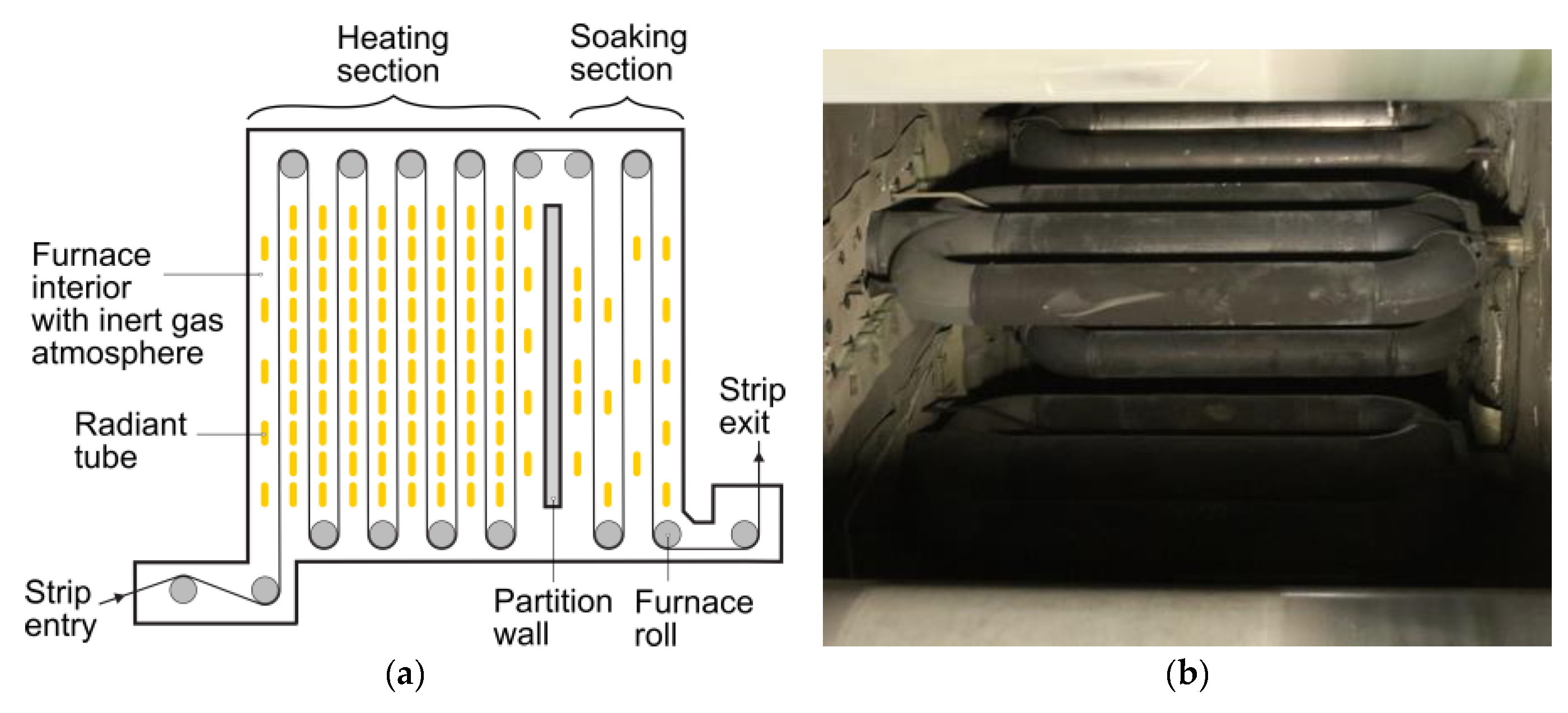
Figure 1. (a) Schematic of the annealing furnace of a continuous strip galvanizing line (CGL); (b) View from the bottom into the heating section of an annealing furnace.
Applsci 10 01748 g001
Figure 2. Examples of damaged recirculating and non-recirculating metallic radiant tubes in CGLs.
Applsci 10 01748 g002
Figure 3. Example of temperature changes in a double P-type radiant tube in a CGL furnace: Region 1 representing the classic case of tube temperatures under burner on/off firing, Region 2 showing an instance of burner full load firing, and Region 3 illustrating tube temperature changes due to strip parameter variation.
Applsci 10 01748 g003
Figure 4. Working principle of the coupled heat transfer (CHT) model as part of a fluid-structure-interaction (FSI) approach.
Applsci 10 01748 g004
Figure 5. Heating section of a CGL and the chosen radiant tube setups.
Applsci 10 01748 g005
Figure 6. P-type radiant tube used for this investigation.
Applsci 10 01748 g006
Figure 7. Comparison of the temperature distributions of all nine cases with the help of characteristic values.
Applsci 10 01748 g007
Figure 8. Temperature distributions at the burner-on (a) and-off (b) points for case VI.
Applsci 10 01748 g008
Figure 9. Results for case VI showing: (a) creep strain; (b) stress distribution (burner-on point).
Applsci 10 01748 g009
Figure 10. Creep strain magnitudes at location EL (= evaluation point on second elbow) for cases used to investigate the strip influence: (a) presence or absence of a strip; (b) different arrangements of two or three adjacent tubes.
Applsci 10 01748 g010
Figure 11. Results of burner firing operations: (a) temperature-time-cycle and (b) creep strain at location EL.
Applsci 10 01748 g011
Figure 12. Von Mises stresses and corresponding creep strains at location EL after 400 h of process time for all nine cases.
Applsci 10 01748 g012
Figure 13. Creep strain at locations EL1 (= first elbow), LG1 (= first leg), and EL2 (= second elbow) after 400 h of process time for all nine cases.
Applsci 10 01748 g013
Figure 14. Von Mises stresses at locations EL1, LG1, and EL2 after 400 h of process time for all nine cases.
Applsci 10 01748 g014
Table 1. Outline of chosen discretizations for the finite volume method (FVM), coupled heat transfer (CHT), and finite element method (FEM) models.
ModelMesh TypeType of ElementsNumber of ElementsSolution Domain
FVM3-D volumetric100 % tetrahedral990 000
-
Self-recuperative burner
-
Radiant tube mounted in test bench
-
Furnace chamber of test bench
-
Heat sinks available in test bench
CHT3-D surface100 % triangular12 355
-
Chosen radiant tube setup
-
Strip passing between the tubes
-
Furnace chamber as an enclosure (walls, rolls and other RTs neglected
FEM3-D surface99.44 % quadratic
0.56 % triangular
6 269
-
Central radiant tube
Table 2. Outline of the FVM, CHT, and FEM models.
ModelSoftwareSolving Approach(Sub)Models
FVMANSYS Fluent®Semi-Implicit Method for Pressure-Linked Equations
-
Turbulence: Realizable k-ε
-
Combustion: Eddy Dissipation Concept
-
Radiation: Discrete Ordinates with Weighted-Sum-of-Gray-Gases
CHTMATLAB®Hottel’s zonal method
-
Radiation: Surface-to-Surface (full resolution)
Abaqus®Pure heat transfer analysis
-
Conduction: Shell heat conduction
FEMAbaqus®Coupled-Temperature-DisplacementMaterial model consisting of:
-
Time-independent thermoelasto-plastic strain components
-
Time-dependent plastic strain included in the extended Graham-Walles creep model
Table 3. Temperature boundary conditions for strip and furnace chamber used for all setups.
Burner-on PointBurner-off Point
Strip- isothermal
- variable
820 °C
800–10–820–830 °C
850 °C
830–840–850–860 °C
Furnace chamber- with strip
- without strip
860 °C
895 °C
900 °C
940 °C
Table 4. Nine investigated cases and their radiant tube setups and boundary conditions.
CaseNameSetupNo. of TubesArrangementStripBurner Firing
IRefa1---
IIWOSIIb2horizontal-sync
IIIWSIIasync-Off
wide
b2horizontalwideasync-Off
IVWSIIasync-On
wide
b2horizontalwideasync-On
VWSIIsync
narrow
b2horizontalnarrowsync
VIWSIIsync
wide
b2horizontalwidesync
VIIWSIIIsync
vertical
d3verticalwidesync
VIIIWSIIIsync
wide-iso
c3horizontalwide, isothermalsync
IXWSIIIsync
wide-var
c3horizontalwide, variablesync