Review

Mechanical Strength Evaluation of Elastic Materials by Multiphysical Nondestructive Methods: A Review

1
School of Mechano-Electronic Engineering, Xidian University, Xi’an 710071, China
2
Center for Advanced Diffusion-Wave and Photoacoustic Technologies (CADIPT), Department of Mechanical and Industrial Engineering, University of Toronto, Toronto, ON M5S 3G8, Canada
*
Authors to whom correspondence should be addressed.
Appl. Sci. 2020, 10(5), 1588; https://doi.org/10.3390/app10051588
Submission received: 24 December 2019 / Revised: 17 February 2020 / Accepted: 19 February 2020 / Published: 27 February 2020
(This article belongs to the Special Issue Nondestructive Testing (NDT))

Abstract

:
The main purpose of industrial nondestructive testing (NDT) is to diagnose the stability, reliability and failure probability of materials, components and structures. Industrial component mechanical strength is one of the most important properties NDT is used to characterize. Subtle but perceptible changes in stress-strain behavior can be reliable indicators of defect formation. A detailed review on the state-of-the-art NDT methods using optical-radiation, photoacoustic, and photothermal techniques for mechanical strength evaluation and defect pre-diagnosis is presented in this article. Mechanical strength is analyzed in terms of the deformation/strain field, the stress-strain relation, and the residual stress in an elastic material subjected to tensile or compressive loading, or impact. By introducing typical NDT experiments, the history and features of each methodology are revisited and typical applications are discussed. This review also aims to be used as a reference toward further research and development of NDT technologies characterizing mechanical strength of materials and components.

1. Introduction

Nondestructive testing/evaluation (NDT/NDE) is a collection of scientific techniques which are able to evaluate the properties and condition of materials without inflicting permanent damage on them. They were originally designated for inspecting parts, products, and structures of high value. The number of published research reports on NDT rapidly increased in the beginning of the 20th century because of industrialization and the two World Wars. There have been wide applications for NDT technologies in numerous fields such as industrial manufacturing [1,2], aerospace and aeronautics [3], civil engineering [4,5], and material science and technology [6,7]. Practical NDT techniques used for materials characterization can reduce maintenance costs and enforce lifetime management [8]. From the viewpoint of NDT on components made from solid elastic materials such as alloys, polymers and composites, quality is assessed by inspecting the possible existence of defects and changes in mechanical strength [9,10]. Conventionally, the mechanical strength of a material is measured with a tensile machine and the stress-strain relation is determined by dynamic tensile testing from load-free to failure [11,12,13]. The stress-strain data are recorded on samples of cylindrical, center-necked shape and contact stress/strain measurement modules such as adhesive transducers are usually part of the machine. Such tensile tests are destructive because samples undergo irreversible deformation during the tensile test. To resolve the problem associated with mechanical strength testing, several nondestructive methodologies have been developed for the purpose of stress-strain evaluation. Some of them focus on noncontact approaches which characterize the change of stress-strain state by other physical fields during tensile testing. Other methodologies do not involve tensile testing but are devoted to measuring surface or internal residual stress distribution in an elastic sample both qualitatively and quantitatively. Nevertheless, the ultimate goal always is pre-diagnosing the mechanical strength of a component before actual cracks and failure occur.
This review article discusses typical NDT methodologies that measure stress or strain by means of both contact and noncontact configurations. Noncontact methods can be used under extreme testing conditions or for in-situ inspection. Features of these noncontact NDT modalities are discussed with regard to their physical basis and state-of-the-art applications. No ranking of the various techniques is made or conclusions drawn with respect to their relative advantages because they all have distinctive features and limitations. It is expected that this review article will help interested readers to learn about the underlying physical principles, development histories and modern applications of a number of major NDT methods used for industrial quality control to-date.

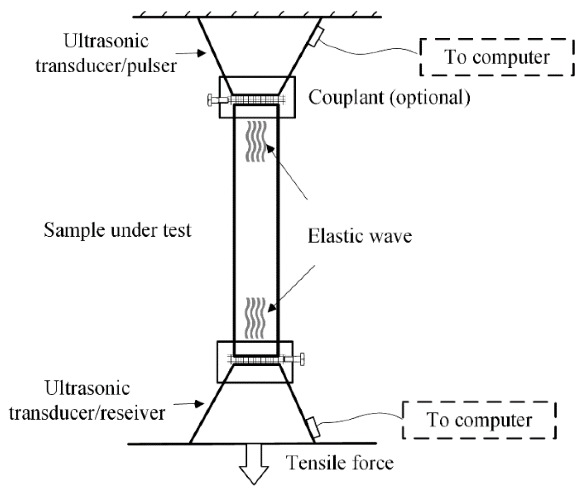
2. Noncontact Mechanical Property Testing Methods

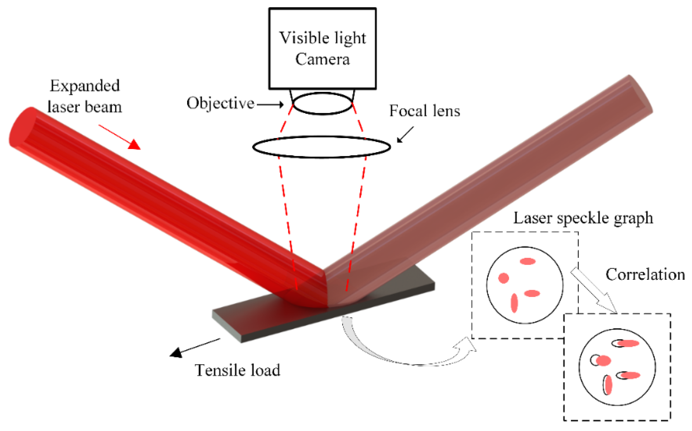
2.1. Optical/Radiation Techniques

The stress-strain relation of elastic materials is important because it is not only a way to characterize the hardness and brittleness of raw materials, but also reveals the mechanical status of a sample under test [14,15]. Normally, the strain value is measured with a strain gauge affixed on the sample surface. Under extreme conditions such as high temperature, strain sensors along with special designs of insulating and high-Curie-temperature materials, are used for stress-strain measurements in contact configurations [16,17,18,19]. Such a scheme cannot satisfy the requirements of many in-field applications due to difficulties with transducer bonding. To perform totally noncontact measurements, digital-image correlation (DIC), a.k.a. digital laser speckle (DLS), a purely optical imaging technique, was devised. This method was first proposed by Lyons et al. [20] with the basic principle shown in Figure 1. To avoid blackbody radiation from a high temperature surface, a visible-range expanded-beam laser is usually adopted in DIC measurement to generate diffuse-reflection-induced speckle patterns. A camera (with optical filter) is placed in front of the sample to record speckle images during tensile tests. By cross-correlating the digital images before and after tensile loading, the displacement field can be determined using the following equation [21]:
( u x u y ) = 1 V i ( Δ m P x Δ n P y )
where ux and uy represent the two orthogonal displacement fields in the camera, Vi is the image size and Δm, Δn are the respective cross-correlation values. P stands for the pixel pitch which is determined by the resolution of camera. The ultimate strain field of interest can be further derived from the gradients of ux and uy. Using the proposed method, Anwander et al. achieved strain measurements in tensile tests at 1200 Celsius degree with aluminum [21]. Four years later, Vǒlkl et al. further increased the temperature to 3000 degree with an Ohmic heater and conducted strain field measurements using a similar DIC schematic [22]. Zhu et al. developed a time-dependent DIC system and dynamically recorded the change of strain field under a constant loading rate with respect to non-metallic composites [23]. By using laser extensometry, the local strain rate value can be characterized by time-dependent phase shift of correlated signal thus real-time measurement is possible.
Another interesting topic is exploring the stress-strain behavior of alloys under high temperature which can reveal the strength of materials under extreme conditions, and also investigating how they react to thermal stress at such high temperatures. Such a thermal reactive character can be used to determine thermal compatibility with other materials in a heterogeneous structure [24]. Pan et al. introduced an optical bandpass imaging system shown in Figure 2 to evaluate surface thermal strain without a surface irradiating laser source [25]. The bandpass filter allows only the violet-to-blue light to pass and avoids interferences from blackbody radiation at high temperatures. The use of an incoherent light source makes the system less costly but still sensitive [26]. The DIC of incoherent speckle imaging technique can also be used for real-time strain recording, as proposed by Yang et al., to assist optimization of supersonic aircraft coating-material thermal shock processes [27].
Apart from industrial applications, noncontact optical measurements can also be used to perform strength evaluation of concrete in civil engineering using an alternative configuration of DLS. A narrow collimated visible laser beam impinges perpendicularly on a sample surface, while the camera monitors and captures scattered laser light from the incident spot at a non-normal angle in a scanning patterns over the surface so as to determine roughness mappings. This method is usually named laser triangulation. A series of tests with laser triangulation scanning were carried out [28,29,30] to systematically quantify mechanical bonding strength between different concrete layers. The correlation between adhesive performance of concrete and roughness, grain size, texture etc. was investigated. Optical non-contact measurements represent an accurate and effective modality for evaluating mechanical strength of inelastic building materials.
DIC is a successful approach to remotely detect small displacements and reconstruct strain fields. It relies heavily on the resolution, processing speed and aberration performance of the camera. However, there are some limitations with respect to its applications. The processing algorithm requires input of speckle images, therefore, the signal-to-noise ratio from highly reflective surfaces can easily deteriorate. Furthermore, the strain field inside the sample cannot be visualized with purely optical means. The existence of local stress/strain should be justified with other techniques to yield a comprehensive stress-strain evaluation. Ionizing radiative electromagnetic waves have deep penetration and thus can be used for internal stress-strain evaluation.
Among the established methods, X-ray diffraction is regarded as a classic and powerful tool for diagnosing subsurface or internal stress without contact. Having very small wavelength, X-ray radiation penetrates metallic materials and diffracts from irregular-lattice area caused by internal stress/strain, a common case in the production of composites consisting of non-metal and metal layers with different thermal expansion/contraction properties [31,32].
X-rays have also been shown to be capable of evaluating the stress-strain relation from mechanical tests by single-angle, two-angle and sin2 Ψ scattering modes [33,34,35]. The schematic of X-ray diffraction and the associated relevant coordinates is shown in Figure 3. The basic principle for evaluating strain due to external load can be represented as a function of latitudinal lattice spacing dΨΦ as [32,33]:
ε ψ ϕ = d ψ ϕ d 0 d 0
where, d0 is the lattice spacing before deformation. The strain component can be determined by analyzing the X-ray radiation signal in different directions, i.e., at angles Ψ and Ψ. Based on this basic principle, a numerical analysis was developed to obtain tomographic images of stressed materials in recent reports [36,37,38,39]. X-ray computed tomography was further extended to evaluate mechanical performance and defects. Youssef et al. [40] and Patterson et al. [36] investigated the stress-strain property of polymers by X-ray tomography. They used a finite element method to model and in-situ test to validate elastic and hyper-elastic deformation properties of polymers under compression; Fieres et al. focused on the new technology of 3D printing and used X-ray to test the failure possibility of printed parts [37]; Xing et al. inspected jointed rocks with X-ray and scanning electron microscope to find evidence of cracks under mechanical compression [39]. Although X-ray diffraction provides sensitive, reliable and quantitative stress-strain measurements and usually acts as a reference, such radiographic NDT has the obvious disadvantage of complicated instrumentation and harmful ionizing radiation which requires high level of operation and testing standards. The extremely high sensitivity of X-ray diffraction to stress makes it more applicable to small- and micro-scale structures in laboratories. Other types of NDT such as ultrasonic scanning and thermography should be explored to find the possibility for stress-strain evaluation and treat macro-scale components.

2.2. Photoacoustic (PA) Techniques

Regarding optical NDT techniques, the term “photo” is used here to refer to the phenomenon of photonic-to-acoustic (specifically ultrasonic) energy conversion. The photo-thermo-elastic or simply photoacoustic (PA) effect was discovered by Alexander Graham Bell in 1880 [41], followed by a number of theoretical and experimental research reports on the physical principle of ultrasound generation in solids by transient optical power absorption [42,43,44]. From the acoustic point of view, the existence of stress in a sample can affect the propagation of elastic waves because of elastic inhomogeneity or anisotropy. Such a phenomenon was first discussed theoretically by seismologist Biot [45] and experimentally validated by Hughes and Kelly [46] and Bergman and Shahbender [47]. They concluded that the existence of static pre-stress can change the acoustic wave velocity inside a medium, a phenomenon described as the acoustoelastic effect [48,49,50]. In the case of irreversible residual stress, finite and irrecoverable deformation and strain should be considered with the result that the stress-strain relation becomes nonlinear [51]. According to Murnaghan’s finite deformation of elastic materials, the stress-strain relation should be determined with the help of the free-energy function Ws which is defined as [46,52]:
W s = 1 2 ( λ + 2 μ ) I 1 2 2 μ I 2 + 1 3 ( l + 2 m ) I 1 3 2 m I 1 I 2 + n I 3
Here, λ and µ are the Lamé constants with respect to infinitesimal deformation, l, m and n are Murnaghan’s constants determined by the type of sample material, I1, I2 and I3 are the strain invariants of first-, second- and third-order. Conservation of energy requires Hooke’s Law to be expressed as:
ρ δ W s = σ i j δ u i x j
where δW and δui denote the finite increment in free-energy function and displacement field, respectively. ρ is the density after deformation. Combining Equations (3) and (4) results in an acoustoelastic equation which connects static loading with the elastic wave velocity under hydrostatic pressure P:
ρ 0 v c 2 = λ + 2 μ P 3 λ + 2 μ ( 6 l + 4 m + 7 λ + 10 μ ) ρ 0 v s 2 = μ P 3 λ + 2 μ ( 3 m 0.5 n + 3 λ + 6 μ )
The subscripts c and s imply compressive (longitudinal) and shear wave respectively. Subscript 0 denotes the undeformed state. The level of stress can thus be determined by measuring the wave velocity based on Equation (5) [53].
A typical ultrasonic stress measurement setup is illustrated by Figure 4. The sample is fixed on a tensile machine and subjected to uniaxial loading. Ultrasonic transducers are used to generate and receive an acoustic pulse that propagates along the sample and measure the wave velocity from the two ends. Chaki and Bourse extended this time-of-flight velocity measurement to metallic cable strands and determined their stress-strain state [54]. Gennisson et al. focused on stressed soft solids and explored shear modulus measurements [55]. Besides bulk waves, surface acoustic waves were also used to evaluate the existence and level of surface residual stress. A nonlinear acoustoelastic theory with respect to Rayleigh wave propagation was introduced by Iwashimizu and Kobori [56]. They concluded that the propagation of a Rayleigh surface wave in finitely deformed solids satisfies the wave equation similar to the linear-elastic material, only the elastic modulus tensor loses some of the symmetric conditions as the regular stress-strain relation. More recently, Duquennoy et al. used an interdigitated transducer and a laser interferometer to test superficial residual stress experimentally [57,58]. The transducer was designated for surface wave generation using a contacting approach.
The advantage of acoustic methodologies is their multimode propagation which is applicable for both internal and superficial stress-strain evaluation. However, the generation and detection of ultrasonic waves invariably relies on contact transducers. Based on the PA effect investigated in the 1980s and 1990s, it is possible to realize noncontact acoustic stress-strain characterization. Kasai and Sawada first discussed the possibility of stress distribution measurements using a PA microscope [59]. Because of the existence of photon-phonon energy conversion, the heat equation was modified as:
Q T 0 + ρ C Δ T T 0 = ( α 1 E 2 E T σ ) Δ σ
where, E is Young’s modulus, α is linear expansion coefficient, σ and Δσ are static stress and stress change after deformation, Q is the heat flux induced by photon (laser) irradiation and T is the temperature, the subscript 0 refers to stress-free state. Equation (6) shows the coupling of stress and temperature change. Using piezoelectric devices, the amplitude of the detected PA signal is proportional to the Δσ for small signal approximation. However, Equation (6) does not seem to be comprehensive enough and thus no experimental procedure was proposed in Ref. [59].
Muratikov et al. published a series of theoretical and experimental reports [60,61,62] on PA residual stress evaluation. They started from the basic form of the first law of thermodynamics and Murnaghan’s nonlinear theory and wrote the modified wave equation as:
P i j x j = ρ 0 2 u i t 2
where, ui is the displacement field and ρ0 is the density before deformation. Equation (7) can be regarded as an alternative form to Equation (4) by introducing the Piola-Kirchhoff stress tensor Pij [63]. Repeated subscripts stand for summation and the equation is in Euler coordinates (x1, x2, x3). Pij is a function of strain energy due to pre-stressing (Equation (3)) and photon-phonon conversion, the latter being expressed as:
W 0 = ( 3 2 λ + μ ) α [ ( 1 + β 0 I 1 0 ) δ i j + β 1 ε i j 0 ] ( u i x j + u j x i + u i x k u j x k ) Δ T
where, W0 is the free-energy function of laser radiation, β0 and β1 are thermoelastic coupling coefficients of static strain and repeated subscript summation is used. Further derivation shows that the PA signal is proportional to the vertical displacement component. In their experiments, Muratikov et al. used several levels of force to produce indentations on a silicon nitride sample and the PA signal was plotted as a function of laser scanning distance. Figure 5 shows the result using a certain level of indentation with an obvious change of PA signal in the region of indentation-induced flaws. In their reports, Muratikov et al. did not quantify the correlation between PA signal and the actual local residual stress [60]. Moreover, the system used does not qualify as totally noncontact because of the use of contacting piezoelectric crystals as detectors.
Huan et al. developed a noncontact PA stress-strain measurement method using a narrow-bandwidth immersion ultrasonic transducer [64]. The use of a tensile machine and adhesive strain gauge enabled simultaneous measurements of actual strain and PA signal. As shown in Figure 6, in the MHz range, the detected PA signal phase and amplitude show linear-to-nonlinear evolution of local strain from elastic to plastic deformation. The results show that a change of elastic properties by means of tensile stress exists even for linear deformation, although a corresponding explanation of the stress effect was not given in the published report. Another limitation of the proposed setup was the requirement for water coupling.
If the ultrasonic wave is detected with an optical method, the PA stress-strain measurement can be truly noncontact. As proposed by Sun and Zhou [65], a high sensitivity laser interferometric system was developed to measure stress-induced delamination in carbon-fiber reinforced polymer. Based on the principle of time-of-flight approach [65], Karabutov et al. measured superficial and subsurface residual stresses in a metal with laser-induced ultrasound [66]. Not only lasers, but also incoherent sources such as a helium lamp, can be used in stress-strain analysis. McDonald et al. developed a PA spectroscopic methodology to detect the stress level in some transparent materials such as a thin polymer film [67]. A Fourier Transform Infrared (FTIR) spectrometer [68,69] was adopted in the test. The presence of stress can slightly shift absorption peaks of the film, which lays a basis for quantitative stress measurement by spectral analysis.
Photoacoustic techniques have inherent advantages for mechanical strength evaluation. Ultrasonic wave mode propagation velocities exhibit a clear theoretical dependence on the stress-strain level [70], which makes PA techniques sensitive and fast. Optical generation and detection schemes can produce multi-physical and totally noncontact NDT methods. The main disadvantage of PA techniques is their low energy conversion due to thermoelasticity and thus sophisticated apparatuses must be adopted. In addition, they are not sensitive to stress accumulation and are hard to perform local tests with, because ultrasonic waves travel fast in elastic media.

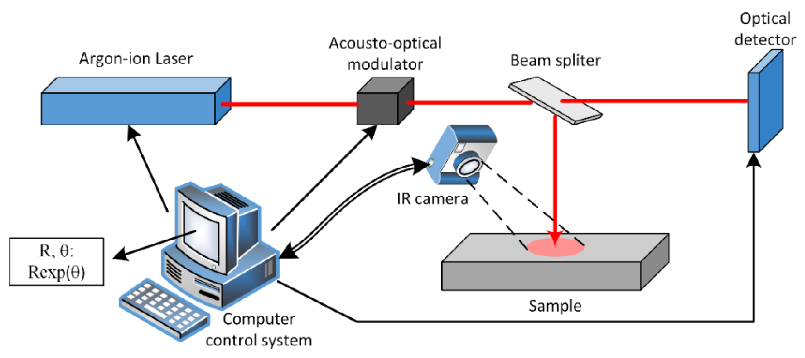
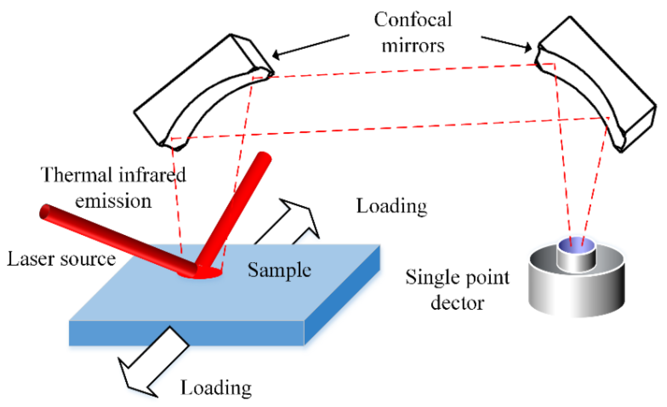
2.3. Photothermal (PT) Techniques

The discussion of PA signal dependence on the stress-strain state is based on the coupling between elastic and thermophysical properties such as density and bulk modulus, the change of which has perceptible impact on the acoustic signal. However, according to the thermodynamic theory proposed by Landau and Lifshitz [71] and Love [72], a change of stress-strain energy can affect another two groups of parameters apart from elasticity, namely, thermophysical properties [69] and the thermoelastic coupling coefficient [73,74]. Therefore, it is possible to determine the mechanical performance of a material remotely by examining its thermal property changes by means of, e.g., thermal infrared detectors.
The earliest implementation of this relationship is found in a patented instrumentation system named Stress Pattern Analysis by measurement of Thermal Emission, or SPATE [75]. A sample under test is fixed on a repetitive loading machine which provides a constant strain rate. The temperature associated with the strain energy change is measured with an infrared detector. The measurement is based on the relation between temperature and stress level described in Equation (6) and as a result a quantitative measurement of stress can materialize [76]. SPATE is a passive infrared thermographic (IT) system that does not require pumping external energy: the thermal radiation is the result of stress work in the sample. In 1988, Wong et al. reported that IT method can also be used for characterizing static loading in addition to cyclic loading state such as in a SPATE system [77]. They exerted a static bending load on an aluminum plate and captured thermographic images with an infrared camera. By analyzing the images before and after static deformation, they validated the possibility of detecting residual stress in metallic materials [77]. Similar tests were carried out for thermographical residual stress analysis in titanium alloys in NASA by Gyekenyesi and Baaklini [78]. Quinn et al. tested a series of steel and aluminum alloys with a commercial tensile machine and an IT setup. The thermoelastic signal even showed a qualitative stress distribution around holes on plates [79]. For hyper-elastic materials such as polymers, the use of passive IT can also diagnose residual stress and fatigues in them [80]. More recently, the development of NDT in reinforced composites drew the attention of a number of researchers. When the laminated structure was subjected to high levels of tensile, bending and torsional loading, the formation of internal delamination and micro cracks occurred along with energy release. By observing thermal infrared emission with a camera, IT techniques enables inspection of a whole piece of material and analysis of the inelastic stress-strain performance [81,82].
Generally, the heat equation in the presence of static stress can be derived from the first law of thermodynamics, which has the following form [70,83,84,85]:
ρ C T t ( k i i J i i 2 2 T x i 2 δ i j + ( 1 δ i j ) ( k i j + k j i ) J i i J j j 2 T x i x j ) = g
where, Jij is a Jacobian indicating the coordinate transformation due to loading (repeated subscripts denote summation), g is the source term and kij is the thermal conductivity tensor. It can be shown that the thermal conductivity tensor has a direct connection with the static stress-strain state [45,60,71,83]. As a result, instead of the SPATE mode which is suitable for evaluating cyclic loading, the static stress-strain performance can be determined based on thermal anisotropy analysis [85,86] with a proper heat source, usually a laser, which brings photothermal (PT) techniques into this consideration. Compared with PA techniques, PT detection decouples the stress-strain dependence of many physical properties by focusing only on thermal fields. The PT testing modality is local, quantitative, and absolutely noncontact.
Photothermal radiometry (PTR) is an active infrared emission testing modality. High power lasers are typically used to generate transient or harmonic local heating in solid and liquid samples, followed by free diffusion or convection. Monitoring the behavior of the diffusing field, the thermophysical properties can be evaluated. Since the 1980s, Long et al. [87,88], Milner et al. [89,90], Busse et al. [91] and Mandelis et al. [92,93,94] have reported on a series of PT-NDT techniques and applications, mainly for measuring thermophysical properties. The first report on mechanical performance monitoring published by Yarai et al. [95] used a pyroelectric device to capture the thermal field and evaluate the residual stress. The system was simple but could not achieve fully noncontact detection. Pron et al. [96,97] constructed a totally noncontact system using an Ar-ion laser and an infrared camera to generate and record the PT field on a stressed sample as shown in Figure 7. The beam splitter in that figure ensured most of the laser power was directed to the sample while an optical detector provided a reference signal for amplitude and phase data acquisition. The relative change in thermal conductivity was calculated based on the diffusion field amplitude and phase images. For a carbon steel sample, a few percent change in its thermal conductivity was found in the direction paralleled to the uniaxial loading within the elastic regime [96]. Based on a similar setup, Paoloni et al. examined the PT signal of a plastically deformed metal sample [98]. The sample was stretched to fracture so that a high level of residual stress was distributed non-uniformly around the failure surface. The diffusivity changed as much as 65% between the fracture region and the surrounding intact part. Mzali et al. used a halogen lamp instead of a laser to test the change in thermal properties of a plastically deformed metal subjected to tensile loading [99]. Since the test was continuous, a thermocouple was attached to the sample surface to measure the temperature. The contact measurement makes the system inflexible and rigid. An elastic-to-plastic full-range tensile photo-thermo-mechanical radiometry (PTMR) test was carried out by Huan et al. using both a Mercury Cadmium Telluride (MCT) detector (single point measurement, shown in Figure 8 [100] and an infrared camera for imaging [84]. In those systems, a fiber-coupled high power diode laser was used to provide more operational flexibility. The pump laser was configured at oblique incidence and the tested data were processed with a normalization algorithm. The results are shown in Figure 9. The stress-strain relation of full-range tensile loading was plotted as a function of the thermal parameter κ which is defined as the sample thickness over square-root of thermal diffusivity. The curves show a good analogy with the conventional stress-strain relation and the relative change of thermal conductivity is at the same level as [97]. The aforementioned PTMR development shows the possibility of using a PTR setup as a non-contact strain gauge.
In addition to regular metallic materials, polymers and composites are also treated with PT techniques to assess their mechanical performance, especially after plastic deformation occurs. Wang and Wright studied the change of polymer thermal diffusivity in the plastically deformed range [101]. They derived the principal diffusivity tensor as a function of the Cauchy-Green deformation tensor. A much more conspicuous change in diffusivity was observed in polymers compared with metals as expected. However, such change is reversible because of the hyperelasticity of polymers. Huan et al. further used a single point PTR configuration to test nano-coated aluminum composites [102]. A linear dependence of thermal diffusivities on the load level was found within the elastic regime and only a minimal 0.6% diffusivity change occurred the in nano-coated samples. Based on these reports, the PTMR research was extended to a number of complex materials and structures with different elasticity. Mechanical properties of intact, defective and multi-structured samples were evaluated by studying the stability of thermo-mechanical parameters under loading.
Photothermal techniques have advantages over other methods in characterizing stress-strain relations. Compared with PA, PTMR detection usually evaluates mechanical performance through diffusivity changes. Coupling between thermoelastic properties can be completely separated and the mechanical stress-strain relation can be represented by a single parameter. In addition, dynamic PT techniques generate thermal-wave fields inside a sample where the effective thermal diffusion length can be controlled by the modulation frequency or the delay time of the photothermal source which can be made to impinge on specific locations and thus can be more sensitive to regionally distributed stresses. The use of continuous wave lasers and thermal infrared detectors and cameras makes the PTMR methodology totally non-contact. Nevertheless, PT techniques analyze the thermophysical properties by sensing thermal-wave field changes and thus are time consuming and optimally performing when confocal optical systems are used which can be complicated and expensive.

3. Conclusions

Nondestructive stress-strain characterization is of fundamental importance in modern industry for the early diagnosis of mechanical failure and prediction of safety issues. Many new nondestructive testing methodologies for mechanical performance assessment of industrial manufactured parts have been developed since the first application of X-ray tomography machines for industrial component residual stress monitoring in the 1940s. This article has reviewed three categories of typical NDT/NDE approaches which have their own unique features toward characterizing the stress-strain state. The highlights and drawbacks of each method were discussed by reviewing the development history and some results from state-of-the-art research. A brief summary is listed in Table 1 for each testing method.
In future, the following points should be considered to further boost related technologies and in-field applications:
Stress-strain imaging and distribution reconstruction. Until now most reports on mechanical measurements are based on simple loaded state configurations such as hydrostatic or uniaxial loading. Unfortunately, they are insufficient for dealing with real-world stress-strain conditions. New mathematical modeling and numerical approaches should be sought to develop in-field and quantitative stress distribution analyses.
Involvement of artificial intelligence (AI) and big data (BD) technologies in NDT. Multiphysical interfaces allow inputs of data from different physical fields. This approach incorporates advantages of various processes and can bring to bear testing of different properties such as thermal, optical, elastic etc. More data may be generated from a single group of tests and provide more powerful assistance in industrial applications. AI and BD technologies such as deep-learning and machine-vision enable automatic and massive data analysis with reliable and quantitative outputs. They are also useful for diagnosing components of irregular shape and dimension. Pioneering works that treated cylinders, spheres, corners and wedges etc. can be found in [103,104,105,106,107].

Author Contributions

Methodology, H.H. and A.M.; resources, L.L., C.P., and X.C.; writing—original draft preparation, H.H.; writing—review and editing, J.Z.; supervision, A.M.; funding acquisition, L.L. All authors have read and agreed to the published version of the manuscript.

Funding

This research was funded by National Natural Science Foundation of China (NNSFC), grant number 61801358, 61805187 and 61727804; the NSERC Discovery grants and the Canada Research Chairs Program; the China Postdoctoral Science Foundation, grant number 2019M65346; the Fundamental Research Funds for the Central Universities, grant number JB20190412 and XJS190505; the National Key R&D Program of China, grant number 2017YFF0106705. The APC was funded by 61801358 and 2019M65346.

Acknowledgments

The authors want to acknowledge the School of Optoelectronic Science and Engineering, University of Electronic Science and Technology of China for a supporting program.

Conflicts of Interest

The authors declare no conflict of interest.

References

  1. Sposito, G.; Ward, C.; Cawley, P.; Nagy, P.B.; Scruby, C. A review of non-destructive techniques for the detection of creep damage in power plant steels. NDT&E Int. 2010, 43, 555–567. [Google Scholar]
  2. Breysse, D. Nondestructive evaluation of concrete strength: An historical review and a new perspective by combining NDT methods. Constr. Build. Mater. 2012, 33, 139–163. [Google Scholar] [CrossRef]
  3. Kamsu-Foguem, B. Knowledge-based support in Non-Destructive Testing for health monitoring of aircraft structures. Adv. Eng. Inform. 2012, 26, 859–869. [Google Scholar] [CrossRef] [Green Version]
  4. Hola, J.; Schabowicz, K. State-of-the-art non-destructive methods for diagnostic testing of building structures—Anticipated development trends. Arch. Civ. Mech. Eng. 2010, 10, 5–18. [Google Scholar] [CrossRef]
  5. Hola, J.; Beiń, J.; Sadowski, L.; Schabowicz, K. Non-destructive and semi-destructive diagnostics of concrete structures in assessment of their durability. Civ. Eng. 2015, 63, 87–96. [Google Scholar]
  6. Ibrahim, M.E. Nondestructive evaluation of thick-section composites and sandwich structures: A review. Compos. Part A-Appl. Sci. Manuf. 2014, 64, 36–48. [Google Scholar] [CrossRef]
  7. Duchene, P.; Chaki, S.; Ayadi, A.; Krawczak, P. A review of non-destructive techniques used for mechanical damage assessment in polymer composites. J. Mater. Sci. 2018, 53, 7915–7938. [Google Scholar] [CrossRef]
  8. Burte, H.M. A science base for NDE and its coupling to technology. In International Advances in Nondestructive Testing; McGonnagle, W.J., Ed.; CRC Press: Boca Raton, FL, USA, 1979; Volume 6, pp. 19–38. [Google Scholar]
  9. Adams, R.D.; Cawley, P. A review of defect types and nondestructive testing techniques for composites and bonded joints. NDT&E Int. 1988, 21, 208–222. [Google Scholar]
  10. Malhotra, V.M.; Carino, N.J. Handbook on Nondestructive Testing of Concrete; CRC Press: Boca Raton, FL, USA, 2003; pp. 1–13. [Google Scholar]
  11. Harding, J.; Wood, E.O.; Campbell, J.D. Tensile testing of materials at impact rates of strain. J. Mech. Eng. Sci. 1960, 2, 88–96. [Google Scholar] [CrossRef]
  12. Ramberg, W.; Osgood, W.R. Description of Stress-Strain Curves by Three Parameters; National Advisory Committee for Aeronautics Technical Note; NACA-TN-902; National Advisory Committee for Aeronautics: Washington, DC, USA, 1943. [Google Scholar]
  13. Hill, H.N. Determination of Stress-Strain Relations from “Offset” Yield Strength Values; National Advisory Committee for Aeronautics Technical Note; NACA-TN-927; National Advisory Committee for Aeronautics: Washington, DC, USA, 1944. [Google Scholar]
  14. McCullough, K.Y.G.; Fleck, N.A.; Ashby, M.F. Uniaxial stress-strain behaviour of aluminium alloy foams. Acta Mater. 1999, 47, 2323–2330. [Google Scholar] [CrossRef]
  15. Ling, Y. Uniaxial true stress-strain after necking. AMP J. Technol. 1996, 5, 37–48. [Google Scholar]
  16. Turner, R.C.; Fuierer, P.A.; Newnham, R.E.; Shrout, T.R. Materials for high temperature acoustic and vibration sensors: A review. Appl. Acoust. 1994, 41, 299–324. [Google Scholar] [CrossRef]
  17. Cegla, F.B.; Cawley, P.; Allin, J.; Davies, J. High-temperature (>500 °C) wall thickness monitoring using dry-coupled ultrasonic waveguide transducers. IEEE Trans. Ultrason. Ferroelectr. Freq. Control 2011, 58, 156–167. [Google Scholar] [CrossRef] [PubMed]
  18. Kobayashi, M.; Jen, C.K.; Bussiere, J.F.; Wu, K.T. High-temperature integrated and flexible ultrasonic transducers for nondestructive testing. NDT&E Int. 2009, 42, 157–161. [Google Scholar]
  19. Liu, Z.; Wu, H.; Paterson, A.; Luo, Z.; Ren, W.; Ye, Z.G. High Curie-temperature (TC) piezo-/ferroelectric single crystals with bismuth-based complex perovskites: Growth, structures and properties. Acta Mater. 2017, 136, 32–38. [Google Scholar] [CrossRef]
  20. Lyons, J.S.; Liu, J.; Sutton, M.A. High-temperature deformation measurements using digital-image correlation. Exp. Mech. 1996, 36, 64–70. [Google Scholar] [CrossRef]
  21. Anwander, M.; Zagar, B.G.; Weiss, B.; Weiss, H. Noncontacting strain measurements at high temperature by the digital laser speckle technique. Exp. Mech. 2000, 40, 98–105. [Google Scholar] [CrossRef]
  22. Vǒlkl, R.; Fischer, B. Mechanical testing of ultra-high temperature alloys. Exp. Mech. 2004, 44, 121–127. [Google Scholar] [CrossRef]
  23. Zhu, D.; Mobasher, B.; Rajan, S.D. Non-contacting strain measurement for cement-based composites in dynamic tensile testing. Cem. Concr. Compos. 2012, 34, 147–155. [Google Scholar] [CrossRef]
  24. Wolverton, M.; Bhattacharyya, A.; Kannarpady, G.K. Efficient, flexible, noncontact deformation measurements using video multi-extensometry. Exp. Tech. 2009, 33, 24–33. [Google Scholar] [CrossRef]
  25. Pan, B.; Wu, D.; Wang, Z.; Xia, Y. High-temperature digital image correlation method for full-field deformation measurement at 1200 °C. Meas. Sci. Technol. 2011, 22, 015701. [Google Scholar] [CrossRef]
  26. Pan, B.; Qian, K.; Xie, H.; Asundi, A. Two-dimensional digital image correlation for in-plane displacement and strain measurement: A review. Meas. Sci. Technol. 2009, 20, 062001. [Google Scholar] [CrossRef]
  27. Yang, X.; Liu, Z.; Xie, H. A real time deformation evaluation method for surface and interface of thermal barrier coatings during 1100 °C thermal shock. Meas. Sci. Technol. 2012, 23, 105604. [Google Scholar] [CrossRef]
  28. Hoła, J.; Sadowski, Ł.; Reiner, J.; Stach, S. Usefulness of 3D surface roughness parameters for nondestructive evaluation of pull-off adhesion of concrete layers. Constr. Build. Mater. 2015, 84, 111–120. [Google Scholar] [CrossRef]
  29. Czarnecki, S.; Hoła, J. Evaluation of the height 3D roughness parameters of concrete substrate and the adhesion to epoxy resin. Int. J. Adhes. Adhes. 2016, 67, 3–13. [Google Scholar]
  30. Sadowski, Ł. Non-destructive identification of pull-off adhesion between concrete layers. Automat. Constr. 2015, 57, 146–155. [Google Scholar] [CrossRef]
  31. Barrett, C.S.; Predecki, P. Stress measurement in graphite/epoxy uniaxial composites by X-ray. Polym. Compos. 1980, 1, 2–6. [Google Scholar] [CrossRef]
  32. Ledbetter, H.M.; Austin, M.W. Internal strain (stress) in an SiC-Al particle-reinforced composite: An X-ray diffraction study. Mater. Sci. Eng. 1987, 89, 53–61. [Google Scholar] [CrossRef]
  33. Hemley, R.J.; Mao, H.; Shen, G.; Badro, J.; Gillet, P.; Hanfland, M.; Häusermann, D. X-ray imaging of stress and strain of diamond, iron, and tungsten at megabar pressures. Science 1997, 276, 1242–1245. [Google Scholar] [CrossRef] [Green Version]
  34. Prevey, P.S. X-ray diffraction residual stress techniques. ASM Handb. 1986, 10, 380–392. [Google Scholar]
  35. Hughes, D.J.; Mahendrasingam, A.; Martin, C.; Oatway, M.B.; Heeley, E.L.; Bingham, S.J.; Fuller, W. An instrument for the collection of simultaneous small and wide angle X-ray scattering and stress–strain data during deformation of polymers at high strain rates using synchrotron radiation sources. Rev. Sci. Instrum. 1999, 70, 4051–4054. [Google Scholar] [CrossRef]
  36. Patterson, B.M.; Cordes, N.L.; Henderson, K.; Williams, J.J.; Stannard, T.; Singh, S.S.; Ovejero, A.R.; Xiao, X.; Robinson, M.; Chawla, N. In situ X-ray synchrotron tomographic imaging during the compression of hyper-elastic polymeric materials. J. Mater. Sci. 2016, 51, 171–187. [Google Scholar] [CrossRef]
  37. Fieres, J.; Schumann, P.; Reinhart, C. Predicting failure in additively manufactured parts using X-ray computed tomography and simulation. Procedia Eng. 2018, 213, 69–78. [Google Scholar] [CrossRef]
  38. Subramanian, J.; Seetharaman, S.; Gupta, M. Processing and properties of aluminum and magnesium based composites containing amorphous reinforcement: A review. Metals 2015, 5, 743–762. [Google Scholar] [CrossRef] [Green Version]
  39. Xing, J.; Zhao, C.; Yu, S.; Matsuda, H.; Ma, C. Experimental study on rock-like specimens with single flaw under hydro-mechanical coupling. Appl. Sci. 2019, 9, 3234. [Google Scholar] [CrossRef] [Green Version]
  40. Youssef, S.; Marie, E.; Gaertner, R. Finite element modelling of the actual structure of cellular materials determined by X-ray tomography. Acta Mater. 2005, 53, 710–730. [Google Scholar] [CrossRef]
  41. Bell, A.G. On the production and reproduction of sound by light. Am. J. Sci. 1880, 20, 305–324. [Google Scholar] [CrossRef] [Green Version]
  42. Scruby, C.B.; Dewhurst, R.J.; Hutchins, D.A.; Palmer, B. Quantitative studies of thermally generated elastic waves in laser-irradiated metals. J. Appl. Phys. 1981, 51, 6210–6216. [Google Scholar] [CrossRef]
  43. Rose, L.R.F. Point-source representation for laser-generated ultrasound. J. Acoust. Soc. Am. 1984, 75, 723–732. [Google Scholar] [CrossRef]
  44. Hutchins, D.A. Mechanisms of pulsed photoacoustic generation. Can. J. Phys. 1986, 64, 1247–1264. [Google Scholar] [CrossRef]
  45. Biot, M.A. The influence of initial stress on elastic waves. J. Appl. Phys. 1940, 11, 522–530. [Google Scholar] [CrossRef]
  46. Hughes, D.S.; Kelly, J.L. Second-order elastic deformation of solids. Phys. Rev. 1953, 92, 1145–1149. [Google Scholar] [CrossRef]
  47. Bergman, R.H.; Shahbender, R.A. Effect of statically applied stresses on the velocity of propagation of ultrasonic waves. J. Appl. Phys. 1958, 29, 1736–1738. [Google Scholar] [CrossRef]
  48. Tokuoka, T.; Saito, M. Elastic wave propagations and acoustical birefringence in stressed crystals. J. Acoust. Soc. Am. 1968, 45, 1241–1246. [Google Scholar] [CrossRef]
  49. Husson, D.; Kino, G.S. A perturbation theory for acoustoelastic effects. J. Appl. Phys. 1982, 53, 7250–7258. [Google Scholar] [CrossRef]
  50. Shams, M.; Destrade, M.; Ogden, R.W. Initial stresses in elastic solids: Constitutive laws and acoustoelasticity. Wave Motion 2011, 48, 552–567. [Google Scholar] [CrossRef] [Green Version]
  51. Davies, G.F. Quansi-harmonic finite strain equations of state of solids. J. Phys. Chem. Solids 1973, 34, 1417–1429. [Google Scholar] [CrossRef]
  52. Murnaghan, F.D. Finite deformations of an elastic solid. Am. J. Math. 1937, 59, 235–260. [Google Scholar] [CrossRef]
  53. Tylczyński, Z.; Mróz, B. The influence of uniaxial stress on ultrasonic wave propagation in ferroelastic (NH4)4LiH3(SO4)4. Solid State Commun. 1997, 101, 653–656. [Google Scholar] [CrossRef]
  54. Chaki, S.; Bourse, G. Guided ultrasonic waves for non-destructive monitoring of the stress levels in prestressed steel strands. Ultrasonics 2009, 49, 162–171. [Google Scholar] [CrossRef]
  55. Gennisson, J.L.; Renier, M.; Catheline, S.; Barriere, C.; Bercoff, J.; Tanter, M.; Fink, M. Acoustoelasticity in soft solids: Assessment of the nonlinear shear modulus with the acoustic radiation force. J. Acoust. Soc. Am. 2007, 122, 3211–3219. [Google Scholar] [CrossRef] [PubMed]
  56. Iwashimizu, Y.; Kobori, O. The Rayleigh wave in a finitely deformed isotropic elastic material. J. Acoust. Soc. Am. 1978, 64, 910–916. [Google Scholar] [CrossRef]
  57. Duquennoy, M.; Ouaftouh, M.; Deboucq, J.; Lefebvre, J.E.; Jenot, F.; Ourak, M. Influence of a superficial field of residual stress on the propagation of surface waves—Applied to the estimation of the depth of the superficial stressed zone. Appl. Phys. Lett. 2012, 101, 234104. [Google Scholar] [CrossRef]
  58. Duquennoy, M.; Ouaftouh, M.; Ourak, M.; Jenot, F. Theoretical determination of Rayleigh wave acoustoelastic coefficients: Comparison with experimental values. Ultrasonics 2002, 39, 575–583. [Google Scholar] [CrossRef]
  59. Kasai, M.; Sawada, T. Non-destructive evaluation of the distribution of stress by means of the photoacoustic microscope. In Photoacoustic and Photothermal Phenomena II; Murphy, J.C., Maclachlan Spicer, J.W., Aamodt, L.C., Royce, B.S.H., Eds.; Springer: Berlin, Germany, 1990; pp. 33–36. [Google Scholar]
  60. Muratikov, K.L.; Glazov, A.L.; Rose, D.N.; Dumar, J.E. Photoacoustic effect in stressed elastic solids. J. Appl. Phys. 2000, 88, 1948–2955. [Google Scholar] [CrossRef]
  61. Muratikov, K.L. Theory of stress influence on the photoacoustic thermoelastic signal near the vertical crack tips. Rev. Sci. Instrum. 2003, 74, 722–724. [Google Scholar] [CrossRef]
  62. Muratikov, K.L. Theory of the generation of mechanical vibrations by laser radiation in solids containing internal stresses on the basis of the thermoelastic effect. Tech. Phys. 1999, 44, 792–796. [Google Scholar] [CrossRef]
  63. Keller, J.B. Finite elastic deformation governed by linear equations. J. Appl. Mech. 1986, 53, 819–820. [Google Scholar] [CrossRef]
  64. Huan, H.; Mandelis, A.; Lashkari, B.; Liu, L. Frequency-domain laser ultrasound (FDLU) non-destructive evaluation of stress-strain behavior in an aluminum alloy. Int. J. Thermophys. 2017, 38, 62. [Google Scholar] [CrossRef]
  65. Sun, G.; Zhou, Z. Non-contact detection of delamination in layered anisotropic composite materials with ultrasonic waves generated and detected by lasers. Optik 2016, 127, 6424–6433. [Google Scholar] [CrossRef]
  66. Karabutov, A.; Devichensky, A.; Ivochkin, A.; Lyamshev, M.; Pelivanov, I.; Rohdgi, U.; Solomatin, V.; Subudhi, M. Laser ultrasonic diagnostics of residual stress. Ultrasonics 2008, 48, 631–635. [Google Scholar] [CrossRef] [PubMed]
  67. McDonald, W.F.; Goettler, H.; Urban, M.W. A novel approach to photoacoustic FT-IR spectroscopy: Rheo-photoacoustic measurements. Appl. Spectrosc. 1989, 43, 1387–1393. [Google Scholar] [CrossRef]
  68. Liu, L.; Mandelis, A.; Huan, H.; Melnikov, A. Step-scan T cell-based differential Fourier transform infrared photoacoustic spectroscopy (DFTIR-PAS) for detection of ambient air contaminants. Appl. Phys. B 2016, 122, 268. [Google Scholar] [CrossRef]
  69. Liu, L.; Mandelis, A.; Huan, H.; Michaelian, K.H. Step-scan differential Fourier transform infrared photoacoustic spectroscopy (DFTIR-PAS): A spectral deconvolution method for weak absorber detection in the presence of strongly overlapping background absorptions. Opt. Lett. 2017, 42, 1424–1427. [Google Scholar] [CrossRef] [PubMed]
  70. Qian, M. New thermoelastic technique for detection of residual stress distribution in solids. Acta Acust. 1995, 14, 97–106, (Chinese Version). [Google Scholar]
  71. Landau, L.D.; Lifshitz, E.M. Theory of Elasticity; Pergamon: Oxford, UK, 1959; pp. 119–121. [Google Scholar]
  72. Love, A.E.H. A Treatise on the Mathematical Theory of Elasticity, 2nd ed.; Cambridge University Press: Cambridge, UK, 1906; pp. 90–107. [Google Scholar]
  73. Wong, A.K.; Jones, R.; Sparrow, J.G. Thermoelastic constant or thermoelastic parameter? J. Phys. Chem. Solids 1987, 48, 749–753. [Google Scholar] [CrossRef]
  74. Wong, A.K.; Sparrow, J.G.; Dunn, S.A. On the revised theory of the thermoelastic effect. J. Phys. Chem. Solids 1988, 49, 395–400. [Google Scholar] [CrossRef]
  75. Belgen, M.H. Structural stress measurements with an infrared radiometer. ISA Trans. 1967, 6, 49–53. [Google Scholar]
  76. Stanley, P.; Chan, W.K. Quantitative stress analysis by means of the thermoelastic effect. J. Strain Anal. Eng. 1985, 20, 129–137. [Google Scholar] [CrossRef]
  77. Wong, A.K.; Dunn, S.A.; Sparrow, J.G. Residual stress measurement by means of the thermoelastic effect. Nature 1988, 332, 613–615. [Google Scholar] [CrossRef]
  78. Gyekenyesi, A.L.; Baaklini, G.Y. Thermoelastic stress analysis: The mean stress effect in metallic alloys. In Proceedings of the Nondestructive Evaluation Techniques for Aging Infrastructures and Manufacturing, Newport Beach, CA, USA, 3–5 March 1999. NASA/TM-1999-209376. [Google Scholar]
  79. Quinn, S.; Dulieu-Barton, J.M.; Langlands, J.M. Progress in thermoelastic residual stress measurement. Strain 2004, 40, 127–133. [Google Scholar] [CrossRef]
  80. Menczel, J.D.; Prime, R.B. Thermal Analysis of Polymers Fundamentals and Applications; John Wiley & Sons: Hoboken, NJ, USA, 2009; pp. 384–495. [Google Scholar]
  81. Zhang, H.; Sfarra, S.; Sarasini, F.; Santulli, C.; Fernandes, H.; Avdelidis, N.P.; Ibarra-Castanedo, C.; Maldague, X.P.V. Thermographic non-destructive evaluation for natural fiber-reinforced composite laminates. Appl. Sci. 2018, 8, 240. [Google Scholar] [CrossRef] [Green Version]
  82. Liu, J.; Gong, J.; Liu, L.; Qin, L.; Wang, Y. Investigation on stress distribution of multilayered composite structure (MCS) using infrared thermographic technique. Infrared Phys. Technol. 2013, 61, 134–143. [Google Scholar] [CrossRef]
  83. Huan, H.; Mandelis, A.; Liu, L. Characterization of the mechanical stress–strain performance of aerospace alloy materials using frequency-domain photoacoustic ultrasound and photothermal methods: An FEM approach. Int. J. Thermophys. 2018, 39, 55. [Google Scholar] [CrossRef]
  84. Huan, H.; Mandelis, A.; Liu, L.; Melnikov, A. Local-stress-induced thermal conductivity anisotropy analysis using non-destructive photo-thermo-mechanical lock-in thermography (PTM-LIT) imaging. NDT&E Int. 2017, 91, 79–87. [Google Scholar]
  85. Salazar, A.; Sanchez-Lavega, A.; Ocariz, A.; Guitonny, J.; Pandey, G.C.; Fournier, D.; Boccara, A.C. Thermal diffusivity of anisotropic materials by photothermal methods. J. Appl. Phys. 1996, 79, 3984–3993. [Google Scholar] [CrossRef]
  86. Iravani, M.V.; Nikoonahad, M. Photothermal waves in anisotropic media. J. Appl. Phys. 1987, 62, 4065–4071. [Google Scholar] [CrossRef]
  87. Long, F.H.; Anderson, R.R.; Deutsch, T.F. Pulsed photothermal radiometry for depth profiling of layered media. Appl. Phys. Lett. 1987, 51, 2076–2078. [Google Scholar] [CrossRef]
  88. Prahl, S.A.; Vitkin, I.A.; Bruggemann, U.; Wilson, B.C.; Aderson, R.R. Determination of optical properties of turbid media using pulsed photothermal radiometry. Phys. Med. Biol. 1992, 37, 1203–1217. [Google Scholar] [CrossRef]
  89. Milner, T.E.; Smithies, D.J.; Goodman, D.M.; Lau, A.; Nelson, J.S. Depth determination of chromophores in human skin by pulsed photothermal radiometry. Appl. Opt. 1996, 35, 3379–3385. [Google Scholar] [CrossRef]
  90. Milner, T.E.; Katzir, A.; Jacques, S.L. Pulsed photothermal radiometry of port-wine stains. Proc. SPIE 1993, 1882, 34–42. [Google Scholar]
  91. Busse, G.; Wu, D.; Karpen, W. Thermal wave imaging with phase sensitive modulated thermography. J. Appl. Phys. 1992, 71, 3962–3965. [Google Scholar] [CrossRef]
  92. Mandelis, A.; Abrams, S.H.; Nicolaides, L.; Garcia, J.A. Method and Apparatus for Detection of Defects in Teeth. U.S. Patent US6584341, 24 June 2003. [Google Scholar]
  93. Wang, C.; Mandelis, A.; Liu, Y. Thermal-wave nondestructive evaluation of cylindrical composite structures using frequency-domain photothermal radiometry. J. Appl. Phys. 2005, 97, 014911. [Google Scholar] [CrossRef] [Green Version]
  94. Balderas-López, J.A.; Mandelis, A.; Garcia, J.A. Thermal-wave resonator cavity design and measurements of the thermal diffusivity of liquids. Rev. Sci. Instrum. 2000, 71, 2933–2937. [Google Scholar] [CrossRef]
  95. Yarai, A.; Yokoyama, Y.; Nakanishi, T. New non-destructive photothermal measurement of anisotropically distributed residual stress inside samples. In Proceedings of the IEEE Ultrasonics Symposium, Cannes, France, 31 October–3 November 1994; pp. 683–686. [Google Scholar]
  96. Pron, H.; Henry, J.F.; Offermann, S.; Bissieux, C.; Beaudoin, J.L. Analysis of stress influence on thermal diffusivity by photothermal infrared thermography, Estimation of local thermophysical properties by means of front-face photothermal infrared thermography: Application to mechanical stress analysis. High Temp.-High Press. 2000, 32, 473–477. [Google Scholar] [CrossRef]
  97. Pron, H.; Bissieux, C. 3-D thermal modelling applied to stress-induced anisotropy of thermal conductivity. Int. J. Therm. Sci. 2004, 43, 1161–1169. [Google Scholar] [CrossRef]
  98. Paoloni, S.; Tata, M.E.; Scudieri, F.; Mercuri, F.; Marinelli, M.; Zammit, U. IR thermography characterization of residual stress in plastically deformed metallic components. Appl. Phys. A 2010, 98, 461–465. [Google Scholar] [CrossRef]
  99. Mzali, F.; Albouchi, F.; Nasrallah, S.B.; Petit, D. Optimal experiment design and thermo-physical characterization of a plastically deformed solid. Inverse Probl. Sci. Eng. 2009, 17, 335–345. [Google Scholar] [CrossRef]
  100. Huan, H.; Mandelis, A.; Liu, L.; Melnikov, A. Non-destructive and non-contacting stress-strain characterization of aerospace metallic alloys using photo-thermo-mechanical radiometry. NDT&E Int. 2016, 84, 47–53. [Google Scholar]
  101. Wang, Y.; Wright, N.T. A relationship between thermal diffusivity and finite deformation in polymers. Int. J. Thermophys. 2005, 26, 1849–1859. [Google Scholar] [CrossRef]
  102. Huan, H.; Mandelis, A.; Liu, L.; Melnikov, A. Evaluation of mechanical performance of NiCo nanocoated aerospace aluminum alloy using quantitative photo-thermo-mechanical radiometry as a non-contact strain gauge. NDT&E Int. 2017, 87, 44–49. [Google Scholar]
  103. Tai, R.; Zhang, J.; Wang, C.; Mandelis, A. Thermal-Wave Fields in Solid Wedges Using the Green Function Method: Theory and Experiment. J. Appl. Phys. 2013, 113, 133501. [Google Scholar] [CrossRef] [Green Version]
  104. Liu, L.; Wang, C.; Yuan, X.; Mandelis, A. Curvature-insensitive methodology for thermal-wave depth-profilometry in curvilinear solids. J. Phys. D-Appl. Phys. 2010, 43, 285403. [Google Scholar] [CrossRef]
  105. Celorrio, R.; Mendioroz, A.; Apiñaniz, E.; Salazar, A.; Wang, C.; Mandelis, A. Reconstruction of radial thermal conductivity depth profile in case hardened steel rods. J. Appl. Phys. 2009, 105, 083517. [Google Scholar] [CrossRef]
  106. Zhang, J.; Xie, G.; Wang, C.; Mandelis, A. Laser induced thermal-wave fields in multi-layered spherical solids based on Green function method. J. Appl. Phys. 2012, 112, 033521. [Google Scholar] [CrossRef]
  107. Wang, M.; Mandelis, A.; Melnikov, A.; Wang, C. Quantitative lock-in thermography imaging of thermal-wave spatial profiles and thermophysical property measurements in solids with inner corner geometries using thermal-wave field theory. J. Appl. Phys. 2018, 124, 205106. [Google Scholar] [CrossRef]
Figure 1. The schematic of digital-image correlation (DIC) strain evaluation.
Applsci 10 01588 g001
Figure 2. Strain measurement configuration with blue light source, redrawn from [24].
Applsci 10 01588 g002
Figure 3. Scheme of residual stress detection by X-ray diffraction.
Applsci 10 01588 g003
Figure 4. Stress measurement scheme by pulsed ultrasound.
Applsci 10 01588 g004
Figure 5. The scanning photoacoustic signal amplitude change. The visible defect is between 0 and 97 µm (“X” marking); reproduced from [60] with permission from The American Institute of Physics © 2000.
Applsci 10 01588 g005
Figure 6. PA stress-strain test schematic with water coupling (left) and the stress-strain curve on the basis of PA phase (right); reproduced from [64] with permission from Springer Nature © 2017.
Applsci 10 01588 g006
Figure 7. Schematic of a lock-in photothermal technique for stress-strain evaluation, redrawn based on [97].
Applsci 10 01588 g007
Figure 8. Schematic of lock-in photo-thermo-mechanical radiometry (PTMR) testing with a single-point detector and a confocal radiation collection system, redrawn based on [100].
Applsci 10 01588 g008
Figure 9. Composite thermal parameter κ as a function of strain that shows good analogy with a typical engineering stress-strain curve, reproduced from [100] with permission from Elsevier © 2016.
Applsci 10 01588 g009
Table 1. Summary of popular stress-strain NDT/NDE methods.
CategoryMethodologyPhysical FieldSystem ComplexityContact/Non-ContactMeasurement Range
Optical/radiativeDICElectromagneticLowNon-contactSurface only
X-rayElectromagneticHighNon-contactInternal
AcousticPure acousticElasticLowContactSurface/internal
PAThermoelasticMediumSemi-/total-noncontactSurface/internal
ThermalSPATEElectromagneticMediumNon-contactAverage
PTMRElectromagneticLowNon-contactSurface/internal

