Article

Development of a Low Cost and Path-free Autonomous Patrol System Based on Stereo Vision System and Checking Flags

Department of Electrical and Electronic Engineering, Chung Cheng Institute of Technology, National Defense University, No. 75, Shiyuan Rd., Daxi District, Taoyuan City 33551, Taiwan
*
Author to whom correspondence should be addressed.
Appl. Sci. 2020, 10(3), 974; https://doi.org/10.3390/app10030974
Submission received: 10 January 2020 / Revised: 27 January 2020 / Accepted: 31 January 2020 / Published: 2 February 2020
(This article belongs to the Special Issue Applications of Intelligent Control Methods in Mechatronic Systems)

Abstract

:
Nowadays, security guard patrol services are becoming roboticized. However, high construction prices and complex systems make patrol robots difficult to be popularized. In this research, a simplified autonomous patrolling robot is proposed, which is fabricated by upgrading a wheeling household robot with stereo vision system (SVS), radio frequency identification (RFID) module, and laptop. The robot has four functions: independent patrolling without path planning, checking, intruder detection, and wireless backup. At first, depth information of the environment is analyzed through SVS to find a passable path for independent patrolling. Moreover, the checkpoints made with RFID tag and color pattern are placed in appropriate positions within a guard area. While a color pattern is detected by the SVS, the patrolling robot is guided to approach the pattern and check its RFID tag. For more, the human identification function of SVS is used to detect an intruder. While a skeleton information of the human is analyzed by SVS, the intruder detection function is triggered, then the robot follows the intruder and record the images of the intruder. The recorded images are transmitted to a server through Wi-Fi to realize the remote backup, and users can query the recorded images from the network. Finally, an experiment is made to test the functions of the autonomous patrolling robot successfully.

1. Introduction

Home security has always been an issue for everyone. However, hiring security guards involves high costs, and also issues of safety about acquaintances. On the other hand, sweeping robots have gradually become commonplace in every home environment. If there is a simple and low-cost method that can increase the patrol function on traditional sweeping robots, it will effectively solve the problem of home security. The patrol system is highly dependent on the function of simultaneous localization and mapping (SLAM), and it also needs rapid SLAM execution efficiency. Therefore, much research has been devoted to improving the working efficiency of SLAM [1,2,3,4,5,6]. Lee, C.W. et al. proposed a variable size rectangle region to replace the traditional grid method of SLAM, and the proposed method reduces the data storage capacity of built maps [1]. Dwijotomo, A. et al. use the adaptive multistage distance scheduler (AMDS) method to improve the working speed of SLAM with large map size. [2]. Li, X. et al. proposed a monocular vision fast 3D SLAM system by using a fusion of localization, mapping, and parses scenes [3,4]. In addition, Valiente, D. et al. also used an omnidirectional monocular sensor to improve the stability of SLAM [5]. Muñoz–Bañón, M.Á. et al. proposed a novel navigation framework based on the robot operation system (ROS), which can separate a mission into several sub-issues to solve them to improve the SLAM working efficiency [6]. Moreover, numerous researchers have addressed the issue of autonomous patrolling robots [7,8,9]. Li et al. employed a Kinect depth sensor with the type-1 and type 2 fuzzy controller to overcome the problem of exploring the environment [7]. In addition, they also used ultrasonic sensors and fuzzy sensor fusion technology to fabricate a map of the environment [8]. Cherubini et al. used LiDAR and a Kalman-based algorithm for navigation [9]. In the above study, ultrasonic sensors are inexpensive but lack accuracy, whereas LiDAR is accurate but expensive. Thus, we selected depth sensors in the current research.
On the other hand, given that the accuracy of SLAM is based on the precision of sensors, and the precision is sometimes related to the price of sensors, several researches are focus on how to cost down patrol systems [10,11,12,13,14,15,16,17,18,19,20,21,22,23]. Jiang, G. et al. propose a graph optimization-based SLAM framework through combining a low-cost LiDAR and an RGB-D camera to improve the defect of accumulated error for building large maps only by low-cost LiDAR [10,11,12,13]. Same for in order to reduce the cost of using high prices LiDAR, Jiang, G. et al. propose a fast Fourier transform-based scan-match method to enhance the accuracy and resolution of a low-cost LiDAR [14]. Moreover, Shuda L. used only an RGB-D camera to realize the SLAM application [15,16,17]. For more, Gong Z. et al. combine a cheap LiDAR system and crash sensors with a NVIDIA Jetson tk1 module on a wheeling robot to fabricate a low cost patrolling platform, and using tiny SLAM algorithm on the platform to achieve a real-time indoor mapping [18]. Anandharaman S. et al. use a monocular camera with large-scale direct monocular SLAM (LSD-SLAM) method on unmanned aerial vehicle to realize a low-cost navigation and mapping system [19]. Xi W. et al. use RPLiDAR on iRobot with Lenovo G470 laptop to build an experimental facility. The one dimensional Fourier transformation is used to build a map from cloud dots measured which is measured by RPLiDAR [20]. Fang Z. et al. use a 2D laser scanner which is driven by a stepper to make a SLAM system. They reduce the local drift of measured cloud data by using a coarse-to-fine graph optimization method of a local map, and solve the global drift problem by an explicit loop closing heuristic (ELCH) and a general framework for optimization (G2O) methods [21]. Bae H. et al. use Bluetooth low energy (BLE) with constrained extended Kalman filter to realize a low-cost indoor positioning system [22], and DiGiampaolo E. et al. also use passive UHF-radio frequency identification (RFID) to aid the localizing accuracy of SLAM [23].
Moreover, several proposed methods focus on how to locate and find the patrol path in a known environment. Chen et al. proposed the SIFT method to define the features of images by which to guide a robot while patrolling [24]. Song et al. used multiple transient radio sources to locate the mobile robot and plan a path, and using the Monte Carlo method to solve the problem of capturing and analyzing the radio signals [25]. Chen, X. et al. propose a sound source based landmark for SLAM [26]. A robot with a built-in audio source is used in the research to interact with microphone arrays which are at known coordinates in the environment to locate the robot itself. Wang, Z. et al. propose an IMU-Assisted SLAM method to improve the localization accuracy of 2D LiDAR by using extended Kalman filter [27]. An V. et al. propose a path planning method that a patrol robot can re-plan a patrol path from sufficient number of observation points while meets dynamic obstacles [28]. However, the expense of setting up and maintaining numerous signal emitting sources led us to select the image analysis method to locate a path in this study. Moreover, we referenced the work of Huang et al. [29] and Yu et al. [30] to realize the functions of patrolling check-ins and intruder detection. In the research of Huang et al., the RFID indoor positioning system was visualized using geographic coordinates. They also used the architecture of an RFID indoor positioning system for the installation of checkpoints. In the research of Yu et al., they used an infrared sensor array to enable mobile robots to track and follow humans.
Finally, besides functions of SLAM for patrolling, the system outlined by Hung et al. [31] is used in our research for the backing up of patrolling data and making internet queries. Though web service is not the latest technology, it remains useful for regional network communication. To reduce data transmission, Lian et al. propose an embedded spatial coding method, which assigns weights to objects of interest [32]. In this study, images of intruders are encoded and then transmitted for backing up.
The remainder of this paper is organized as follows. In Section 2, we introduce the system architecture. In Section 3, the algorithm used to direct all patrolling functions is explained. Experiment results and a brief discussion are presented in Section 4. Conclusions are made in Section 5.

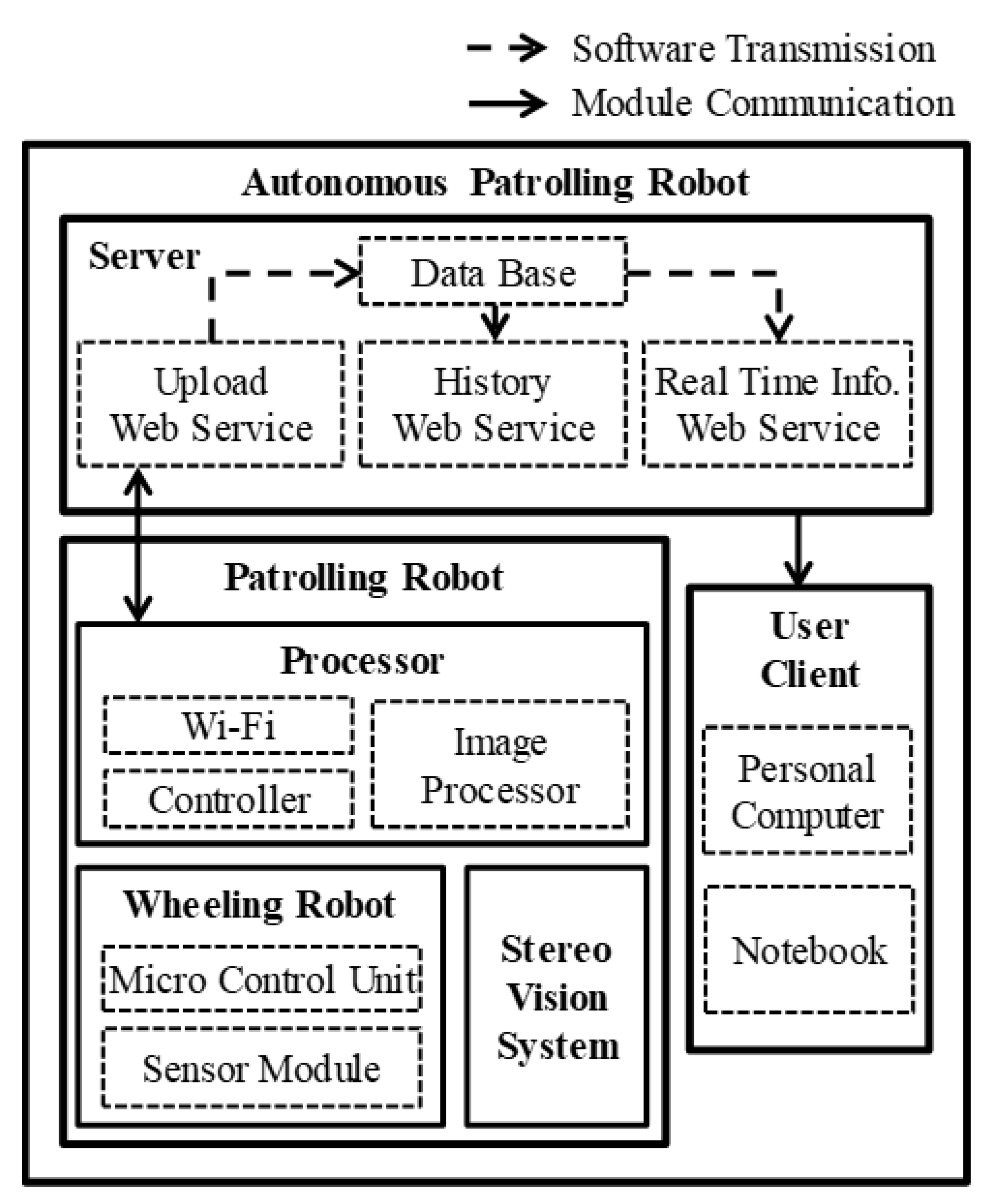
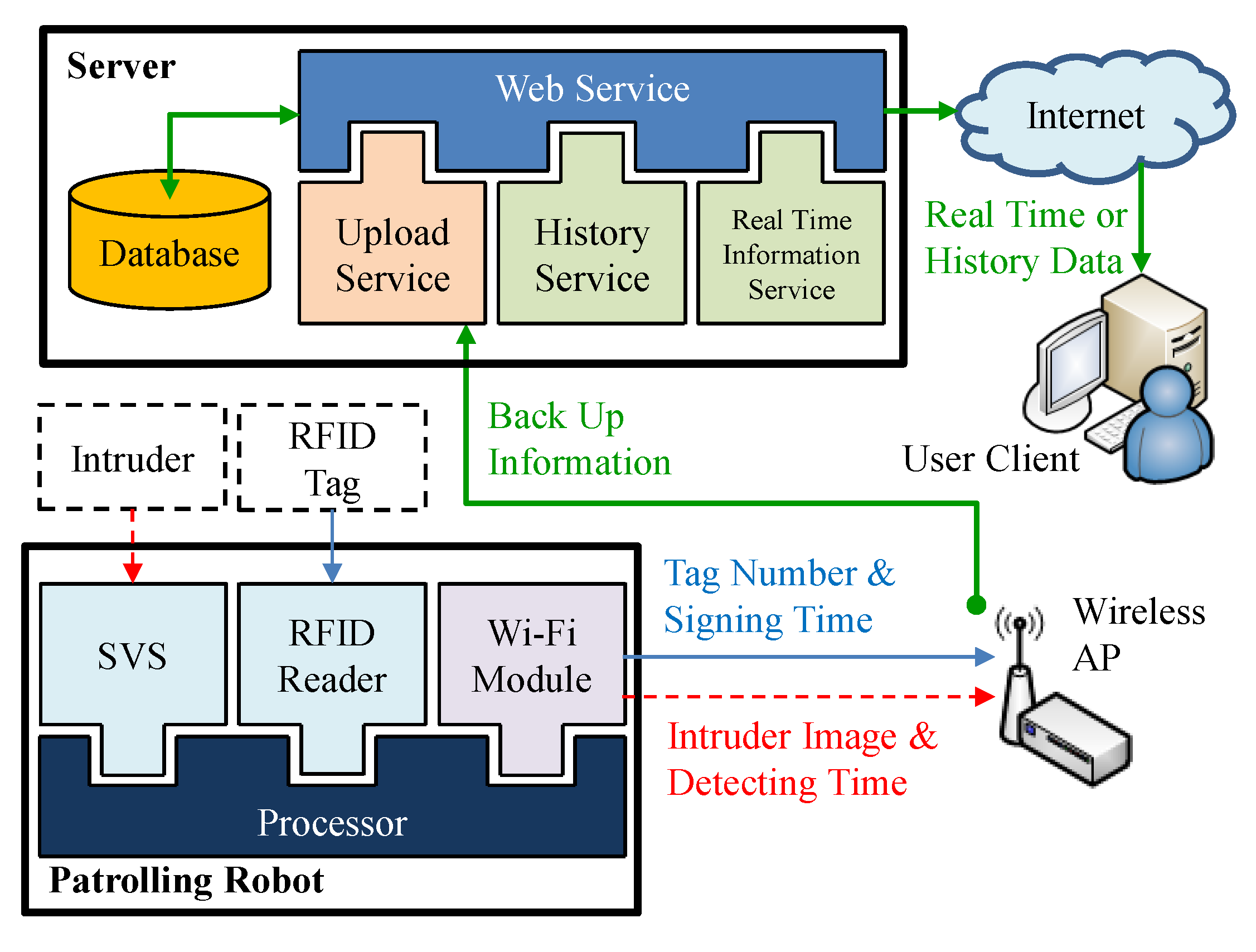
2. System Architecture
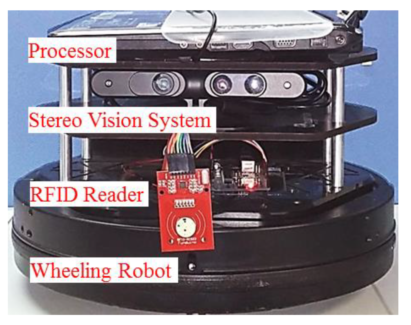
The three basic components of the system include a patrol robot, server, and client, as shown in Figure 1. The system architecture of each component is outlined in the following.

2.1. Patrol Robot

The patrol robot comprises of a processor, wheeled robot, and stereo vision system (SVS). An ASUS K401D notebook running Windows 7 was used as a processor. USB-connected ASUS Xtion pro live was used as an SVS to provide color images and depth information. Owing to that the depth information provided by SVS is based on its active infrared sensor, and the sensor is very sensitive to sun ray, the proposed system in this research just can be used indoors. The wheeled robot was built by integrating a KOBUKI robot, a product that is designed for programmable control without default functions, and an RFID system using an Arduino Uno R3 controller. Depth information of the environment captured by the SVS is analyzed by the processor to find a suitable path. The direction of movement is transformed into commands controlling the robot. The SVS continues monitoring the environment in order to make adjustments to the path in real-time. The cliff sensor, wheel drop sensor, and bumpers of the KOBUKI are also used to modify the patrol path. The SVS also seeks out inspection points and detects intruders. The robot is programmed to approach the inspection points and follow intruders until they disappear. All of this information is transmitted to a database via Wi-Fi. The structure of the proposed robot is presented in Figure 2.

2.2. Server

A server is used to provide the Windows communication foundation (WCF) web-service and a database for remote image backup. We developed three web-services: upload, history, and real-time. The upload web-service is used for the transmission of information to the server, including inspection point number, check-in time, time of intruder detection, and images of intruder. Remote users can access historical data by scan time and monitor the robot in real-time. The database was built using Microsoft SQL server 2008, and the web-service was built using Visual Studio C# 2010.

3. Materials and Methods

The robot first searches for a passable path using depth information from the SVS. While on patrol, the robot follows any detected intruder, takes an image of the individual, and uploads the images in real-time. The robot approaches all detected inspection points and signs in electronically, whereupon the inspection point number and sign-in time are uploaded. When all of the inspection points have been passed, that particular patrolling task is complete. Figure 3 presents a flowchart showing the process of autonomously patrolling a site. In the following section, we introduce the four functions controlled by the proposed algorithm.

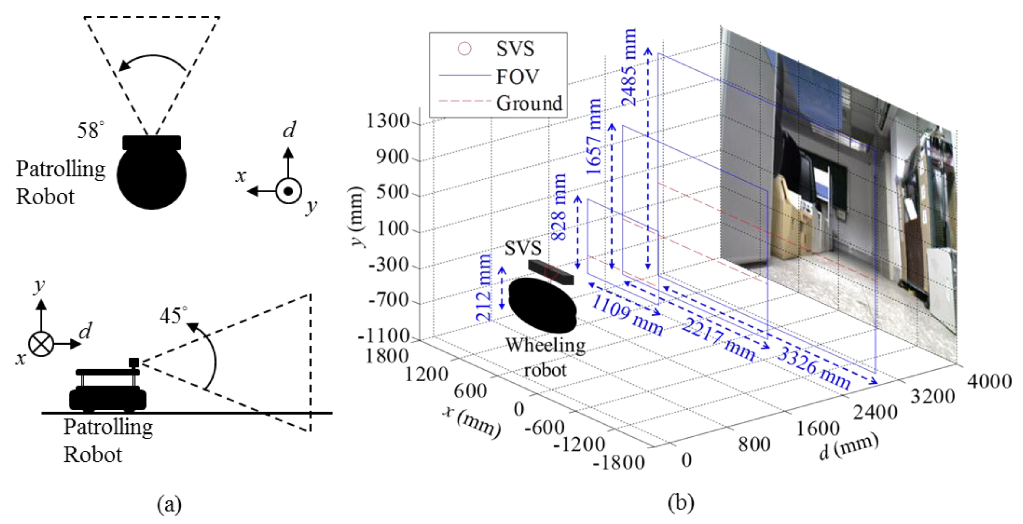
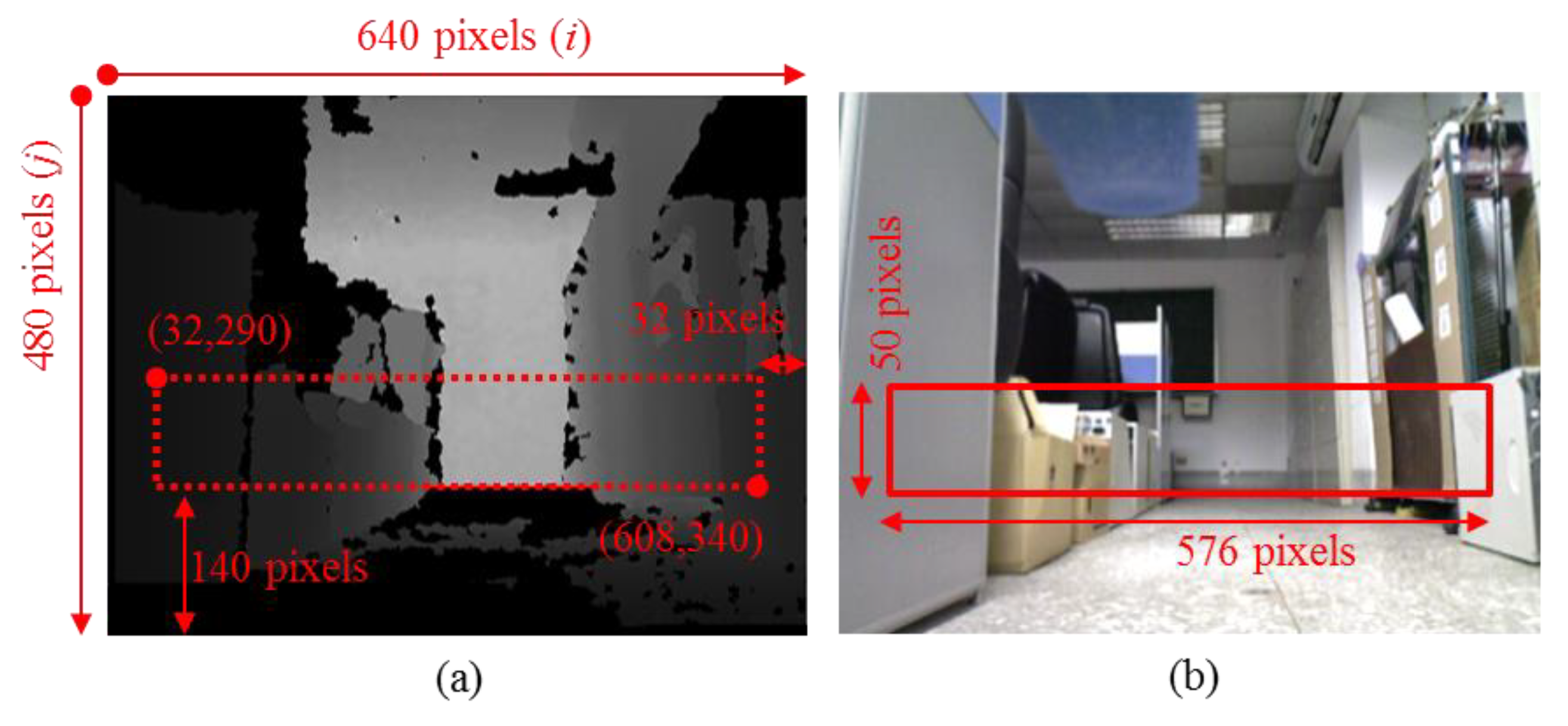
3.1. Imaging Space Conversion and Patrol Path Determination

The proposed SVS is mounted on the robot parallel to the ground and separated by 212 mm. The field of view (FOV) is 45 degrees in the vertical and 58 degrees in the horizontal, respectively, as the plan and side views of the robot depicted in Figure 4a. The height and width of the visible windows are as follows: 1000 mm from SVS (828 mm × 1109 mm), 2000 mm from SVS (1657 mm × 2217 mm), and 3000 mm from SVS (2485 mm × 3326 mm), as shown in Figure 4b. The FOV is resolved to 640 × 480 pixels, and each pixel is described with RGB color space and the world coordinates [ x i , j y i , j d i , j ] , 0 i 640 , 0 j 480 , where x i , j , y i , j , and d i , j are the width, height and depth from the center of SVS, respectively.
In order to make the patrol path random, depth information of the image is analyzed for searching possible patrol paths in this research, instead of using existing path planning. In addition, to reduce the computation required for processing information in the identification of a suitable path, a region of interest (ROI) is defined from the following image coordinates (pixel number): (32,290) to (608,340), as shown in Figure 5a. The ROI is chosen based on the height where the SVS is installed and the width of the robot. Figure 5b presents a corresponding color image with ROI. Assume that i and j are the horizontal and vertical coordinates on the ROI image plane, where 32 i 608 and 290 j 340 . In order to find a possible path region in ROI, the minimum depth at each column of ROI is selected as D ¯ = [ d ¯ 1 d ¯ 2 d ¯ n ] at first. The size thresholds of a path are defined as follows: depth d T (1500 mm) and width w T (3520 mm). In the following, four steps of suitable path identification are described:
  • Initially, compare each d ¯ n in D ¯ with the threshold of depth d T . The d ¯ n which are larger than d T continuously are selected as a sub-section D ¯ k , which D ¯ k D ¯ .
  • Select the largest section D ¯ k of D ¯ , and calculate the corresponding real width w k of the selected section. Assume the selected section D ¯ k = [ d ¯ 1 k d ¯ 2 k d ¯ m k ] , m n , and the width of the corresponding world coordinates are [ x i , j k 1 x i , j k 2 x i , j k m ] , then the width w k of the section D ¯ k can be estimated as follows:
    w k = m 640 ( d ¯ 1 k + d ¯ m k ) π + ( x i , j k m x i , j k 1 ) 2 ,
  • As long as the calculated width w k exceeds width threshold w T , then this route (the region of selected section D ¯ k ) is adopted as a suitable path. The angle θ d from the center of the image plane (the head of the robot) to the center of the path is then calculated to control the rotation of the robot. Assume i c is the center of FOV, and i d is the middle of the selected section D ¯ k on the horizontal axis of image coordinate, then the angle between the head of the robot and the center of the desired path can be calculated as follows:
    θ d = ( i d i c 640 ) · 58 ° .
  • If the analysis results fail to provide a viable path, the robot rotates counterclockwise (CCW) in search of another route.

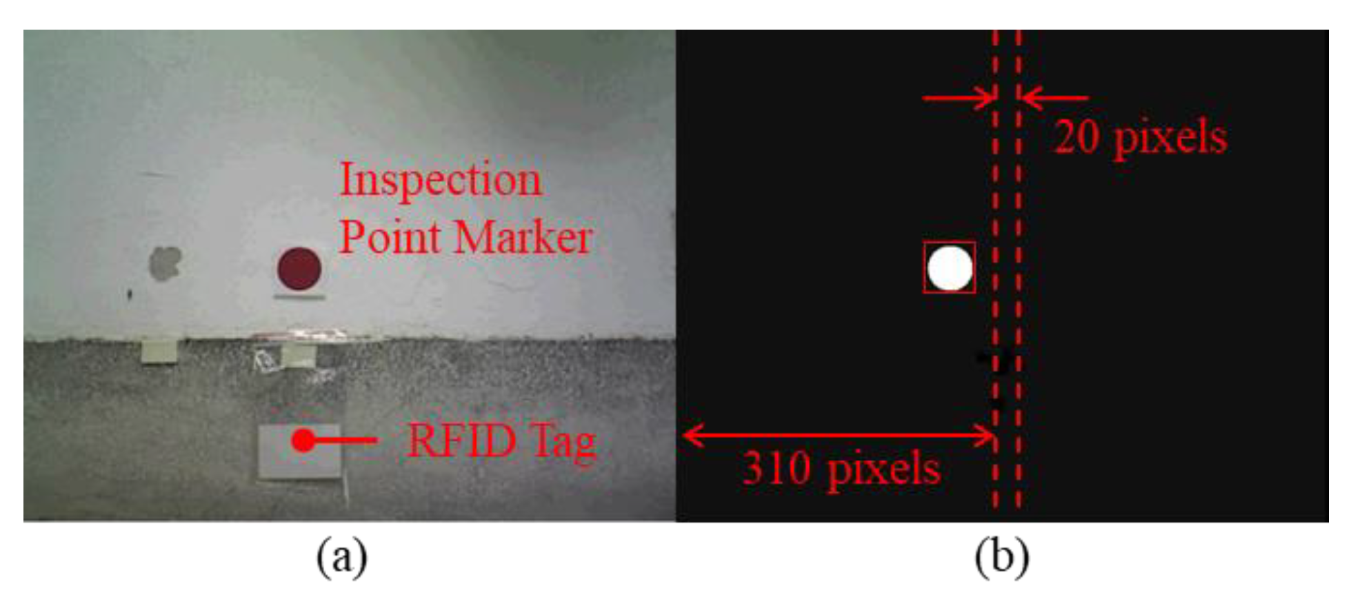
3.2. Signing in at Inspection Points

The patrolling of the robot does not only follow the path which is determined from the depth image, but also guided to the specified location by detecting inspection points. The inspection points are made by a colored marker and an RFID tag. As shown in Figure 6a, the RFID tag as an inspection point is mounted on walls 12 cm above the ground in accordance with the RFID sensor of the robot. This location was marked using a red circular patch (diameter 4.8 cm) at 21 cm above the ground for the SVS system of robot to identify while the robot moving closer to the inspection point. The identification process is divided into two steps, color and shape recognition. In order to prevent the influence of light condition, color images from the SVS is transferred from RGB (red, green, and blue) to HSV (hue, saturation, and value) color space at first. Assume p r , p g , p b are the values in RGB color space per pixel, [ p r p g p b ] [ 0 , 1 ] , and p m a x , p m i n are the maximum and minimum one in [ p r p g p b ] , then the values in HSV color space per pixel can be calculated from:
p h = cos 1 ( 0.5 ( 2 p r p g p b ) ( p r p g ) 2 + ( p r p b ) ( p g p b ) )
p s = { 0 , if   p m a x = 0 1 p m i n p m a x ,   else
p v = p m a x .
The transferred image is then binarized by the threshold which is defined as 0 ° p h 10 ° , 33.3 % p s 56.9 % , and 29.4 % p v 100 % to filter the red color. After the color recognition process, the circle Hough transform (CHT) function of the openCV library is then used for shape recognition. Circles with a radius between 22 to 70 pixels in the binarized images are selected as candidates, and the biggest one is considered as an inspection point, such as depicted in Figure 6b.
While the inspection point is detected, the function of the robot will change from patrolling to signing. Moreover, the algorithm used for signing is designed by controlling the robot to align the center of the detected circle. Assume the image coordinate of the detected circle center in horizontal is i c c , and the edges of the center region are i l T and i r T . If i c c is less than i l T , then the robot is turned CCW for 15 degrees. On the other hand, if i c c is larger than i r T , then the robot is turned clockwise (CW) for 15 degrees. The 15 degrees of turning is limited by the minimum movement of the robot. As long as the value of i c c falls between i l T and i r T , then the robot moves toward the circle marker until the RFID tag is detected. This algorithm is described in (6). Based on experiment results, we set the values of i l T and i r T to 310 and 330, respectively.
{ Turned   CCW   for   15 ° ,   if   i c c < i l T Turned   CW   for   15 ° ,   if   i c c > i r T Go   forward ,   if   i l T i c c i r T ,
When the robot is sufficiently close to the RFID sensor to detect the RFID tag, the tag ID and sign-in time are recorded, and the signing task is deemed to have been completed. Based on the left-hand-rule, the robot then rotates CCW until the circle target is outside the viewing window, whereupon it continues its patrolling task.

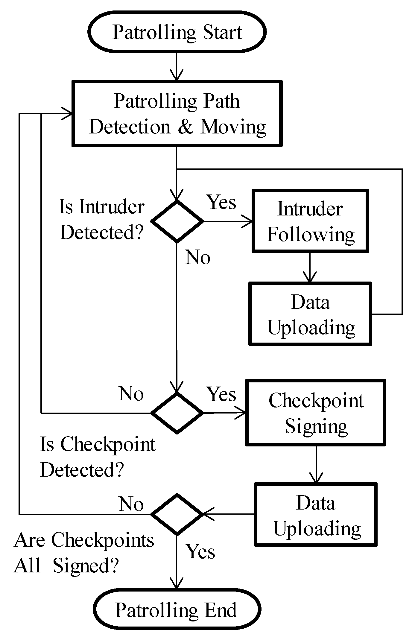
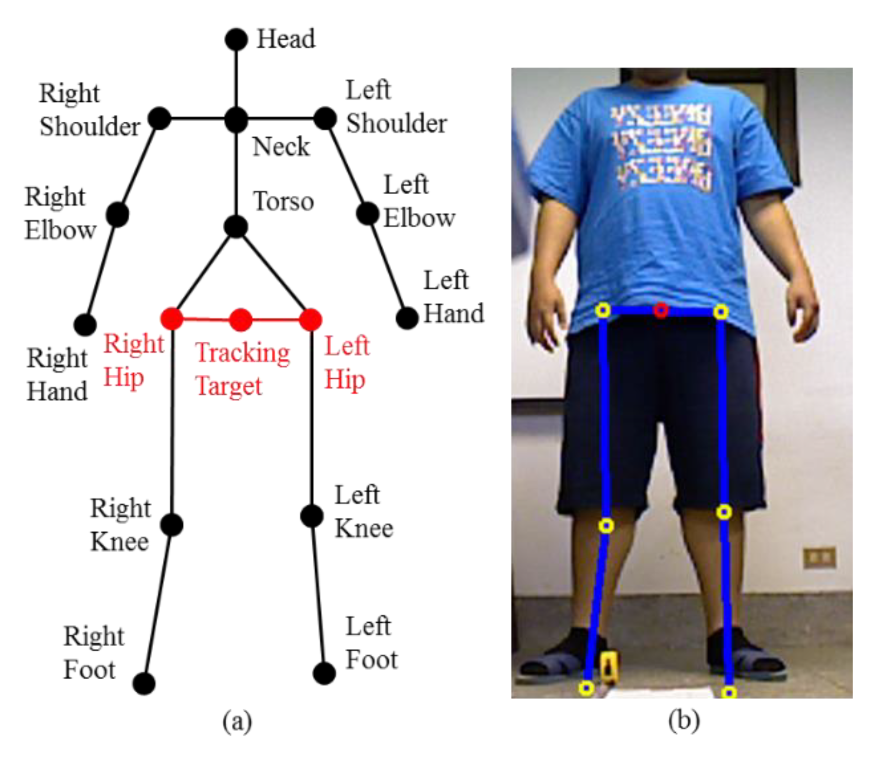
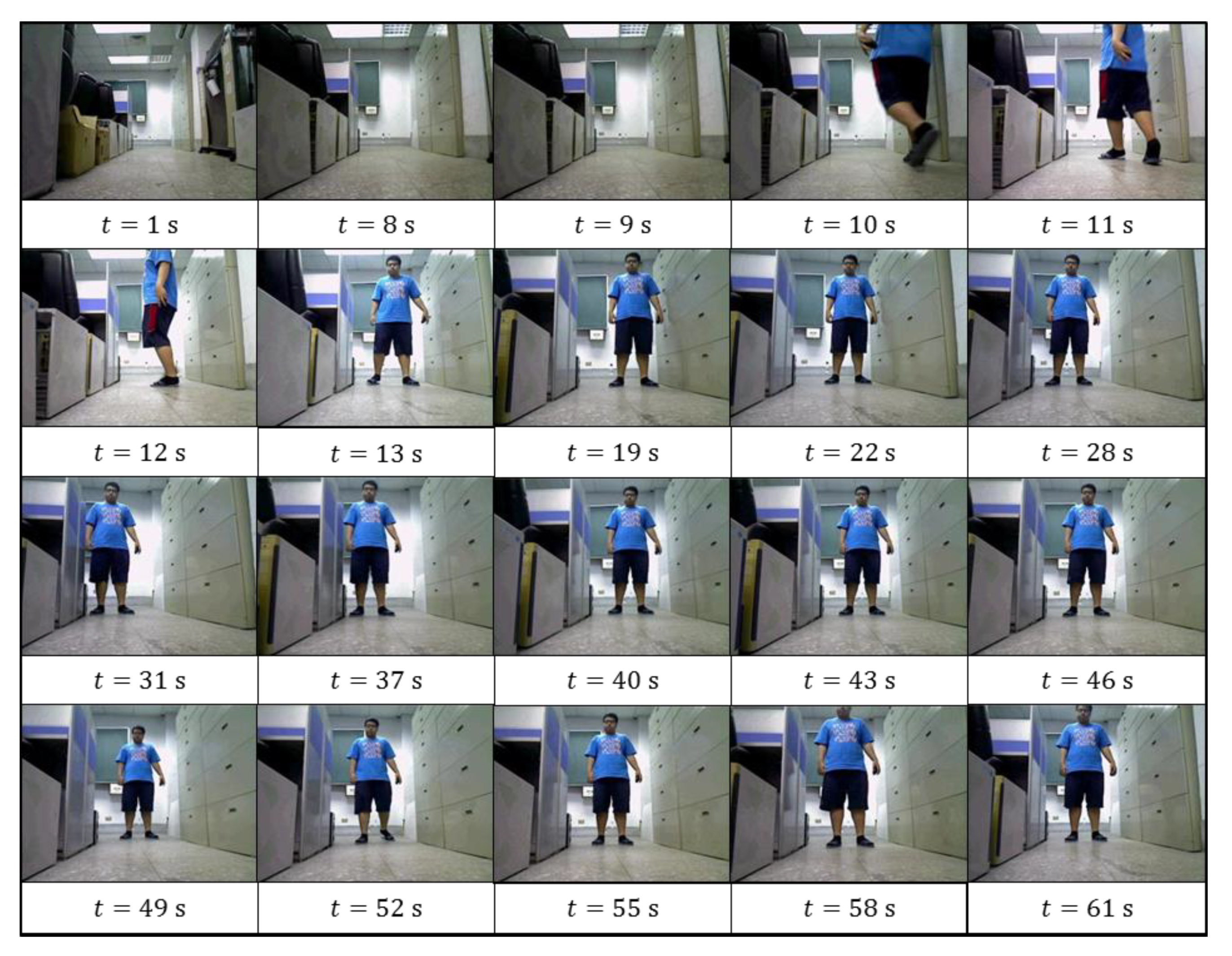
3.3. Detection and Tracking of Intruders

When an intruder appears in the FOV of the SVS, the skeleton of the individual is analyzed to identify its feature. The functions of the openNI library is used for skeleton detection, and the identified feature is composed of joints and limb links, as shown in Figure 7a. Given the height of the intruder is about 170 cm, then the proposed distance between the intruder and the robot (or the SVS) for detection is 2500 mm to 3000 mm. In this range, the full body of the intruder can be viewed in the field of view (FOV) of SVS for skeleton analysis without being too close or too far. In order to track the intruder, the center between left and right hip nodes is used to estimate the orientation and the distance between the robot and the intruder. Assume that the image coordinate in horizontal and depth of the left and right hip nodes are ( i l h i r h ) and ( d l h d r h ) , respectively. Thus, the tracking target of the intruder and its distance are defined as i c h = ( i l h + i r h ) / 2 and d c h = ( d l h + d r h ) / 2 . The detection results are presented in Figure 7b. In addition, while an intruder is detected, the function of the robot is changed from patrolling to tracking until the intruder disappears from the FOV of SVS.
On the other hand, the tracking algorithm is similar to the inspection point approach algorithm, except for the near and far threshold values of tracking length, d k n and d k f . At first, the robot is turned until i l T i h i r T . As long as the value of d c h exceeds the far threshold value of tracking length d k f , then the robot moves forward; i.e., until the value of d c h is less than d k f . Conversely, the robot moves backward until d c h is larger than d k n . If the value of d c h falls between d k n and d k f , then the robot remains in the same position. The code of the tracking algorithm is shown in algorithm 1. Moreover, to view the intruder fully, the values of d k n and d k f are set to 2500 mm and 3000 mm, respectively. The robot also records images of intruders while tracking them, and uploads the images to a server via the upload web-service. When the target moves beyond the viewing window, the robot ceases its tracking task and returns to its patrol task.
Algorithm 1 Tracking of intruders.
1:Detecting the skeleton of an intruder
2:Getting the image coordinates and distance of the left and right hip, ( i l h i r h ) and ( d l h d r h )
3:Calculating the tracking target, i c h = ( i l h + i r h ) / 2 , and d c h = ( d l h + d r h ) / 2
4:if i c h < i l T then
5:     The robot is turned CCW for 15 °
6:else if i c h > i r T then
7:     The robot is turned CW for 15 °
8:else if i l T i c h i r T then
9:     If d c h > d k f then
10:          The robot moves forward
11:     else if d c h < d k n then
12:          The robot moves backward
13:     else if d k n d c h d k f then
14:          The robot remains in the same position
15:     end if
16: end if

3.4. Wireless Backup and Query Service

Three web-service functions (upload, history and real-time information service) were installed on the server for the remote backup of monitoring data and the submission of queries. The upload service is used for the transmission of data from the robot to the server, whereas the other two services enable remote users to submit queries pertaining to historical or real-time monitoring data held on the server. The robot backs up information when signing in at inspection points and when an intruder is detected. The processor first connects to a wireless access point using a Wi-Fi module. The human–machine interface (HMI) contacts the upload web service to transmit the tag number and sign-in time to the server. After receiving the data, the server records the information within a table in the SQL database. When an image of an intruder is captured by the robot, the image data is encoded to base64 format and then transmitted (along with the time of detection) to the upload service. The base 64 data is then decoded back into an image by the server, whereupon it is saved in PNG format within a specific folder. The image file is named using the time of detection to facilitate subsequent queries. A client program was also developed to assist in data queries. This program provides real-time monitoring data as well as historical data by accessing the real-time information service or history service, respectively. The real-time information service searches for the latest data within the database, whereas the history service searches for data pertaining to the specific period of time defined by the user. The architecture of the data remote backup and querying system is presented in Figure 8.

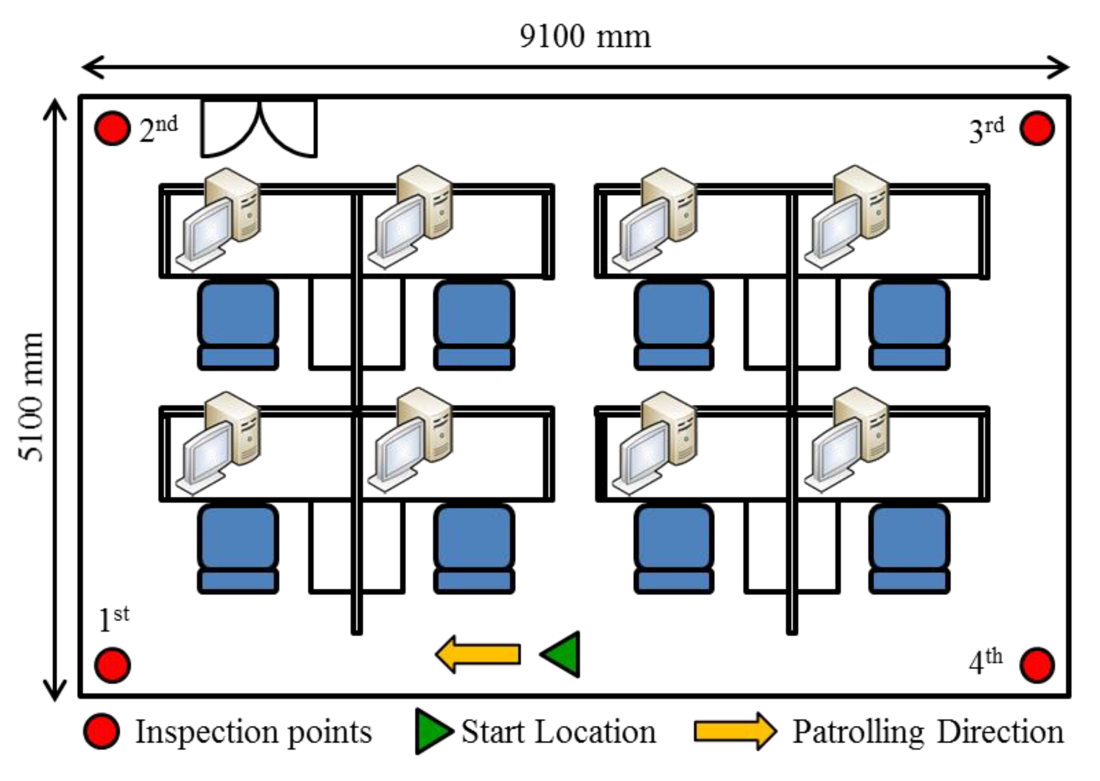
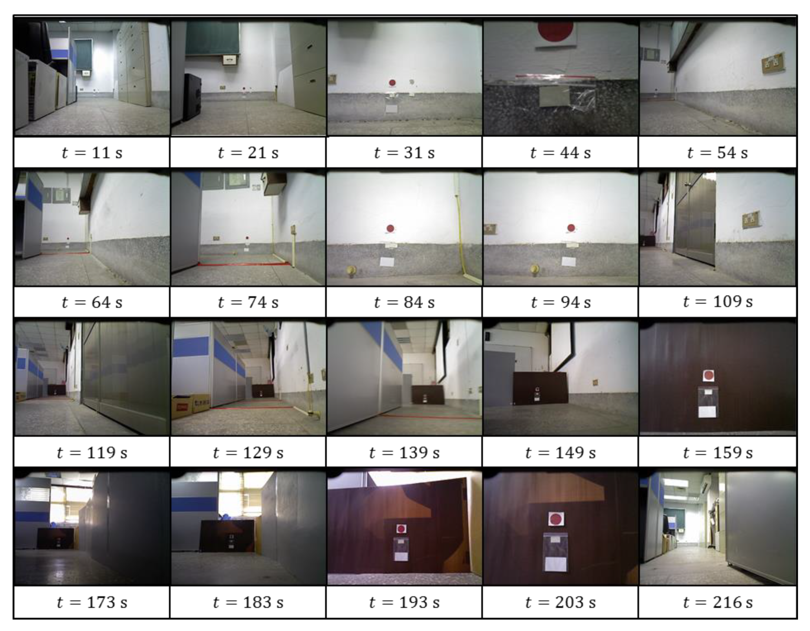
4. Experiment and Results

An environment based on the proposed functions was created to verify the efficacy of the proposed algorithm. The environment was a 9100 mm x 5100 mm square space with several pieces of office furniture located in the center, and inspection points were set in each corner of the room, as shown in Figure 9. At the beginning of the experiment, the robot was placed along a wall. Patrolling began when a user pressed the start button on the robot’s HMI. The sequence of the patrol task is outlined in the following.
  • From the start point until 21 s, the robot searched for a passable path and followed the resulting path.
  • At 31 s, the 1st inspection point marker was detected by the robot, to which the robot approached.
  • At 44 s, the robot reached the 1st inspection point. The RFID tag number was recorded by the robot, thereby completing the 1st inspection point sign-in.
  • From 44 s to 54 s, the robot rotated CCW in search of its next route to follow.
  • From 54 s to 74 s, the robot moved from the 1st to the 2nd inspection point.
  • At 84 s, the robot located the 2nd inspection point. The center of the marker image was not located in the target region of the image plane (between 310 and 330 pixels); therefore, the robot rotated until the image marker was near the center of the image plane (at 94 s), as shown in the figure.
  • At 94 s, the robot proceeded forward to sign-in at this inspection point at 101 s, whereupon it rotated and began patrolling from the 2nd inspection point to the 3rd inspection point (109 s to the 139 s).
  • The 3rd and 4th inspection points were identified at 159 s and the 203 s, respectively. After checking-in at the final (4th) inspection point, the robot continued patrolling for approximately 30 seconds before halting.
A color image and the corresponding depth information from the SVS of the above procedure are recorded throughout the experiment, as shown in Figure 10 and Figure 11, and Video S1 (Supplementary Materials).
The depth information D ¯ of the ROI was also recorded to analyze the trajectory of the robot while on patrol. In order to fix the distortion caused by size-changing of FOV in different distance from SVS, the recorded data is transformed by Equation (2) and presented in the form of polar space, as shown in Figure 12. The FOV is depicted with a blue dashed line, and the threshold of depth d T is shown with a red dashed line. In addition, the color scale is used to present the values of each d ¯ n in D ¯ . The analysis results are listed in the following:
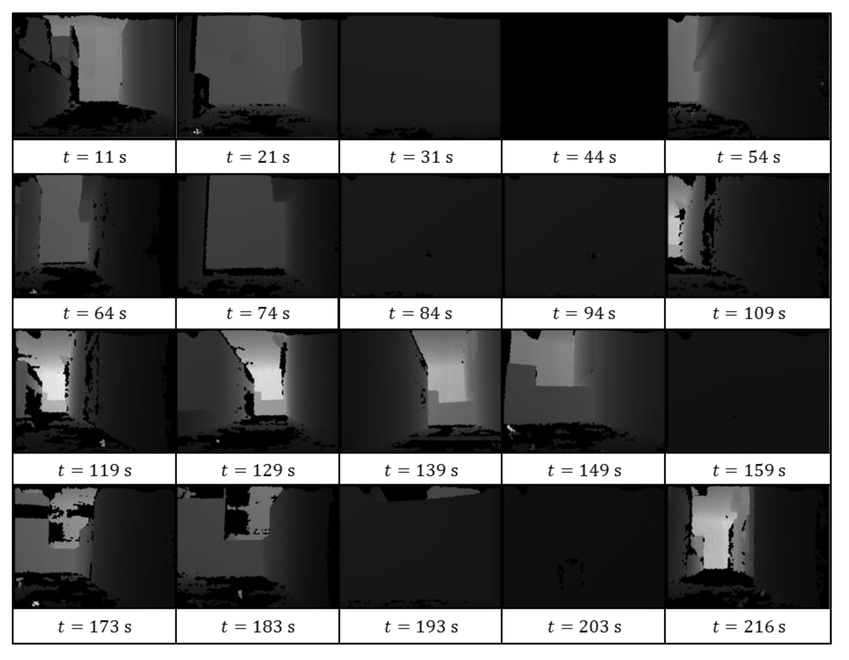
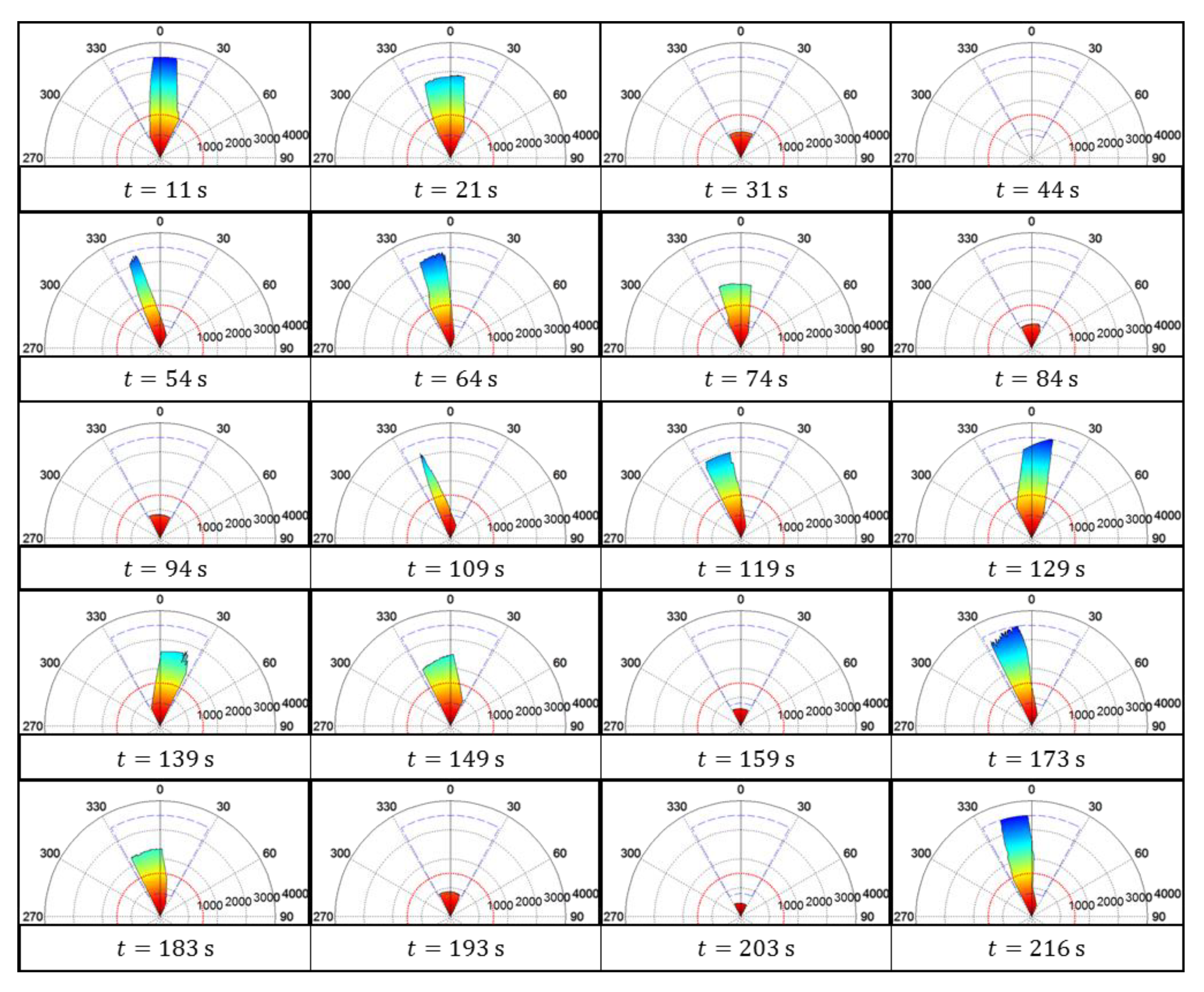
  • At 11 s and 129 s, the center of the section D ¯ k was near the origin of the polar space, which means that the robot was moving toward the center of the patrol path.
  • Between 21 s and 31 s, the robot was approaching the 1st inspection point, as indicated by the decrease in recorded depth.
  • While the robot was signing in at the 1st inspection point (at 44 s), the distance between the wall and the robot was less than the minimum distance required by the SVS for detection. Thus, no depth information appears in the polar space during this time. Similarly, the depth values disappeared at 94 s, 159 s, and 203 s, corresponding to the sign-in process at the 2nd, 3rd, and 4th inspection points.
  • After signing in, the robot rotated CCW to search for a suitable path, whereupon the depth values increased considerably from the left side to the right side from 44 s to 64 s. This is similar to the records from 94 s to 119 s, 159 s to 173 s, and 193 s to 216 s.
As shown in Figure 13, the robot followed the proposed algorithm in identifying patrol paths and signing in at inspection points.
There were eight experiments made for patrolling; four of them were patrolling with inspection points placed, and the others did not. The robot started patrolling from the same location in each experiment. The patrol time comparison of each experiment is shown in Table 1. The average time of patrolling with/without inspection points was about 206/205.75 sec, respectively. Though the average time of patrolling with the inspection point was larger than the other one, however, the minimum elapsed time of the former can be reduced to only 194 sec. On the other hand, the maximum elapsed time of the latter was 260 sec, which was larger than any elapsed time of the experiment with inspection points placed. This is because the proposed system runs the sing-in procedure while inspection points are placed in the patrol environment, and the sing-in process took about 5 to 8 sec per inspection point. In addition, without placing inspection points, the robot can only used the first method and the built-in obstacle avoidance function to find the patrol path. While the robot was moving to corners of a room and could not find a way out, this caused time-wasting for backing to patrolling.
Several other experiments were conducted to verify the efficacy of the intruder detection function. Figure 13 presents recorded images of the intruder in one of the experiments. While the robot was executing its patrol task, an intruder suddenly ran into the FOV of the SVS (at 10 s), whereupon the SVS detected the skeleton of the intruder (at 13 s). The robot simultaneously ceased its patrol task and initiated the intruder tracking task. From 19 s to 43 s, the intruder was pacing around, during which time the robot rotated to keep the intruder within the center region of the image plane. As the intruder was walking backward (from 43 s to 49 s), the robot followed in order to maintain the depth value of tracking target d h between the near-threshold value d k n and far threshold value d k f . In this experiment, the robot proved highly effective in using the proposed algorithm to detect, identify, and track the intruder. Finally, the recorded images can be queried from a database by the graphic user interface (GUI) built in the user client.

5. Conclusions

This paper outlines the architecture of a novel robot designed to patrol in the workspace. The robot has four functions: independent patrolling, signing in at inspection points, the detection and tracking of intruders, and remote backup of data to facilitate real-time monitoring and user queries. The robot receives from an SVS depth information pertaining to the environment for use in the identification of a suitable path to follow. Inspection point markers encountered along this path cause the robot to veer off the path to check-in. Upon arrival at the inspection point, the number of the RFID tag at that point is recorded. After signing in, the robot rotates CCW and continues its patrol task. In the event that an intruder appears within the FOV of the SVS, the skeleton of the intruder is identified according to the function of the openNI library. The intruder is subsequently tracked and imaged until the intruder moves beyond the viewing window. All data recorded during this encounter is uploaded to the server, to enable monitoring in real-time and facilitate subsequent queries of historical data. Several experiments verify the efficacy of the proposed algorithm.
For comparison to other guard solutions, e.g., security cameras, as mentioned in the introduction, sweeping robots have gradually become commonplace in every home or workspace environment. If there is a simple and low-cost method that can increase the patrol function on traditional sweeping robots, it will effectively solve the problem of home security. In addition, the prices of the retrofit devices (SVS and RFID sensors, etc.) on sweeping robots of the proposed system are lower than N.T.D. 5000, but the prices of a security camera is generally higher than that.
Secondary, mobility and randomness are the two key points of the patrol system. For the proposed system, there are two functions can achieve these objectives, one is path-free autonomous patrol, and the other is intruder following. The path-free autonomous patrol function creates a random patrol path which can avoid intruders to find possible flaws for planned paths in advance, and the intruder following function can avoid blind spots caused by furniture, and then record more image information of intruders. On the other hand, a security camera is usually installed at a fixed location, and its rotation degree is limited. Therefore, more cameras need to be installed to cover all monitoring ranges, and lack of mobility.
Moreover, information security and privacy are issues that everyone values in recent years. For the proposed system, the user cannot get the image information directly from the patrol robot. The recorded images are saved in a server at first. Users need to login the server to get access to watch the records. Generally, a server has a higher level of information security protection. On the other hand, a security camera has a convenience that users can monitor remotely and directly. However, now a day, “security camera has been hijacked or hacked” is heard from time to time, and these events will cause users to concern about the security of the patrol by security camera.
Summarily, the proposed system is not convenient for users to view patrol results, however, it has a lower price, better path randomness, better mobility, and more information security and privacy. The comparison results are shown in Table 2.

Supplementary Materials

The following are available online at https://www.mdpi.com/2076-3417/10/3/974/s1, Video S1: The recorded color images and the depth information from the SVS during the patrol task.

Author Contributions

Developed the idea of the proposed method and directed the experiments, C.-W.L.; fabricated the devices and performed the experiments, C.-Y.C. All authors have read and agreed to the published version of the manuscript.

Funding

This research was funded by the Ministry of Science and Technology of Taiwan, R.O.C. with Grant number MOST-108-2221-E-606-015.

Acknowledgments

The authors thank the financial support from the Ministry of Science and Technology of Taiwan, R.O.C. with Grant number. MOST-108-2221-E-606-015.

Conflicts of Interest

The authors declare no conflict of interest.

Nomenclature

x i , j Distance from the center of SVS on the x-axis (width) at pixel ( i , j )
y i , j Distance from the center of SVS on the y-axis (height) at pixel ( i , j )
d i , j Distance from the center of SVS on the z-axis (depth) at pixel ( i , j )
d T Threshold of depth used to determine a possible path.
d ¯ n Minimum depth at n-th column of ROI.
D ¯ set of d ¯ n
D ¯ k kth set of d ¯ n which are larger than d T continuously, D ¯ k D ¯
d ¯ m k mth element of D ¯ k
w T Threshold of width used to determine a possible path.
w k Width at the range of a selected D ¯ k in the real world.
i c The center of FOV on the horizontal axis of the image coordinate
i d The middle of the selected section D ¯ k on the horizontal axis of image coordinate
i c c The detected circle center on the horizontal axis of image coordinate
i l T Left edge of the center region on the horizontal axis of image coordinate
i r T Right edge of the center region on the horizontal axis of image coordinate
i l h Left hip node on the horizontal axis of image coordinate
i r h Right hip node on the horizontal axis of image coordinate
d l h Depth of the left hip node
d r h Depth of the right hip node
i c h The center between the left and right hip node on the horizontal axis of image coordinate
d c h The distance from the center between the left and right hip node to the SVS
d k n Near threshold values of tracking length
d k f Far threshold values of tracking length

References

  1. Lee, C.W.; Lee, J.D.; Ahn, J.; Oh, H.J.; Park, J.K.; Jeon, H.S. A Low Overhead Mapping Scheme for Exploration and Representation in the Unknown Area. Appl. Sci. 2019, 9, 3089. [Google Scholar] [CrossRef] [Green Version]
  2. Dwijotomo, A.; Abdul Rahman, M.A.; Mohammed Ariff, M.H.; Zamzuri, H.; Wan Azree, W.M.H. Cartographer SLAM Method for Optimization with an Adaptive Multi-Distance Scan Scheduler. Appl. Sci. 2020, 10, 347. [Google Scholar] [CrossRef] [Green Version]
  3. Li, X.; Wang, D.; Ao, H.; Belaroussi, R.; Gruyer, D. Fast 3D Semantic Mapping in Road Scenes. Appl. Sci. 2019, 9, 631. [Google Scholar] [CrossRef] [Green Version]
  4. Lee, T.J.; Kim, C.H.; Cho, D.I.D. A Monocular Vision Sensor-Based Efficient SLAM Method for Indoor Service Robots. IEEE Trans. Ind. Electron. 2019, 66, 318–328. [Google Scholar] [CrossRef]
  5. Valiente, D.; Gil, A.; Payá, L.; Sebastián, J.M.; Reinoso, Ó. Robust Visual Localization with Dynamic Uncertainty Management in Omnidirectional SLAM. Appl. Sci. 2017, 7, 1294. [Google Scholar] [CrossRef] [Green Version]
  6. Muñoz-Bañón, M.Á.; del Pino, I.; Candelas, F.A.; Torres, F. Framework for Fast Experimental Testing of Autonomous Navigation Algorithms. Appl. Sci. 2019, 9, 1997. [Google Scholar] [CrossRef] [Green Version]
  7. Li, I.H.; Wang, W.Y.; Chien, Y.; Fang, N.H. Autonomous Ramp Detection and Climbing Systems for Tracked Robot Using Kinect Sensor. Int. J. Fuzzy Syst. 2013, 15, 452–459. [Google Scholar]
  8. Li, I.H.; Hsu, C.C.; Lin, S.S. Map Building of Unknown Environment Based on Fuzzy Sensor Fusion of Ultrasonic Ranging Data. Int. J. Fuzzy Syst. 2014, 16, 368–377. [Google Scholar]
  9. Cherubini, A.; Spindler, F.; Chaumette, F. Autonomous Visual Navigation and Laser-Based Moving Obstacle Avoidance. IEEE Trans. Intell. Transp. Syst. 2014, 15, 2101–2110. [Google Scholar] [CrossRef]
  10. Jiang, G.; Yin, L.; Jin, S.; Tian, C.; Ma, X.; Ou, Y. A Simultaneous Localization and Mapping (SLAM) Framework for 2.5D Map Building Based on Low-Cost LiDAR and Vision Fusion. Appl. Sci. 2019, 9, 2105. [Google Scholar] [CrossRef] [Green Version]
  11. Kang, X.; Li, J.; Fan, X.; Wan, W. Real-Time RGB-D Simultaneous Localization and Mapping Guided by Terrestrial LiDAR Point Cloud for Indoor 3-D Reconstruction and Camera Pose Estimation. Appl. Sci. 2019, 9, 3264. [Google Scholar] [CrossRef] [Green Version]
  12. Zou, R.; Ge, X.; Wang, G. Applications of RGB-D Data for 3D Reconstruction in the Indoor Environment. In Proceedings of the 2016 IEEE Chinese Guidance, Navigation and Control Conference (CGNCC), Nanjing, China, 12–14 August 2016; pp. 375–378. [Google Scholar]
  13. Ramer, C.; Sessner, J.; Scholz, M.; Zhang, X.; Franke, J. Fusing Low-Cost Sensor Data for Localization and Mapping of Automated Guided Vehicle Fleets in Indoor Applications. In Proceedings of the 2015 IEEE International Conference on Multisensor Fusion and Integration for Intelligent Systems (MFI), San Diego, CA, USA, 14–16 September 2015; pp. 65–70. [Google Scholar]
  14. Jiang, G.; Yin, L.; Liu, G.; Xi, W.; Ou, Y. FFT-Based Scan-Matching for SLAM Applications with Low-Cost Laser Range Finders. Appl. Sci. 2019, 9, 41. [Google Scholar] [CrossRef] [Green Version]
  15. Li, S.; Handa, A.; Zhang, Y.; Calway, A. HDRFusion: HDR SLAM Using a Low-Cost Auto-Exposure RGB-D Sensor. In Proceedings of the 2016 Fourth International Conference on 3D Vision (3DV), Stanford, CA, USA, 25–28 October 2016; pp. 314–322. [Google Scholar]
  16. Bergeon, Y.; Hadda, I.; Křivánek, V.; Motsch, J.; Štefek, A. Low Cost 3D Mapping for Indoor Navigation. In Proceedings of the International Conference on Military Technologies (ICMT) 2015, Brno, Czech Republic, 19–21 May 2015. [Google Scholar]
  17. Calloway, T.; Megherbi, D.B. Using 6 DOF Vision-Inertial Tracking to Evaluate and Improve Low Cost Depth Sensor based SLAM. In Proceedings of the 2016 IEEE International Conference on Computational Intelligence and Virtual Environments for Measurement Systems and Applications (CIVEMSA), Budapest, Hungary, 27–28 June 2016. [Google Scholar]
  18. Gong, Z.; Li, J.; Li, W. A Low Cost Indoor Mapping Robot Based on TinySLAM Algorithm. In Proceedings of the 2016 IEEE International Geoscience and Remote Sensing Symposium (IGARSS), Beijing, China, 10–15 July 2016; pp. 4549–4552. [Google Scholar]
  19. Anandharaman, S.; Sudhakaran, M.; Seyezhai, R. A Low-Cost Visual Navigation and Mapping System for Unmanned Aerial Vehicle Using LSD-SLAM Algorithm. In Proceedings of the 2016 Online International Conference on Green Engineering and Technologies (IC-GET), Coimbatore, India, 19 November 2016; p. 16864750. [Google Scholar]
  20. Xi, W.; Ou, Y.; Peng, J.; Yu, G. A New Method for Indoor Low-Cost Mobile Robot SLAM. In Proceedings of the 2017 IEEE International Conference on Information and Automation (ICIA), Macau, China, 18–20 July 2017; pp. 1012–1017. [Google Scholar]
  21. Fang, Z.; Zhao, S.; Wen, S. A Real-Time and Low-Cost 3D SLAM System Based on a Continuously Rotating 2D Laser Scanner. In Proceedings of the 2017 IEEE 7th Annual International Conference on CYBER Technology in Automation, Control, and Intelligent Systems (CYBER), Honolulu, HI, USA, 31 July–4 August 2017; pp. 4544–4559. [Google Scholar]
  22. Bae, H.; Oh, J.; Lee, K.K.; Oh, J.H. Low-Cost Indoor Positioning System using BLE (Bluetooth Low Energy) based Sensor Fusion with Constrained Extended Kalman Filter. In Proceedings of the 2016 IEEE International Conference on Robotics and Biomimetics (ROBIO), Qingdao, China, 3–7 December 2016; pp. 939–945. [Google Scholar]
  23. DiGiampaolo, E.; Martinelli, F. A Robotic System for Localization of Passive UHF-RFID Tagged Objects on Shelves. IEEE Sens. J. 2018, 18, 8558–8568. [Google Scholar] [CrossRef]
  24. Chen, K.C.; Tsai, W.H. Vision-based autonomous vehicle guidance for indoor security patrolling by a sift-based vehicle-localization technique. IEEE Trans. Veh. Technol. 2010, 59, 3261–3271. [Google Scholar] [CrossRef]
  25. Song, D.; Kim, C.Y.; Yi, J. Simultaneous localization of multiple unknown and transient radio sources using a mobile robot. IEEE Trans. Robot. 2012, 28, 668–680. [Google Scholar] [CrossRef]
  26. Chen, X.; Sun, H.; Zhang, H. A New Method of Simultaneous Localization and Mapping for Mobile Robots Using Acoustic Landmarks. Appl. Sci. 2019, 9, 1352. [Google Scholar] [CrossRef] [Green Version]
  27. Wang, Z.; Chen, Y.; Mei, Y.; Yang, K.; Cai, B. IMU-Assisted 2D SLAM Method for Low-Texture and Dynamic Environments. Appl. Sci. 2018, 8, 2534. [Google Scholar] [CrossRef] [Green Version]
  28. An, V.; Qu, Z.; Roberts, R. A Rainbow Coverage Path Planning for a Patrolling Mobile Robot with Circular Sensing Range. IEEE Trans. Syst. Man Cybern. Syst. 2018, 48, 1238–1254. [Google Scholar] [CrossRef]
  29. Huang, W.Q.; Chang, D.; Wang, S.Y.; Xiang, J. An Efficient Visualization Method of RFID Indoor Positioning Data. In Proceedings of the 2014 2nd International Conference on Systems and Informatics (ICSAI), Shanghai, China, 15–17 November 2014; p. 14852364. [Google Scholar]
  30. Yu, W.S.; Wen, Y.J.; Tsai, C.H.; Ren, G.P.; Lin, P.C. Human following on a mobile robot by low-cost infrared sensors. J. Chin. Soc. Mech. Eng. 2014, 35, 429–441. [Google Scholar]
  31. Hung, M.H.; Chen, K.Y.; Lin, S.S. A web-services-based remote monitoring and control system architecture with the capability of protecting appliance safety. J. Chung Cheng Inst. Technol. 2005, 34, 3854. [Google Scholar]
  32. Lian, F.L.; Lin, Y.C.; Kuo, C.T.; Jean, J.H. Rate and quality control with embedded coding for mobile robot with visual patrol. IEEE Syst. J. 2012, 6, 368–377. [Google Scholar] [CrossRef]
Figure 1. System architecture of autonomous patrolling robot.
Applsci 10 00974 g001
Figure 2. Proposed patrol robot.
Applsci 10 00974 g002
Figure 3. Flowchart showing the process of autonomously patrolling a site.
Applsci 10 00974 g003
Figure 4. (a) The plan and side views and (b) the field of view (FOV) of stereo vision system (SVS) at various distances of the robot.
Applsci 10 00974 g004
Figure 5. The region of interest (ROI) of (a) depth information and (b) color image of the SVS.
Applsci 10 00974 g005
Figure 6. (a) An inspection point marker with radio frequency identification (RFID) tag and (b) the corresponding binarized results from SVS.
Applsci 10 00974 g006
Figure 7. (a) Feature points of skeleton; (b) intruder detection results.
Applsci 10 00974 g007
Figure 8. Architecture of remote data backup and querying system.
Applsci 10 00974 g008
Figure 9. Environment used in patrol experiment.
Applsci 10 00974 g009
Figure 10. Color image recorded by SVS during the patrol task.
Applsci 10 00974 g010
Figure 11. Depth information recorded from SVS during the patrol task.
Applsci 10 00974 g011
Figure 12. Depth information recorded in the form of polar space.
Applsci 10 00974 g012
Figure 13. The recorded images of intruder recorded by robot.
Applsci 10 00974 g013
Table 1. The patrol time comparison of each experiment.
Inspection Points PlacedStarting Time
(hh:mm:ss)
Stopping Time
(hh:mm:ss)
Elapsed
Time (s)
Average
Time (s)
Yes10:53:5510:57:17202206
15:22:0215:25:48226
17:40:3317:43:55202
18:11:1918:14:33194
No13:41:5713:44:40163205.75
16:38:2416:41:56212
16:54:0416:57:12188
09:24:4309:29:03260
Table 2. The comparison between the proposed system and other solutions.
Proposed SystemOther Solutions
(e.g., Security Camera)
PriceVX
Path RandomnessVX
MobilityVX
ConvenientXV
Security and PrivacyVX

