Article

Experimental Assessment of the Effects of Low-Emissivity Paints as Interior Radiation Control Coatings

TEBE research group, Department of Energy, Politecnico di Torino, 10129 Torino, Italy
*
Author to whom correspondence should be addressed.
Appl. Sci. 2020, 10(3), 842; https://doi.org/10.3390/app10030842
Submission received: 24 December 2019 / Revised: 11 January 2020 / Accepted: 19 January 2020 / Published: 24 January 2020

Abstract

:
Radiation Control Coatings (RCC) are commonly recognised as paints, in which the long-wave radiation emissivity can be dramatically reduced from 0.9 to below 0.25 due to the dispersion of aluminium flakes inside the base paint. The low emissivity (Low-E) feature makes these materials particularly suitable for reducing the radiative heat exchange in building components and worthy of being used in roof attics, pipes, heat storage tank, etc. However, in the last few years, the application to the indoor surfaces of the building envelope has become quite popular, because the reflective properties can be exploited to increase the thermal comfort and reduce the winter heat losses. Except for aluminium based paint, that, for their strong metallized effect, suffer from some aesthetical limitation, the claimed performance of most of the other commercially available reflective paints are not universally recognized and in most of the cases their properties are misled, referring to visible and short wave infrared reflectivity. In this paper, a new methodology for assessing the long-wave thermal emissivity by using a heat flow meter apparatus is proposed. Moreover, the thermal emissivity of different paint mixtures with reduced metallised effect is assessed. The results allow for affirming that paints with acceptable aesthetic value (limited metallized effect) can reach an emissivity of ~0.60 instead of a typical emissivity of paint between 0.85–0.90. Furthermore, the partition wall of a double climatic chamber apparatus was painted with different low-E paints to evaluate whether an increase of the indoor operative temperature would have been observed. A slight, but not negligible, increase was shown of up to 0.3 °C and 0.6 °C for paint with an emissivity of ~0.6 and ~0.4, respectively.

1. Introduction

The effect of reflective thermal insulation was discovered in the middle of the 19th century by J.C.E. Peclet [1]. He experimentally observed that a multilayer structure of thin metal foil facing airspaces presents good insulation properties. Nevertheless, the commercial development of this technology started in the early 1900s with the patents that were published by E. Schmidt [2] and E. Dykerhoff [3].
Thermal radiation is emitted by all the surfaces at T > 0 K, the radiative power is reciprocally exchanged between bodies at different temperatures. “The term ‘thermal’ includes all of the electromagnetic waves with a wavelength between 10−2 and 103 μm: ultraviolet (UV), light (L) and infrared (IR), wavelength” [4].
However, in opaque building components not exposed to solar radiation, the radiative heat transfer discussed in this paper only includes the IR-radiation (wavelength between 0.76 and 103 μm). The radiative energy is transported by electromagnetic waves that do not need a medium to be transferred (in contrast with conduction and convection heat transfer).
“The radiation that is emitted by a surface, and the rate at which energy is released per unit area (W/m2) is termed the surface emissive power E. In grey bodies (real surface) it is calculated by Equation (1). Where: ε is a radiative property of the surface termed the global emissivity.
This property provides a measure of how efficiently a surface emits energy relative to a blackbody. It strongly depends on the surface material and finishing” [5].
E = ε σ T s 4
The term σ and Ts are, respectively, the Stefan–Boltzmann’s constant = 5.67 × 10⁻⁸ W/(m2 K4), and the surface temperature (K).
The basic principle of Low-E materials is to reduce the emissive IR-radiation power (Low emittance) or reflect most of it in the case of received IR radiative power (high reflectance).
Most of the typical building materials show high IR-emissivity > 0.8 and low IR-reflectivity < 0.2, on the contrary, “Aluminum foil and metallized surface has a very low emittance, which explains its use in reflective insulation and radiant barriers” [6].
In reflective paints identified as Radiation Control Coatings RCC [6], the emissivity can be dramatically reduced from 0.9 to below 0.25. This is possible due to the dispersion of aluminium flakes as pigment inside the base paint coat [6].
Despite the emissivity values of conventional paints being between 0.85 and 0.9, it is possible to find on the market Low-E paints with emissivity that range between 0.15–0.49 [7] (higher if compared to aluminium foil).
This solution can have an advantage, since it could be applied in a faster way (spray paint, brush paint) and can be suitable for a large set of applications in the construction sector by painting: “the inside of a boiler room to reduce the heat losses, the external roof surface to repel summer heat and lower radiation losses in the winter” [6]. Some other examples are provided by [8], in which low emittance paints were applied in the wall behind heaters/radiators to reduce the wall heat losses or by covering the void surfaces in hollow bricks (also analysed in [9,10,11]).
Sedlbauer et al. (2011) studied an interesting application on the exterior surface of ETICS to reducing the Risk of Microbial Growth [12].
Despite the growing interest in this paint technology, nowadays it mainly found its application in reducing the overheating in attic space in cooling dominant climates (Figure 1), as investigated in [13].
Nevertheless, only a limited number of studies, some of them only theoretical, were focused on analysing the possible application of Low-E paints as interior radiation control coatings system (IRCCS) to reduce the building energy consumption for heating and cooling.
An experimental study by Joudi et al. [14,15] analysed the effect of an interior low emissivity coating (ε = 0.25) that was applied to the indoor surface of a small cabin in Sweden. The indoor temperature and the energy consumption for heating and cooling the building was monitored and then compared to a normal cabin without an interior surface coating. The results show a ~5% reduction in heating energy consumption. Moreover, a theoretical study was carried out simulating the energy consumption of a retail house under different climates. The results highlight that reducing the internal surface emissivity determines a significant reduction in the heating energy demand for all of the considered climates. On the contrary, a slight increase of the cooling energy demand was observed. These penalties can be considered negligible in cold climates, on the contrary in a warm climate the increase of the cooling demand in summer cannot be counterbalanced by the winter benefits.
An energy-saving coherent with [15] was reported by Buckmaster et al. [16]. The study analyses through CFD simulations the interaction between the interior emissivity and the energy consumption in a simple room. The results for well-sealed room claims a ~5% of energy saving. Nevertheless, the benefits can significantly differ for high ventilation rate.
More recent theoretical studies of low-emissivity coatings (ε = 0.1) applied to the indoor surfaces of a room, highlight possible savings of up to 22% if an operative temperature-based control at a position near a low-emissivity surface is implemented.
Nevertheless, by using paints with ideal emissivity of 0.1 [15,16,17]), most of the low-emissivity paints commercially available present a higher thermal emissivity [7], even though several studies have theoretically demonstrated interesting improvement in the winter indoor comfort conditions and energy savings of between 5% and 22%.
Moreover, all of these Low-E paints contain metal flakes that confer a final metalised effect (silver colour); this aspect could be less relevant for special environments (ice rink ceilings, indoor ski tracks) and for industrial buildings, while it could represent a strong limitation from the aesthetical point of view in residential and office buildings.
In light of these considerations, the aims of this research study are:
  • At the material level, to experimentally assess the emissivity properties of different paint mixtures with limited metallised effect and, therefore, higher emissivity by changing the aluminium paint concentration. For this sake, a new procedure while using Heat Flow Meter apparatus was developed.
  • At the component/room level, to analyse whether some benefits (increase of wall thermal insulation and improvement of the indoor comfort) are still achievable, even by using paints with a more realistic emissivity and with limited metallised effect. In the present study, paints with different emissivity (from ~0.4 to ~0.9) were applied on one side of the partition wall of a double climatic chamber apparatus and their performance was compared.

2. Materials and Methods

The experimental analyses were carried out at a different level. At the material level, a new methodology for assessing the thermal emissivity of paints was developed and tested. Moreover, five paint mixtures with different aluminium concentration and, therefore, different emissivity were measured. At the room level, three of the previously analysed paints were selected and applied in the partition wall of a double climatic chamber apparatus. Subsequently, a comparative analysis was carried out while considering both the wall heat loss reduction and the indoor operative temperature.

2.1. Analysis at the Material Level

The surface thermal emissivity ε near room temperature can be assessed by radiometric or calorimetric methods [18].
A standardised radiometric method is based on the use of a portable emissiometer according to ASTM C1371-15 [19]. This method presents as the main limitation that only a small portion of the surface can be measured. This means that the reliability of this method is strictly related to the homogeneity of the surfaces.
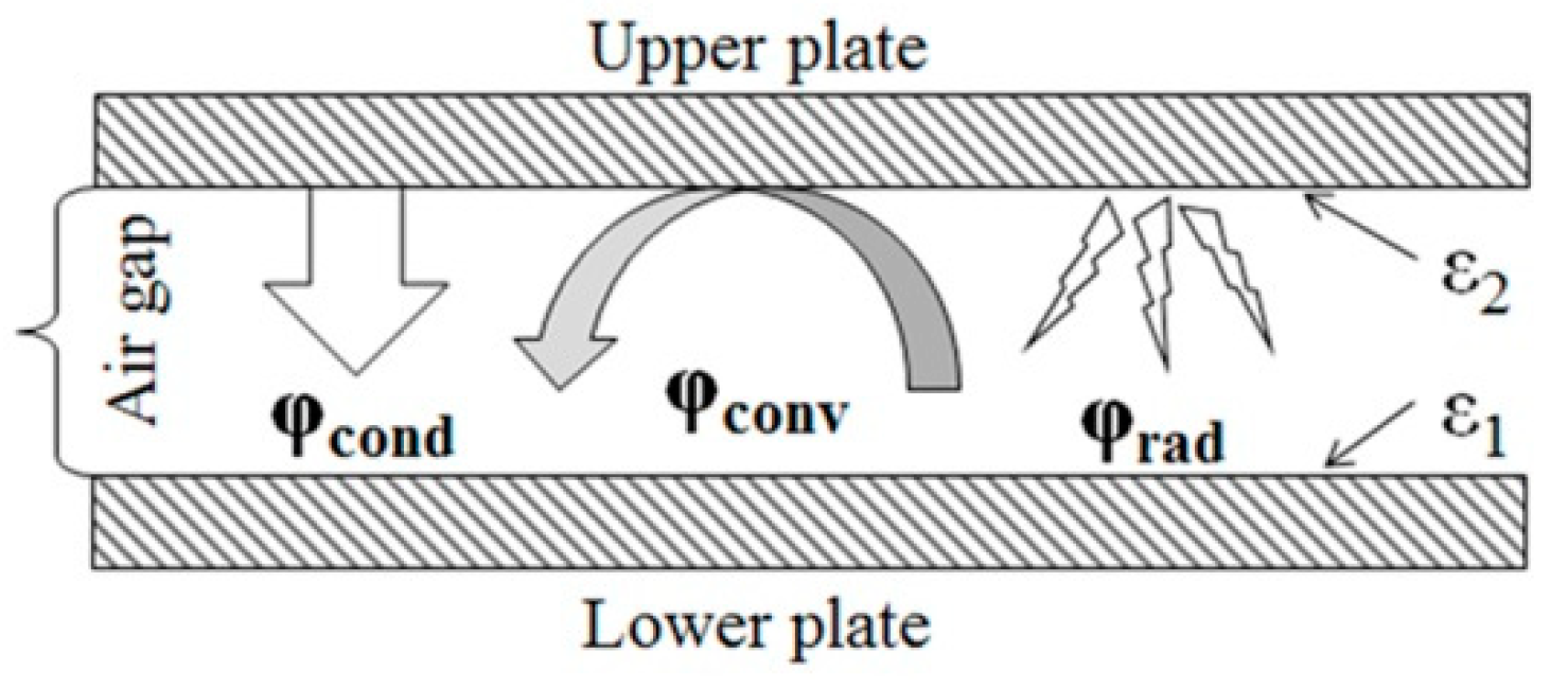
A calorimetric method for determining the emissivity (“measurement of heat lost or gained by a specimen through radiant heat transfer” [18]) is presented in [7]. The method consists in the adoption of a heat flow meter apparatus. The instrument can directly measure the total specific heat flow between two flat parallel surfaces (upper plate and lower plate). In Figure 2 the heat transfer contribution between the plate of the instrument are represented.
Assuming that the convection heat transfer can be considered suppressed for small air gaps [20], the total specific heat flow φtot (W/m2) measured by the apparatus can be written as in (Equation (2)):
φ tot = φ rad + φ cond = φ rad + λ s Δ T
where:
  • λ represents the thermal conductivity of still air calculated according to Equation (4) [21].
  • φrad (W/m2) is calculated according to Equation (3) [7].
    φ rad = 4 σ T m 3 Δ T ( 1 ε 1 ) + ( 1 ε 2 ) 1
  • ΔT is the temperature difference between the upper and the lower plate surfaces (K);
  • σ is the Stefan–Boltzmann’s constant = 5.67 × 10⁻⁸ W/(m2 K4);
  • ε1 and ε2 are the emissivities of the lower and upper surface respectively;
  • Tm is the average temperature between the two surfaces.
    λ air = 0.0242396   ( 1 + 0.003052   T 1.282 10 6 T 2 )
where T is the average air temperature given in (°C).
Assuming that the upper and lower surfaces have the same emissivity, it is possible to simplify Equation (3) in Equation (5):
φ rad = 4 σ T m 3 Δ T 2 ε
The total specific heat flow can be calculated as the sum of the radiation and conduction contributions to the overall specific heat flow φtot (Equation (6)).
φ tot = 4 σ T m 3 Δ T 2 ε + λ s Δ T
Hence, the emissivity ε can be determined as follows (Equation (7)):
ε = 2 ( φ tot ( λ / s )   Δ T ) 4 σ T m 3 Δ T φ tot ( λ / s )   Δ T
The method presented in [7] can be ideally applied if the emissivity of the two surfaces of the HFM apparatus is identical. Nevertheless, coating both the instrument plates can be a non-trivial task. For this reason, in the following section, the adaptation of the method to measure the emissivity of paints and coatings only placed on one side of the experimental apparatus is presented.

2.1.1. Application of the HFM Measurement Method

For the experimental analysis, a TA instrument—FOX 600, single sample Heat Flux Meter (HFM) apparatus was used, the main characteristic of the device are resumed in Table 1.
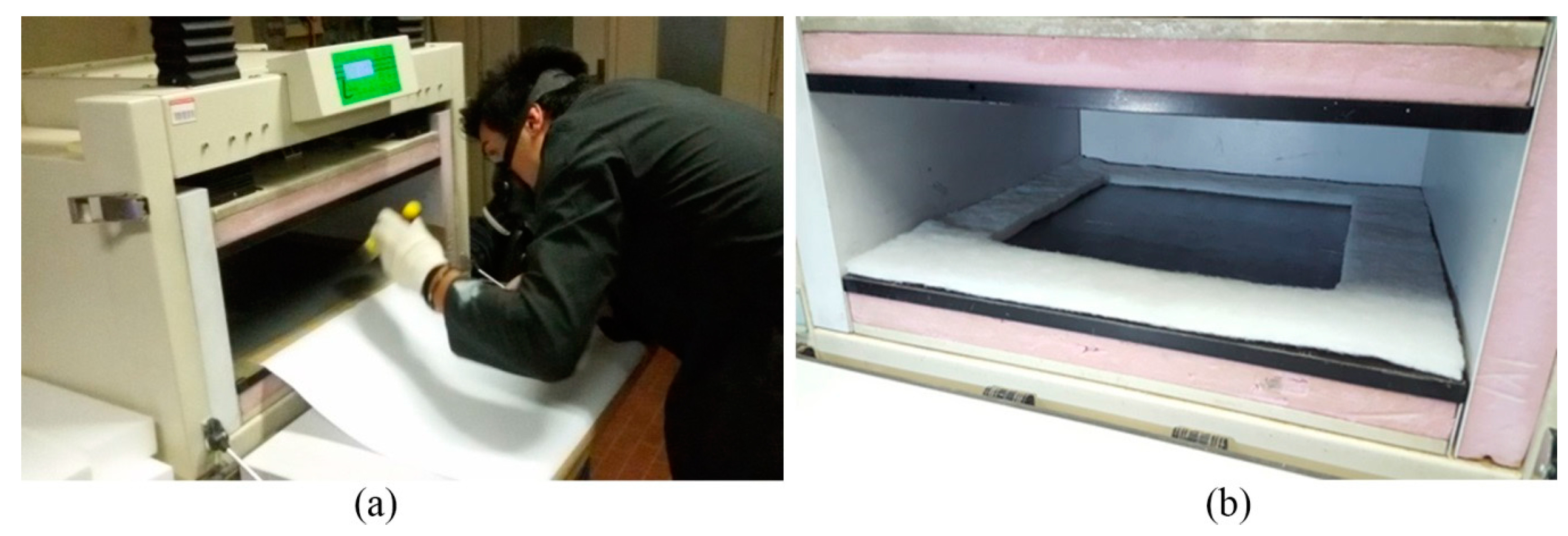
Only the lower plate surface was taped with a vinyl foil and then painted with a low emissivity paint or coated with aluminium foil since the painting of both the upper and the lower surfaces results costly from the point of view of the preparation of the experiments, as illustrated in Figure 3a. For this reason, the measurement was carried out in two steps. In the first step, the emissivity of the uncoated heat flux meter plate was determined according to Equation (8). In the second step, the measurements of the radiation specific heat flow were carried out with one coated surface according to Equation (9). To avoid the lateral heat losses, the measurement was performed placing a soft ring of polyester fibre between the two HFM plates and maintaining a central empty area of 400 × 400 mm2 (Figure 3b), while the instrument measurement area is 254 × 254 mm2 (the effective area where the sensors are placed)
φ rad = σ ( T 1 4 T 2 4 ) 1 ε 1 + 1 ε 2 1
Subsequently, the coating emissivity ε1 was determined by replacing ε2 in Equation (8) with the previously measured ε of the uncoated HFM plates.
ε 1 = φ rad ε 2 φ rad ( ε 2 1 ) + σ ε 2 ( T 1 4 T 2 4 )
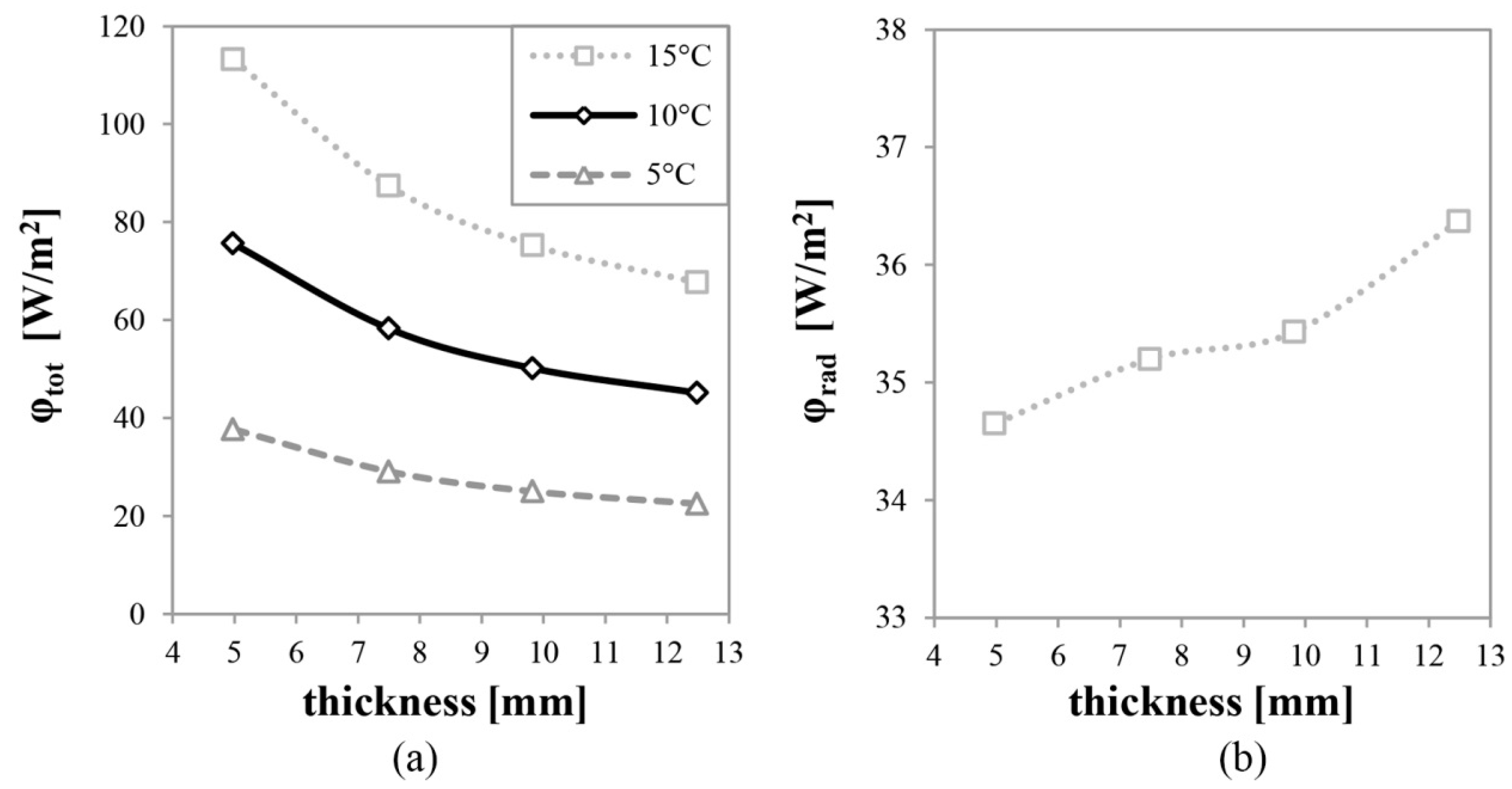
As mentioned in Section 2.1, the described methodology can only be adopted if convection heat transfer contributes is suppressed. A preliminary measurement campaign was performed changing the air gap thickness (from ~5 to ~12.5 mm) and the temperature difference between the HFM plates (from 5 to 15 °C) while the average temperature between the upper and lower plate (Tm) was kept constant at 25 °C, to verify this hypothesis and identify the measurement condition to be utilized for further analyses. Moreover, only downward heat fluxes were applied to reduce the buoyancy effects.
Table 2 resumes the measured values of specific heat flow and emissivity, while the measured total specific heat flow and the radiation heat transfer contribution are plotted in Figure 4a,b, respectively. As it is possible to observe, the determined emissivity does not present any dependency by the temperature difference, i.e., with 5 mm of the air gap thickness the variation of emissivity is negligible (from 0.410 to 0.412). Nevertheless, a small but not insignificant influence on the measured emissivity is due to the variation of the thickness s. This variation is also visible in Figure 4b, which shows the higher measured value of radiation heat transfer φrad for 12.5 mm air gap (+5% if compared to 5 mm air gap), while from 5 to 10 mm the differences are lower than 2.5% and can be considered to be negligible.
It is possible to assert that the increase of φrad can be attributed to the unsuppressed convection heat transfer, which became significant for thickness > 10 mm, since radiation heat transfer cannot be influenced by the air gap thickness.
The illustrated results highlight that the presented methodology can be adopted if the air gap thickness is <10 mm and if downward heat flux is applied by the HFM apparatus.

2.1.2. Measurements on Different Low-E Paint

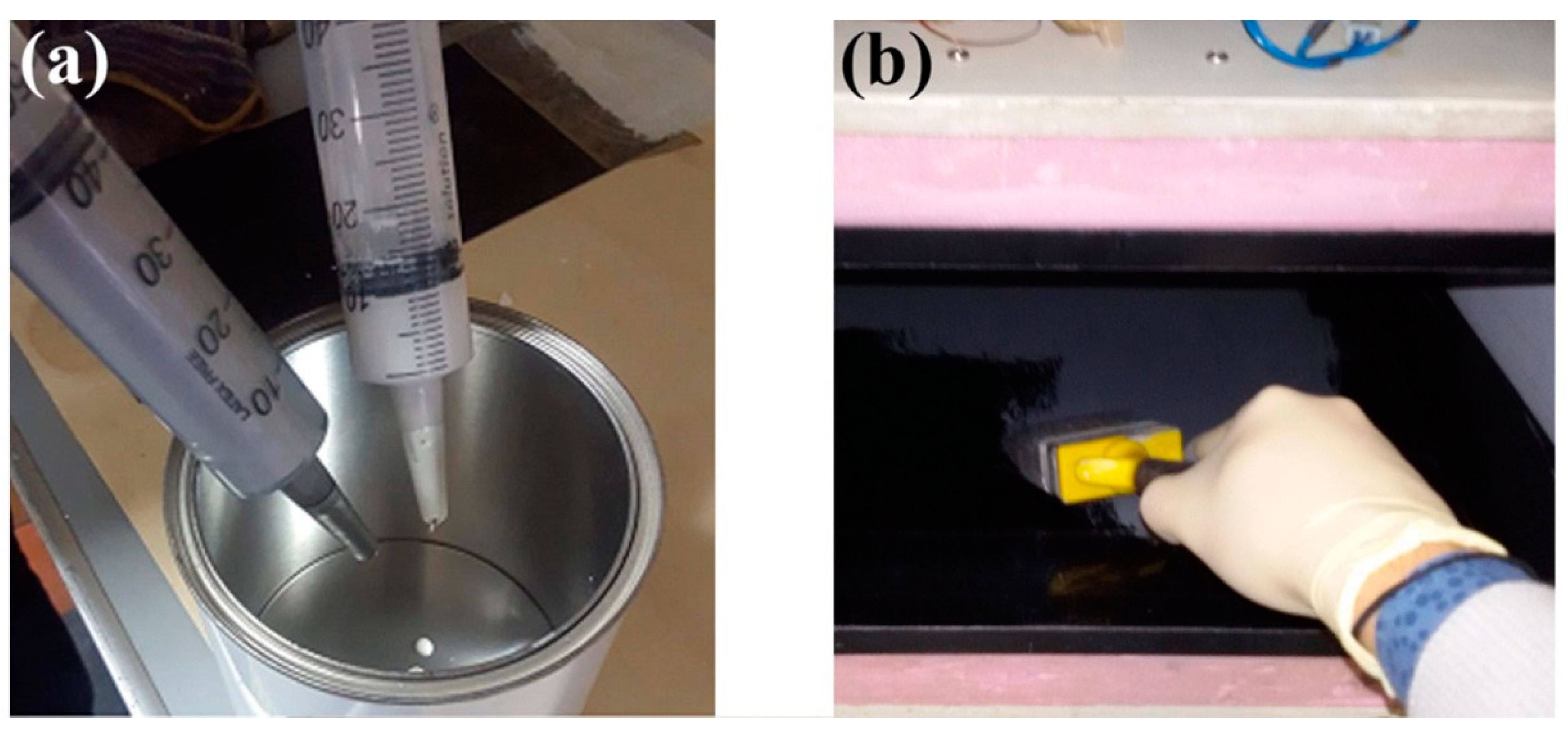
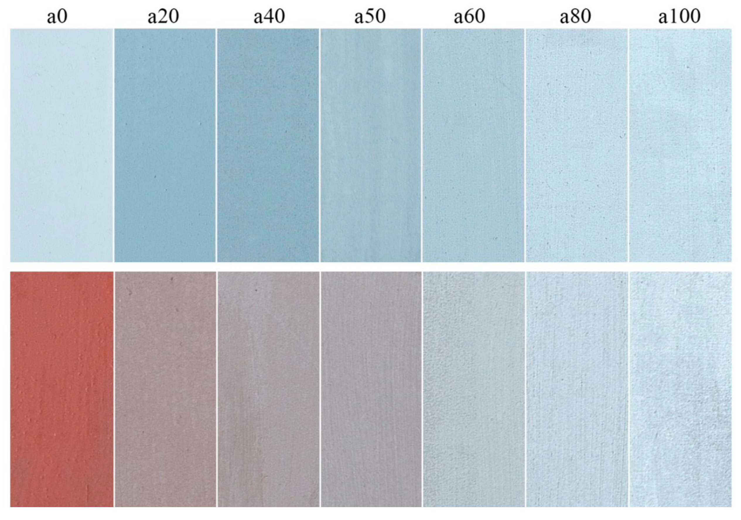
The aim of the presented study is to analyse the effect of the aluminium paint content and the impact on the final emissivity values. For this reason, different paints mixtures were prepared by mixing a commercial aluminium paint with matt paint, as illustrated in Figure 5a, and then all of the mixtures were applied on the lower surface of the HFM apparatus (Figure 5b). The emissivity values were measured as illustrated in Section 2.1.1. Table 3 reports the Al paint concentration of all the measured mixtures. Moreover, in Figure 6, a photographic survey of the different paint mixture (sample “a” series) is reported.

2.2. Analysis at Room Level

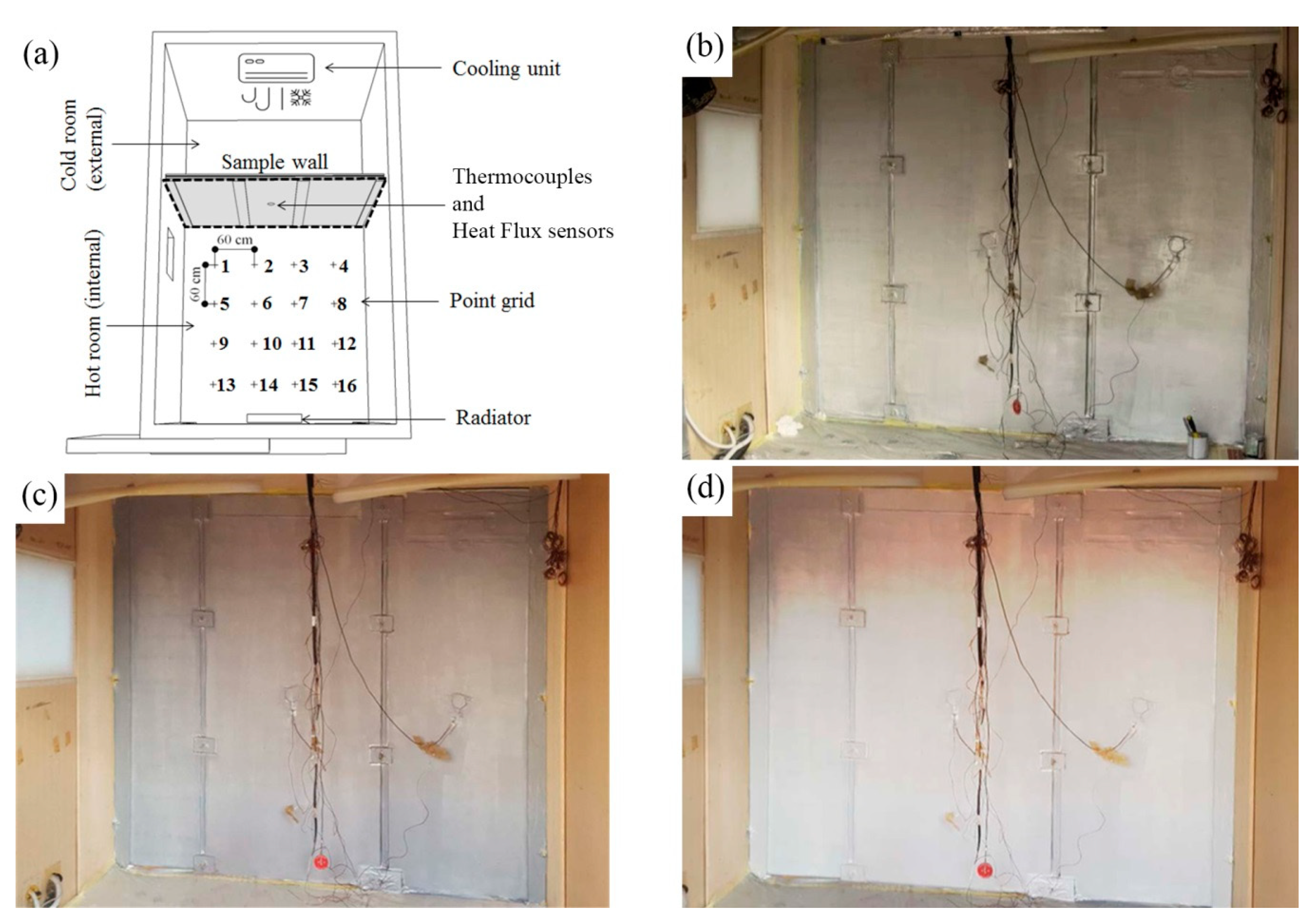
The analysed room having a dimension of 312 cm length, 272 cm depth, and 241 cm height, was heated at 22 ± 0.3 °C by using an electric radiator placed in the opposite side of the coated wall. The cold room representing the exterior environment was maintained at 10 ± 1 °C by a direct expansion cooling system (Figure 7a).
The party-wall is made by 6 mm thick MDF board (Medium Density Fibreboard), with a thermal conductivity λ of 0.102 ± 0.002 W/m K (previously measured by HFM apparatus).
The wall thermal behaviour was monitored by placing two heat flux sensors HFP02 (uncertainty < 3%) and six thermocouples (uncertainty < ±0.25 °C) for the measurement of the air and surface temperatures on both sides of the wall.
The experiments were repeated for three wall configurations, with each configuration being coated on the interior side with different paints described in Section 2.1.2:
  • Config. 1: a100 paint (ε = 0.41) (Figure 7b);
  • Config. 2: a50 paint (ε = 0.60) (Figure 7c); and,
  • Config. 3: a0 paint (ε = 0.88) (Figure 7d).
The wall thermal transmittance U was determined by applying the average method according to ISO 9869-1:2015 standard [22] (Equation (10)). Moreover, Equation (11) determines the indoor surface heat transfer coefficient.
U = J = 1 n φ j J = 1 n ( T air , i , j T air , e , j )
h i = J = 1 n φ j J = 1 n ( T air , i , j T s , i , j )
where: φ is the specific heat flow measured through the partition wall (W/m2); Ts,i is the internal surface temperature (°C); and, Tair,i and Tair,e are, respectively, the internal (heated room) and external (cooled room) air temperature.

Thermal Comfort Measurements

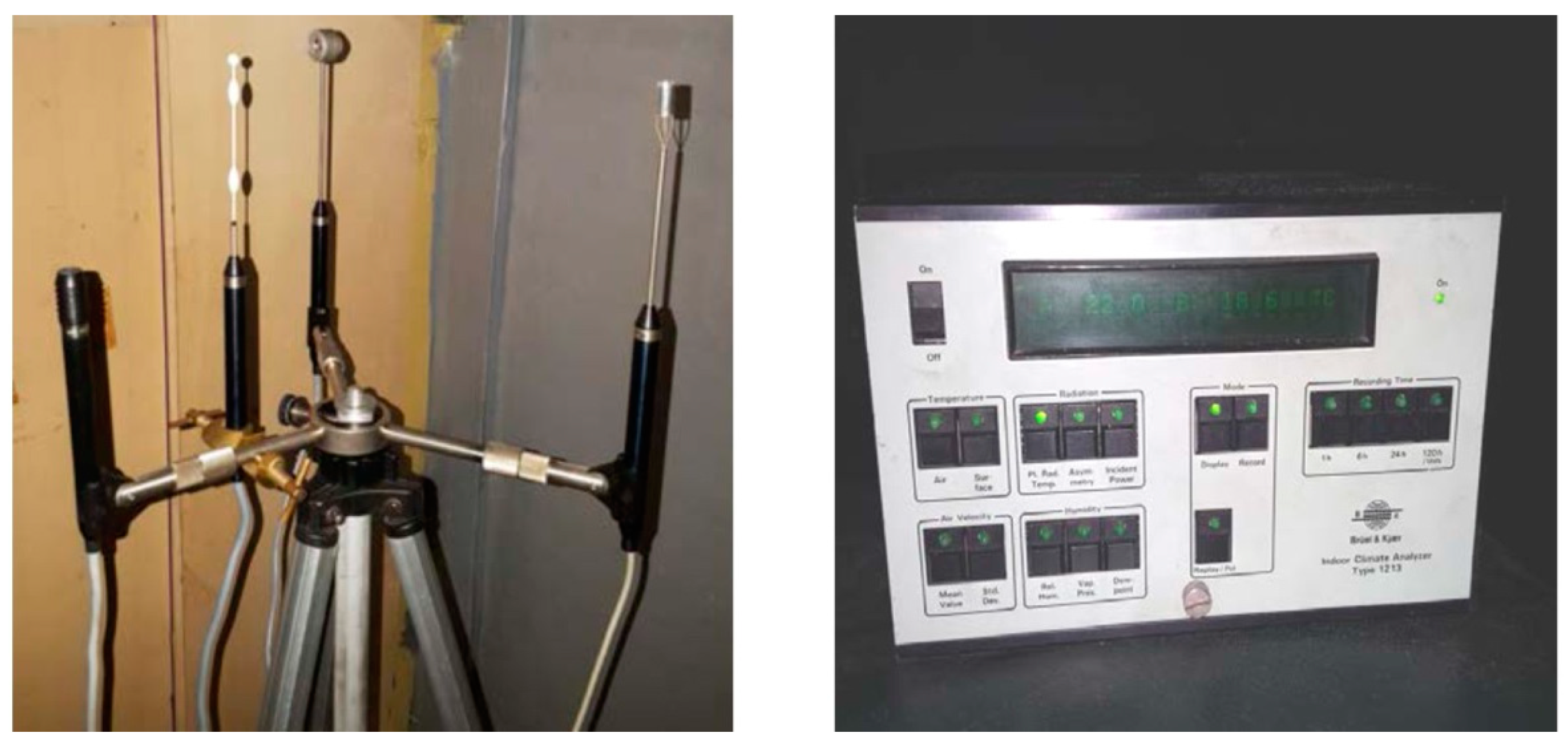
The measurements of the parameters to be adopted for the determination of the thermal comfort conditions were performed by using a Brüel & Kjær—Indoor Climate Analyzer n.1213 (Figure 8) [23]. The instrument is equipped with a hygrometer, a dry bulb temperature sensor, a hot-wire anemometer, and a net radiometer for the measurement of the planar radiative temperature.
A grid of sixteen points with equidistance of 60 cm was defined to mapping the indoor conditions, as illustrated in Figure 7a (Section 2.2). The sensors were positioned to measure the operative temperature at 60 cm height.
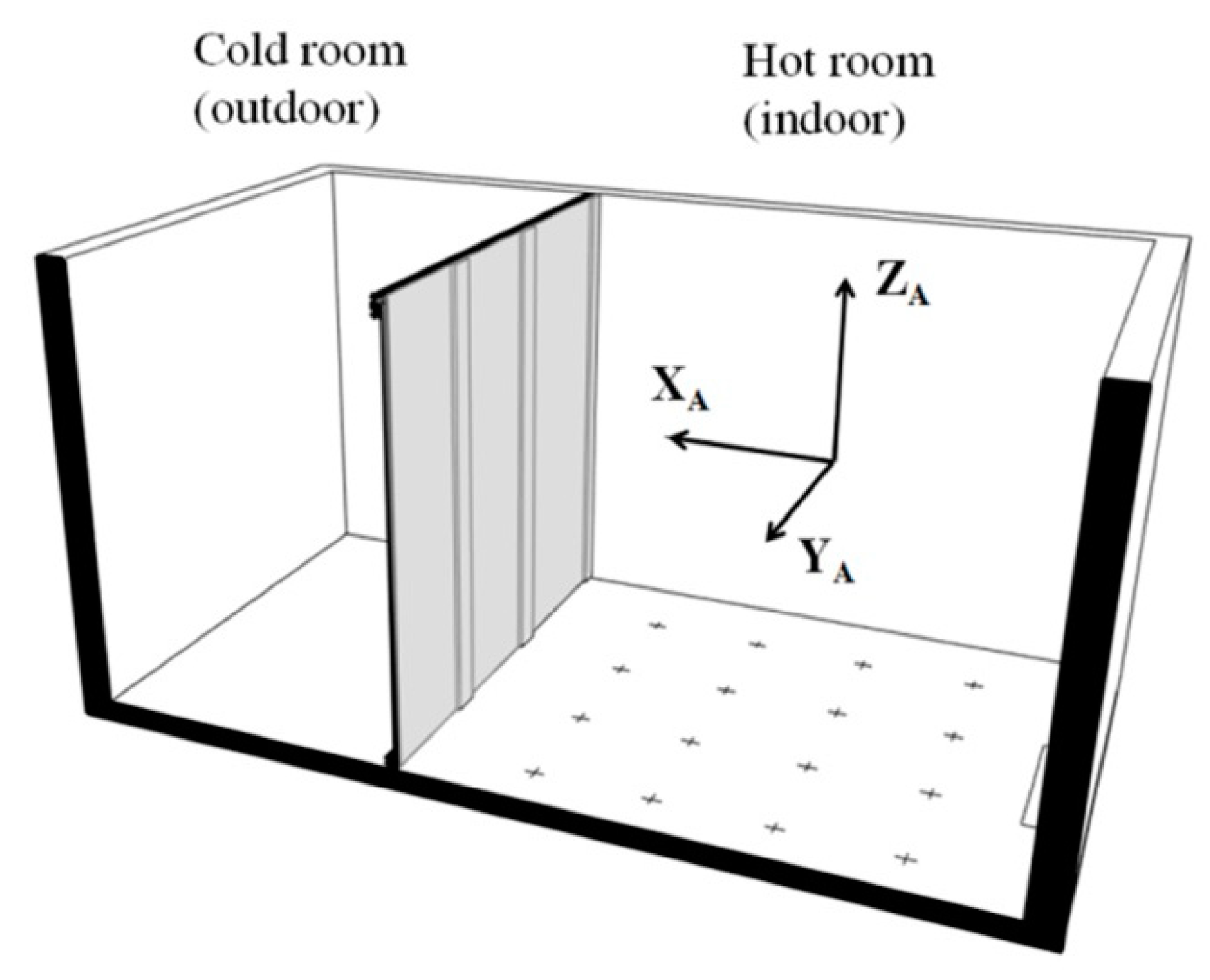
For each point, the mean radiant temperature Tmr was calculated by measuring the planar radiative temperature Tpr-i in the six directions of the space (up, down, left, right, front, and back) and the projected surface factor Ap-i for a person in the six direction of the space by using (Equation (12)) [23]:
T m r = ( i = 1 6   T p r i A p r i ) ( i = 1 6   A p r i ) 1
where, for a sitting person the projected surface factor Ap-i correspond to 0.3 (X-axis), 0.22 (Y-axis), and 0.18 (Z-axis) (Fanger 1970 [24]) (Figure 9).
For moderate indoor thermal environment if Tmr Tair < 4 °C and for air velocity v < 0.2 m/s the operative temperature Top can be determined by the average between the mean radiant temperature Tmr and the room air temperature Tair (Equation (13)):
T o p = T m r + T a i r 2
The PMV (predicted mean vote) and the PPD (predicted percentage dissatisfied) were calculated according to [25], while assuming a metabolic rate of 1 (met) and thermal resistance of the clothes of 0.9 (clo).

3. Results

3.1. Results at the Material Level

The experimental results that were obtained with the procedure described in Section 2.1.1 are summarised in Table 4. The measured emissivity of the aluminium foil and of the pure aluminium paint are respectively ~0.04 (sample c) (The emissivity ε ~ 0.04 of a commercial shine alluminium foil (sample c) was also measured by using a portable emissiometer according to ASTM C1371-15 [19]) and ~0.41 (sample a100). It is worth to be mentioned that these results are in line with the values reported in ([5,7,18]).
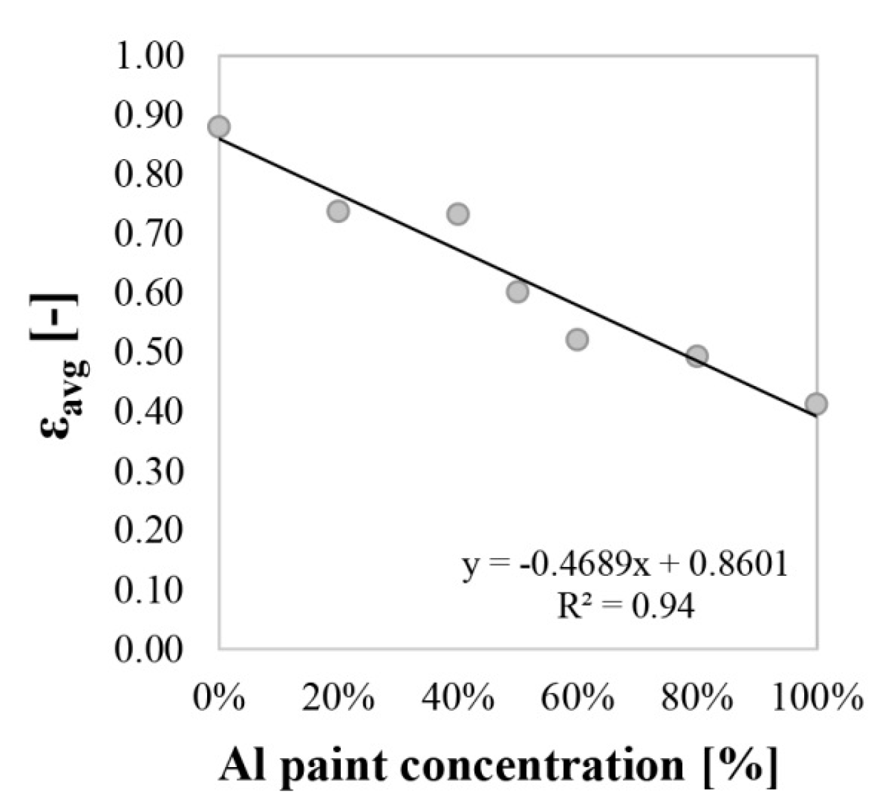
In Figure 10, a linear dependency of the emissivity as a function of the Al paint concentration is demonstrated. The results reveal that a change of 10% in the balance between the Al paint and the matt paint can determine a variation of approximately 0.047 of the final emissivity of the sample.
One of the main drivers for a large diffusion of these materials is to minimise the metallized effect of the finishing since these paints can be used as interior radiation control coating in buildings. Considering this aspect, an interesting result in terms of emissivity value (ε ~ 0.6) was reached by the sample a50 (50% of aluminium paint concentration). As demonstrated in the following section this material can have a non-negligible influence on the indoor mean radiant temperature with a valuable aesthetic value (Figure 6).

3.2. Results at Room Level

The influence of low emissivity coatings that were applied to the interior side of one external wall turned out a slight, but not marginal contribution for the reduction of the heat losses through the external walls (Figure 11) that can be summarised, as follows:
  • the application of a100 paint (ε = 0.41) show a reduction of ~35% of the surface heat transfer coefficient hi both in measurements and in the results that were obtained by applying the ISO 6946:2007 (Table 5); and,
  • the application of a50 paint (ε = 0.60) show a reduction of ~19% of the surface heat transfer coefficient hi, similar results with a reduction of ~21% was obtained calculating hi (predicted) according to ISO 6946:2007 (Table 5);
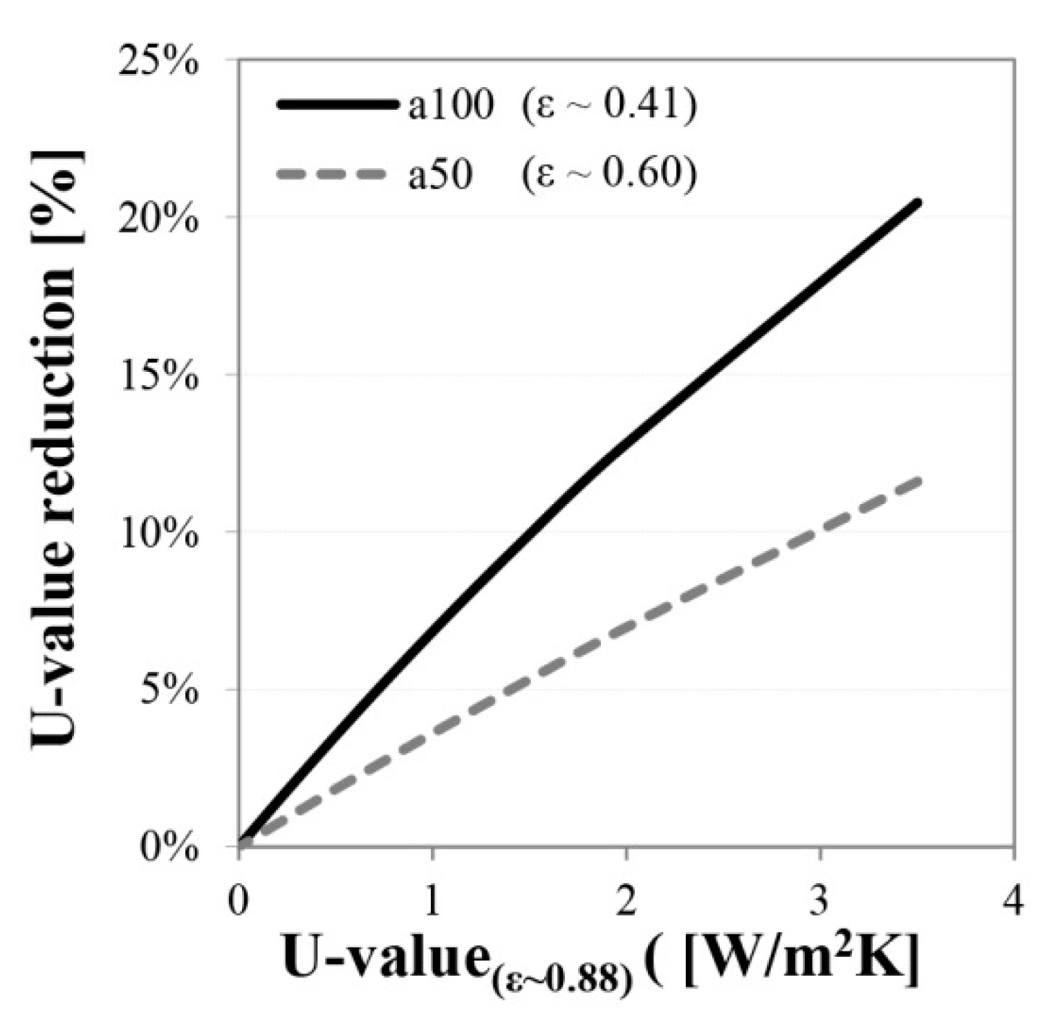
As expected, the reduction of the surface heat transfer coefficient affects the resulting U-value. In this specific case, it has to be underlined that, for research purposes (reduce the heat flux measurement uncertainty), an unrealistic wall component (6 mm of MDF) was used for the experiments. For building components that are characterised by poor insulating properties, the surface heat transfer represents the main driver of the U-value and this explains the high reduction of U-value up to 20% (Figure 11b). However, this reduction is not realistic, since uninsulated wall components very rarely present U > 1.5–2 W/m2 K, which means that, in real situations, a reduction of the U-value higher than 10% cannot be achievable. For moderately insulated building components, i.e., characterised by U = 0.5 W/m2 K, the achievable reduction decrease below 4%, as can be observed in Figure 12. These results are in line with those that were reported by [16]: in fact, considering that heat losses through opaque building envelope account only for a fraction of the heating energy consumption, solutions that claim energy savings above 5% (even with minor emissivity) should be considered with some skepticism.
Furthermore, important shortcomings should be highlighted: an undesirable effect of the reduction of the surface heat transfer coefficient determines a lowering of the indoor surface temperature (up to 1.5 °C of reduction was observed by applying paint with ε = 0.41); this effect, which is clearly represented in Figure 11a, can determine surface condensation and mould growth. For this reason, the feasibility of the intervention should be carefully verified before applying low emissivity paints in both uninsulated walls and in walls that still present moisture-related pathologies.
As discussed, the application of low emissivity paints benefits of the reduction of heat losses through the opaque components. Nevertheless, another not negligible benefit can be the improvement of the indoor comfort conditions. The results of the measurements with the indoor climate analyser for each measurement point are reported in Table A1 (Appendix A). Moreover, Table 6 summarises the average results. As illustrated, the results show that the application of low emissivity paints a100 and a50 determines:
  • an increase of the average mean radiant temperature of up to ~0.9 (ε = 0.41) and up to ~0.5 °C (ε = 0.6) respect to the high emissivity paint (ε = 0.88);
  • a slight increase in the average operative temperature of the room of ~0.6 and ~0.3 °C respectively with the a100 and the a50 paint;
  • an improvement of the indoor comfort condition. The PMV change from −0.56 with a0 paint (comfort category C [25]) to −0.40 and −0.47 (comfort category B [25]) with the low emissivity paints a100 and a50 respectively;
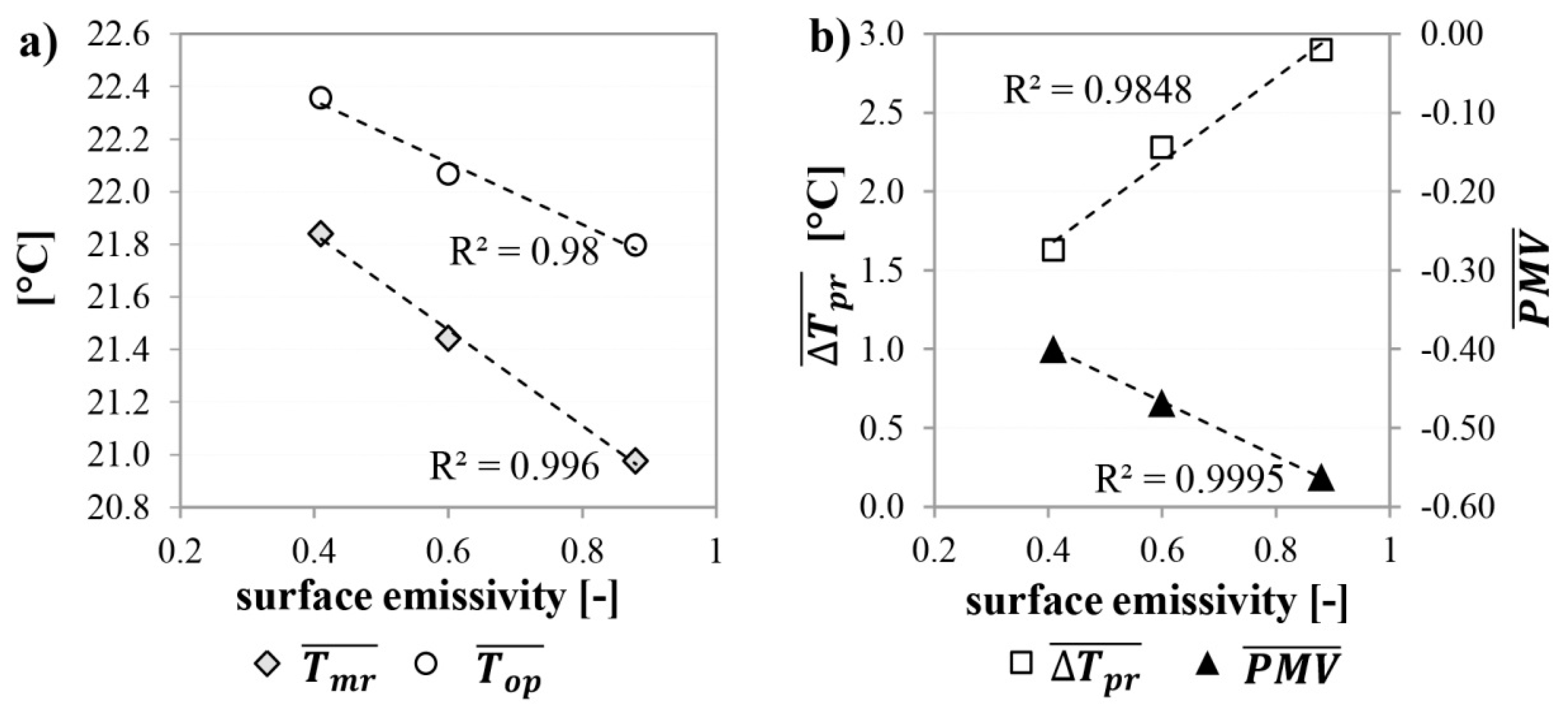
  • linear increase of the T m r ¯ , the T o p ¯ and the PMV according to the decrease of the surface emissivity (Figure 13); and,
  • a decrease of the average radiant planar asymmetry along the X-axis from 2.90 °C (ε = 0.88) to 1.63 °C (ε = 0.41).

4. Conclusions

In this study, a procedure for the determination of the thermal emissivity by Heat Flux Meter Apparatus has been presented. The developed method was used to measure the infra-red emissivity of paints mixtures containing a different percentage of aluminium paint. The results show a variation of the emissivity from 0.41 to 0.88, depending on the aluminium paint concentration. It is worth noting that the paint mixture containing a 50% of aluminium paint with a reduced metallized effect present a reduction of emissivity in comparison to a matte paint from 0.88 to 0.60. The results are encouraging and they highlight that paints with good aesthetic value (limited metalized effect), and reduced emissivity, can be specifically developed for the application as interior radiation control coating.
Furthermore, the effect of the different Interior Radiation Control Coatings IRCC was investigated through an experimental campaign in a double climatic chamber apparatus. The experimental results demonstrate that the application of IRCC determines:
  • a significant reduction of the indoor surface heat transfer coefficient, respectively of ~35% with 100% aluminium paint and 19% with 50% aluminium paint that can result in the slightly but non-negligible reduction of the wall heat losses (especially in non-insulated walls);
  • a decrease of the measured wall U-value above 20% (from 3.49 to 2.74 W/m2 K) with a 100% aluminium paint. However, it is worth mentioning that, for a slightly insulated wall (U-value = 0.5 W/m2 K), the U-value reduction that can be achieved is below 4%, meaning that the effect of the low emissivity coating is negligible for more insulated building components; and,
  • an increase of the indoor mean radiant temperature of ~0.9 °C and ~0.5 °C and of the operative temperature of ~0.6 °C and ~0.3 °C respectively with 100% and 50% of aluminium paint.
The above-mentioned results highlight that the application of IRCC shows a slight improvement of the indoor comfort condition as well as a marginal reduction of the heat losses. However, the results are encouraging especially considering that:
  • IRCC represents a low-cost solution that can be easily applied on the interior side of the external walls;
  • IRCC can be easily coupled with other insulating technologies (i.e., aerogel rendering and coatings [17]) making it a promising solution for all the interventions, in which space-saving represents a constraint; and,
  • further improvements in the paint emissivity properties can be achieved working towards optimization of the final mixture.
Moreover, possible higher exploitation of these materials can be envisioned in envelopes for special environments i.e., ice rinks, temporary buildings, automotive, and marine sector.

Author Contributions

All the authors contributed equally to the conception, the design, the experimental campaigns and the writing of this paper. All authors have read and agreed to the published version of the manuscript.

Funding

This research received no external funding.

Acknowledgments

The authors want to express their gratitude to Arch. Simone Palermo for helpful support during the experimental activities. Moreover, the authors wish to thanks Michele Zinzi (ENEA) and Francesco Bianchi (University of Perugia) that have provided the emissivity data of the aluminium foil measured through a portable emissiometer device.

Conflicts of Interest

The authors declare no conflict of interest.

Appendix A

Table A1. Results output from comfort meter measurements.
SamplePointDistance from WallTairRHvairTpr,XBTpr,XATpr,YBTpr,YATpr,ZBTpr,ZATmrTopPMVPPD
[m][°C][%][m/s][°C][°C][°C][°C][°C][°C][°C][°C][-][%]
a010.622.7420.0021.818.221.420.020.621.120.4421.57−0.612.5
20.622.6420.0121.818.321.320.220.621.120.4821.54−0.612.5
30.622.7420.0121.818.421.420.220.521.220.5121.61−0.612.5
40.622.6420.0221.818.321.520.320.621.120.5221.56−0.612.5
51.222.6420.0122.018.521.720.621.121.720.8321.71−0.612.5
61.222.7420.0221.918.521.720.721.221.620.8221.76−0.612.5
71.222.7420.0422.018.421.820.721.321.820.8821.79−0.612.5
81.222.6420.0422.018.521.820.921.321.920.9421.77−0.612.5
91.822.5420.0222.019.321.921.021.222.021.1521.82−0.612.5
101.822.7420.0221.819.421.820.921.222.121.1121.90−0.510.2
111.822.6420.0021.919.521.821.021.322.121.1821.89−0.612.5
121.822.5420.0122.019.521.821.021.422.221.2221.86−0.510.2
132.422.7420.0222.119.922.021.121.522.021.3722.03−0.510.2
142.422.6420.0221.919.821.921.221.622.221.3421.97−0.510.2
152.422.6420.0222.020.022.021.121.722.121.4022.00−0.510.2
162.422.5420.0222.120.022.021.121.622.221.4321.96−0.510.2
a5010.622.6420.0322.319.021.120.720.421.520.8121.70−0.612.5
20.622.5420.0222.119.121.120.920.321.720.8321.66−0.612.5
30.622.5420.0322.319.021.221.020.221.520.8421.67−0.612.5
40.622.7420.0122.319.121.321.220.421.620.9521.83−0.510.2
51.222.7420.0322.319.721.521.320.722.021.2221.96−0.510.2
61.222.8420.0222.419.921.521.420.822.121.3222.06−0.510.2
71.222.6420.0222.319.921.621.620.922.321.3921.99−0.510.2
81.222.6420.0222.420.021.721.721.022.221.4622.03−0.510.2
91.822.7420.0322.320.421.921.821.222.121.5822.14−0.48.3
101.822.7420.0322.420.521.921.721.222.221.6222.16−0.48.3
111.822.8420.0222.620.722.021.821.322.221.7522.28−0.48.3
121.822.8420.0222.520.722.022.021.322.321.7822.29−0.48.3
132.422.7420.0422.620.822.122.021.422.321.8522.27−0.48.3
142.422.8420.0222.621.022.222.121.522.121.9122.36−0.48.3
152.422.8420.0322.521.022.222.021.522.321.9022.35−0.48.3
162.422.8420.0222.421.122.322.021.422.121.8822.34−0.48.3
a10010.622.7420.0322.119.821.320.920.621.220.9821.84−0.512.5
20.622.7420.0122.520.121.221.120.821.421.2021.95−0.512.5
30.622.8420.0222.420.021.421.120.821.521.2022.00−0.512.5
40.622.9420.0322.420.221.621.521.021.621.3822.14−0.512.5
51.222.8420.0122.720.621.921.821.322.021.7122.26−0.48.3
61.223.0420.0222.720.621.821.621.521.921.6822.34−0.48.3
71.222.9420.0322.620.622.021.621.522.021.7022.30−0.48.3
81.222.9420.0122.720.822.022.021.522.121.8422.37−0.48.3
91.823.0420.0322.621.322.322.221.922.322.0822.54−0.48.3
101.823.0420.0222.821.322.422.122.122.322.1522.58−0.36.9
111.822.9420.0322.721.522.322.022.022.222.1222.51−0.48.3
121.822.7420.0322.621.522.322.221.922.222.1122.41−0.48.3
132.422.8420.0322.521.722.522.422.222.522.2722.54−0.48.3
142.423.0420.0222.821.722.222.722.222.522.3422.67−0.36.9
152.423.0420.0322.721.722.522.122.622.422.3122.65−0.36.9
162.422.9420.0222.621.922.522.322.622.322.3522.62−0.36.9

References

  1. Lee, S.W.; Lim, C.H.; Salleh, E.I.B. Reflective thermal insulation systems in building: A review on radiant barrier and reflective insulation. Renew. Sustain. Energy Rev. 2016, 65, 643–662. [Google Scholar] [CrossRef]
  2. Krnst, S. Heat Insulation. U.S. patent 1890418 A, 6 December 1932. [Google Scholar]
  3. Eduard, D. Heat Insulation for Air Spaces. U.S. patent 1934174 A, 7 November 1933. [Google Scholar]
  4. Hens, H. Building Physics: Heat, Air and Moisture. Fundamentals and Engineering Methods with Examples and Exercises, 2nd ed.; Ernst & Sohn GmbH & Co. KG: Berlin, Germany, 2012. [Google Scholar]
  5. Incropera, F.P.; DeWitt, D.P. Fundamentals of Heat and Mass Transfer, 3rd ed.; Wiley: Hoboken, NJ, USA, 1990. [Google Scholar]
  6. Reflective Insulation Manufacturers Association International (RIMA-I). Understanding and Using Reflective Insulation, Radiant Barriers and Radiation Control Coatings. 2014. Available online: http://www.insulationstop.com/radiant-barrier-blog/updated-handbook-understanding-using-reflective-insulation-radiant-barrier-irccs/ (accessed on 24 December 2019).
  7. Jelle, B.P.; Kalnæs, S.E.; Gao, T. Low-emissivity materials for building applications: A state-of-the-art review and future research perspectives. Energy Build. 2015, 96, 329–356. [Google Scholar] [CrossRef] [Green Version]
  8. Fantucci, S.; Serra, V. Low-E paints enhanced building components: Performance, limits and research perspectives. Energy Procedia 2017, 126, 274–281. [Google Scholar] [CrossRef] [Green Version]
  9. Fantucci, S.; Serra, V.; Martinelly, A. Thermal effectiveness of low emissivity coatings in hollow bricks: A numerical analysis for different cavity concentration. In Proceedings of the 9th IMC “International Masonry Conference”, Guimarães, Portugal, 7–9 July 2014. [Google Scholar]
  10. Principi, P.; Fioretti, R. Thermal analysis of the application of pcm and low emissivity coating in hollow bricks. Energy Build. 2012, 51, 131–142. [Google Scholar] [CrossRef]
  11. Principi, P.; Fioretti, R. Thermal Performance of Hollow Clay Brick with Low Emissivity Treatment in Surface Enclosures. Coatings 2014, 4, 715–731. [Google Scholar] [CrossRef] [Green Version]
  12. Sedlbauer, K.; Krus, M.; Fitz, C.; Künzel, H.M. Reducing the Risk of Microbial Growth on Insulated Walls by PCM Enhanced Renders and IR Reflecting Paints. In Proceedings of the International Conference on Durability of Building Materials and Components, XII DBMC, Porto, Portugal, 12–15 April 2011. [Google Scholar]
  13. Fantucci, S.; Serra, V. Investigating the performance of reflective insulation and low emissivity paints for the energy retrofit of roof attics. Energy Build. 2019, 182, 300–310. [Google Scholar] [CrossRef]
  14. Joudi, H.; Svedung, M.; Cehlin, M. Rönnelid. Highly reflective coatings for interior and exterior steel cladding and the energy efficiency of buildings. Appl. Energy 2011, 88, 4655–4666. [Google Scholar] [CrossRef]
  15. Joudi, H.; Svedung, M.; Cehlin, M. Rönnelid. Reflective coatings for interior and exterior of buildings and improving thermal performance. Appl. Energy 2013, 103, 562–570. [Google Scholar] [CrossRef]
  16. Buckmaster, D.J.; Abramson, A.R. The effects of interior emissivity and room layout on forced air space-conditioning power usage. Int. J. Heat Mass Transf. 2015, 89, 216–228. [Google Scholar] [CrossRef]
  17. Ibrahim, M.; Bianco, L.; Ibrahim, O.; Wurtz, E. Low-emissivity coating coupled with aerogel-based plaster for walls’ internal surface application in buildings: Energy saving potential based on thermal comfort assessment. J. Build. Eng. 2018, 18, 454–466. [Google Scholar] [CrossRef]
  18. Bagdade, S.D. ASM Ready Reference: Thermal Properties of Metals; Materials Data Series; ASM: Aimere, Netherlands, 2002. [Google Scholar]
  19. ASTM C1371-15. Standard Test Method for Determination of Emittance of Materials Near Room Temperature Using Portable Emissometers; ASTM: West Conshohocken, PA, USA, 2015. [Google Scholar]
  20. Tenpierik, M.J.; Hasselaar, E. Reflective multi-foil insulations for buildings: A review. Energy Build. 2013, 56, 233–243. [Google Scholar] [CrossRef]
  21. EN 1946-3. Thermal Performance of Building Products and Components—Specific Criteria for the Assessment of Laboratories Measuring Heat Transfer Properties—Part 3: Measurements by Heat Flow Meter Method; European Committee For Standardization (CEN): Brussels, BE, USA, 2004. [Google Scholar]
  22. ISO 9869-1. Thermal Insulation: Building Elements—In-Situ Measurement of Thermal Resistance and Thermal Transmittance. Part 1: Heat Flow Meter Method; ISO: Geneva, Switzerland, 2015. [Google Scholar]
  23. EN ISO 7726. Ergonomics of the Thermal Environment—Instruments for Measuring Physical Quantities; European Committee For Standardization (CEN): Brussels, BE, USA, 2001. [Google Scholar]
  24. Fanger, P.O. Thermal Comfort; Danish Technical Press: Copenhagen, Denmark, 1970. [Google Scholar]
  25. EN ISO 7730. Ergonomics of Thermal Environment—Analytical Determination and Interpretation of Thermal Comfort Using Calculation of the PMV and PPD Indices and Local Thermal Comfort Criteria; European Committee For Standardization (CEN): Brussels, BE, USA, 2006. [Google Scholar]
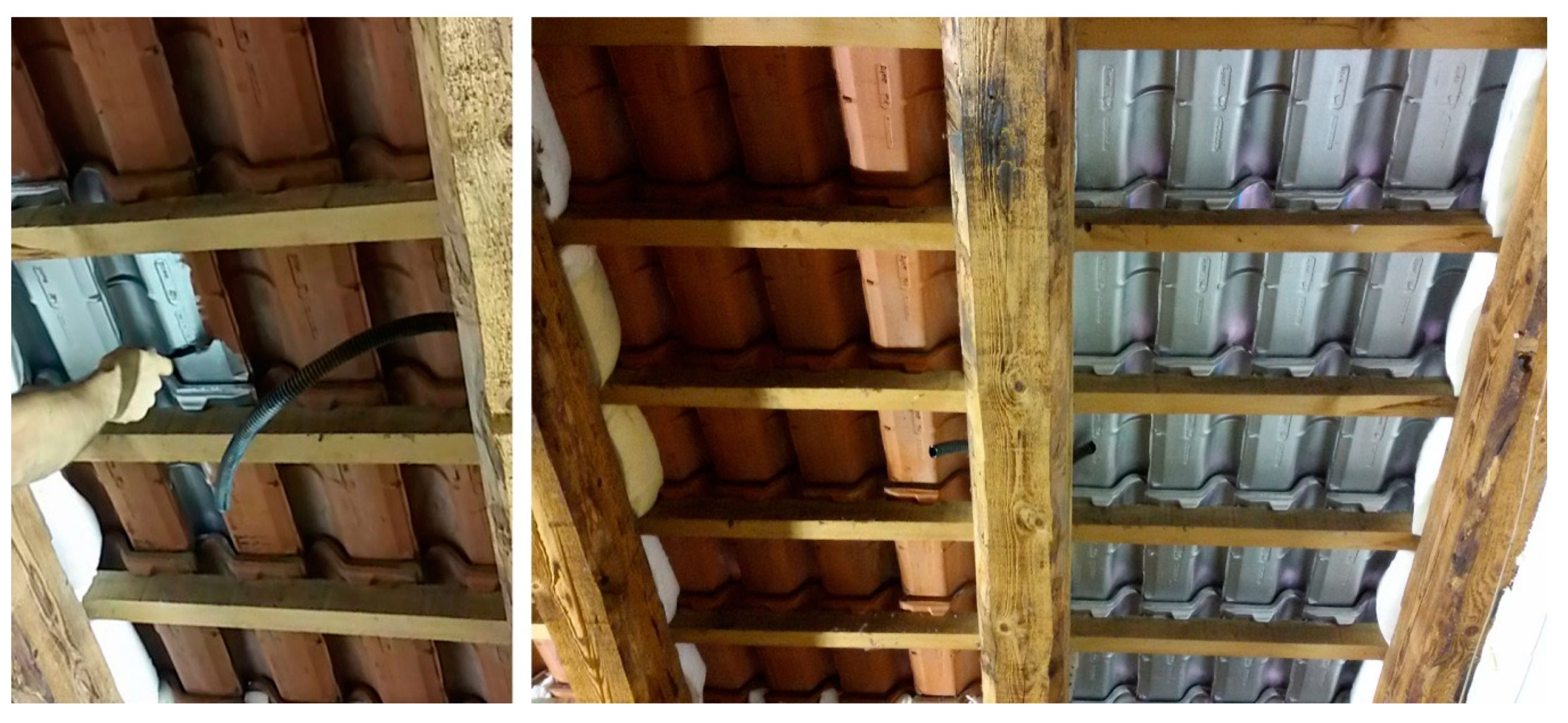
Figure 1. Application of an interior radiation control coatings (IRCC) in roof attic.
Applsci 10 00842 g001
Figure 2. Heat transfer contribution between two flat parallel plates divided by an air gap.
Applsci 10 00842 g002
Figure 3. (a) Coating of the lower Heat Flux Meter (HFM) plate; (b) Polyester ring.
Applsci 10 00842 g003
Figure 4. (a) Total specific heat flow; (b) Radiative specific heat flow (ΔT = 15 °C).
Applsci 10 00842 g004
Figure 5. (a) Preparation of the paint mixture; (b) application of the paint on the lower HFM surface.
Applsci 10 00842 g005
Figure 6. Photographic survey (samples a series); (up) Aluminium paint mixed with white matt paint; (down) Aluminium paint mixed with red paint.
Applsci 10 00842 g006
Figure 7. (a) Experimental test rig; (b) Sample C (a100 paint); (c) Sample B (a50 paint); and, (d) Sample A (a0 paint).
Applsci 10 00842 g007
Figure 8. Brüel & Kjær—Indoor Climate Analyzer n.1213.
Applsci 10 00842 g008
Figure 9. Axis orientation for the planar radiative temperature measurements Tpr.
Applsci 10 00842 g009
Figure 10. Sample (a) mixtures: emissivity as a function of the aluminium paint concentration.
Applsci 10 00842 g010
Figure 11. (a) Internal measured surface heat transfer coefficient hi and surface temperature Tsi as a function of the wall surface emissivity ε; and, (b) Measured U-values obtained with the different paints mixtures.
Applsci 10 00842 g011
Figure 12. Reduction of the U-value that can be achieved with a100 paint (ε ~ 0.41) and a50 paint (ε ~ 0.60) compared to the a0 paint (ε ~ 0.88) for different level of insulation.
Applsci 10 00842 g012
Figure 13. (a) Room average Tmr and Top results as a function of the wall surface emissivity; (b) average radiant planar asymmetry Δ T p r ¯   and average predicted mean vote P M V ¯   as a function of the wall surface emissivity.
Applsci 10 00842 g013
Table 1. Summary of the HFM apparatus specifications.
Temperature operation−15 °C to 85 °C
Temperature controlto 0.01 °C
Maximum specimen size610 × 610 mm
Measurement area254 × 254 mm
Conductivity range0.001 to 0.35 W/m K
Absolute accuracy±1%
Reproducibility±0.5%
Table 2. Experimental results: Specific heat flow φ and emissivity ε for different temperature difference and air gap thickness.
sΔTφtotφcondφradε
[mm][°C][W/m2][W/m2][W/m2][-]
12.481567.7031.3336.370.432
9.821575.2539.8235.430.420
7.491587.4352.2335.200.417
4.9815113.2078.5534.650.410
12.481045.1520.8824.260.433
9.821050.1726.5423.630.421
7.491058.3034.7923.510.418
4.981075.6352.4223.200.412
12.48522.5110.4412.060.430
9.82525.0113.2711.740.418
7.49529.1017.4011.700.416
4.98537.7226.1811.540.410
Table 3. Summary of the paint mixtures.
Sample NameAl Paint Concentration
[%]
a100100%
a8080%
a6060%
a5050%
a4040%
a2020%
a00%
c (reference aluminium foil)-
Table 4. Summary of the results obtained with the HFM procedure (5 mm thick air gap).
Sample NameAl Paint Concentration φ radε
[%][W/m2][-]
a100100%11.540.410
a8080%13.860.500
a6060%14.420.522
a5050%16.320.597
a4040%19.600.732
a2020%19.730.737
a00%23.040.881
c (reference aluminium foil)- 0.040
Table 5. Summary of the results obtained from the heat flux meter and the thermocouple measurements. Tair,i is the internal air temperature (heated room), Tair,e is the external air temperature (cooled room), Tsi is the internal surface temperature (heated wall side), and Tse is the external surface temperature (cooled wall side).
SampleTair,i
(Heated Room)
Tair,e
(Cooled Room)
Ts,iTs,eφhi (Measured)hi (Predicted)U
[°C][°C][°C][°C][W/m2][W/m2 K][W/m2 K][W/m2 K]
a10021.69.614.312.532.84.474.732.74
a5021.69.715.013.037.35.645.753.14
a021.69.915.813.640.46.937.253.49
Table 6. Summary of the results obtained from the Indoor Climate Analyzer. Tair is the average air temperature of the heated room.
Config T a i r ¯ T m r ¯ Δ T p r , X ¯ T o p ¯ P M V ¯ P P D ¯
[°C][°C][°C][°C] [%]
a10022.8821.841.6322.36−0.409.00
a5022.6921.442.2822.07−0.479.68
a022.6220.982.9021.80−0.5611.64