Article

Experimental and Numerical Energy Assessment of a Monolithic Aerogel Glazing Unit for Building Applications

1
Engineering Department, University of Perugia, Via G. Duranti n.67, 06125 Perugia, Italy
2
ENEA-National Agency for New Technologies, Energy and Sustainable Economic Development, Casaccia, Via Anguillarese n.301, 00123 Roma, Italy
*
Author to whom correspondence should be addressed.
Appl. Sci. 2019, 9(24), 5473; https://doi.org/10.3390/app9245473
Submission received: 7 November 2019 / Revised: 10 December 2019 / Accepted: 11 December 2019 / Published: 13 December 2019

Abstract

:
In the last few decades, the attention of researchers has been focused on the characterization of aerogels in order to improve the thermal performance of transparent building envelopes. Granular aerogel is already spread in the market thanks to the easy manufacturing system, whereas the difficulty in producing monoliths without defects, cracks, and inhomogeneity limited the diffusion of monolithic aerogel systems. A new production process for the monolithic panels was developed at Union College (Schenectady, NY, USA); it is a rapid supercritical extraction technique which allows a reduction in production time (only a few hours) and results in less solvent waste. Panes with maximum dimensions of about 100 × 100 mm were fabricated and composed in a unique glazing system, with external dimensions 300 × 300 mm. The thermal characterization of the innovative monolithic aerogel glazing system (simple float glazing 4.7-mm-thick monolithic aerogel pane 15-mm-thick simple float glazing 4.7 mm thick), which was carried out by means of a Small Hot Box apparatus, showed a thermal transmittance value of about 1.1 W/(m2K). Data was used in dynamic simulations of a typical non-residential building. They showed that the new investigated solution allows a valuable reduction with respect to a low-e double glazing system in terms of heating energy demand (about 5–7% for Helsinki, 8–12% for Paris, and 10–15% for Turin), for different window-to-wall ratios.

1. Introduction

Building envelopes consist of different structural and functional components, such as windows, walls, floors, and roofs; each of them plays an important role on the overall energy efficiency. Different technologies could be considered to improve building energy performance, especially focusing on the transparent elements; highly insulating glazing windows have been under rapid development in the last years and some commercial products have been used in many applications, both for new buildings and refurbishment [1,2]. A glazing system with aerogel filling is proposed as a technology able to offer natural light, with the advantage of better thermal insulation performance with respect to traditional double and triple glazing solutions [3,4]. Aerogel is a nanostructured solid material characterized by low density and high porosity (>90%), with a thermal conductivity lower than 0.020 W/mK. It comes in granular and monolithic form: granular aerogels are easy to handle because they could be poured like a powder [2], but the monolithic panels are transparent and allow the vision through the window, while the granular layers are translucent and do not allow vision. Nowadays, the great disadvantage of the monolithic form is the difficulty in fabrication of samples without defects, cracks, and inhomogeneity, and their high cost [5]. In the last years, a rapid supercritical extraction method was developed at Union College (Schenectady–NY), allowing a significant reduction in fabrication times (6–8 hours) and in solvent waste. Good optical properties can be obtained (τv > 80%); when assembled with two glasses (total thickness 22 and 12.7 mm of aerogel), a thermal resistance of 0.86 and 1.55 m2K/W is obtained at atmospheric pressure and in evacuated conditions, respectively [6,7].
Guoqing Zu et al. evaluated the thermal performance of monolithic alumina aerogel systems, prepared by a sol–gel method combined with the ethanol supercritical drying technique [8]. The thermal conductivities at 30 °C and 400 °C were 0.028 and 0.065 W/mK, respectively [8]. Duer and Svendsen [9] presented the main results of a research project founded by the European Commission. They discussed an aerogel pane prototype of 450×450x15 mm3, made under vacuum conditions and sandwiched between two glasses; a conductivity value of about 0.010 W/mK was measured at ambient temperature.
Another interesting study presents a detailed investigation of the mechanical microstructural and thermal properties of monolithic aerogels made from polyethoxydisiloxane [10]. The thermal conductivity is highly dependent on the densities of monolithic panes; a minimum value of 0.0135 W/mK was measured for a density of 120 kg/m3, a maximum value of 0.024 W/mK for about 300 kg/m3. Similar values of thermal conductivity were found by Cai et al. [11] for cellulose–silica composite aerogels; the thermal conductivity increases from 0.025 W/(mK) to 0.045 W/mK when density increases in the 140–600 kg/m3 range and when the percentage of the silica content also increases in the 0–70% range.
A monolithic aerogel glazing system in evacuated conditions was studied by Jensen et al. [5]; a pane of 0.58x0.58x0.015 m3 was developed and a thermal conductivity of 0.017 W/mK was reached at atmospheric pressure. When assembled in a glazing system in evacuated conditions (10–50 hPa), a thermal conductivity below 0.010 W/mK could be achieved (corresponding U–value 0.66 W/m2K).
In different studies and measurements carried out a few years ago [5,9,12], it was found that when compared to a double low-emission standard window, a double glazing system with monolithic aerogel in the air gap allows a 55% reduction in heat losses and a 25% in light transmission. A window with a granular aerogel shows a 25% reduction of thermal load and 66% of light transmittance. Furthermore, the estimated Ra color rendering index is lower than the one of a double glazing system with air (Ra = 98) and a value of 92 is reached for a window with monolithic aerogel 14 mm thick [12].
The influence of monolithic aerogel windows on the heating energy consumption was evaluated also through simulations for a typical single-family house in Denmark [13]. An aerogel glazing (20 mm aerogel thickness, U-value 0.5 W/m2K and g-value 0.75) was compared to a triple-layered argon-filled glazing with two low-e coatings (U = 0.6 W/m2K and g = 0.46): the annual energy saving was about 1200 kWh/year (−19%). Buratti and Moretti investigated the influence of glazing systems on the energy performance of a multifunctional building in six different cities (Rome, London, Moscow, Helsinki, Ottawa, and Beijing) [14]. Both conventional and innovative glazing systems with a silica granular and monolithic aerogel in the interspace were considered. Windows with monolithic aerogel result as the most efficient systems for cold climates, with a reduction of the annual energy demand of about 22–27% (Ottawa); on the contrary, the energy demand for cooling increases, especially in temperate climates, due to the high solar factor of aerogel windows.
Mujeebu et al [15] investigated the energy saving potential of an office building with an aerogel windows in a hot and humid climate (Saudi Arabia); the silica nanogel glazing allows a saving of about 16% in the annual energy consumption, when compared with conventional double glazing. Results were confirmed by Ihara et al. [16], who carried out dynamic energy simulations with a translucent aerogel granulate system in an office façade. The translucent spandrels (14 mm granular aerogel in the gap between two 4 mm float glasses) reduce the energy demand in mixed and cooling dominated climates, namely Tokyo and Singapore, with respect to a double glazing façade.
The novel interest in monolithic aerogel glazing systems is justified by the rapid production process, able to reduce costs and waste [6,7]. In this context, the aim of the present paper is the evaluation of the energy performance of a new double glazing system with monolithic aerogel in the gap, in a non-residential buildings application. To this aim, the thermal characterization of the sample was carried out and its behavior in a very glazed building was simulated in different climate conditions. The aerogel used for the fabrication of the prototype is obtained with the Union RSCE process, in which a mixture of chemicals is placed in a mold within an industrial hot press [6]. This is used to seal the mold, to heat its contents to a supercritical state, to controllably release the supercritical fluid, and then to cool the mold to room temperature. It is possible to obtain samples of maximum dimensions equal to 140x140 mm in only 6.5 hours by using a laboratory press (267 kN). The measurement results were implemented in a dynamic building simulation model in order to compare energy demand with the one of standard solutions. The novelty of this study consists of the characterization of a very new kind of aerogel, by considering many different aspects of its potential qualities. An original sample was specifically developed and built in the laboratory and it was, therefore, used for the experimental and numerical analysis.

2. Materials and Methods

This paper expands the research started in [17], in which the development of a new method to produce a monolithic aerogel is presented, together with a detailed solar and luminous characterization. The present study focuses on thermal and energy issues. In particular, relevant properties of the sample are measured and calculated. Then they are used as input to assess the impact of the technology on the overall energy performance of a non-residential building. The aim is to assess and demonstrate the potential of the technology in order to exploit energy conservation in building applications.

2.1. Aerogel Sample Description

Figure 1 shows the investigated monolithic aerogel sample supplied by Union College (Schenectady, NY, USA) [17]. In order to evaluate the thermal properties of the monolithic aerogel, a glazing with the external dimensions of 300 × 300 mm2 was assembled by incorporating a 15 mm aerogel layer between two clear float glasses of about 4.7 mm thickness (3/16 inch). Nine monolithic panels (six of about 100 × 120 mm2 and three of about 60 × 100 mm2 dimensions) were sandwiched between the glass layers in order to obtain a unique glazing system. The edges of the glass were sealed with silicone.

2.2. Thermal Resistance Measurements

The apparatus known as Small Hot Box [18] was used for measuring the thermal properties of the sample (Figure 2); it was designed, built, and calibrated by preliminary measurements at the University of Perugia (Laboratory of Environmental Control, Department of Engineering). The experimental apparatus consists of a hot chamber with external dimensions of 0.94 × 0.94 × 0.50 m3: the walls are made of wood panels (20 mm thick) and of an internal insulation layer of about 200 mm thickness, in order to minimize the heat flux. A constant temperature inside the hot room is ensured by an internal heating wire (maximum power 50 W). A closure wall, made as the hot chamber wall, allows to place the sample, thanks to an opening (300 × 300 mm2 dimensions, for a total area of 0.09 m2) in its central part. The Laboratory room represents the cold side of the system. The temperature of this room is constant, thanks to the presence of the HVAC plant and to the absence of walls adjacent to outdoor environment. The tests are carried out by the thermal flux meter methodology, maintaining a temperature difference between the sides (hot and cold) at least equal to 20 °C. A thermal flux meter installed in the central part of the sample measures the heat flux (q), while the surface temperatures are detected by eight thermo-resistances installed on the sample (four sensors each side). The thermal resistance (R in (m2K)/W) is calculated considering the mean surface temperatures of the hot and cold sides (TsH and TsC, respectively) during the tests, in steady-state conditions, as:
R = T s H T s C q   [ m 2 K W ]
By means of the precision values of the probes (± 5% for the thermal flux meter and ± 0.1 °C for the thermoresistances), an average measurement accuracy of about 5% is obtained for all the tests [19]. The thermal resistance (R) of the samples depends on the thermal conductivity and on the thickness of the monolithic aerogel and of the two float glasses. The thermal conductivity of the only aerogel layer (λa) was evaluated by using the Equation (2), assuming a thermal conductivity of the glass (λg) equal to 2.7 W/mK at about 38 °C (corresponding to 1 W/mK at 10 °C), 15 mm of aerogel (sa), and 4.7 mm of glass (sg):
R = R a + R g = s a λ a + 2 s g λ g   [ m 2 K W ]
A temperature of 38 °C was considered as the temperature of the glass because the Small Hot Box tests were carried out at two mean temperatures of the sample of about 38 °C and 41 °C (45/50 °C being the temperatures of the hot side and 20 °C of the cold chamber). These values are higher than the typical test conditions of 10 °C and 23 °C, to which the declared thermal values are usually referred. The experimental data both for glass and aerogel were therefore reported at 10 °C, according to ISO 10456 standard procedure [20]; considering a different temperature, the thermal conductivity (λ1) measured at a certain set condition can be converted in a value corresponding to other condition (λ2) as:
λ2 = λ1FT
where the factor for temperature FT can be obtained as a function of the temperature conversion coefficient (fT), which is a characteristic of the material, the temperature of the first set conditions (T1), and the temperature of the second one (T2):
FT = e fT (T2T1)
The Annex A of the Standard [20] reports fT values for some conventional insulation materials, respectively in the 0.0030–0.0060 range, depending on their nature and thermal performance; for innovative materials, such as monolithic aerogel, fT values are not available in the Standard. It was assumed equal to 0.0040, the same as a granular aerogel value calculated in a previous work [21], on the basis of the λ-values measured at 10 °C and 23 °C.

2.3. Simplified Methodology for the Calculation of the Solar Heat Gain Factor

When considering glazing systems, one of the most important parameters for building energy performance calculation is the g-value, the total solar transmittance of the glazing which is also called solar heat gain coefficient (SHGC). Measurements of g-value need complex and expensive experimental set-ups; therefore, only a few estimated data are available in the literature and they refer to samples with a granular aerogel [22]. In this study, the solar factor was estimated following the procedure suggested by the EN 410 and ISO 9050 standards [23,24], in which it is calculated as the sum of direct solar transmittance τe (calculated from spectral transmittance measured data) and the secondary heat transfer factor (qi). It takes into account the heat transfer due to the radiation absorbed by the glazing and re-emitted at infrared long waves to the inside.
The standards apply for multiple glazing units, in which each pane is bordered by a gas layers, thus, it is not directly applicable to this case. It is, therefore, necessary to add a hypothetical thin layer of air between each glass and the aerogel pane. The glazing unit is modelled as a three-layer system consisting of an external layer of glass (the same as the original), a hypothetical thin air layer, aerogel layer, hypothetical thin air layer and an internal layer of glass. This theoretical sample is considered to have: (i) the same thermal resistance as the real sample; (ii) the same optical properties as a real glazing unit [17].
According to this procedure, the optical properties of the aerogel layer were calculated starting from the relevant formulae for transmittance and reflectance of triple glazing unit found in [23,24]:
τ ( λ ) = τ 1 ( λ ) τ 2   ( λ ) τ 3 ( λ ) [ 1 ρ 1 ( λ ) ρ 2 ( λ ) ] [ 1 ρ 2 ( λ ) ρ 3 ( λ ) ] τ 2 2 ( λ ) ρ 1 ( λ ) ρ 3 ( λ )
ρ ( λ ) = ρ 1 ( λ ) + τ 1 2 ( λ ) ρ 2 ( λ ) [ 1 ρ 2 ( λ ) ρ 3 ( λ ) ] + τ 1 2 ( λ ) τ 2 2 ( λ ) ρ 3 ( λ ) [ 1 ρ 1 ( λ ) ρ 2 ( λ ) ] [ 1 ρ 2 ( λ ) ρ 3 ( λ ) ] τ 2 2 ( λ ) ρ 1 ( λ ) ρ 3 ( λ )
where:
  • τ (λ) = spectral transmittance of the whole sample;
  • ρ (λ) = spectral reflectance of the whole sample measured in the direction of incident radiation;
  • τ1 (λ) = spectral transmittance of the outer (first) pane within the triple layer model (glass layer);
  • τ2 (λ) = spectral transmittance of the second pane within the triple layer model (aerogel layer);
  • τ3 (λ) = spectral transmittance of the inner pane within the triple layer model (glass layer), equal to τ1 (λ);
  • ρ1 (λ) = spectral reflectance of the outer (first) pane within the triple layer model (glass layer) measured in the direction of incident radiation;
  • ρ’1 (λ) = spectral reflectance of the outer (first) pane within the triple layer model (glass layer) measured in the opposite direction of incident radiation (ρ1 (λ) = ρ’1(λ));
  • ρ2 (λ) = spectral reflectance of the second pane within the triple layer model (aerogel layer) measured in the direction of incident radiation;
  • ρ’2 (λ) = spectral reflectance of the second pane within the triple layer model (aerogel layer) measured in the opposite direction of incident radiation. It was assumed equal to ρ2 (λ);
  • ρ3 (λ) = spectral reflectance of the inner pane within the triple layer model (glass layer) measured in the direction of incident radiation (ρ3 (λ) = ρ1(λ));
  • ρ’3 (λ) = spectral reflectance of the inner pane within the triple layer model (glass layer) measured in the opposite direction of incident radiation (ρ3 (λ) = ρ’3(λ)).
In the implementation of Equations (5) and (6), the sample transmittance τ (λ) and reflectance ρ(λ) of the whole sample are the ones measured in [18]; the transmittance and reflectance of the glass layers were measured by using the same experimental facility and methodology.
According to these boundary conditions, the software Matlab was used to solve the system of equations and to calculate the spectral transmittance τ2(λ) and reflectance (ρ2(λ) = ρ’2(λ)) of the theoretical aerogel layer. These values allowed us to estimate the secondary heat transfer factor towards inside (qi) of a multiple glazing (three layers), according to the following equation [23,24]:
q i = α e 1 + α e 2 + α e 3 h e + α e 2 + α e 3 Λ 12 + α e 3 Λ 23 1 h i + 1 h e + 1 Λ 12 + 1 Λ 23
where:
  • αe1 = solar absorbance of the outer (first) pane within the triple glazing;
  • αe2 = solar absorbance of the second pane within the triple glazing (aerogel pane);
  • αe3 = solar absorbance of the inner pane (glass layer);
  • he = heat transfer coefficient of the glazing towards the outside, assumed equal to 23 W/m2K;
  • hi = heat transfer coefficient of the glazing towards the inside, assumed equal to 8 W/m2K;
  • Λ 12 = thermal conductance between the outer surface of the outer (first) pane and the centre of the second pane: it was estimated from the measured thermal conductance of the whole sample, by dividing the value into 2 identical contributions;
  • Λ 23 = thermal conductance between the centre of the second pane and the outer surface of the third pane: it was assumed equal to Λ 12.
αe1 and αe3 were calculated with the formula reported in the standard [22], based on the measured spectral transmittance and reflectance of the glass (τ1 (λ), ρ1(λ), ρ’1(λ),τ3 (λ), ρ3(λ), and ρ’3(λ)) and of the aerogel (τ2 (λ), ρ2(λ), and ρ’2(λ) ) panes.
The solar factor value was finally calculated as the sum of the solar direct transmittance, measured in [18], and the calculated qi.

2.4. Building Simulations

The experimental analysis and the estimation of the optical properties of the aerogel layer provided reliable data, which were used as input for building energy analyses. Energy performance was compared to that of conventional glazing solutions, in order to evaluate the potential spread of these solutions in the fenestration market.
An office building was investigated (Figure 3): the overall dimensions are 80x20x9 m3 and it is placed so that the large strip windows are present in the east and west walls. Two window-to-wall ratio (WWR) were considered: 50% (WWR1, Figure 3a), a realistic hypothesis, and 100% (WWR2, Figure 3b), which is a limit case representative of the worst conditions in buildings with glass façades; in future works other case studies could be simulated, taking into account also the influence of the frames. The main features of the opaque components of the building envelope are summarized in Table 1. The internal loads (people, lighting, and equipment) are reported in Table 2. The heating and cooling system operating periods were set according to the climate zone, considering an indoor air temperature of 20 °C and 26 °C, respectively. The office occupancy was set from 8 am till 6 pm, five days a week. The illuminance project value for office work plane was considered equal to 500 lux, in compliance with EN 12464-1:2011 (Offices, Visual task 5.26.2 Writing, typing, reading, data processing) [25]. The reference Standard EN 12464-1:2011 specifies the recommended values for the illuminance in the workplaces for different building activities and visual tasks. In particular, the mean values of the illuminances are given, together with the Unified Glare Rating (UGR), the Uniformity Index (U0), and the Color Rendering Index (Ra).
The 2nd floor of the building was chosen for the study, so that just the façades are exposed to the external environment conditions (weather, sun, wind, etc.), whereas the floor and the ceiling exchange heat with the adjacent areas at the same temperature. In this way, the ground and the roof temperatures have no effect on the studied zone performance.
The impact of the new solutions on the building energy performance was simulated through EnergyPlus™ 8.4, over a time interval of 1 year, with data points gathered every hour and taking into account different climatic conditions: Rome (Italy), characterized by a hot climate, Paris (France) and Turin (Italy), with a moderate climate, and Helsinki (Finland) with a cold climate. In order to optimize the façade configuration, a comprehensive approach was used and the heating, cooling, and artificial lighting energy demands were calculated [26,27]. A screen was considered as external shading device (solar transmittance equal to 0.1, light transmittance equal to 0.15), for reducing the cooling loads due to the large windows in the east and west walls. The optimal setting was investigated by means of preliminary simulations: the shade is automatically activated when the indoor air temperature is higher than 22 °C during the cooling period.
All the glazing units (the innovative and the conventional ones) were modelled as multiple layer windows by means of Berkeley Lab WINDOW 7.4 program [28]. Data from the Library were used for conventional glazing and the layer optical properties (transmittance and reflectance) were considered as a function of wavelength. The glazing with monolithic aerogel was modelled as a triple glazing (in which the middle layer is the aerogel pane), by using the Berkeley LabOptics 5.0 tool [29]. As spectral optical properties of the glass layers were assumed data from the experimental campaign, whereas data estimated according to the procedure described in paragraph 2.3 were used as input spectral optical data for the monolithic pane [17].

3. Results and Discussion

3.1. Thermal and Solar Properties

Thermal properties, measured following the thermal flux meter methodology, are reported in Table 3. Several tests were carried out on the sample, considering two set-point air temperatures in the hot chamber: 45 °C and 50 °C; only the most significant parameters measured in each test are shown in the table. During measurements, lasted for about 2 hours, the surface temperatures recorded by the probes differ at most for 0.6 °C on the cold side and 0.5 °C on the hot one.
Furthermore, the air-temperature trends in the hot chamber and in the laboratory (cold side) are constant, ensuring stationary test conditions; the air temperature difference between the two sides is in the 18.3–22.9 °C range (average value about 20 °C). The thermal resistance of the sample varies in the 0.72–0.74 m2K/W range, with a corresponding thermal transmittance of about 1.1 W/(m2K).
A reference test, able to provide a direct comparison of the monolithic aerogel sample with a standard solution, was carried out on a double glazing system with the same two float glass panes, but with air in the gap (15 mm of air) instead of aerogel; it was tested in the Small Hot Box apparatus. A thermal resistance of 0.155 m2K/W, corresponding to a thermal transmittance of 3.12 W/m2K, was found: the presence of the monolithic aerogel pane allows a reduction of the total thermal transmittance of about 65%. The thermal conductivity of the single glass pane was supplied by the manufacturer (1.1 W/mK, corresponding to a U-value of 5.7 W/m2K).
Based on the measured data, the thermal conductivity estimated for the monolithic aerogel pane sandwiched between the glasses (15 mm thick) is calculated in compliance with (2); it is 0.0204–0.0209 W/mK, at about 38–41 °C (average temperature of the two sides glazing surfaces during the tests). The relative uncertainties (type B), calculated according to JCGM 100:2008 [19], are related to the fluctuation of the measured quantities during the test. They vary in the 2.6–6.2 % range for all the tests; the uncertainty is high (6.2 %) for test 2 at 50 °C, because of the not very stationary flux values (fluctuations of about 6 W/m2) and it was not considered significant.
As introduced in the previous paragraphs, the thermal conductivity is usually referred to 10 °C and 23 °C, while the U-values measured in this work are referred to an average temperature of the sample of about 37 °C. The experimental data were then reported at 10 °C, following the procedure suggested by the ISO 10456 [20]. By applying the Equations (3) and (4) to the λ value reported in Table 3 and by using a fT mean value of 0.00403, estimated for granular aerogels in previous research works [5], the λ of the only monolithic aerogel pane at 10 °C is 0.0182–0.0185 W/mK for the tests at 45 °C and 50 °C, respectively.
λ-values increase with temperature and a U-value of the composed glazing system of 0.99–1.00 W/m2K is found for mean temperature conditions of 10 °C.
Finally, the solar factor (Table 4) was estimated on the basis of the methodology shown in paragraph 2.3, starting from optical data reported in [18] and the results of thermal tests (Table 3).

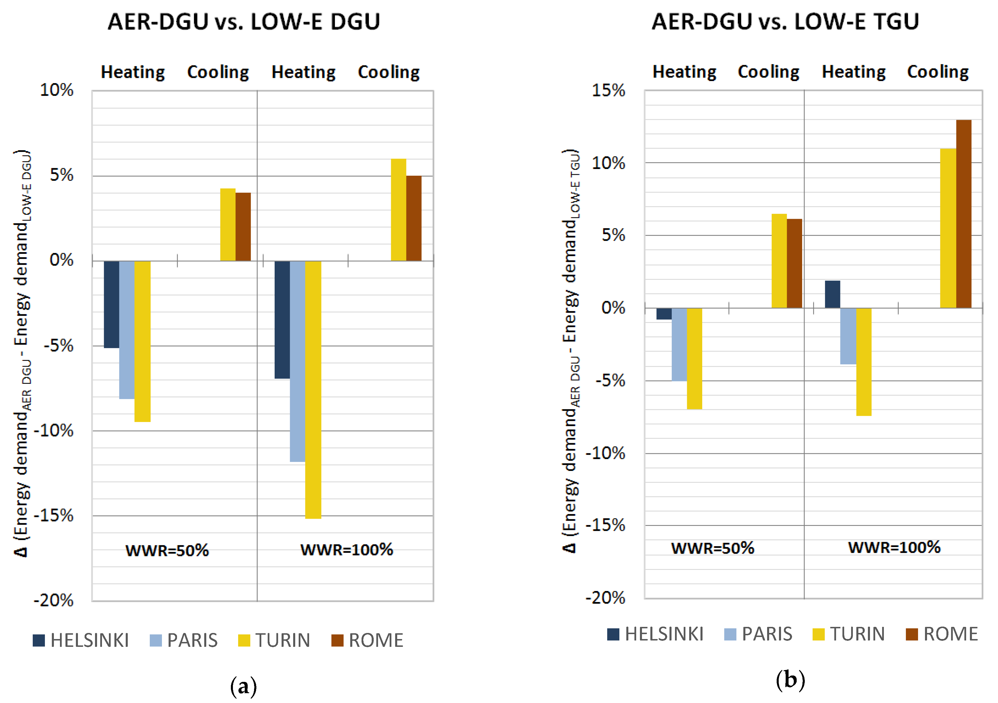
3.2. Simulation Results and Comparison with Conventional Glazing Solutions

The innovative solution (here referred as AER-DGU) was compared with commercially available glazing systems, which were considered in this study as benchmarks:
  • an argon (90%) filled double glazing embodying a low-e (Magnetron Sputter Vacuum Deposition) coating (here referred as LOW-E DGU);
  • an argon (90%) filled triple glazing embodying two low-e (Magnetron Sputter Vacuum Deposition) coatings (here referred as LOW-E TGU).
Their main features and energy performance parameters are reported in Table 5.
As a first comparison, it can be observed that the U-value of the aerogel window is comparable to that of the low-e glazing (aerogel system U-value 10% lower than LOW-E-DGU), while the LOW-E-TGU U-value is 30% lower than the one of the aerogel sample. Nevertheless, while the aerogel and the LOW-E-DGU glazing have about the same thickness (24–26 mm), the LOW-E-TGU thickness is 10 mm more (36 mm).
The g-value of the aerogel sample (0.70) is higher than both the LOW-E systems: +0.15 with respect to DGU and + 0.26 with respect to TGU.
The light transmittance τv of the aerogel glazing unit is 0.69; it is comparable to the one of a triple glazing window (LOW-E-TGU shows a value of 0.66). It is lower than the τv of the LOW-E-DGU, equal to 0.76 (-0.07). The lighting behavior of the monolithic solution is intermediate between the one of the conventional solutions chosen for the comparison, but the g-value is significantly higher and the thickness lower, especially when compared to the triple glazing unit.
Simulations were carried out in order to show the influence of the glazing typology on building energy performance: ideal energy use was calculated to meet the zone loads, which means 100% efficiency for heating, cooling, and ventilation systems. The relative performance of the aerogel glazing was assessed by looking at the differences in the annual energy demand for heating, cooling, and lighting. Table 6 and Table 7 (for the window-to-wall ratio WWR1 = 50 % and WWR2 = 100 %, respectively) show the energy loads (by considering the 2nd floor of the building) for the three typologies of glazing units at the four considered climate conditions.
In winter, aerogel glazing outperforms conventional solutions in all the examined climate conditions: when compared to low-e double glazing (Figure 4) and to low-e triple glazing (WWR1), it guarantees heating load reduction of about 5% and 1%, respectively, in Helsinki, of about 9% and 7%, respectively, in Turin, and of about 8% and 5 %, respectively, in Paris. For hot climate (Rome), the heating energy demands are very low for all the glazing systems.
When considering a higher window-to-wall ratio (WWR2 = 100%) the benefits slightly increase (Figure 4): for moderate climate conditions (Turin), a reduction of 15% is obtained with respect to low-e DGU, whereas it is about 7% and 12% lower in Helsinki and Paris, respectively. Results are consistent with U and g values of the windows: the heating energy savings due to the innovative solution are higher in Turin, characterized by higher solar radiation, especially in winter time. The higher solar factor increases, indeed, the heat gain from aerogel windows. At the same time, the high value of the solar factor for the aerogel glazing increases the energy demand for cooling in moderate and hot climates: when compared to low-e double glazing and to low-e triple glazing (WWR1), it is 4% and 7% higher, respectively, in Turin, 11% for both in Paris, and about 4% and 6 % in Rome. The cooling energy demand increase is higher when considering a higher window-to-wall ratio (WWR2 = 100%, Figure 4). The energy demand for artificial lighting is quite similar for all the windows (Table 6 and Table 7); the daylight illuminance on the working plane is higher than the recommended value (500 lux [30]) for most of the daylight hours for the three glazing systems during the year, also due to the high window-to-wall ratios of the investigated building. The energy demand for lighting is hence driven by energy uses in non-daylight hours during working time, making the impact of different lighting transmittance of the selected samples close to negligible.
Based on these results, the glazing systems with monolithic aerogel could be considered a good solution for space heating demand, especially in moderate climates (namely, Turin). The energy savings could increase when considering higher aerogel pane thicknesses, which can allow a lower U-value and a higher reduction in heating loads. However, due to the energy demand increasing for cooling, the annual energy consumptions with monolithic aerogel solutions could be quite lower when compared to conventional double glazing systems, depending on the HVAC systems and their efficiency.

4. Conclusions

The monolithic aerogel is going to become an interesting solution for building transparent envelopes, thanks to a recent Rapid Super-Critical Extraction technique (Union RSCE) developed at Union College, Schenectady (New York, NY, USA). It is possible to fabricate panes by means of a process lasting hours rather than days. A sample of a glazing system incorporating a monolithic aerogel between two glass panes was thermally characterized and results, together with the optical properties investigated by the authors in a previous work [17], were used to simulate the energy performance of a commercial building when comparing the proposed solution with conventional ones.
The thermal resistance of the sample, consisting of a 15-mm-thick aerogel pane sandwiched between two clear float glasses with a thickness of 4.7 mm each, varies in the 0.72–0.74 m2K/W range, with a corresponding thermal transmittance of about 1.1 W/m2K. The thermal conductivity estimated for the monolithic aerogel pane is 0.020–0.021 W/mK at about 38––41 °C. When reported at 10 °C, following the procedure suggested by the Standard ISO 10456 [20], the thermal conductivity of the only monolithic pane is in the 0.018–0.019 W/mK range. A corresponding U-value of the glazing system of 0.99–1.00 W/m2K is found. Due to the size limitation of the sample, the g-value could not be measured directly and a simplified method suggested by EN 410 and ISO 9050 was used. The window package was modelled as a three-layer system composed of two glazing panes and an inside aerogel layer, separated by two very thin air gaps; this is another limitation of the modelling phase. An estimated value of g equal to 0.70 was found.
Moreover, a dynamic simulation model was used for calculating the annual energy demand for heating, cooling, and lighting of an office building with large strip windows in the east and west wall. Window-to-wall ratios of 50% and 100% were considered in different climate conditions. Results were compared with conventional solutions, such as double and triple glazing units.
Considering a non-residential building with the features described in this manuscript, it was observed that aerogel glazing outperforms conventional solutions in all the climate conditions for space heating, especially in moderate ones, with a maximum energy demand reduction of about 10% with respect to double glazing units. The benefits increase to 15% when increasing the window-to-wall ratio. On the other hand, the high value of the solar factor increases the energy demand for cooling (about 11% in moderate climates), becoming worse when increasing the window-to-wall ratio. The energy demand for artificial lighting is quite similar for all the investigated solutions, with the aerogel window characterized by a good light transmission.
In conclusion, the annual energy demand with a monolithic aerogel solution is quite lower when compared to conventional double glazing systems in cold and moderate climates. The performance is comparable with the one of a triple glazing unit with argon, but it is characterized by a higher thickness (36 mm instead of about 24 mm) and weight and the choice of the best solution would take into account all aspects, including the geometry of the building, the location, the internal loads, and the costs.
Future works will be carried out in order to characterize this new material; accelerated aging tests will allow to evaluate the performance of the monolithic aerogel pane over time. Other accurate dynamic simulations will be carried out in order to examine more feasible cases, by considering the influence of the frame in real applications.
Moreover, the high hopes for the future fabrication of these panes are related to the shape of the samples and their dimensions; more regular monolithic aerogel panes with larger surfaces are in development. Their performance could be analyzed by means of in-situ measurements both at pilot and real scales.

Author Contributions

All the authors contributed equally to the conception, the design, the experimental campaigns, the simulation analysis and the writing of this paper.

Funding

This research received no external funding.

Acknowledgments

The authors gratefully acknowledge the Union College (Schenectady–NY) that fabricated the sample for the scientific investigations of this paper. The authors also thank the financial support of ENEA to this research through the project entitled “Progetto D.1 Tecnologie per costruire gli edifici del futuro” within the scope of “Accordo di Programma MISE_ENEA 2015-2017 Ricerca di Sistema Elettrico–PAR 2016 2” funding programme. The authors thank Dr. Francesca Merli for her collaboration during the simulations.

Conflicts of Interest

The authors declare no conflict of interest.

References

  1. Liang, Y.; Wu, H.; Huang, G.; Yang, J.; Wang, H. Thermal performance and service life of vacuum insulation panels with aerogel composite cores. Energy Build. 2017, 154, 606–617. [Google Scholar] [CrossRef]
  2. Jelle, B.P. Traditional, state-of-the-art and future thermal building insulation materials and solutions—Properties, requirements and possibilities. Energy Build. 2011, 43, 2549–2563. [Google Scholar] [CrossRef] [Green Version]
  3. Moretti, E.; Belloni, E.; Merli, F.; Zinzi, M.; Buratti, C. Laboratory and pilot scale characterization of granular aerogel glazing systems. Energy Build. 2019, 202, 109349. [Google Scholar] [CrossRef]
  4. Baetens, R.; Jelle, B.P.; Gustavsen, A. Aerogel insulation for building applications: A state-of-the-art review. Energy Build. 2011, 43, 761–769. [Google Scholar] [CrossRef] [Green Version]
  5. Jensen, K.I.; Schultz, J.M.; Kristiansen, F.H. Development of windows based on highly insulating aerogel glazings. J. Non-Cryst. Solids 2004, 350, 351–357. [Google Scholar] [CrossRef]
  6. Carroll, M.K.; Anderson, A.M.; Gorka, C.A. preparing silica aerogel monoliths via a rapid supercritical extraction method. J. Vis. Exp. 2014, 84, e51421. [Google Scholar] [CrossRef] [Green Version]
  7. Bhuiya, M.M.H.; Anderson, A.M.; Carroll, M.K.; Bruno, B.A.; Ventrella, J.L.; Silberman, B.; Keramati, B. Preparation of monolithic silica aerogel for fenestration applications: Scaling up, reducing cycle time, and improving performance. Ind. Eng. Chem. Res. 2016, 55, 6971–6981. [Google Scholar] [CrossRef]
  8. Guoqing, Z.; Jun, S.; Xiaoqing, W.; Xingyuan, N.; Zhihua, Z.; Jichao, W.; Guangwu, L. Preparation and characterization of monolithic alumina aerogels. J. Non-Cryst. Solids 2011, 357, 2903–2906. [Google Scholar]
  9. Duer, K.; Svendsen, S. Monolithic silica aerogel in superinsulating glazings. Sol. Energy 1998, 63, 259–267. [Google Scholar] [CrossRef]
  10. Wong, J.C.H.; Kaymak, H.; Brunner, S.; Koebel, M.M. Mechanical properties of monolithic silica aerogels made from polyethoxydisiloxanes. Microporous Mesoporous Mater. 2014, 183, 23–29. [Google Scholar] [CrossRef]
  11. Cai, J.; Liu, S.; Feng, J.; Kimura, S.; Wada, M.; Kuga, S.; Zhang, L. Cellulose-silica nanocomposite aerogels by in situ formation of silica in cellulose gel. Angew. Chem. Int. Ed. 2012, 51, 2076–2079. [Google Scholar] [CrossRef] [PubMed]
  12. Buratti, C.; Moretti, E. Experimental performance evaluation of aerogel glazing systems. Appl. Energ. 2012, 97, 430–437. [Google Scholar] [CrossRef]
  13. Schultz, J.M.; Jensen, K.I.; Kristiansen, F.H. Super insulating aerogel glazing. Solar Energy Mater. Sol. Cells 2005, 89, 275–285. [Google Scholar] [CrossRef]
  14. Buratti, C.; Moretti, E.; Belloni, E. Nanogel windows for energy building efficiency. In Nano and Biotech Based Materials for Energy Building Efficiency; Torgal, F.P., Buratti, C., Kalaiselvam, S., Granqvist, C.G., Ivanov, V., Eds.; Springer International Publishing: Cham, Switzerland, 2016; pp. 41–69. [Google Scholar]
  15. Mujeebu, M.A.; Ashraf, N.; Alsuwayigh, A.H. Effect of nano vacuum insulation panel and nanogel glazing on the energy performance of office building. Appl. Energy 2016, 173, 141–151. [Google Scholar] [CrossRef]
  16. Ihara, T.; Gao, T.; Grynning, S.; Jelle, B.P.; Gustavsen, A. Aerogel granulate glazing facades and their application potential from an energy saving perspective. Appl. Energy 2015, 142, 179–191. [Google Scholar] [CrossRef]
  17. Zinzi, M.; Rossi, G.; Anderson, A.M.; Carroll, M.K.; Moretti, E.; Buratti, C. Optical and visual experimental characterization of a glazing system with monolithic silica aerogel. Sol. Energy 2019, 183, 30–39. [Google Scholar] [CrossRef]
  18. Buratti, C.; Belloni, E.; Lunghi, L.; Barbanera, M. Thermal conductivity measurements by means of a new ‘Small Hot-Box’ apparatus: Manufacturing, calibration and preliminary experimental tests on different materials. Int. J. Thermophys. 2016, 37, 47. [Google Scholar] [CrossRef]
  19. JCGM/WG 1. Evaluation of Measurement Data–GUM, Guide to the Expression of Uncertainty in Measurement; Technical Report JCGM 100:2008; ISO: Geneva, Switzerland, 2008. [Google Scholar]
  20. International Organization for Standardization. Building Materials and Products—Hygrothermal Properties—Tabulated Design Values and Producers for Determining Declared and Design Thermal Values; Technical Report ISO/FDIS 10456:2007(E); ISO: Geneva, Switzerland, 2007. [Google Scholar]
  21. Buratti, C.; Merli, F.; Moretti, E. Aerogel-based materials for building applications: Influence of granule size on thermal and acoustic performance. Energy Build. 2017, 152, 472–482. [Google Scholar] [CrossRef]
  22. Gao, T.; Jelle, B.P.; Ihara, T.; Gustavsen, A. Insulating glazing units with silica aerogel granules: The impact of particle size. Appl. Energy 2014, 128, 27–34. [Google Scholar] [CrossRef]
  23. CEN. Glass in Building—Determination of Luminous and Solar Characteristics of Glazing; Technical Report BS EN 410:1998; European Committee for Standardization: Brussels, Belgium, 2011. [Google Scholar]
  24. International Organization for Standardization. Glass in Building—Determination of Light Transmittance, Solar Direct Transmittance, Total Solar Energy Transmittance, Ultraviolet Transmittance and Related Glazing Factors; Technical Report ISO 9050:2003; ISO: Geneva, Switzerland, 2013. [Google Scholar]
  25. CEN. Light and Lighting—Lighting of Work Places—Part 1: Indoor Work Places; Technical Report BS EN 12464-1:2011; European Committee for Standardization: Brussels, Belgium, 2011. [Google Scholar]
  26. Goia, F.; Haase, M.; Perino, M. Optimizing the configuration of a facade module for office buildings by means of integrated thermal and lighting simulations in a total energy perspective. Appl. Energy 2013, 108, 515–527. [Google Scholar] [CrossRef] [Green Version]
  27. Ihara, T.; Gustavsen, A.; Jelle, B.P. Effect of facade components on energy efficiency in office buildings. Appl. Energy 2015, 158, 422–432. [Google Scholar] [CrossRef]
  28. WINDOW; version 7.4; Lawrence Berkeley National Laboratory, University of California: Berkeley, CA, USA, 2016. Available online: https://windows.lbl.gov/software/window (accessed on 10 January 2019).
  29. Optics; version 5.0; Lawrence Berkeley National Laboratory, University of California: Berkeley, CA, USA, 2013. Available online: https://windows.lbl.gov/software/optics (accessed on 10 January 2019).
Figure 1. Glazing system with monolithic silica aerogel: investigated sample (supplied by Union College, Schenectady, NY, USA).
Applsci 09 05473 g001
Figure 2. (a) Small Hot Box apparatus and (b) particular of the monolithic sample with the probes’ position (T = thermo-resistances, TF = thermal flux meter).
Applsci 09 05473 g002
Figure 3. Model of the buildings: Window-to-Wall Ratio (WWR1) (a) and WWR2 (b).
Applsci 09 05473 g003
Figure 4. Percentage variation of heating and cooling demand of aerogel glazing system with respect to low-e double (LOW-E DGU) (a) and triple (LOW-E TGU) (b) glazing units, in different climate conditions (negative values are savings, positive ones are penalties for the aerogel solution).
Applsci 09 05473 g004
Table 1. The investigated building: features of the opaque envelope components.
Building ElementsThickness [m]Thermal Transmittance [W/m2K]
External wall0.240.57
Internal wall0.113.41
Ground floor (including gravel layer)0.990.48
Roof0.520.32
Floor between storeys0.500.52
Table 2. Simulation hypothesis: internal loads, operating periods of heating and cooling system, infiltration rate.
Internal LoadsSchedule
Lighting peak power (500 lux [30], fully dimmable lamps)7 W/m28:00 a.m. to 6:00 p.m.
weekdays
People0.05 people/m2
Equipment7 W/m2
Operating periods of heating and cooling system
LocationHeating (20 °C)Cooling (26 °C)
Helsinki01/01–12/3105/01–09/048:00 a.m. to 6:00 p.m.
weekdays
Paris10/15–04/3005/01–10/14
Turin10/15–04/1504/16–10/14
Rome11/01–04/1504/16–10/14
Infiltration rate
Whole building0.3 vol/h12:00 p.m. to 08:00 a.m.
6:00 p.m. to 12:00 p.m.
All days
0.6 vol/h08:00 a.m. to 6:00 p.m.
Table 3. Thermal properties of the aerogel glazing sample measured with the thermal flux meter methodology in the Small Hoot Box apparatus.
ΔTair
[°C]
Ts Mean
[°C]
ΔTs
[°C]
Heat Flux Φ
[W/m2]
Thermal Resistance R
[m2K/W]
Relative Uncert.
[%]
U
[W/m2K]
λ Monolit. Aerogel
[W/mK]
U at 10 °C
[W/m2K]
λ Monolit. Aerogel at 10 °C
[W/mK]
Test 1
(TH = 45 °C)
18.337.716.822.70.743.51.0990.02040.9970.0182
Test 2
(TH = 50 °C)
22.940.921.730.10.726.21.1240.02091.0090.0185
Test 3
(TH = 50 °C)
22.740.721.029.10.722.61.1240.02091.0100.0185
Test 4
(TH = 45 °C)
18.937.716.522.50.742.91.0990.02040.9970.0182
Table 4. Solar properties of the aerogel DGU.
τe [-]αe [-]qi [-]g [-]
0.62 [18]0.19 [18]0.080.70
Table 5. Constructive, thermal, and optical features of the investigated glazing systems.
GlazingDescriptionThickness [mm]τv
[-]
g
[-]
U
[W/m2K]
AER- DGUFloat clear glass (4.7 mm),
monolithic aerogel (15 mm),
float clear glass (4.7 mm)
24.40.690.701.0
LOW-E DGUFloat clear glass (6 mm),
Air (10%) and Argon (90%) (16 mm),
Low-e float clear glass (4 mm)
260.760.551.1
LOW-E TGULow-e float clear glass (4 mm), Air (10%) and Argon (90%) (12 mm), float clear glass (4 mm), Air (10%) and Argon (90%) (12 mm), Low-e float clear glass (4 mm)360.660.440.7
Table 6. Heating, cooling, and lighting energy demand for the investigated glazing systems when considering WWR1 (50%).
GlazingHeating Energy Demand
[kWh/m2]
Cooling Energy Demand
[kWh/m2]
Lighting Energy Use
[kWhe/m2]
LOW-E DGU52.60.48.6
HELSINKILOW-E TGU50.30.49.1
AER-DGU49.90.58.9
LOW-E DGU14.89.47.5
TURINLOW-E TGU14.49.28
AER-DGU13.49.87.7
LOW-E DGU18.52.87.8
PARISLOW-E TGU17.92.88.3
AER-DGU173.18.1
LOW-E DGU2.914.97.2
ROMELOW-E TGU3.114.67.6
AER-DGU2.215.57.3
Table 7. Heating, cooling, and lighting energy demand for the investigated glazing systems when considering WWR2 (100%).
GlazingHeating Energy Demand
[kWh/m2]
Cooling Energy Demand
[kWh/m2]
Lighting Energy Use
[kWhe/m2]
LOW-E DGU51.90.77.9
HELSINKILOW-E TGU47.40.68.2
AER-DGU48.30.88
LOW-E DGU13.210.26.8
TURINLOW-E TGU12.19.77
AER-DGU11.210.86.9
LOW-E DGU16.93.57
PARISLOW-E TGU15.53.27.2
AER-DGU14.93.97.1
LOW-E DGU1.716.96.5
ROMELOW-E TGU1.715.86.7
AER-DGU1.117.86.6

