Article

Decentralized Bioinspired Non-Discrete Model for Autonomous Swarm Aggregation Dynamics

by
Panagiotis Oikonomou
1,* and
Stylianos Pappas
2
1
Department of Engineering and Natural Sciences, New York University Abu Dhabi, PO Box 129188, UAE
2
Institute of Communication and Computer Systems (ICCS), School of Electrical and Computer Engineering (ECE), National Technical University of Athens (NTUA), 9 Iroon Polytechniou Str., 15773 Zografou, Greece
*
Author to whom correspondence should be addressed.
Appl. Sci. 2020, 10(3), 1067; https://doi.org/10.3390/app10031067
Submission received: 16 January 2020 / Revised: 29 January 2020 / Accepted: 1 February 2020 / Published: 5 February 2020

Abstract

:
In this paper a microscopic, non-discrete, mathematical model based on stigmergy for predicting the nodal aggregation dynamics of decentralized, autonomous robotic swarms is proposed. The model departs from conventional applications of stigmergy in bioinspired path-finding optimization, serving as a dynamic aggregation algorithm for nodes with limited or no ability to perform discrete logical operations, aiding in agent miniaturization. Time-continuous simulations were developed and carried out where nodal aggregation efficiency was evaluated using the following metrics: time to aggregation equilibrium, agent spatial distribution within aggregate (including average inter-nodal distance, center of mass of aggregate deviation from target), and deviation from target agent number. The system was optimized using cost minimization of the above factors through generating a random set of cost datapoints with varying initial conditions (number of aggregates, agents, field dimensions, and other specific agent parameters) where the best-fit scalar field was obtained using a random forest ensemble learning strategy and polynomial regression. The scalar cost field global minimum was obtained through basin-hopping with L-BFGS-B local minimization on the scalar fields obtained through both methods. The proposed optimized model describes the physical properties that non-digital agents must possess so that the proposed aggregation behavior emerges, in order to avoid discrete state algorithms aiming towards developing agents independent of digital components aiding to their miniaturization.

1. Introduction

Biological behaviors have been recently serving as the basis for multiple different algorithms designed for multi-agent robotic systems coordination. This field is referred to as Swarm Robotics (SR) where numerous simply constructed physical robots (nodes/agents) are controlled such that certain behaviors emerge [1]. Swarm agents are usually relatively small in scale and low cost, ideally deprived of the ability to perform real time complicated calculations and attain global information about their environment [2,3]. Their large number in a small area is what gives rise in a more complicated ability to perform an action coined as Swarm Intelligence [1,2,3].
Robotic Swarms can be categorized to homogeneous and heterogeneous based on the differences between the type of task that the individual nodes are able to perform [4]. Specifically, swarms where robots of different design or functionality coexist are coined as heterogeneous [5]. SR systems range from areal heterogeneous surveillance swarms designed for wide coverage tracking and scouting operations [6], to micro-scale magnetic homogeneous aggregation swarms controlled via external magnetic fields [7].
There is a variety of mathematical and algorithmic problems related to what type of task an SR system is designed to perform. The problems or research areas were identified by Levent Bayındır in his “Review of swarm robotics tasks” to be the following: aggregation, flocking, foraging, object clustering and sorting, navigation, path formation, deployment, collaborative manipulation and task allocation [8]. While individual SR systems may fall in multiple of the aforementioned areas, in general there are certain traits shared between systems in the same category such as specific algorithms and architecture [8]. This paper specifically deals with the development of algorithms for SR systems that are designed to tackle aggregation related tasks. Specifically, aggregation describes the set of tasks where gathering a number of agents in a single location with a particular distribution is desired [8].
Aggregation, in particular, is commonly observed in nature with biological systems such as bee swarms [9,10,11] and cockroach pools under light spots [12,13,14]. In such systems, aggregation or de-aggregation is a result of external stimulation such as the presence or absence of food sources or, more notably, predation [15]. In detailed studies carried out on fish schools, where predation signals were artificially induced under lab conditions through chemical [16] or bionic [17] stimuli, aggregation was noted as instinctive behavior present even in newborns. The dissemination of an aggregate was a result of either the loss of predator or food signals [16,17].
A prominent method to tackle this problem is probabilistic aggregation, a strategy where agents “walk randomly” among the aggregates and the stopping probability depends on the nodes sensed in an aggregate [8,12]. This algorithm is usually implemented with finite state machines with varying possible states [12,18]. Other methods include environmental mediation [8] where while nodes can perform really simple or almost no computations, the environment is providing with multiple control information to form their aggregation [19,20].
In numerous reviews [2,4,5,8,20] a common requirement for the widespread deployment of swarm robotics for practical applications is identified to be miniaturization. Due to current hardware limitations, miniaturization of digital systems (to the micro or even nano scale) is forbiddingly hard. As a result, this paper provides an aggregation model based on environment mediation and probabilistic aggregation that achieves the relaxation of the finite state machine implementation of the previously mentioned approaches. This way, the aggregation model can be implemented on agents with no digital processing power. Eliminating digital calculation, allows for agent independence from digital components that cannot be functionally miniaturized to a micro or nano scale, and hence the potential for development of intelligent analog micro and nanoswarms.

2. Model Presentation
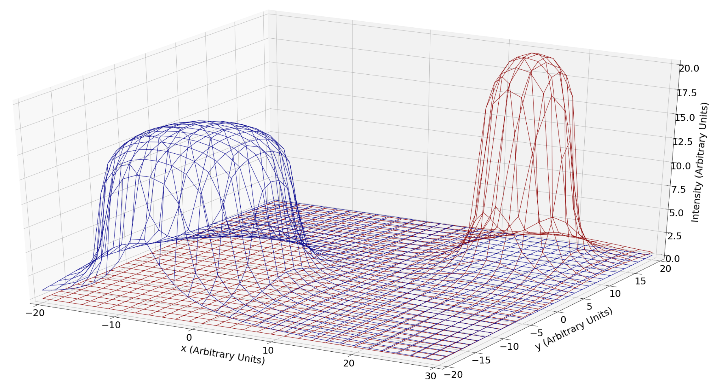
2.1. Stigmergy

The aggregation model proposed is based on stigmergy, a method of indirect environment mediated communication [21] that is primarily found in biological aggregation systems such as ant colonies [22,23,24]. According to Gordon et al. ants solve the task of optimal path-finding and resource allocation by secreting pheromones forming trails that other ants can sense and deduce not only the trajectory but also the number and type of ants following a particular trail [25,26].
This model of ant-stigmergy is traditionally used for the purposes of optimization [27,28,29]; however in this case stigmergy is mostly considered to be the ability of the environment to indicate the number and location of the desired agents of an aggregate, rather than used for foraging.
The model considers the interactions between tasks, the representation of an aggregate including its location and desired number of agents, and agent, the basic unit of the overall swarm. These terms are further defined below.

2.2. Task

An enclosed area ( A T ) where a specific number of agents ( n T ) needs to aggregate in order to perform a particular operation is defined as a task (T). Each swarm of agents can accommodate for multiple tasks to be carried out simultaneously where an appropriately sized collection of agents will aggregate with a particular distribution over the task area with center of mass at point p T . For simplification purposes in simulation and optimization, in this paper we constrain the task definition to be 2D circles with radius R T in a cartesian plane, where the coordinates of the center are given by a point p T , and the nodes are uniformly distributed.
A fundamental property of any task is a stigmergic indicator that penetrates the entirety of the field. The abstraction in the indicator type is maintained for the purposes of describing the model, in an application the indicator can be anything that has an inverse square intensity relationship with distance from the source, such as electromagnetic waves of different wavelengths for different tasks, or an intensity relationship close to that, such as chemical concentration of different solutes for different tasks in a global solvent. In this paper, we model the indicator for a point task (i.e., R T 0 ) as having an inverse square intensity relationship I T with distance of the form:
I T ( r ) P 4 π | p T r | 2 + δ
where δ 0 to avoid division by 0, P R is representing the power of the indicator that each node can emit, and r is any position in the coordinate system that the task exists. Equation (2) represents the true intensity of a task at any point r by taking the volume integral over the task area.
I T ( r ) = 1 A T A T n T P 4 π | r x | 2 + δ 2 d A T
A graph of the solution for 1 task centered at the origin with an arbitrary radius and power is seen in Figure 1.
Providing different types of indicators for each task allows for the agent’s distinction of the individual tasks in their superposition. Figure 2 illustrates the superposition of two tasks in a 2D field. It is evident that the indicator is detectable in the entirety of the field, with a sharp increase near the edge of the circular task. The xy axes are arbitrary positional axes, while the z-axis represents the intensity at any point of the field in some common arbitrary units. The different type of indicators (represented by different colors) is aiding in the distinction of the two individual tasks.

2.3. Node

A node is the smallest individual unit agent of a swarm. Each node initially selects a random task t as its target. In essence each node must have the property to follow the indicator increase of its target task, as well as switch target based on the type of indicator tied to a particular task. Specifically, the velocity of node n ( v n ) in a swarm S should be in the general direction of the steepest indicator ascent. For the ideal case this is sown in (3).
v ^ n I t ( r n ) | I t ( r n ) |
where r n is the vector of the position of node n in the described coordinate system. As a result, the direction of motion of each node is defined by the positional rate of change in the indicator intensity. This type of directed motion that maximizes an indicator is in fact evident in multiple non-digital systems such as magnetic aggregation of filings [7], protein targeting across chemical gradients, etc.
Assuming constant speed, this behavior is sufficient to solve the aggregation problem at the center of mass of the tasks. It fails, however, to solve the problem of the particular distribution of nodes within each task. As defined earlier, a task emits an indicator whose intensity is proportional to the density of nodes at this point. In other words, if each node is able to produce an inverse square indicator ( I n ) as in (1), then the intensity of the average superposition of all the desired nodes over the task’s area would be equal to the intensity function ( I t ) of that task. Therefore, for the nodes to conform to the desired distribution inside the aggregate, they need only to match the task’s indicator intensity profile. As a result, if a node is targeted to an aggregate where significantly more than the ideal number of nodes are present, then the total node indicator superposition will be higher than the ideal one emitted by the task, therefore that node must move away. If that keeps persisting, then the node should switch task. In the inverse case, where the density of nodes in an aggregate is less than desired, the total node indicator superposition will be lower than the ideal, thus the node must stay.
To mathematically formulate the above logic, a confidence function ( C T n ( r , t ) ) is defined in (4). Specifically, the function C T n is a value that indicates how good is position r for a node n targeted to task T to stay in. A really high confidence, implies that the node should stop moving and stay in that position, while a low confidence can signal a change in target task.
C T n ( r , t ) t Δ t t I T ( r ) ( I T ( r ) D T n ( r ) ) d t
where D T n ( r ) , defined in (5), is the detected intensity superposition of all the nodes that emit the signal related to task T at position r . Δ t is also a number in seconds that indicates the time window that the integral is taken.
D T n ( r ) i N T I i ( r )
where N T is the set of all nodes that are targeted to task T.
The confidence function is therefore defined for each node to be proportional to the difference between the ideal and detected indicator intensity for a particular task, as well as the intensity of the task itself. As seen in Figure 3 the confidence function is designed such that intensity from nodes that are inside the task contribute more than the ones that are outside. In Figure 3a the nodes performing the task are emitting an indicator shown in red, while the indicator emitted from the task is shown in black. Ideally, the node will be able to skip over the first nodes and achieve engagement confidence shortly after. In Figure 3b simulated Confidence integral based on input data depicted in Figure 3a. The confidence thresholds C e and C d are shown in green and red, respectively. It is possible to see that the confidence value surpasses the C e value, allowing for the node to engage in the studied task.
While short-term exposure to confidence above or below optimal values is to be neglected, long-term exposure implies a change in the target task. As a result, two limits are introduced that when reached the node will either change the target task, or ideally reduce its speed to zero. The Engagement Confidence ( C e ) limit (indicated in green in Figure 3b) is the value of confidence that when reached the node will ideally set its velocity to zero. The Disengagement Confidence ( C d ) limit (indicated in red in Figure 3b) is the value of confidence where the node will change its target task, as it being there disrupts the ideal aggregate distribution.
Furthermore, the speed of the node should be confidence determined. In actuality, the lower the confidence the higher the speed of the node should be, until it eventually reaches zero when the aggregation confidence is attained. To mathematically formulate this desired behavior a sigmoid function (6) is used to define the velocity amplitude of any node n at position r and time t .
| v n ( r , t ) | v m a x 1 + e x p ( C T n ( r , t ) C e )
where v m a x is an arbitrary scaling constant, and T is the target task of node n.
Finally, it was demonstrated—see simulation section—that a set of agents that satisfy the aforementioned conditions will qualitatively emerge the desired aggregation profile of multiple location centers and particular distribution.

3. Simulation Methodology

3.1. Assumptions

Digital, pseudo time continuous, multithreaded simulations were designed and carried out to test the aggregation properties of the aforementioned mathematical model. Nodal aggregation simulations were carried under the assumption of relatively large swarm size (>100 nodes) in a small field ( 5 × 5 length units square; average radius of task is 1 length unit for comparison). Pseudo time continuity was achieved by discretization of time in small intervals with d t < 0.1 time units (s). Distance and time units were kept abstract.
Physical nodes were modeled as 0-width points due to the small volume and large number assumptions, implying that collisions between them are unlikely to interfere with the general swarm motion significantly. The nodes were designed to detect and emit an abstract indicator as described in the previous section. Standard Newtonian kinematics were used for movement and collision detection with the exception being that the velocity of each node was given by (7).
v n = | v n | v ^ n = v m a x 1 + e x p ( C T n ( r , t ) C e ) I t ( r n ) | I t ( r n ) |
A further estimation, based on a single variate active rolling average method, was used in calculating the confidence rolling time integral for each node seen in (4) to speed up processing and conserve memory space. Assuming a time discrete sampled continuous signal x with measurements x i and sampling rate f, the rolling average with a window of N measurements over a time period Δ t is given by (8).
x ¯ = 1 N i = 0 N x i = 1 f Δ t i = 0 f Δ t x i
We can take the discrete integral approximation to be (9).
t t + Δ t x d t i = t / d t ( t + Δ t ) / d t x i d t
Assuming that the integral step is equal to the sampling period ( d t = 1 f ), combining (8) and (9) we get (10).
t t + Δ t x d t i = f t f t + f Δ t x i f = x ¯ Δ t
Therefore, it is possible to predict a mean with a single variable by using a modified moving average (MMA) as described in Nayak, 2015, A Naïve SVM-KNN-based stock market trend reversal analysis for Indian benchmark indices and shown in (11)
x ¯ x ¯ o l d ( N 1 ) + x n e w N

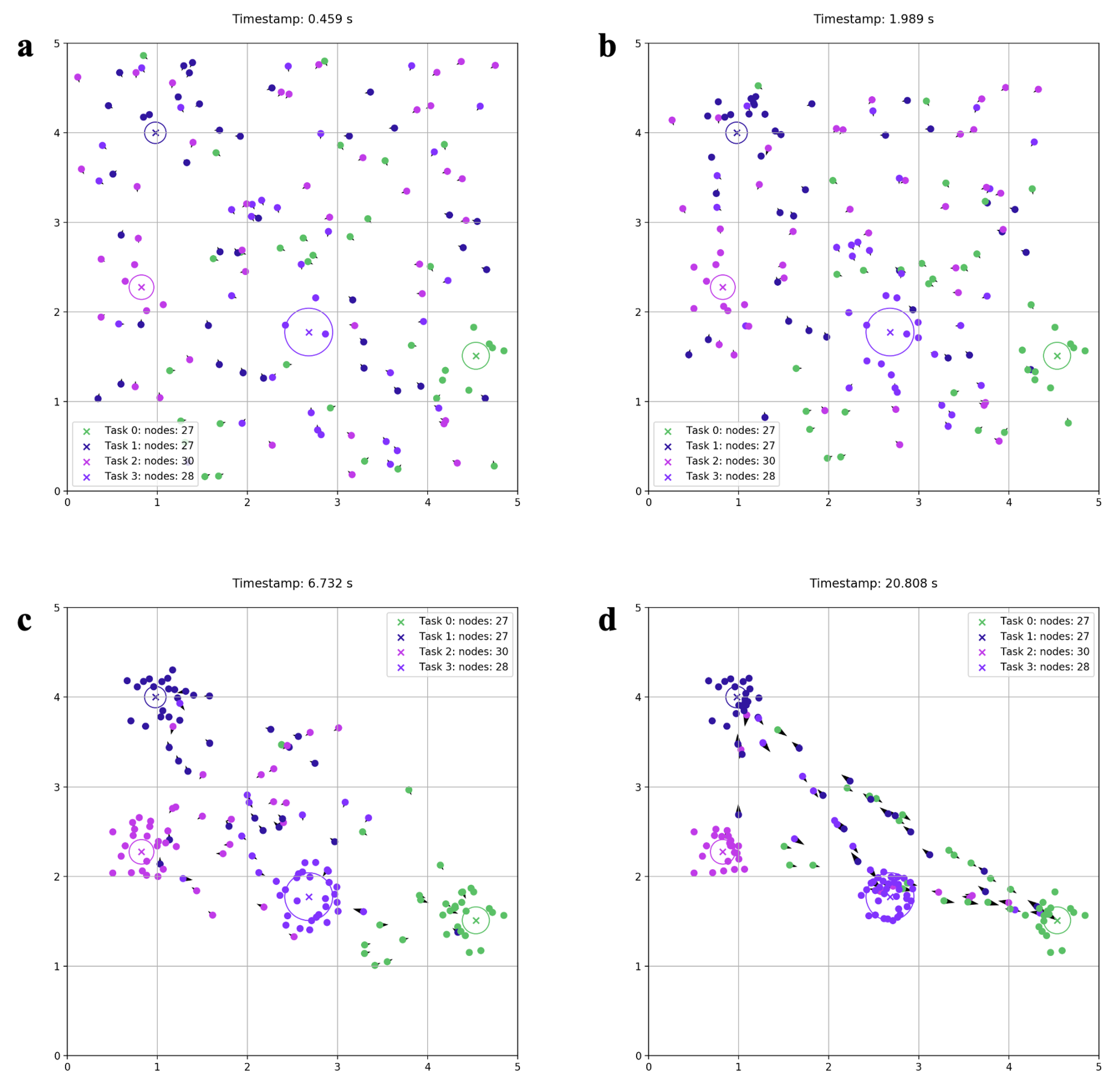
3.2. Qualitative Simulation Results

Figure 4 and Figure 5 show processions over time of two different simulated scenarios where nodal aggregation was achieved. Each task is associated with a random color seen in the legend. The color of each node represents its target task. The small black arrow of each node indicates the direction and magnitude of the velocity of said node. The nodes, over time, seem to aggregate at the desired spots. Equilibrium seems to have been achieved at Figure 4c and Figure 5d respectively, as there is no significant change in the number of nodes in the tasks. Furthermore, wandering nodes targeted to tasks but not stopping in them are observed after the equilibrium is achieved. Especially in Figure 5b these nodes are moving in strict linear paths connecting each task with a random number of nodes at each time and segment. Coverage of the task area seems to increase with the number of nodes needed for each task.
From these simulations it was shown that, qualitatively, it is ideal for the swarm to have a larger number of nodes than the total number of nodes required for a task. That is because once equilibrium is achieved (change in number of nodes over time in a task is minimum) the remaining nodes will travel randomly among aggregates without engaging in any. This is a significant feature, as in case of malfunction in several nodes, the system will naturally replace them over a short time period, as there are always nodes traveling between the aggregates.
Specifically, as seen more clearly in Figure 5d, the remaining of the nodes along with the tasks form the vertices and segments of a dynamic graph that will allow for the reallocation of the inactive agents in case of removal of several working agents in the aggregate. This behavior renders the swarm “self-healing,” however, it is of essence that there is no identifiable discrete state change between the inactive and active mode, their stationarity or movement is a complete analog result. Something that allows them to reorient within the aggregate dynamically in case a better (higher confidence) position is discovered.
It is important to mention that Figure 4 and Figure 5 illustrate the outcome of the nonoptimized aggregation model.

4. Aggregation Evaluation Metrics

At this point a complete model of the swarm’s aggregation properties has been proposed where its performance is dependent on several free variables identified in previous sections. It is now possible to construct a vector θ to represent the condition state of the system in a real higher-dimensional vector space. Theta is defined in (12)
θ P v m a x Δ t C e C d
To quantitatively evaluate the aggregation capabilities of the swarm in each simulated scenario 4 metrics were introduced based on the qualitative synopsis of the metrics for estimating robot aggregation efficiency presented by Shlyakhov in [30]. Shlyakhov [30] provided several methods to test aggregation efficiency, of those the 4 following metrics were derived:
  • The center of mass of the nodes in an aggregate must coincide with the center of mass for the targeted task.
  • The smallest circle enclosing all the nodes in a task, must have an area equal to the area of the task.
  • The average distance between one node to all nodes in an aggregate must be equal for every node in said aggregate.
  • The number of nodes that are inside the area of a task must be the number of nodes required for that task.
The combination of these criteria ensures that the swarm will have aggregated with the right number of nodes (metric 4), at the right places (metric 1), with the appropriate distribution at each place (metrics 2 and 3). These prescribed metrics are the criteria by which each simulation can be objectively compared. To quantitatively express each statement, a cost function has been developed for each metric. The ideal value of the cost function is zero for any scenario. Equations (13)–(15) and (17) are the cost functions of metrics 1, 2, 3, and 4, respectively.
C m T ( θ ) 1 n T R T i = 0 n T p i
A ( θ ) 1 π R T 2 i = 0 n T | C m T p i | 1
V T ( θ ) 1 n T R T i = 0 n T ( d i d ¯ ) 2
where d T of task T is defined as:
d T 1 n T i = 1 n T 1 | p T p i |
N ( θ ) N c u r r e n t T n T 1
where n T represents the total number of nodes that should be in task T and N c u r r e n t T represents the number of nodes that currently are within the area of task T.
Using these parameters it is possible to define a final cost function C ( θ ) 0 seen in (19) such that, applying it to a particular time in a running simulation, a cost value is obtained. 0 is the ideal cost, while the cost function increases quadratically.
C ( θ ) a 1 V T ( θ ) 2 + a 2 | C m T ( θ ) | 2 + a 3 A ( θ ) 2 + a 4 N ( θ ) 2
C ( θ ) = V T ( θ ) 2 | C m T ( θ ) | 2 A ( θ ) 2 N ( θ ) 2 · a 1 a 2 a 3 a 4 = a · C ( θ )
where a is an arbitrary vector of real constants.
Summing the cost for all the tasks in the simulation will provide the final cost of the system. The terms in the cost function are squared to achieve this quadratically increasing cost value in case of slight variation of the initial terms.

5. Optimization Methodology

Once there is a concrete description of the model parameters using the θ vector a search for the right parameter combinations logically follows. For this process of optimization, it was realized that the cost function C ( θ ) shown in (19) is, in fact, not a function in a strict mathematical sense, as the same parameter vector θ 0 can yield different costs depending on the initial random arrangement of tasks and nodes. In theory, if the task positions and nodes initial positions were fixed in each run, the cost would be constant. This scenario, however, is not realistic for optimization purposes, as minimizing the cost function for a single set of initial conditions does not guarantee unanimous applicability to any other arrangement. Thus, a different approach was adopted for optimizing the model.
By carrying out multiple multithreaded simulations for randomly picked θ vectors in a bounded domain and evaluating the simulation cost after a particular time has elapsed, a large cost point data set was created where each input vector was matched with the equivalent cost. Then two attempts were made to construct a best-fit hypercurve. The first was Linear Multivariable Polynomial Regression similar to the methodology describe in [31,32], where a least squares solution was obtained for the data set. The second method involved in finding a stable fit of the data was Random Forest Regression (RFR) as in [33,34].
After the best-fit hypercurve was obtained with both previously described methods, a Bounded Limited Memory Broyden–Fletcher–Goldfarb–Shanno (L-BFGS-B) algorithm [35,36] was applied to locate local minima. The gradient of the fit was estimated pointwise using 2-point finite difference estimation. The global minimum was found using basin-hopping similar to [37,38,39] with L-BFGS-B as a local minimization step.

5.1. Linear Multivariable Polynomial Regression

The general polynomial P ( x ) used to fit the data, where x = ( x 1 , , x m ) T R m , was a nonmonic polynomial of order n (an example with m = 2 , n = 2 is seen in (20)). In the particular case of this optimization m = 5 . Fits of orders ranging from n = 1 to n = 18 were evaluated. The best fit was selected to be the one with the highest order where each feature coefficient (i.e., the a i in + a i x 1 2 + a i + 1 x 1 x 2 + ) was greater than 0.05 to avoid overfitting.
P ( x ) = a 0 + a 1 x 1 + a 2 x 2 + a 3 x 1 x 2 + a 4 x 1 2 + a 5 x 2 2
where a i R . To fit the polynomial, the equivalent polynomial feature matrix A for that particular order was created. Equation (21) shows an example with m = 2 , n = 2 .
A = 1 x 11 x 21 x 11 x 21 x 11 2 x 21 2 1 x 12 x 22 x 12 x 22 x 12 2 x 22 2 1 x 1 N x 2 N x 1 N x 2 N x 1 N 2 x 2 N 2
Where the symbol x i j represents the jth datum available for variable x i , and N is the total number of data in the data set where the fit is carried in.
By defining the constant column vector β that has as many real entries as the number of coefficients in polynomial P (6 in the example case shown in (20)), it is possible to use it as the coefficient vector of the particular fit. Defining column vector C that contains the cost of a simulation for each data entry from 0 to N, allows us to express the following for the best-fit value column vector C ^ (22).
C ^ = A β
As a result, the best-fit coefficient vector β is given by (23).
β = ( A T A ) 1 A T C

5.2. Random Forest Regression

The second method for obtaining a stable fit over the unstable data was a machine learning regression technique referred to as Random Forest Regression (RFR) [33,34]. This method was chosen as the unstable nature of the data set will minimally affect the fit confidence with the introduction of new data points compared to other decision tree regression models. Furthermore, this method does not require the final fit to be a function of a particular type (e.g., a polynomial as used in the previous method), allowing more freedom in the possible final best-fit model. The RFR algorithm randomly splits the data set into M batches of N data points and creates M decision trees where each one is built based on one batch [33]. When a data point is given, the predictions of all the trees are averaged to obtain the final forest prediction [33].

6. Results

After fitting the data with both previously described methods, the fit curves and parameters were obtained. What follows is a presentation of them. Each simulation was calculated for t = 20 s simulation time and then the cost was evaluated. For every simulation there were 150 nodes over a 5 × 5 arbitrary unit field, with 5 randomly assigned tasks each time. Recalling the definition of parameter vector θ in (12) it was determined that the node maximum speed ( v m a x ) and indicator power P were scenario depended and therefore were kept constant to 1 abstract unit each for the purposes of abstraction maintenance in optimization. Each parameter was therefore bounded according to Table 1. Overall, 134,798 simulations were carried out to create a cost data set of the same length.

6.1. Linear Regression Results

For Linear Multivariable Polynomial Regression, the optimal order of the polynomial was found to be n = 5 . Figure 6 shows two cross sections in R 3 for different values in the fitted polynomial space ( R 5 ). In both cases Figure 6a,b, 3 variables are kept constant indicated at the legend, so that the effect of the engage and disengage confidence threshold can be seen in the final simulation cost. Figure 6a illustrates the existence of a minimum point at low Δ t in the given domain, while Figure 6b shows how much the overal cost increases with an increase in Δ t (lowest value in the order of 10,000).
The minimum vector θ L R m i n for the linear regression fit was determined in (24) using the previously described method. Its final cost function is C ( θ L R m i n ) = 222.91 . A randomly generated simulation procession with that value is shown in Figure 7. Figure 7 serves as an illustrative confirmation of the increase in the aggregation efficiency by minimizing the cost function. The final cost of this simulation was 277 whereas the predicted cost was 223.
θ L R m i n = 1.000 1.000 0.002 6.000 40.78

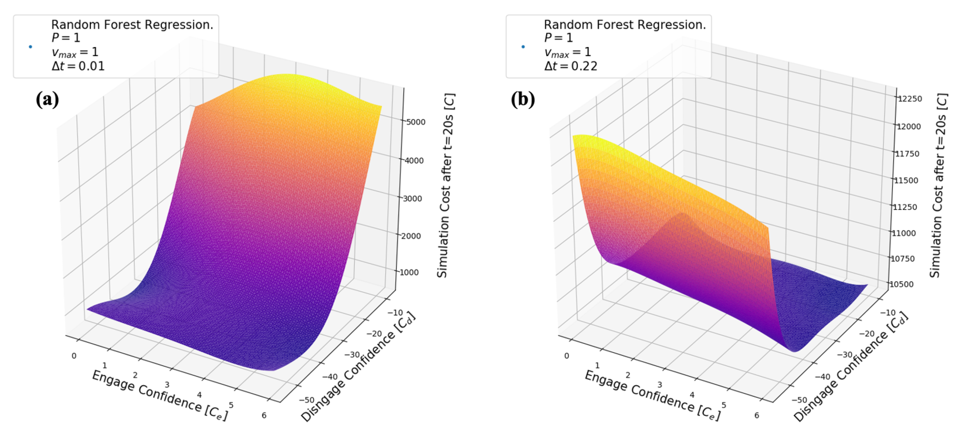
6.2. Random Forest Results

The Random Forest Regression (RFR) algorithm run with 1000 estimators, minimum number of samples required at leaf 40, and minimum number of samples to split 20. The fit was obtained for the same area. Figure 8 shows two cross sections in R 3 for different values in the RFR best-fit hypercurve space ( R 5 ). In both cases Figure 8a,b, 3 variables are kept constant indicated at the legend, so that the effect of the engage and disengage confidence threshold can be seen in the final simulation cost. Compared to Figure 6 it seems as if there is a fundamental agreement on the shape of the two functions where at low Δ t cost seems to decrease with disengagement confidence, whereas at higher Δ t cost is remaining at the order of 10,000.
The minimum vector θ R F R m i n for the Random Forest Regression fit was determined in (25) using the previously described method. Its final cost function is C ( θ R F R m i n ) = 554.89 . A randomly generated simulation procession with that value is shown in Figure 9. Figure 9 serves as an illustrative confirmation of the increase in the aggregation efficiency by minimizing the cost function. The final cost of this simulation was 792 whereas the predicted cost was 555.
θ R F R m i n = 1.000 1.000 0.002 5.269 38.52

7. Discussion

7.1. Model Novelty

The strength of the proposed model lies in the provision of an alternate pathway to aggregation than spatial algorithms, while maintaining a certain level of agent intelligence. Specifically, allowing for nodes to have a kind of operational intelligence with single celled memory allows for a simplification of the information provided by the field itself. In other words, if nodes were reduced to the level of zero “intelligence” (e.g., iron fillings), even though miniaturization would be enabled, very sophisticated equipment would be needed for the environment to provide the aggregation information, limiting the scalability and independence of the swarm. Attempting to attain these qualities by increasing nodal “intelligence” through semiconductor devices imposes a challenge in miniaturization. Therefore, achieving the appropriate balance between agent information processing capacity and environment mediated ques allows for a greater expansion of the application space of swarm robotics.

7.2. Limitations and Future Research

The model proposed has a primitive character compared to other discrete models for swarm aggregation. Some practical limitations include the handling of obstacles by the nodes. In the case where are linear obstacle is placed perpendicular to a straight line connecting the centers of mass of two tasks, aggregation will be hindered or entirely prevented as nodes do not have the appropriate sensors to check for the obstacle. This issue could be resolved by introducing a randomly dynamically alternating velocity component added to each nodes velocity such that the node can escape from situations where its direction is blocked by an obstacle while still converging in the general direction towards the task. We were hesitant to implement such solution, as introducing controlled randomness conflicts with the aim of providing an aggregation model where nodes do not perform any discrete operations. This approach, however, could have solved a different issue evident in the procession figures of depicting the simulation runs. Specifically, the tasks located at the vertexes of the smallest enclosing polygon lack even agent distribution, with the plethora of nodes located at the inner side of the task. Introducing randomness in the velocity would result in nodes traveling further inside the task allowing for complete coverage.

8. Conclusions

In this paper an attempt on the relaxation of the traditionally spatially discrete algorithms for solving the aggregation problem in swarm robotics was presented. It is believed that by providing a model that does not rely on discrete states for its operation, agent miniaturization can be achieved. That is due to the fact that dependence on certain components with a limit in their minimum size (i.e., transistors, memories) was eliminated. Specifically, by designing swarm agents with physical properties that follow the previously described mathematical model, we showed the emergence of a stigmergic aggregation behavior at discrete sites with unequal number of nodes. A quantitative method for aggregation evaluation in robotic swarms is also proposed that allows for optimization using curve fitting and minimization techniques.
It was observed that optimization using Linear Multivariable Polynomial Regression and Random Forest Regression to obtain the best fit of the generated data set, provided similar results (average percentage difference of 6.22%). This outcome serves as a validation both the optimized result in the examined space as well as the methodology used to arrive to that. The optimized swarm illustrated a significant improvement in the aggregation cost as illustrated by the simulation procession captures.

Author Contributions

Conceptualization, P.O.; Data curation, P.O.; Formal analysis, P.O.; Investigation, P.O.; Methodology, P.O.; Project administration, P.O. and S.P.; Resources, P.O.; Software, P.O.; Supervision, S.P.; Validation, P.O. and S.P.; Visualization, P.O.; Writing—original draft, P.O.; Writing—review & editing, S.P. All authors have read and agreed to the published version of the manuscript.

Funding

Article Processing Fees were covered by New York University Abu Dhabi, PO Box 129188, UAE.

Acknowledgments

We would like to thank New York University Abu Dhabi Department of Natural Sciences and especially professor Lotfi Benabderrahmane for providing helpful insights as well as NYUAD’s High Performance Computing team for proving access to their computational resources. Furthermore, we would like to sincerely thank professor Matthew Karau, Chenhe Gu, professor Dave Russel, and Daniel Chirita for insightful discussions.

Conflicts of Interest

The authors declare no conflict of interest.

References

  1. Tan, Y.; Zheng, Z.Y. Research Advance in Swarm Robotics. Def. Technol. 2013, 9, 18–39. [Google Scholar] [CrossRef] [Green Version]
  2. Mohan, Y.; Ponnambalam, S.G. An extensive review of research in swarm robotics. In Proceedings of the World Congress on Nature and Biologically Inspired Computing, NABIC 2009, Coimbatore, India, 9–11 December 2009; pp. 140–145. [Google Scholar] [CrossRef]
  3. Sharkey, A.J.C.; Sharkey, N. The application of swarm intelligence to collective robots. In Advances in Applied Artificial Intelligence; IGI Global: Hershey, PA, USA, 2006; pp. 157–185. [Google Scholar] [CrossRef]
  4. Nedjah, N.; Junior, L.S. Review of methodologies and tasks in swarm robotics towards standardization. Swarm Evol. Comput. 2019, 50, 100565. [Google Scholar] [CrossRef]
  5. Barca, J.C.; Sekercioglu, Y.A. Swarm robotics reviewed. Robotica 2013, 31, 345–359. [Google Scholar] [CrossRef] [Green Version]
  6. Elston, J.; Frew, E.W. Hierarchical distributed control for search and tracking by heterogeneous aerial robot networks. In Proceedings of the IEEE International Conference on Robotics and Automation, ICRA, Pasadena, CA, USA, 19–23 May 2008; pp. 170–175. [Google Scholar] [CrossRef]
  7. Yu, J.; Wang, B.; Du, X.; Wang, Q.; Zhang, L. Ultra-extensible ribbon-like magnetic microswarm. Nat. Commun. 2018, 9, 3260. [Google Scholar] [CrossRef] [PubMed] [Green Version]
  8. Bayindir, L. A review of swarm robotics tasks. Neurocomputing 2016, 172, 292–321. [Google Scholar] [CrossRef]
  9. Rambabu, B.; Venugopal Reddy, A.; Janakiraman, S. Hybrid Artificial Bee Colony and Monarchy Butterfly Optimization Algorithm (HABC-MBOA)-based cluster head selection for WSNs. J. King Saud Univ. Comput. Inf. Sci. 2019. [Google Scholar] [CrossRef]
  10. Varughese, J.C.; Thenius, R.; Leitgeb, P.; Wotawa, F.; Schmickl, T. A Model for Bio-Inspired Underwater Swarm Robotic Exploration. IFAC-PapersOnLine 2018, 51, 385–390. [Google Scholar] [CrossRef]
  11. Zhao, H.; Zhang, C. A decomposition-based many-objective artificial bee colony algorithm with reinforcement learning. Appl. Soft Comput. 2020, 86, 105879. [Google Scholar] [CrossRef]
  12. Correll, N.; Martinoli, A. Modeling and designing self-organized aggregation in a swarm of miniature robots. Int. J. Robot. Res. 2011, 30, 615–626. [Google Scholar] [CrossRef]
  13. Garnier, S.; Gautrais, J.; Asadpour, M.; Jost, C.; Theraulaz, G. Self-Organized Aggregation Triggers Collective Decision Making in a Group of Cockroach-Like Robots. Adapt. Behav. 2009, 17, 109–133. [Google Scholar] [CrossRef]
  14. Garnier, S.; Jost, C.; Jeanson, R.; Gautrais, J.; Asadpour, M.; Caprari, G.; Theraulaz, G. Aggregation Behaviour as a Source of Collective Decision in a Group of Cockroach-Like-Robots. In Advances in Artificial Life; Capcarrère, M.S., Freitas, A.A., Bentley, P.J., Johnson, C.G., Timmis, J., Eds.; Springer: Berlin/Heidelberg, Germany, 2005; pp. 169–178. [Google Scholar]
  15. Hamilton, W. Geometry for the selfish herd. J. Theor. Biol. 1971, 31, 295–311. [Google Scholar] [CrossRef]
  16. Hoare, D.; Couzin, I.; Godin, J.G.; Krause, J. Context-dependent group size choice in fish. Anim. Behav. 2004, 67, 155–164. [Google Scholar] [CrossRef]
  17. Romano, D.; Elayan, H.; Benelli, G.; Stefanini, C. Together We Stand–Analyzing Schooling Behavior in Naive Newborn Guppies through Biorobotic Predators. J. Bionic Eng. 2020, 17, 174–184. [Google Scholar] [CrossRef]
  18. Valentini, G.; Brambilla, D.; Hamann, H.; Dorigo, M. Collective Perception of Environmental Features in a Robot Swarm. In Swarm Intelligence; Dorigo, M., Birattari, M., Li, X., López-Ibáñez, M., Ohkura, K., Pinciroli, C., Stützle, T., Eds.; Springer International Publishing: Berlin, Germany, 2016; pp. 65–76. [Google Scholar]
  19. Arvin, F.; Turgut, A.E.; Krajník, T.; Yue, S. Investigation of cue-based aggregation in static and dynamic environments with a mobile robot swarm. Adapt. Behav. 2016, 24, 102–118. [Google Scholar] [CrossRef] [Green Version]
  20. Brambilla, M.; Ferrante, E.; Birattari, M.; Dorigo, M. Swarm robotics: A review from the swarm engineering perspective. Swarm Intell. 2013, 7, 1–41. [Google Scholar] [CrossRef] [Green Version]
  21. Dorigo, M.; Bonabeau, E.; Theraulaz, G. Ant algorithms and stigmergy. Future Gener. Comput. Syst. 2000, 16, 851–871. [Google Scholar] [CrossRef]
  22. Babaoglu, O.; Canright, G.; Deutsch, A.; Di Caro, G.A.; Ducatelle, F.; Gambardella, L.M.; Ganguly, N.; Jelasity, M.; Montemanni, R.; Montresor, A.; et al. Design patterns from biology for distributed computing. ACM Trans. Auton. Adapt. Syst. 2006, 1, 26–66. [Google Scholar] [CrossRef] [Green Version]
  23. Di Caro, G.; Dorigo, M. AntNet: Distributed stigmergetic control for communications networks. J. Artif. Intell. Res. 1998, 9, 317–365. [Google Scholar] [CrossRef]
  24. Gordon, D.M. Local Regulation of Trail Networks of the Arboreal Turtle Ant, Cephalotes goniodontus. Am. Nat. 2017, 190, E156–E169. [Google Scholar] [CrossRef]
  25. Gordon, D.M.; Goodwin, B.C.; Trainor, L.E.H. A parallel distributed model of the behaviour of ant colonies. J. Theor. Biol. 1992, 156, 293–307. [Google Scholar] [CrossRef] [Green Version]
  26. Gordon, D.M. From division of labor to the collective behavior of social insects. Behav. Ecol. Sociobiol. 2016, 70, 1101–1108. [Google Scholar] [CrossRef] [PubMed] [Green Version]
  27. Dorigo, M.; Blum, C. Ant colony optimization theory: A survey. Theor. Comput. Sci. 2005, 344, 243–278. [Google Scholar] [CrossRef]
  28. Dorigo, M.; Birattari, M.; Stützle, T. Ant colony optimization artificial ants as a computational intelligence technique. IEEE Comput. Intell. Mag. 2006, 1, 28–39. [Google Scholar] [CrossRef]
  29. Socha, K.; Dorigo, M. Ant colony optimization for continuous domains. Eur. J. Oper. Res. 2008, 185, 1155–1173. [Google Scholar] [CrossRef] [Green Version]
  30. Shlyakhov, N.E.; Vatamaniuk, I.V.; Ronzhin, A.L. Survey of Methods and Algorithms of Robot Swarm Aggregation. J. Physics Conf. Ser. 2017, 803, 012146. [Google Scholar] [CrossRef]
  31. Abu-Shikhah, N.; Elkarmi, F.; Aloquili, O.M. Medium-term electric load forecasting using multivariable linear and non-linear regression. Smart Grid Renew. Energy 2011, 2, 126. [Google Scholar] [CrossRef] [Green Version]
  32. Sauerbrei, W.; Meier-Hirmer, C.; Benner, A.; Royston, P. Multivariable regression model building by using fractional polynomials: Description of SAS, STATA and R programs. Comput. Stat. Data Anal. 2006, 50, 3464–3485. [Google Scholar] [CrossRef]
  33. Liaw, A.; Wiener, M. Classification and regression by randomForest. R News 2002, 2, 18–22. [Google Scholar]
  34. Segal, M.R. Machine Learning Benchmarks and Random Forest Regression; University of California: San Francisco, CA, USA, 2004. [Google Scholar]
  35. Fei, Y.; Rong, G.; Wang, B.; Wang, W. Parallel L-BFGS-B algorithm on GPU. Comput. Graph. 2014, 40, 1–9. [Google Scholar] [CrossRef]
  36. Liu, D.C.; Nocedal, J. On the limited memory BFGS method for large scale optimization. Math. Program. 1989, 45, 503–528. [Google Scholar] [CrossRef] [Green Version]
  37. Iwamatsu, M.; Okabe, Y. Basin hopping with occasional jumping. Chem. Phys. Lett. 2004, 399, 396–400. [Google Scholar] [CrossRef] [Green Version]
  38. Verma, A.; Schug, A.; Lee, K.H.; Wenzel, W. Basin hopping simulations for all-atom protein folding. J. Chem. Phys. 2006, 124, 044515. [Google Scholar] [CrossRef] [PubMed]
  39. Wales, D.J.; Doye, J.P.K. Global Optimization by Basin-Hopping and the Lowest Energy Structures of Lennard-Jones Clusters Containing up to 110 Atoms. J. Phys. Chem. A 1997, 101, 5111–5116. [Google Scholar] [CrossRef] [Green Version]
Figure 1. Example of a task Indicator distribution. The task is centered at the origin with an arbitrary radius. The intensity profile (z-axis) is represented in arbitrary units. It is evident that the intensity is non-zero everywhere in the field, with a radical increase near the edge of the circular task.
Applsci 10 01067 g001
Figure 2. 3D visualization of a randomly generated intensity space with two tasks on a 2D field (blue and red) with different radii and different number of nodes.
Applsci 10 01067 g002
Figure 3. (a) Simulation of node moving radially through the center of a task where randomly assigned nodes are performing the task close to its radius. (b) The equivalent Confidence Function for the simulated scenario is shown.
Applsci 10 01067 g003
Figure 4. Illustration of a procession in time (ad) of a simulation with 8 randomly placed tasks, with random radii, in a 5 × 5 unit field, where 100 nodes are placed at time 0 at random locations. In the legend “Task 0: nodes: 9” represents a task with ID 0 and expected 9 nodes to aggregate.
Applsci 10 01067 g004
Figure 5. Illustration of a procession in time (ad) of a simulation with 4 randomly placed tasks, with random radii, in a 5 × 5 unit field, where 150 nodes are placed at time 0 at random locations. In the legend “Task 0: nodes: 27” represents a task with ID 0 and expected 27 nodes to aggregate.
Applsci 10 01067 g005
Figure 6. Illustration of 3D cross sections of the 6D best-fit hypercurve for the cost of a simulation obtained using Linear Multivariable Polynomial Regression. The colormap indicates higher confidence values with warmer (yellower) colors. 3 of the simulation variables (P, v m a x , and Δ t ) were kept constant at the values shown in the legend, while the two others C e and C d were graphed with the equivalent cost in the z-axis. (a) Cross section of arbitrarily chosen lower Δ t value, where cost appears to be at a low value. (b) Cross section of arbitrarily chosen higher Δ t value, where cost appears to be higher on average than (a).
Applsci 10 01067 g006
Figure 7. Illustration of a procession in time (ad) of a simulation with 5 randomly placed tasks, with random radii, in a 5 × 5 unit field, where 250 nodes are placed at time 0 at random locations. Each task is associated with a random color seen in the legend. The color of each node represents its target task. The small black arrow of each node indicates the direction and magnitude of the velocity of said node. In the legend “Task 0: nodes: 9” represents a task with ID 0 and expected 9 nodes to aggregate. The parameters used to run the simulation were θ L R m i n seen in (24) and obtained by minimizing the hypercurve obtained by Linear Multivariable Polynomial Regression.
Applsci 10 01067 g007
Figure 8. Illustration of 3D cross sections of the 6D best-fit hypercurve for the cost of a simulation obtained using Random Forest Regression. The colormap indicates higher confidence values with warmer (yellower) colors. 3 of the simulation variables (P, v m a x , and Δ t ) were kept constant at the values shown in the legend, while the two others C e and C d were graphed with the equivalent cost in the z-axis. (a) Cross section of arbitrarily chosen lower Δ t value, where cost appears to be at a low value. (b) Cross section of arbitrarily chosen higher Δ t value, where cost appears to be higher on average than (a).
Applsci 10 01067 g008
Figure 9. Illustration of a procession in time (ad) of a simulation with 5 randomly placed tasks, with random radii, in a 5 × 5 unit field, where 250 nodes are placed at time 0 at random locations. Each task is associated with a random color seen in the legend. The color of each node represents its target task. The small black arrow of each node indicates the direction and magnitude of the velocity of said node. In the legend “Task 0: nodes: 9” represents a task with ID 0 and expected 9 nodes to aggregate. The parameters used to run the simulation were θ R F R m i n seen in (25) and obtained by minimizing the hypercurve obtained by Random Forest Regression.
Applsci 10 01067 g009
Table 1. Simulation Variable Bounds for Data Set Generation.
VariableInclusive Bounds
From Value [au] a To Value [au] a
P1.001.00
v m a x 1.001.00
Δ t 0.023.00
C e 0.0010.00
C d −540.00
a Relevant abstract unit.

