Article

Enhancement of Power System Transient Stability by the Coordinated Control between an Adjustable Speed Pumping Generator and Battery

1
Department of Electrical and Electronic Engineering, Kitami Institute of Technology (KIT), Kitami 090-8507, Hokkaido, Japan
2
Hokkaido Electric Power Network Inc., Sapporo 060-0041, Hokkaido, Japan
*
Author to whom correspondence should be addressed.
Appl. Sci. 2020, 10(24), 9034; https://doi.org/10.3390/app10249034
Submission received: 18 November 2020 / Revised: 10 December 2020 / Accepted: 14 December 2020 / Published: 17 December 2020
(This article belongs to the Special Issue Wind Generators: Technology and Trends)

Abstract

:
The penetration level of large-scale wind farms into power systems has been increasing significantly, and the frequency stability and transient stability of the power systems during and after a network fault can be negatively affected. This paper proposes a new control method to improve the stability of power systems that are composed of large wind farms, as well as usual synchronous generators. The new method is a coordinated controlling method between an adjustable-speed pumping generator (ASG) and a battery. The coordinated system is designed to improve power system stability during a disconnection in a fixed-rotor-speed wind turbine with a squirrel cage-type induction generator (FSWT-SCIG)-based wind farm due to a network fault, in which a battery first responds quickly to the system frequency deviation due to a grid fault and improves the frequency nadir, and then the ASG starts to supply compensatory power to recover the grid frequency to the rated frequency. The performance of the proposed system was confirmed through simulation studies on a power system model consisting of usual synchronous generators (SGs), an ASG, a battery, and an SCIG-based wind farm. Simulation results demonstrated that the proposed control system can enhance the stability of the power system effectively.

1. Introduction

Over the last several decades, environmental problems such as global warming have been becoming serious, and renewable energies such as solar and wind energies have attracted much attention as a countermeasure against the issues. Among renewable energy sources, wind power generation has been installed throughout the world because of its low environmental influence. Wind power generation has various strong points, including that the cost is relatively less, and the efficiency of the energy conversion is higher, in general, than other electricity generation systems that are based on renewable energy. However, when a network fault such as a grounding fault occurs in the vicinity of a wind farm (WF) in a power system with a large-scale WF, the WF can become unstable and then trip from the grid according to the fault ride-through (FRT) grid code [1,2] after the fault. As a result, grid frequency decreases significantly, and the power system can be unstable because the generated power from the WF is lost.
To solve such problems, stabilizing control by using a storage battery has been proposed [3,4,5,6,7]. Since storage batteries have a fast response speed and high controllability, they can be used effectively for enhancing power system frequency stability, as well as power system transient stability. However, the cost of storage batteries is, in general, very expensive. Therefore, it is often difficult to solve problems of system frequency stability and transient stability by using only a large-scale storage battery in the power system. On the other hand, adjustable-speed pumping generators (ASGs) [8,9,10,11,12,13,14,15], which are used as pumping generators in pumping hydropower plants, can be a powerful countermeasure against power system instability. ASGs were first put into practical use in Japan [8], and several ASGs are presently in operation in Japan. Additionally, ASGs have been widely adopted in pumping hydropower plants around the world [14]. Therefore, if there is an ASG in a power system, it should be utilized effectively for enhancing the power system stabilities cooperatively with batteries, and as a result the number of batteries can be reduced. Although an ASG has a large stored energy capacity, its response speed is not as fast when compared with a storage battery, and it is not so easy for it to respond quickly to an event, such as a trip accident of the WF. In contrast, although storage batteries have a high response speed, their rated power and energy storage capacity are, in general, not as large, and they cannot supply sufficient power to the grid, such as in the case of an accident with large generation power loss due to a network fault.
Considering this background, this paper presents a new control system in which an ASG and battery supply and compensate power coordinately to a power system to enhance the frequency stability and the transient stability of the system during disconnection from a large WF. In the proposed control strategy, the ASG ensures the amount of compensatory power, and the battery ensures the control speed of the compensatory power. Therefore, the battery first responds quickly to the system frequency deviation due to a grid fault and improves the frequency nadir, and then the ASG starts to supply the compensatory power to recover the system frequency to the rated frequency. Although it is almost impossible for a usual fixed-rotor-speed pumping generator (FSG) to achieve such control for grid system stabilization, the proposed coordinated control between an ASG and storage battery can enhance grid system stability. Although there have been many reports so far discussing several characteristics of ASGs [8,9,10,11,12,13,14,15], few have proposed a coordinated and effective control system between an ASG and battery for enhancing power system frequency stability, as well as transient stability. Both the ASG and the battery have an ability to enhance power system stability; however, each of them has weak points, respectively, as stated above. The new control system proposed in this paper is a coordinated system between an ASG and battery that is designed to make up for each weak point. Therefore, the proposed system is significantly novel.
Simulation analyses by using a PSCAD/EMTDC simulator were performed on a model system consisting of usual synchronous generators, a squirrel cage induction generator (SCIG)-based WF, and a battery. The simulation results are presented in the paper to show the validity of the proposed method.
The remainder of the present paper is organized as follows: Section 2 presents the models used in the simulation analyses, that is, the model system, governor models, ASG, and battery; Section 3 explains the proposed coordinated control method between the ASG and the battery; Section 4 presents the conditions and results of the simulation analyses regarding the coordinated stabilizing control and the minimum necessary power rating of the battery; and Section 5 concludes the paper.

2. Power System Model

2.1. Model System

The power system model used in the simulation studies in this paper is depicted in Figure 1, where circuit parameters and power flow conditions are presented in the figure. It was constructed based on the Institute of Electrical and Electronics Engineers (IEEE) 9-bus standard model [16]. The system consisted of a 100 MVA ASG and two synchronous generators (SG1 and SG2). SG1 was a 200 MVA load frequency control (LFC) hydropower generator, and SG2 was a 300 MVA governor-free (GF) thermal power generator. In addition, an SCIG-based WF (60 MVA), a storage battery (15 MVA), and three loads (Loads A, B, and C) were connected to the system [17]. The ASG was operating in generating mode or pumping mode in the analysis. In addition, a simulation analysis in which the ASG was replaced with a usual fixed-rotor-speed pumping generator (FSG) of the same power rating as that of the ASG was also performed for comparing the performance between the ASG and FSG. Two power flow conditions are shown in the figure in blue and red colors, which correspond to the generating operation mode and the pumping operation mode of the ASG, respectively. Various conditions of the system and each generator, except the circuit parameters and power flow conditions, are summarized in Table 1. The total load in the generating mode of ASG was set at 480 MW, 80% of the total generating capacity of the synchronous generators and ASG, i.e., 600 MVA. The total load in the pumping mode was set at 335 MW because the ASG (or FSG) operated in pumping mode as a load and the output of SG1 and SG2 were set to values less than those in the generating mode.

2.2. Governor Model

The governor model of the hydroelectric generator, SG1, adopted in this paper is depicted in Figure 2, and the governor model of the thermal generator, SG2, is depicted in Figure 3 [18,19], where:
  • Sg: Deviation of rotor speed
  • 65M: Load setting (output reference value)
  • 77M: Load limit (65M + rated output × governor operating margin (PLM) (%))
  • PLM: Governor operating margin (%) (a percentage of the rated output)
  • Pm: Turbine output
The LFC system model used for SG1 is shown in Figure 4. The load setting (65M) and load limit (77M) are shown in Table 1. The LFC system provided an output signal to the LFC generator (SG1) according to the frequency deviation. The LFC signal was received as 65M, and then the plant output was changed. A rate limiter of 100% MW/min for the LFC signal was installed at the entrance of the 65M signal. The governor models used in this paper are Institute of Electrical Engineers of Japan (IEEJ) standard models.

2.3. Wind Turbine Model

A simplified method for modeling the wind turbine was adopted in this paper, i.e., the MOD-2 model [20] was used for the SCIG-based fixed-rotor speed wind turbine generator and its characteristics are expressed by the following equations:
Pωtb = (1/2) ρCp (λ,β) πR2Vw3
Cp (λ, β) = (1/2) (Г − 0.022β2 − 5.6) e−0.17Г
Λ = (ωWtbR)/Vw
Г = (R/λ) (3600/1609)
Ct(λ) = Cp(λ)/λ
τM = (1/2) ρCt (λ) πR3Vw2
where Pwtb: wind turbine power (W); λ: tip speed ratio; R: radius of wind turbine (m); ωWtb: wind turbine rotation speed (rad/s); β: pitch angle (deg); Vw: wind speed (m/s); ρ: air density (kg/m3); Cp: power coefficient; Ct: torque coefficient; and τM: wind turbine torque (Nm). The Cp–λ curves are shown in Figure 5 for several values of β.

2.4. Adjustable-Speed Pumping Generator (ASG)

In the following, the model of the ASG, its rotor excitation system, and its water wheel model are explained [21,22].

2.4.1. ASG Model

ASGs have a similar structure to those of wound-rotor induction generators, and their stators and rotors are both equipped with three phase windings. To enable adjustable speed operation in a pumping generator, variable frequency (slip frequency) three-phase AC currents are supplied to the rotor windings to generate a magnetic field rotating on the rotor. Since the summation of the rotating speed of the magnetic field and the generator rotor speed is equal to the speed corresponding to the system frequency, it becomes possible for a generator to operate in synchronization with the grid frequency. Consequently, adjustable-speed operation becomes possible by controlling the velocity of a rotating magnetic field, i.e., the frequency of the excitation current supplied to the three-phase rotor windings. Though a cycloconverter was adopted as an excitation current source, a self-commutated inverter such as an IGBT PWM inverter is currently often used. In this study, a self-commutated inverter was considered as an excitation current source.

2.4.2. Rotor Excitation System of the ASG

Figure 6 depicts the basic structure of the rotor excitation system of the ASG. Excitation power was supplied from the stator circuit, then converted to DC power by the stator side converter, and, finally, three-phase excitation current of slip frequency was provided to the rotor windings through the inverter. As a result, the rotor speed of the ASG could deviate from the synchronous speed by the slip frequency. When the ASG was operating in generating mode, the rotor speed was, in general, controlled by the hydro turbine efficiency to be maximum speed. The d-axis component of the stator current on the d–q axis frame defined on the stator voltage reference was proportional to the generator’s active output power, and the q-axis component was proportional to the reactive output power. Consequently, by controlling the magnitude and phase angle of the excitation current supplied to the rotor windings, the stator-side active power and reactive power of the generator could be controlled independently. In addition, the power factor of the converter input and the DC-link voltage could be controlled by changing the magnitude and phase angle of the converter AC-side voltage.
Figure 7 shows a more detailed structure of the ASG secondary excitation circuit, which is based on Proportional and Integral (PI) controllers. The control system of the inverter is expressed on the d–q axis frame on the stator voltage reference, while the control system of the converter is expressed on the d’–q’ axis frame on the voltage reference at the high-voltage side of the converter transformer. Voltage references of the reference frames were obtained through the Phase Lock Loop (PLLs).

2.4.3. Water Wheel Model of the ASG

The ASG pumping load is, in general, proportional to the cube of the rotor speed under the pumping operation, and thus the following equation holds:
(PL/PL0) = (ηL/ηL0)(ωm/ωm0)3
where ωm is the rotation speed of the ASG, PL denotes the pumping load at rotor speed ωm, and ηL denotes pump efficiency. The subscript “0” refers to values at the rated (synchronous) speed. In addition, it holds approximately ηLηL0. Consequently, the pumping load torque can be approximately expressed by the following equation:
τL τL0(ωm/ωm0)2
Figure 8 shows the pumping load model in the pumping operation derived from Equations (7) and (8). In addition, Figure 9 shows the ASG governor model under the generating operation [23] used in this paper, which is one of the standard IEEE water wheel models.

2.5. Battery System Model

The battery system depicted in Figure 10 [24] was adopted in this paper. In this paper, the simple battery model that was adopted is represented by ideal voltage sources in place of an IGBT inverter.

3. Proposed Control Method

A new control system was designed in which the ASG and battery supply compensatory power in coordination with the power system to enhance the stability of the power system. In the control system, the battery first responds quickly to the system frequency deviation due to a grid fault and improves the frequency nadir, and then the ASG starts to supply the compensatory power to recover the system frequency to the rated frequency.
Figure 11 shows diagrams of the proposed ASG control systems for the generating operation mode and the pumping operation mode, respectively. In the control systems, the frequency deviation of the system was passed through the PGain, divided by PASG, and then input to the rate limiter of 100 (%MW/min). The output from the rate limiter was added by PASG0 (the steady-state reference output), then passed through the upper/lower limiter, and finally the reference signal, ASG_Pref, was obtained. It was clear that the ASG had a weak point and that its output could not be increased/decreased rapidly due to the 100 (%MW/min) rate limiter (this value is a standard value for pumping generators in Japan). This weak point was compensated for by the battery as follows.
Figure 12 depicts a diagram of the battery controller. In the battery controller, PIdeal is the ASG signal without the rate limiter, and the difference between PIdeal and PASG Signal was utilized to determine the battery output reference signal. Consequently, the fast component in the deviation of the grid frequency that the ASG could not compensate for was supplied by the battery. As a result, if the speed of the grid frequency deviation was slow, the battery supplied no power.

4. Simulation Analysis

4.1. Conditions of the Simulation Analysis

In order to demonstrate the performance of the new control system, simulation studies were done on the simulator PSCAD/EMTDC for the two operating modes of the ASG, i.e., the generating mode and the pumping mode. In addition, two cases were analyzed in each ASG mode. Table 2 describes the conditions of the two cases. An FSG was operating in place of the ASG and no frequency control was activated in Case 1, and the ASG and the battery were operating and the proposed control was activated in Case 2. Table 3 shows the rotor speed references for the FSG and ASG. The wind speed of the wind generator was fixed at 11 m/s according to the assumption that wind speed does not change considerably within the brief period of the transient stability simulation analysis.

4.2. Fault Condition

A three-phase grounding fault was considered in this study. The fault occurred at 0.1 s in a circuit of the double-circuit transmission line nearby Load C, as depicted in Figure 1, then the faulty line was opened at 0.2 s, and it was reclosed at 1.0 s. Figure 13 demonstrates the voltage responses of the wind farm for the two operating modes of the ASG (FSG), in which the black line represents the FRT characteristic adopted in this paper [1]. Consequently, the wind farm was decoupled from the system at 1.6 s in the following analysis because its voltage did not satisfy the FRT code.

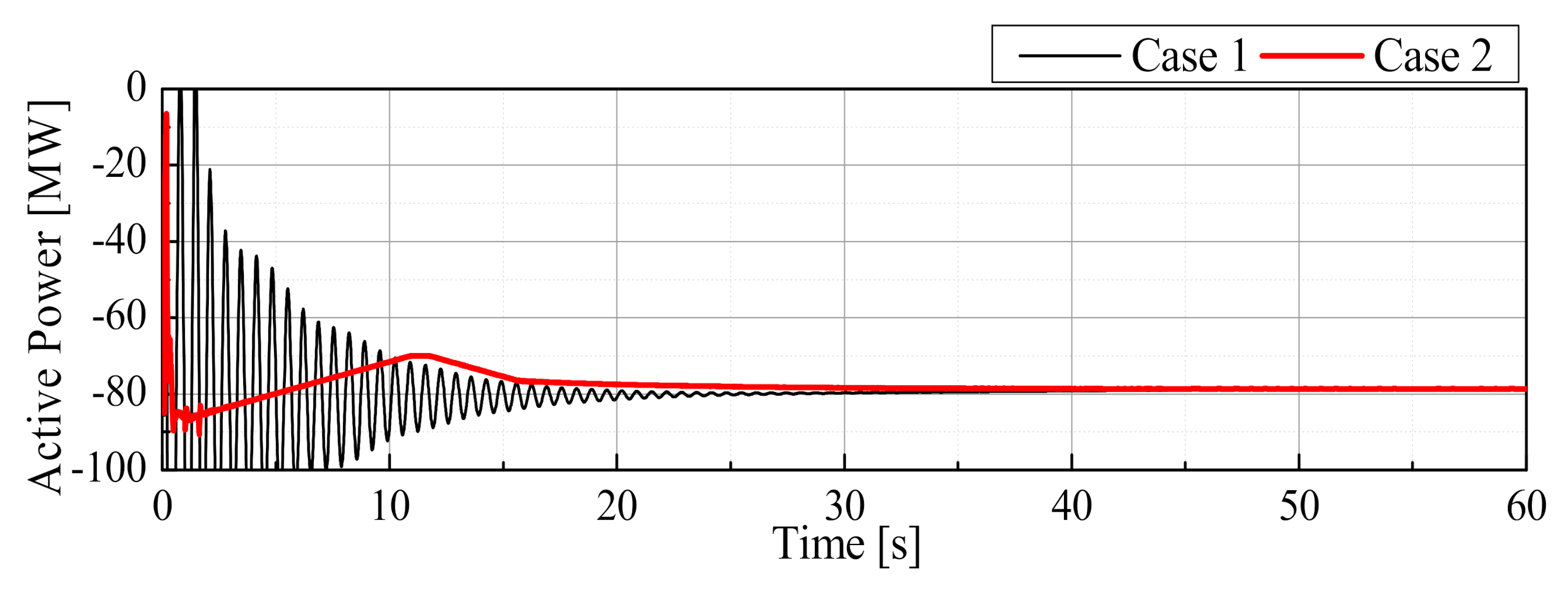
4.3. Simulation Results

The simulation results are presented in Figure 14, Figure 15, Figure 16, Figure 17, Figure 18, Figure 19, Figure 20 and Figure 21, in which Figure 14, Figure 15, Figure 16 and Figure 17 show the responses in the generating operation mode, and Figure 18, Figure 19, Figure 20 and Figure 21 show the responses in the pumping operation mode. It is seen in Figure 14 and Figure 18 that, in the case of the FSG in Case 1, the grid frequency decreased greatly, and the power system became unstable. This was because the wind farm was decoupled from the grid according to the FRT grid code, as shown in Figure 13, and then the output from the wind farm was lost. In contrast to Case 1, in the case of the ASG in Case 2, it is observed in Figure 14 and Figure 18 that the proposed control of the battery and ASG was successfully performed, and the grid frequency could be returned to the rated frequency in spite of the disconnection of the wind farm. Figure 15 and Figure 19 show the output powers of the FSG (Case 1) and ASG (Case 2), and Figure 16 and Figure 20 show the responses of the rotor speed of each generator, in which it is seen that the ASG, which was controlled based on the proposed method, controlled its output effectively by adjusting its rotor speed to maintain the stability of the system, and as a result the system could be stabilized, as can be seen in Figure 14 and Figure 18. Figure 17 and Figure 21 show responses of the battery output in Case 2 (positive value corresponds to discharge), in which it is seen that the battery also controlled its output based on the proposed method and contributed effectively to the stabilization of the system. It is seen in Figure 15, Figure 17, Figure 19, and Figure 21 that the battery increased its output to the maximum level (rated power) rapidly after the disconnection of the wind farm in Case 2 (Figure 17 and Figure 21), and then the ASG increased its output in the generating operation mode (Figure 15) and decreased its pump load in the pumping operation mode (Figure 19) to bring back the system frequency to the rated frequency. The operation of the ASG followed the control action of the battery because the output of the ASG was limited by the rate limiter, as explained before. In this way, the ASG and the battery controlled each output cooperatively to stabilize the power system.
As a result, it was concluded that the proposed coordinated control of the battery and the ASG could maintain the stability of the grid system effectively during a disconnection of the WF due to a network fault.

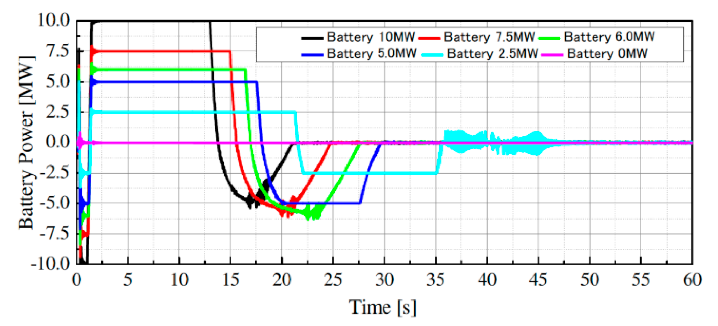
4.4. Consideration of the Minimum Battery Capacity for the Stabilizing Control

In this section, the minimum necessary power rating of the battery in the proposed coordinated control system is evaluated since the power rating of the battery should be reduced to as small as possible because of its very expensive cost. Simulation analyses of Case 1 and Case 2 shown in Table 2 for the same network fault condition explained in the previous section were performed, in which the ASG or FSG was in the pumping operation and the power rating of the battery was changed from 0 MW (no battery) to 10 MW.
Figure 22 shows the system frequency responses, in which “No Control” means Case 1 (the FSG was in operation), and its response was the same as that in Figure 18; and the six cases of “Battery 0 MW” to “Battery 10 MW” mean Case 2, in which the ASG and the battery were in operation (in the case of “Battery 0 MW”, the battery was not connected to the grid). It is observed in Figure 22 that the grid frequency could return to the rated frequency in Case 2 even if there was no battery (0 MW). However, the system frequency reached 48.5 Hz or below when the battery rating was 2.5 MW and 0 MW. In Japan, 48.5 Hz is usually the minimum (lowest) frequency at which usual synchronous generators can be connected to the grid system. Therefore, it is seen in the figure that a 5 MW battery was necessary for stabilizing the power system without a trip of the usual synchronous generators. Figure 23 and Figure 24 show responses of the output power (pumping load) and rotor speed of the FSG and ASG, from which it was observed that the ASG controlled its output effectively by adjusting its rotor speed to maintain the stability of the system, but the duration of the variable speed operation became longer as the power rating of the battery became small. Finally, Figure 25 shows responses of the battery output power (positive value corresponds to discharge). It is seen in the figure that the battery controlled its output effectively to maintain the power system stably, and the duration of the maximum (rated) output became longer as the battery rating became small.
As a result, it was concluded that the battery was indispensable to the proposed coordinated control between the ASG and battery to keep the stability of the power system operating effectively during a disconnection of the WF due to a network fault.

5. Conclusions

To improve the stability of a power system with a large WF, a new control strategy was presented in this paper, in which an ASG and battery supply compensated power coordinately to a power system to improve its frequency stability and transient stability during the disconnection of a WF. In the control strategy, the ASG ensured the amount of compensatory power and the battery ensured the control speed of the compensatory power. The validity of the new control system was analyzed through simulation studies, and it was demonstrated that the battery first responded quickly to the system frequency deviation due to a grid fault followed by the disconnection of the WF and improved the frequency nadir, and then the ASG started to supply the compensatory power to recover the grid frequency to the rated frequency. As a result, it was confirmed that ASG and battery control based on the proposed new method could stabilize a power system effectively during the disconnection of a WF due to a grid fault. Consequently, it was concluded that the proposed new control system utilizing an ASG and battery has a significant value in improving the stability of power systems with a large WF.
As a future study, the authors are planning to incorporate reactive power control into the cooperative control system in order to stabilize a WF after a grid fault. Because reactive power control can contribute to maintaining system voltage, the condition of the FRT capability of a WF can be improved, and thus it can be expected that the reactive power control can stabilize the WF and then can prevent the WF from being disconnected from the grid. On the other hand, control during the operation mode change between the pumping and generating of an ASG is a serious problem that should be solved because an ASG cannot output any power during the operation mode change. The authors are going to solve the problem by utilizing an LFC hydropower plant in the cooperative control system because the response speed of LFC hydro generators is relatively fast.

Author Contributions

J.T. prepared the theoretical concept and designed the proposed control system. A.U. and R.T. designed the power system model and executed the simulation studies. J.T. wrote the manuscript. A.S., F.T., and R.N. made considerations on the simulation results. All authors have read and agreed to the published version of the manuscript.

Funding

This research has not received any external funding.

Acknowledgments

The authors wish to acknowledge Seiya Goto of Meidensha Corporation for his valuable contributions to modeling of the control systems and simulation analyses.

Conflicts of Interest

All authors declare there are no conflicts of interest. The Japan Electric Association.

References

  1. Japan Electric Association. Grid Interconnection Code (JEAC 9701-2012); Japan Electric Association: Chiyoda, Japan, 2012. [Google Scholar]
  2. Gashi, A.; Kabashi, G.; Kabashi, S.; Ahmetaj, S.; Veliu, V. Simulation the Wind Grid Code Requirements for Wind Farms Connection in Kosovo Transmission Grid. Sci. Res. Energy Power Eng. 2012, 4, 482–495. [Google Scholar] [CrossRef] [Green Version]
  3. Ono, T.; Arai, J. Frequency Control with Dead Band Characteristic of Battery Energy Storage System for Power System Including Large Amount of Wind Power Generation. IEEJ Trans. Power Energy 2012, 132, 709–717. (In Japanese) [Google Scholar] [CrossRef]
  4. Chankong, V.; Loparo, K.A. Transient Stability and Voltage Regulation in Multi-machine Power Systems Vis-à-Vis STATCOM and Battery Energy Storage. IEEE Trans. Power Syst. 2014, 30, 2404–2416. [Google Scholar]
  5. Guan, Y.; Vasquez, J.C.; Guerrero, J.M.; Wang, Y.; Feng, W. Frequency Stability of Hierarchically Controlled Hybrid Photovoltaic-Battery-Hydropower Microgrids. IEEE Trans. Ind. Appl. 2015, 51, 4729–4742. [Google Scholar] [CrossRef]
  6. Brogan, P.V.; Best, R.J.; Morrow, D.J.; McKinley, K.; Marek, L.K. Effect of BESS Response on Frequency and RoCoF During Underfrequency Transients. IEEE Trans. Power Syst. 2019, 34, 575–583. [Google Scholar] [CrossRef] [Green Version]
  7. Sato, T.; Umemura, A.; Takahashi, R.; Tamura, J. Cooperative Virtual Inertia Control of PMSG based wind generator and battery for Power System Stability Enhancement. In Proceedings of the 2nd International Conference on Smart Power & Internet Energy Systems (SPIES2020), SP0025, Bangkok, Thailand, 15–18 September 2020. [Google Scholar]
  8. Kuwabara, T.; Shibuya, A.; Furuta, H.; Kita, E.; Mitsuhashi, K. Design and dynamic response characteristics of 400 MW adjustable speed pumped storage unit for Ohkawachi Power Station. IEEE Trans. Energy Convers. 1996, 11, 376–384. [Google Scholar] [CrossRef]
  9. Schreier, J.; Bendl, M. Chomat:In Doubly Fed Asynchronous Machine with 3-Level VSI for Variable Speed Pump Storage. In Proceedings of the 14th International Conference on Man-Machine-Environment System Engineering (Lecture Notes in Electrical Engineering (318)); Springer: Berlin/Heidelberg, Germany, 2000; pp. 709–713. [Google Scholar]
  10. Chomat, M.; Schreier, L.; Bendl, J. Optimal control of power unit with doubly fed machine. In Proceedings of the IEEE International Electric Machines and Drives Conference (IEMDC 2001), Cambridge, MA, USA, 17–20 June 2001. [Google Scholar] [CrossRef]
  11. Gjengedal, T. Application of adjustable speed hydro (ASH) machines in the Norwegian power system. In Proceedings of the 2001 IEEE Porto Power Tech Proceedings, Porto, Portugal, 10–13 September 2001. [Google Scholar]
  12. Krenn, J.; Keck, H.; Sallaberger, M. Small and Mid-Size Pump-Turbines with Variable Speed. Energy Power Eng. 2013, 5, 48–54. [Google Scholar] [CrossRef] [Green Version]
  13. Muljadi, E.; Singh, M.; Gevorgian, V.; Mohanpurkar, M.; Hovsapian, R.; Koritarov, V. Dynamic modeling of adjustable-speed pumped storage hydropower plant. In Proceedings of the 2015 IEEE Power & Energy Society General Meeting, Denver, CO, USA, 26–30 July 2015. [Google Scholar] [CrossRef]
  14. Valavi, M.; Nysveen, A. Variable-Speed Operation of Hydropower Plants: A Look at the Past, Present, and Future. IEEE Ind. Appl. Mag. 2018, 24, 18–27. [Google Scholar] [CrossRef] [Green Version]
  15. Bortoni1, E.; de Souza, Z.; Viana, A.; Villa-Nova, H.; Rezek, Â.; Pinto, L.; Siniscalchi, R.; Bragança, R.; Bernardes, J., Jr. The Benefits of Variable Speed Operation in Hydropower Plants Driven by Francis Turbines. Energies 2019, 12, 3719. [Google Scholar] [CrossRef] [Green Version]
  16. Anderson, P.M.; Found, A.A. Power System Control and Stability; IEEE Press: New York, NY, USA, 1994. [Google Scholar]
  17. Rosyadi, M.; Umemura, A.; Takahashi, R.; Tamura, J.; Uchiyama, N.; Ide, K. Simplified Model of Variable Speed Wind Turbine Generator for Dynamic Simulation Analysis. IEEJ Trans. Power Energy 2015, 135, 538–549. [Google Scholar] [CrossRef]
  18. Liu, J.; Rosyadi, M.; Umemura, A.; Takahashi, R.; Tamura, J. A Control Method of Permanent Magnet Wind Generators in Grid Connected Wind Farm to Damp Load Frequency Oscillation. IEEJ Trans. Power Energy 2014, 134, 393–398. [Google Scholar] [CrossRef]
  19. Nakamura, A.; Umemura, A.; Takahashi, R.; Tamura, J.; Sakahara, A.; Tosaka, F.; Nakamoto, R. Stabilization of Power System including Wind Farm by Two-Step P and Q control of HVDC Interconnection Line. In Proceedings of the 2nd International Conference on Smart Power & Internet Energy Systems (SPIES2020), SP0014, Bangkok, Thailand, 15–18 September 2020. [Google Scholar]
  20. Wasynczuk, O.; Man, D.T.; Sullivan, J.P. Dynamic Behavior of a Class of Wind Turbine Generators During Random Wind Fluctuations. IEEE Trans. Power Appar. Syst. 1981, PAS-100, 2837–2845. [Google Scholar] [CrossRef]
  21. Tokida, A.; Tahara, S.; Yoshida, Y.; Umemura, A.; Tkahashi, R.; Tamura, J. Frequency Control of Power System with Wind Farm by Output Frequency Band Control of Adjustable-Speed Pumped-Storage Generator. In Proceedings of the 5th IET International Conference on Renewable Power Generation (RPG2016), London, UK, 21–23 September 2016. [Google Scholar]
  22. Takahashi, R.; Tamura, J.; Tada, Y.; Kurita, A. Model Derivation of Adjustable Speed Generator and its Excitation Control System. IEEJ Trans. Power Energy 2004, 124, 181–189. (In Japanese) [Google Scholar] [CrossRef] [Green Version]
  23. Working Group on Prime Mover and Energy Supply. Models for System Dynamics Performance Studies: Hydraulic turbine and turbine control models for system dynamics studies. IEEE Trans. Power Syst. 1992, 7, 167–179. [Google Scholar] [CrossRef]
  24. Onuka, S.; Umemura, A.; Takahashi, R.; Tamura, J.; Sakahara, A.; Tosaka, F.; Nakamoto, R. Frequency Control of Power System with Renewable Power Sources by HVDC Interconnection Line and Battery Considering Energy Balancing. J. Power Energy Eng. 2020, 8, 11–24. [Google Scholar] [CrossRef] [Green Version]
Figure 1. Model system.
Applsci 10 09034 g001
Figure 2. Hydro governor.
Applsci 10 09034 g002
Figure 3. Thermal governor.
Applsci 10 09034 g003
Figure 4. Load frequency control (LFC) system.
Applsci 10 09034 g004
Figure 5. Power coefficient (Cp–λ) curves for several values of pitch angle.
Applsci 10 09034 g005
Figure 6. Adjustable-speed pumping generator (ASG) configuration.
Applsci 10 09034 g006
Figure 7. Detailed structure of the ASG rotor excitation circuit.
Applsci 10 09034 g007
Figure 8. Pumping load model in pumping operation mode.
Applsci 10 09034 g008
Figure 9. ASG water wheel governor model in generating operation mode.
Applsci 10 09034 g009
Figure 10. Simple battery model.
Applsci 10 09034 g010
Figure 11. Frequency control systems of the ASG.
Applsci 10 09034 g011
Figure 12. Frequency control system of the battery.
Applsci 10 09034 g012
Figure 13. Responses of wind farm (WF) voltage and fault ride-through (FRT) grid code.
Applsci 10 09034 g013
Figure 14. System frequency (Generating Operation).
Applsci 10 09034 g014
Figure 15. ASG and fixed-rotor-speed pumping generator (FSG) output (Generating Operation).
Applsci 10 09034 g015
Figure 16. Generator rotor speed (Generating Operation).
Applsci 10 09034 g016
Figure 17. Battery output (Generating Operation).
Applsci 10 09034 g017
Figure 18. System frequency (Pumping Operation).
Applsci 10 09034 g018
Figure 19. ASG and FSG output (Pumping Operation).
Applsci 10 09034 g019
Figure 20. Generator rotor speed (Pumping Operation).
Applsci 10 09034 g020
Figure 21. Battery output (Pumping Operation).
Applsci 10 09034 g021
Figure 22. System frequency (II) (Pumping Operation).
Applsci 10 09034 g022
Figure 23. ASG and FSG output (II) (Pumping Operation).
Applsci 10 09034 g023
Figure 24. Generator rotor speed (II) (Pumping Operation).
Applsci 10 09034 g024
Figure 25. Battery output (II) (Pumping Operation).
Applsci 10 09034 g025
Table 1. Generator conditions.
-GeneratorMVAFrequency Control65M77M
ASGHydro100AFC *30.6 *11.0 *1
−0.85 *2−1.0 *2
SG1Hydro200LFC *4LFC Signal1.0
SG2Thermal300GF *50.70.735
SCIG *6Wind Farm100
Load (MW) 480 *1
335 *2
*1: Generating Operation; *2: Pumping Operation; *3: Automatic Frequency Control; *4: Load Frequency Control; *5: Governor Free; *6: Squirrel Cage Induction Generator.
Table 2. Simulation cases.
CaseExplanation
1FSG is operating and frequency control is not activated (no battery)
2Proposed control
(ASG and battery are operating based on the proposed controllers)
Table 3. Reference rotor speed of each generator.
-Reference Speed (p.u.)
GeneratorGeneratingPumping
FSG1.01.0
ASG0.97 (0.9–1.1)0.97 (0.9–1.03)
Publisher’s Note: MDPI stays neutral with regard to jurisdictional claims in published maps and institutional affiliations.

