Article

A Coupled Effect Model of Two-Position Local Geometric Deviations on Subsonic Blade Aerodynamic Performance

1
Research Institute of Aero-Engine, Beihang University, Beijing 100191, China
2
National Key Laboratory of Science & Technology on Aero-Engine Aero-Thermodynamics, Beihang University, Beijing 100191, China
3
School of Energy and Power Engineering, Beihang University, Beijing 100191, China
*
Author to whom correspondence should be addressed.
Appl. Sci. 2020, 10(24), 8976; https://doi.org/10.3390/app10248976
Submission received: 25 November 2020 / Revised: 10 December 2020 / Accepted: 10 December 2020 / Published: 16 December 2020
(This article belongs to the Special Issue Turbomachinery: Theory, Design and Application)

Abstract

:
The coupled aerodynamic performance influence of multiple deviations in the blade profile is a complex phenomena. In this paper, a high-pressure compressor rotor blade mid-span profile is studied with the design of experiments (DOE), numerical simulation and surrogate model to analyze the influence of the deviations on the blade aerodynamic performance. The purpose of this work is to provide a new rapid evaluation approach for the blade aerodynamic performance under multiple geometric deviations influence. First, the Hicks-Henne function was used to model the local geometric deviations of the blade profile, and the blade aerodynamic performance was calculated by using the computational fluid dynamics tools. By analyzing the calculation results, the momentum thickness of the boundary layer, the deviations height and the distance between the deviations are combined into a coupled effect model. Then, the coupled effect model was used to rapidly evaluate the blade aerodynamic performance when the two-position local geometric deviations exist on the blade surface. Finally, the evaluated performance were compared with the results predicted by a high-precision surrogate model, which verifies the high accuracy of the coupled effect model in evaluating the positive incidence range of the blade profile.

1. Introduction

With the improvement of aero-engine performance, the compressor, one of the core aero-engine components, is facing higher design requirements. The blade is a basic part of the compressor, and its manufacturing quality affect the aero-engine production cost and performance directly. However, the manufacturing process is difficult when blades have complex three-dimensional shapes such as bending, twisting, and sweeping. Due to the cutting vibration, cutting heat, residual stress and other factors in the machining process, thin blades are easy to deform, which introduces geometric deviations inevitably. The manufacturing deviation is statistically uncertain, which leads to blade performance degradation. Therefore, it is important to consider the influence of manufacturing deviation in the blade design process and give a suitable manufacturing tolerance of the blade.
The effect of manufacturing deviation on blade performance has been concerned for a long time. Suder et al. [1,2,3] changed the blade coating thickness in each individual area to analyze the aerodynamic performance changes caused by the geometric deviations. Garzon [4,5] and Caroline Marie Lamb [6] started using the principal component analysis (PCA) method to analyze the measured rotor blade profile and created a reliable deviation statistics model. The statistical aerodynamic performance through adding modal deviations to the blade profile was analyzed. Goodhand and Miller [7,8,9] introduced a single-position deviation to the blade leading edge for investigating the influence of geometric deviations on the profile incidence range. Dow et al. [10] developed a new robustness optimization method based on the Gaussian Random Field (GRF) to achieve a profile design with the robust aerodynamic performance. Baojie Liu et al. [11] studied the mechanism of manufacture variations on transonic and supersonic blade aerodynamic performance. To quantify the blade aerodynamic performance with geometric deviations, the Monte Carlo method [12], adjoint method [13] and polynomial chaos method [14] have been applied by researchers. Currently, Dow et al. [15] and Goodhand et al. [8] have shown that the theoretical analysis should be combined with the manufacturing process to weaken the aerodynamic performance influence of the geometric deviation.
From the discussion above, it can be seen that the influence mechanism and the sensitivity analysis of the blade deviations have been studied in detail. In addition, the robust optimization design of the blade profile with deviations has also been discussed. However, when considering the performance effect of the deviations, previous research mainly focused on a single-position or a single-modal deviation to analyze. However, the geometric deviation on the actual blade surface has a complex form. It still needs to consider whether the blade aerodynamic performance analysis based on a single-position deviation or a single-mode deviation is reliable for the actual blade with complex deviations. In addition, it also needs to consider the sensitivity analysis based on a single deviation is effective in predicting the actual blade aerodynamic performance or not. Hence, in this paper, the coupled effect mechanism of the two-position deviations on the blade performance was studied in detail by numerical simulation. By analyzing the aerodynamic influence pattern, a coupled effect model of the two-position geometric deviations was created. The accuracy of the model was verified by the DOE method and the surrogate model method. Through this study, the difference of the aerodynamic influence between the single deviation and the multiple deviations is further revealed. The mechanism of the coupled aerodynamic influence causing by the deviations is explored, and the coupled effect model for predicting the blade performance is proven to be reliable.

2. Computation Methods

The exit-stage rotor blade profile of a high-pressure compressor is taken as the research object. The blade profile is a typical multiple circular arc airfoil shape (chord length = 21.94 mm, M a i n = 0.5, R e = 1.0 × 10 6 , T u = 4 % ). In this paper, the local geometric deviation( the blade profile deviation from the nominal blade profile in the local profile area) is investigated. In order to express the location of deviations simply and explicitly, the blade surface is normalized according to the suction surface arc length and the pressure surface arc length. The value of the normalized position is 0 at the leading edge, −1 at the trailing edge of the suction surface and 1 at the trailing edge of the pressure surface (coincident with −1). This definition of the normalized position on the blade surface is shown in Figure 1.
The Hicks-Henne function [16] was used to describe the form of different deviations. By controlling the interval length and the amplitude of the Hicks-Henne function, the deviation width and height can be easily simulated. In order to analyze the complex fluid mechanism, the deviation width was fixed and only the deviation height changed during the sampling process. Table 1 shows the parameterized sample space of the different blade profile deviations. The sample selection refers to the reverse measurement data of actual high-pressure compressor blades.
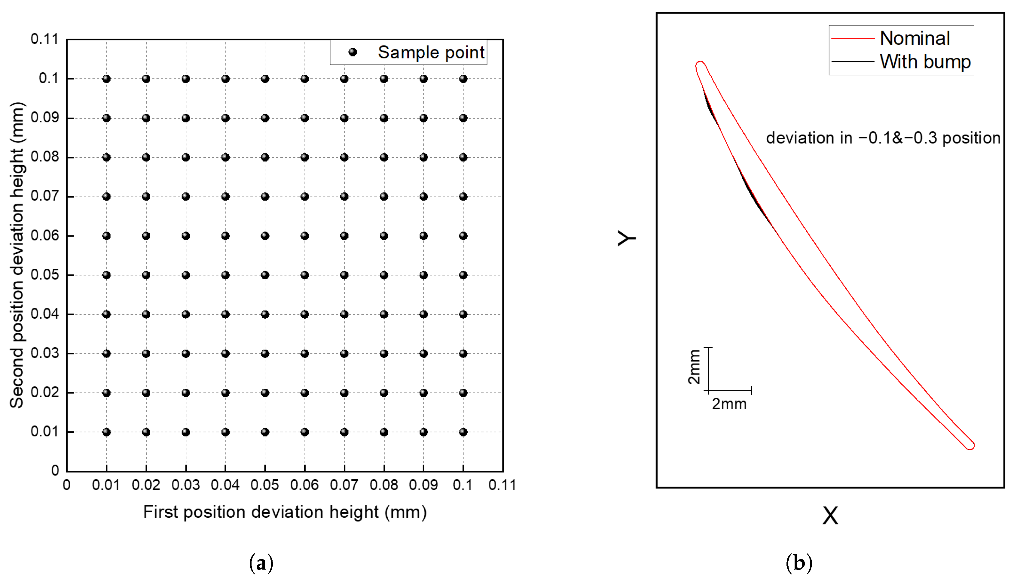
To directly study the aerodynamic performance influence of the coexisting multi-position deviations, the one-factor-at-a-time method of DOE was used for sampling. Figure 2 shows a set of sample points and the corresponding blade profiles with local geometric deviations in −0.1 and −0.3 positions. The MISES (Multiple blade Interacting Streamtube Euler Solver) program developed by MIT was used to solve the aerodynamic performance numerically. Because of good calculation reliability and fast solving speed, it has been widely used to acquire aerodynamic performance of blade with geometric deviations [8,15]. The MISES calculation results and experimental data have been compared in the subsonic and transonic compressor flow condition to ensure the calculation accuracy. Table 2 shows the grid settings in MISES program. In this study, the profile loss ω was defined in Equation (1), and the incidence range was defined as the condition at which the loss was 1.5 times the minimum value [8].
ω = p 1 * p 2 * p 1 * p 1
where p 1 * is the inlet total pressure, p 2 * is the outlet total pressure and p 1 is the inlet static pressure.

3. Results and Analysis

Currently, most researchers focus on the aerodynamic sensitivity of a single-position or a single-modal deviation, and the influence of other coexisting deviations have not been considered enough. The following analyses focus on analyzing the difference between the performance influence of two deviations coexisting and the influence sum of two deviations existing separately. Through analyzing the fluid mechanism, the coupled effect model was created to estimate the blade performance when two deviations coexist. For the convenience of description, the coexisting condition is defined as the condition where two deviations in different positions exist on the blade surface simultaneously, and the separated condition is defined as the condition where only single deviation exist on the blade surface. In addition, the sum of the separated condition means adding the aerodynamic influences of two deviations when they exist separately.

3.1. Analysis of Blade Performance and Model Establishment

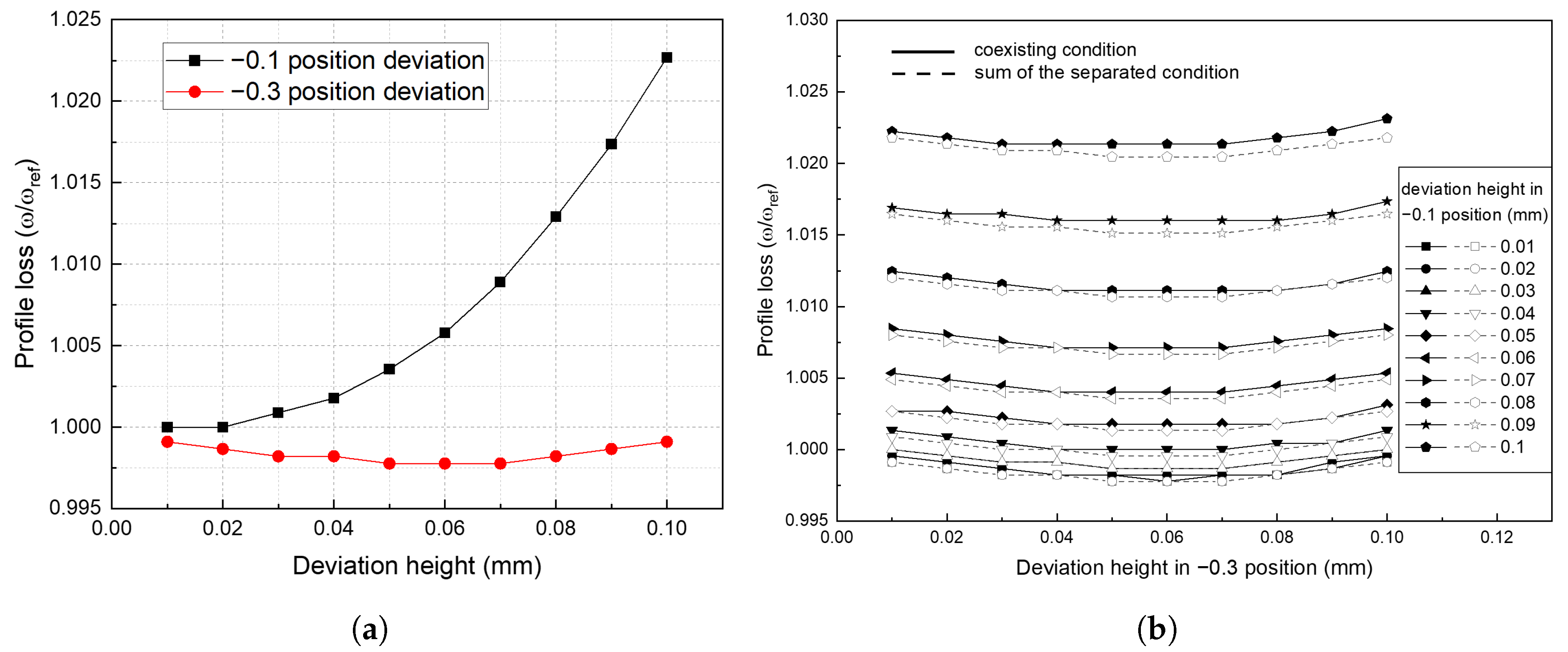
To analyze the performance influence of two-position deviations, the deviations in the −0.1 and −0.3 normalized position were first studied. The minimum profile loss coefficient, the positive incidence range and the negative incidence range were solved on the separated condition and coexisting condition. Figure 3a shows the change of profile loss on the separated condition. It can be seen that when the geometric deviation is in −0.1 position, the profile loss increases more than when it is in the −0.3 position. This result is consistent with the research conclusions on the aerodynamically sensitive area of the compressor blade [15]. While the blade loss is slightly reduced when the deviation is in −0.3 position, this is related to the actual blade profile design. Figure 3b shows the comparison of profile loss between the sum of the separated condition and the coexisting condition. It can be seen that the two results have slight differences. The profile loss of the coexisting condition is higher than the sum of the separated condition.
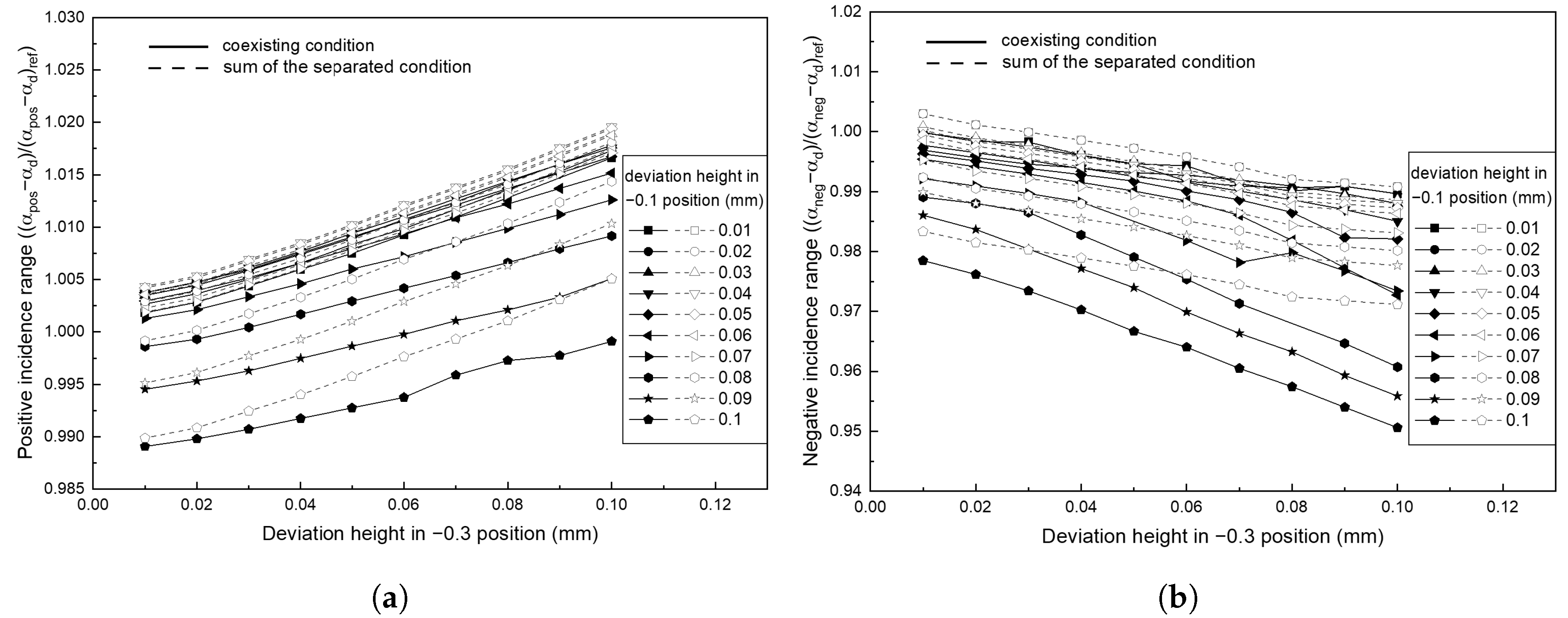
Figure 4 is a comparison of incidence range between the sum of the separated condition and the coexisting condition. In both figures, it can be clearly observed that there will be an obvious error in estimating the incidence range of the coexisting condition by simply adding the influences of the separated condition. From Figure 4a, it can be seen that the slope of the solid line is smaller than the slope of the dotted line, which means the influence of the deviation in the −0.3 position is weakened when there is a deviation in the −0.1 position. Furthermore, this weakened effect becomes obvious when the deviation height in −0.1 position increases. From Figure 4b, it can be observed that the influence of the deviation in the −0.3 position is enhanced when there is a deviation in the −0.1 position. In order to analyze the reasons for this phenomenon, Figure 5 shows the development of the boundary layer when the heights of the deviation are both 0.1mm. The reason of selecting this deviation height for analysis is to observe the obvious changes in the boundary layer. It can be seen from Figure 5, for the suction surface, the momentum thickness of the boundary layer under the positive incidence limit is much thicker than the momentum thickness under the negative incidence limit. Simultaneously, the transition position changed a lot in two different incidence limit states. The transition position of the boundary layer under the positive incidence limit is about 0.07. However, it changes to 0.17 under the negative incidence limit, which is a position between the two deviations.
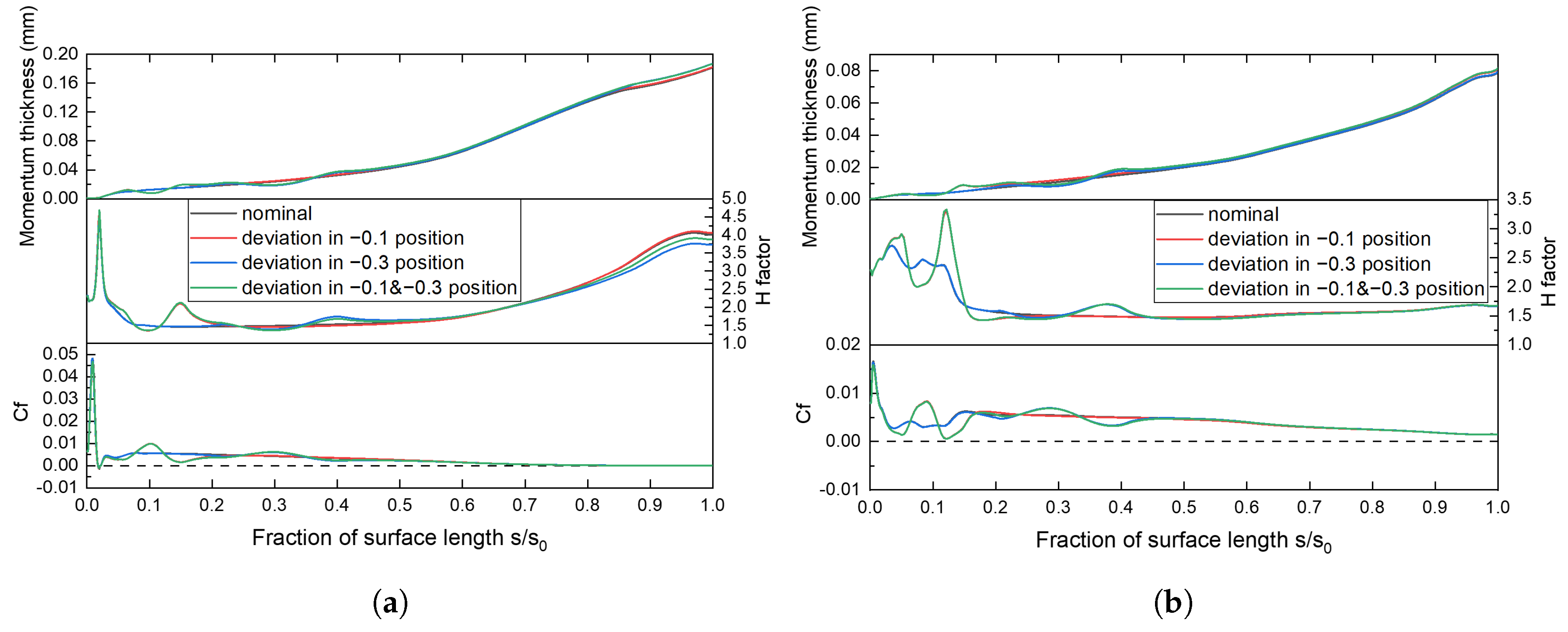
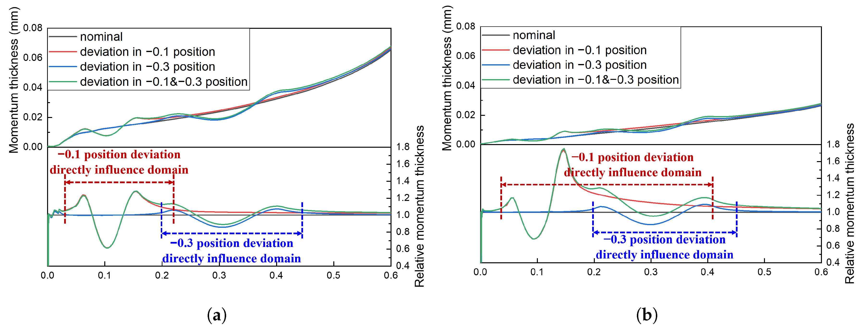
To analyze the deviation’s effect on the surface boundary layer in more detail, Figure 6 shows the momentum thickness and relative momentum thickness of the suction surface boundary layer from the 0 position to the 0.6 position. The relative momentum thickness was obtained by dividing the momentum thickness of the blade on the separated condition by the momentum thickness of the nominal blade. The region where the relative momentum thickness changes drastically is defined as the direct influence domain of the single deviation. In Figure 6a, the direct influence domains of deviations in the −0.1 position and −0.3 position are not overlapped a lot. Therefore, it can be considered that the deviation in the −0.1 position has no other influence on the development of the boundary layer in the −0.3 position except changing its upstream boundary layer thickness. Figure 6b shows that due to the thin boundary layer thickness and the close transition position, the direct influence domain of the deviation in the −0.1 position will cover a long blade surface length. Furthermore, the wide direct influence domain means the coupled effect of −0.1 position deviation and −0.3 position deviation is very complex.
Through the above analysis of the blade aerodynamic performance and the development of the boundary layer, it can be found that when the boundary layer of the incoming flow is thick enough, the influence of the downstream deviation is weakened. It is also clearly that as the height of the upstream deviation increases, the thickness of the downstream boundary layer after this deviation increases significantly. The degree of the weakening effect should be affected by the relative heights of the two deviations and the boundary layer. In addition, obviously, when the two deviations are very close, their coupled effect will be much larger than the effect when they are far away. So the distance between the two deviations will also affect this weakening effect. Therefore, considering the meaning of the exponential function, the coupled effect model on the positive incidence range, shown in Equation (2), can be constructed.
Δ X 1 & X 2 r a n g e = Δ X 1 r a n g e + [ e k Δ S · h X 1 / θ X 1 h X 2 / θ X 2 ] · Δ X 2 r a n g e
where X 1 is the upstream deviation relative to the airflow, X 2 is the downstream deviation relative to the airflow, Δ X r a n g e is the change of the positive incidence range caused by the deviation in the X position, Δ S is the normalized distance between the two deviations in the different positions, h X / θ X is the ratio of the deviation height in the X position to the momentum thickness of the boundary layer on the nominal blade, and k is an undetermined coefficient (related to profile shape, flow state, etc.). The k value can be obtained by the least square method. This model assumes that the weakening effect of the downstream deviation is exponential. In addition, it considers the deviation height, the boundary layer thickness and the distance between the two deviations. Moreover, when the distance between the two deviations is 0, the model degenerates to a simple sum of the two deviations influences, which is consistent with the real situation.

3.2. Model Verification

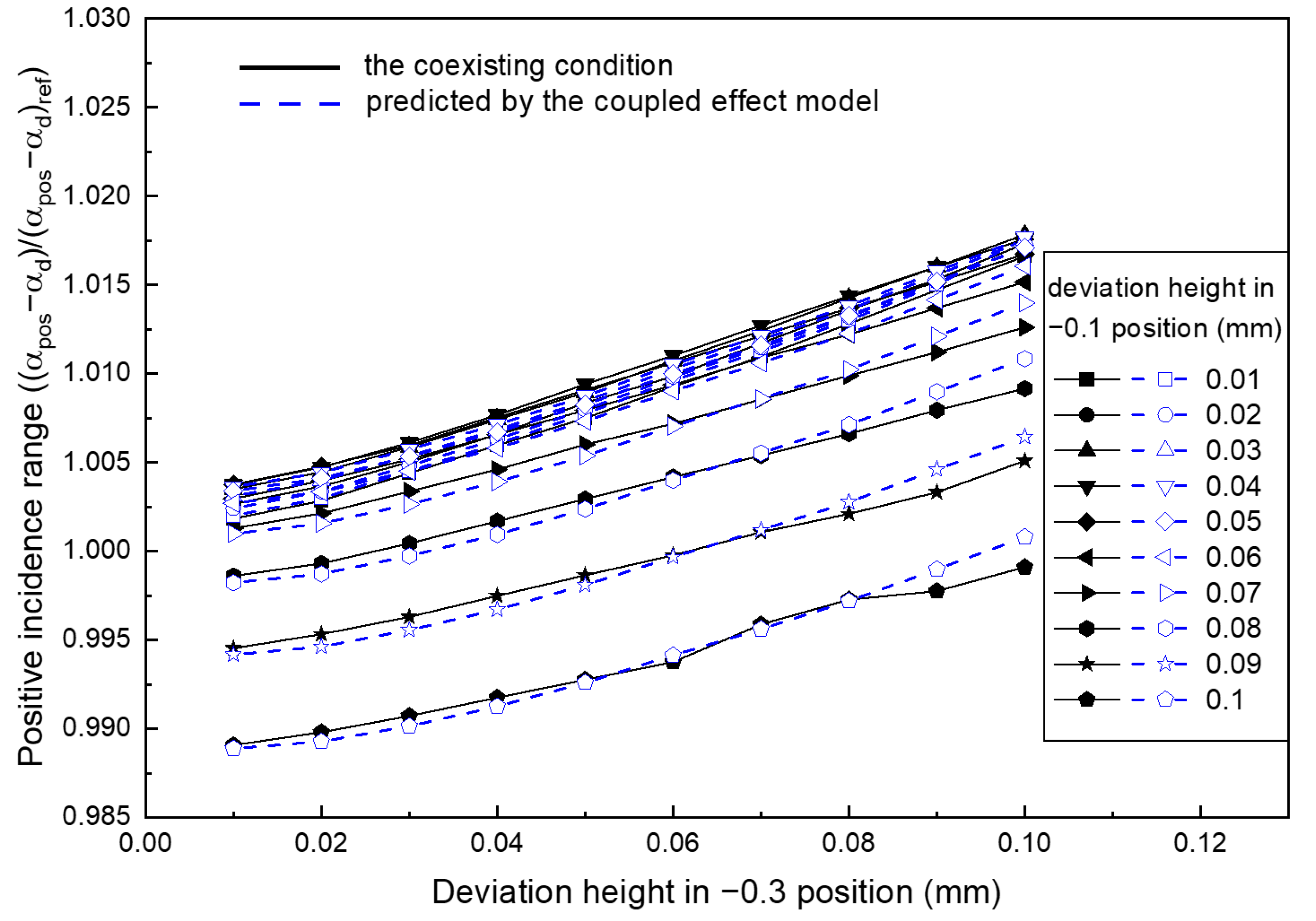
The model focus on expressing the weakening effect of the downstream deviation when the boundary layer of the incoming flow is thick. Therefore, the following verification was carried out for the positive incidence range when the deviations were on the suction surface. On this condition, the boundary layer is thick in the deviation positions. The coupled effect model was verified in the case discussed above firstly. Figure 7 shows the comparison between the performance calculated by the coupled effect model and the performance of the coexisting condition, where the value of k is 0.8074 determined by the least square method. It can be seen that the coincidence of the two results is very high, which means the coupled effect model accurately predicts the positive incidence range of the coexisting condition.
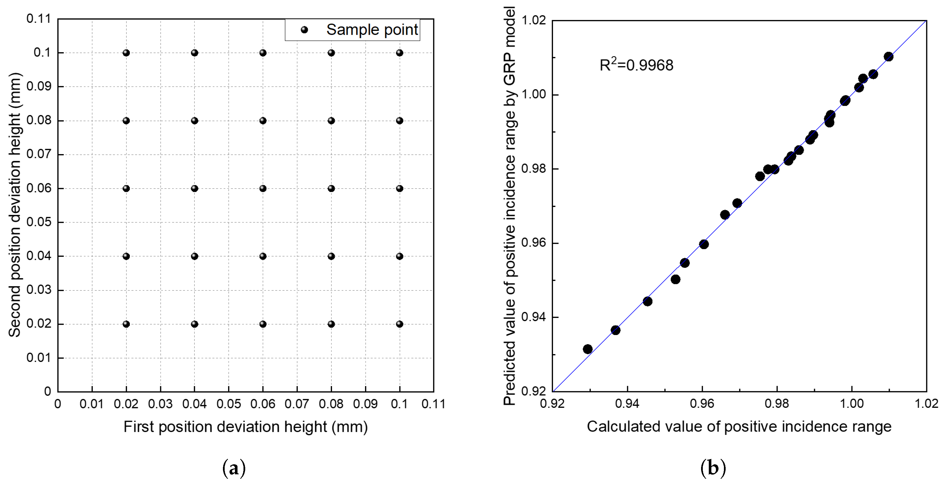
To verify the accuracy of the coupled effect model further, the aerodynamic performances of the blade with the geometric deviations in the −0.3 position and the −0.5 position were analyzed. The cost of massive high-precision numerical simulations is huge. To reduce the computational cost, the Gaussian Process Regression (GPR) was used to make a surrogate model. In addition, the results obtained by the coupled effect model were compared with the results obtained by the high-precision surrogate model to verify its accuracy. The research of Nair et al. [17] shows that the GPR model can provide enough flexibility for modelling the nonlinear functions. Figure 8a shows the sample points obtained by one-factor-at-a-time method of DOE. Figure 8b shows the accuracy of the surrogate model by using the leave-one-out method. The regression coefficient for a linear model fit to the leave-one-out results is R 2 > 0.99. Therefore, it can be considered that the surrogate model obtained by the GPR method is accurate, thereby the accuracy of the benchmark to verify the coupled effect model is ensured.
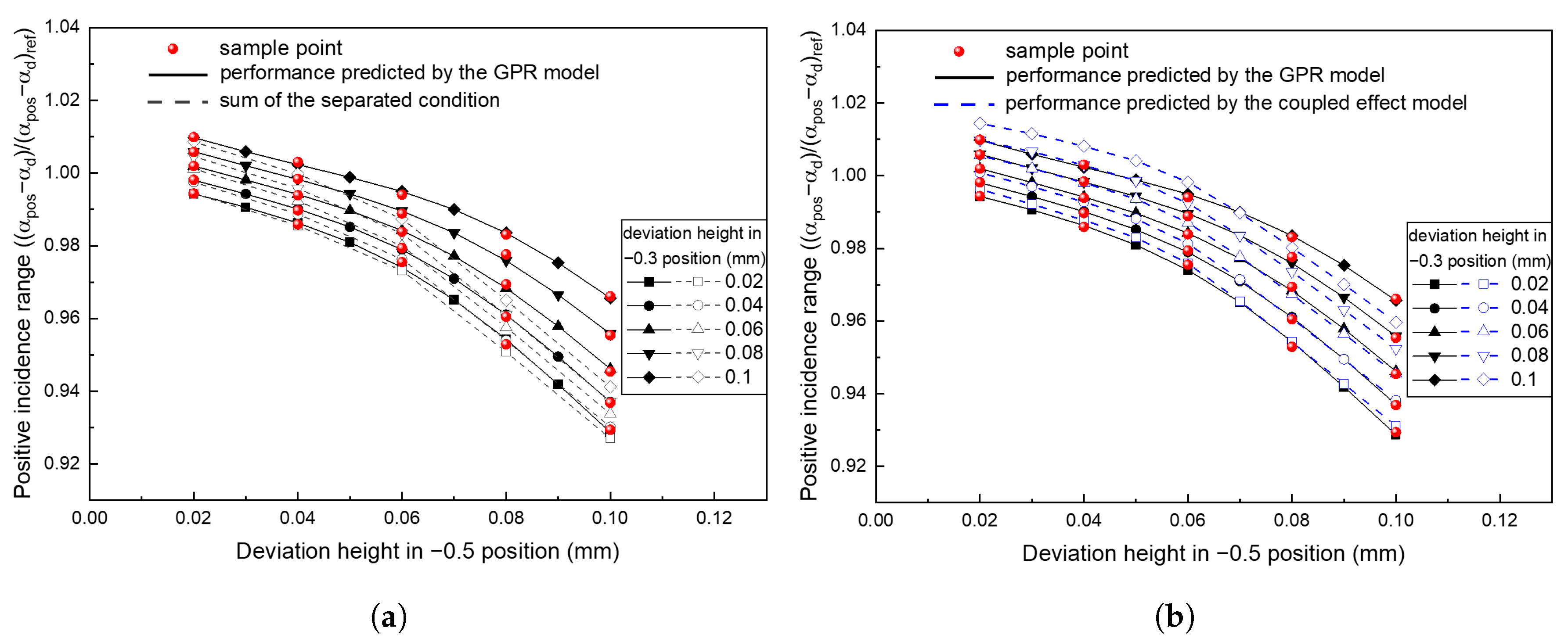
Figure 9 compares the positive incidence range obtained by different method. It can be seen that the dotted line in Figure 9b is more consistent with the solid line than the dotted line in Figure 9a. So the coupled effect model can better predicts the positive incidence range than the sum of the separated condition. Therefore, the model has sufficient accuracy to be used in the performance evaluation of the blade with two-position deviation.

4. Discussion and Conclusions

This paper analyzes the aerodynamic performance of the blade profile with two-position local geometric deviations and explores the mechanism of the aerodynamic influence causing by the deviations. Through analyzing the factors which affect the aerodynamic performance on the coexisting condition, the coupled effect model was created to estimate the performance of the blade profile. Conclusions can be drawn as follows:
  • The aerodynamic performance influences of the blade local geometric deviations in different positions are not isolated from each other. In addition, there is a big difference in the incidence range between the sum of the separated condition and the coexisting condition. When solving the aerodynamic sensitivity of the blade profile, the impact of deviations in other positions should also be considered.
  • The coupled effect between deviations is related to the deviation heights, the thickness of the boundary layer and the distance between the deviations. When the upstream boundary layer thickens, the effect of the downstream deviation will be weakened.
  • By introducing the condition of a thick boundary layer and the assumption of exponential weakening effect, the coupled effect model was created to model the weakening effect of the downstream deviation. The accuracy of the model is proven by predicting the positive incidence range when the deviations are located on the suction surface. This model provides a new approach for the performance evaluation of the blade profile with multi-position deviations.

Author Contributions

Conceptualization, X.Y. and M.L.; methodology, X.Y. and M.L.; investigation, X.Y. and M.L.; writing—original draft preparation, M.L.; writing—review and editing, X.Y. and M.L.; supervision, B.L., X.Y. and G.A. All authors have read and agreed to the published version of the manuscript.

Funding

This work was supported by National Natural Science Foundation of China (Grant Nos. 51806004, 51790511) and National Science and Technology Major Project (Grant No. 2017-II-0001-0013).

Acknowledgments

Thanks to Jiaxin Liu for providing the blade deviation generator. And thanks to Jiaqi Liu and Letian Zhang for their precious suggestions on the concept expression.

Conflicts of Interest

The authors declare no conflict of interest.

Abbreviations

The following abbreviations are used in this manuscript:
M a i n Inlet Mach number
R e Reynolds number
T u Turbulivity
ω Total pressure loss coeffcient
α Flow angle measured from axial
θ Momentum thickness of boundary layer
HShape factor
C f Blade surface friction coefficient
sSurface distance from leading-edge
s 0 Total surface length

References

  1. Klapproth, J.F. Approximate Relative-Total-Pressure Losses of An Infinite Cascade of Supersonic Blades with Finite Leading-Edge Thickness; NASA: Washington, DC, USA, 1950.
  2. Reid, L.; Urasek, D. Experimental Evaluation of the Effects of a Blunt Leading Edge on the Performance of a Transonic Rotor. J. Eng. Power 1973, 95, 199. [Google Scholar] [CrossRef]
  3. Suder, K.L.; Chima, R.V.; Strazisar, A.J.; Roberts, W.B. The Effect of Adding Roughness and Thickness to a Transonic Axial Compressor Rotor. J. Turbomach. 1995, 117. [Google Scholar] [CrossRef] [Green Version]
  4. Garzon, V.; Darmofal, D. Using computational fluid dynamics in probabilistic engineering design. In Proceedings of the 15th AIAA Computational Fluid Dynamics Conference, Anaheim, CA, USA, 11–14 June 2001; p. 2526. [Google Scholar]
  5. Garzon, V.E. Probabilistic Aerothermal Design of Compressor Airfoils. Ph.D. Thesis, Massachusetts Institute of Technology, Cambridge, MA, USA, 2003. [Google Scholar]
  6. Lamb, C.M. Probabilistic Performance-Based Geometric Tolerancing of Compressor Blades. Ph.D. Thesis, Massachusetts Institute of Technology, Cambridge, MA, USA, 2005. [Google Scholar]
  7. Goodhand, M.N.; Miller, R.J. Compressor leading edge spikes: A new performance criterion. J. Turbomach. 2011, 133, 021006. [Google Scholar] [CrossRef]
  8. Goodhand, M.N.; Miller, R.J.; Lung, H.W. The sensitivity of 2D compressor incidence range to in-service geometric variation. In Proceedings of the ASME Turbo Expo 2012: Power for Land, Sea, and Air, Copenhagen, Denmark, 11–15 June 2012; pp. 159–170. [Google Scholar]
  9. Goodhand, M.N.; Miller, R.J.; Lung, H.W. The impact of geometric variation on compressor two-dimensional incidence range. J. Turbomach. 2015, 137, 021007. [Google Scholar] [CrossRef]
  10. Dow, E.A. Robust Design and Tolerancing of Compressor Blades. Ph.D. Thesis, Massachusetts Institute of Technology, Cambridge, MA, USA, 2015. [Google Scholar]
  11. Liu, B.; Liu, J.; Yu, X.; Meng, D. Influence mechanisms of manufacture variations on supersonic/transonic blade aerodynamic performances. In Proceedings of the ASME 2020: Turbomachinery Technical Conference and Exposition, London, UK, 22–26 June 2020; pp. 2020–15485. [Google Scholar]
  12. Lange, A.; Voigt, M.; Vogeler, K.; Johann, E. Principal component analysis on 3D scanned compressor blades for probabilistic CFD simulation. In Proceedings of the 53rd AIAA/ASME/ASCE/AHS/ASC Structures, Structural Dynamics and Materials Conference 20th AIAA/ASME/AHS Adaptive Structures Conference 14th AIAA, Honolulu, HI, USA, 23–26 April 2012; p. 1762. [Google Scholar]
  13. Tang, X.; Luo, J.; Liu, F. Adjoint aerodynamic optimization of a transonic fan rotor blade with a localized two-level mesh deformation method. Aerosp. Sci. Technol. 2018, 72, 267–277. [Google Scholar] [CrossRef]
  14. Wunsch, D.; Hirsch, C.; Nigro, R.; Coussement, G. Quantification of combined operational and geometrical uncertainties in turbo-machinery design. In Proceedings of the ASME Turbo Expo 2015: Power for Land, Sea, and Air, Montreal, QC, Canada, 15–19 June 2015; p. V02CT45A018. [Google Scholar]
  15. Dow, E.A.; Wang, Q. Simultaneous robust design and tolerancing of compressor blades. In Proceedings of the ASME Turbo Expo 2014: Power for Land, Sea, and Air, Düsseldorf, Germany, 16–20 June 2014; p. V02BT45A007. [Google Scholar]
  16. Hicks, R.M.; Henne, P.A. Wing design by numerical optimization. J. Aircr. 1978, 15, 407–412. [Google Scholar] [CrossRef]
  17. Nair, P.; Choudhury, A.; Keane, A. A Bayesian framework for uncertainty analysis using deterministic black-box simulation codes. In Proceedings of the 42nd AIAA/ASME/ASCE/AHS/ASC Structures, Seattle, WA, USA, 16–19 April 2001; p. 1677. [Google Scholar]
Figure 1. Definition of the representative position points on blade surface.
Applsci 10 08976 g001
Figure 2. Sampling results when the local geometric deviations are in the −0.1 and −0.3 positions.(a) Sample points obtained by the DOE method. (b) Balde profile with deviations corresponding to the sample point.
Applsci 10 08976 g002
Figure 3. Analysis of the minimum profile loss coefficient. (a) Profile loss of the separated condition. (b) Comparison of the profile loss between the sum of the separated condition and the coexisting conditiong.
Applsci 10 08976 g003
Figure 4. Analysis of the incidence range. (a) Comparison of the positive incidence range between the sum of the separated condition and the coexisting condition. (b) Comparison of the negative incidence range between the sum of the separated condition and the coexisting condition.
Applsci 10 08976 g004
Figure 5. Development of the boundary layer on the suction surface. (a) Analysis of the boundary layer when the incidence is under the positive incidence limit. (b) Analysis of the boundary layer when the incidence is under the negative incidence limit.
Applsci 10 08976 g005
Figure 6. Analysis of the boundary layer from the 0 position to the 0.6 position. (a) Detailed analysis of the boundary layer when the incidence is under the positive incidence limit. (b) Detailed analysis of the boundary layer when the incidence is under the negative incidence limit.
Applsci 10 08976 g006
Figure 7. Comparison between the positive incidence range calculated by the coupled effect model and the positive incidence range of the coexisting condition.
Applsci 10 08976 g007
Figure 8. Sample points and the leave-one-out test of the surrogate model. (a) Sample points when the deviations is in the −0.3 position and −0.5 position. (b) Using the leave-one-out method to verify the accuracy of the surrogate model.
Applsci 10 08976 g008
Figure 9. Model verification with the deviations in the −0.3 position and −0.5 position. (a) Comparison between the positive incidence range predicted by the GPR model on the coexisting condition and the sum of the positive incidence range on the separated condition. (b) Comparison between the positive incidence range predicted by the GPR model and the positive incidence range predicted by the coupled effect model on the coexisting condition.
Applsci 10 08976 g009
Table 1. Parameterized sample space of the profile deviations.
Deviation PositionParameterMin/(mm)Max/(mm)Sample Interval/(mm)
Leading edgeHeight0.010.10.01
Width10% Chord length
Profile bodyHeight0.010.10.01
Width20% Chord length
Table 2. MISES grid parameters.
ParameterValue
Local/average spacing ratios in leading edge0.1
Local/average spacing ratios in trailing edge0.9
Inlet and outlet grid typeH-type
Number of inlet points50
Number of outlet points30
Number of streamlines20
Publisher’s Note: MDPI stays neutral with regard to jurisdictional claims in published maps and institutional affiliations.