Article

The Enhanced Mechanism of 0.05 wt. % Nd Addition on High Temperature Reliability of Sn-3.8Ag-0.7Cu/Cu Solder Joint

1
School of Materials Science and Engineering, Nanjing University of Science and Technology, Nanjing 210094, China
2
State Key Laboratory of Advanced Welding and Joining, Harbin Institute of Technology, Harbin 150001, China
3
State Key Laboratory of Advanced Brazing Filler Metals and Technology, China Innovation Academy of Intelligent Equipment Co., Ltd., NingBo 315700, China
*
Author to whom correspondence should be addressed.
Appl. Sci. 2020, 10(24), 8935; https://doi.org/10.3390/app10248935
Submission received: 25 November 2020 / Revised: 11 December 2020 / Accepted: 13 December 2020 / Published: 15 December 2020
(This article belongs to the Section Materials Science and Engineering)

Abstract

:
In this study, the effect of appropriate Nd addition on improving the high-temperature reliability of Sn-3.8Ag-0.7Cu (SAC387)/Cu solder joint after aging treatment was investigated. The interfacial microstructure of solder joint was refined with proper addition of Nd. This phenomenon could be explained as the adsorbing-hindering effect of surface-active Nd atoms which blocked the growth of brittle intermetallic compounds (IMCs) in the solder joint. Theoretical analysis indicated that 0.05 wt. % addition of Nd could distinctly decrease the growth constant of Cu6Sn5 IMCs and slightly decrease the growth constant of Cu3Sn IMCs respectively. The shear force of SAC387-0.05Nd/Cu solder joint was evidently improved compared with the origin solder joint. In addition, SAC387-0.05Nd/Cu solder joint maintained excellent mechanical property compared with SAC387/Cu solder joint even after 1440 h aging treatment.

1. Introduction

With the development of miniaturization in electronic packaging, the requirements of high reliability solder joint have attracted increasing attention [1,2]. Owing to the importance of reliable connection between electronic component and conductive substrates, the joint should provide suitable mechanical, electrical and thermal properties to achieve the functions of electronic devices.
Nowadays, under the pressure of WEEE and RoHS directives, solder used in certain electronic devices should be lead-free series (Sn-Ag-Cu, Sn-Zn, Sn-Cu, etc.) instead of Sn-Pb solder [3,4,5]. Among all the lead-free solders, Sn-Ag-Cu eutectic lead-free solder was widely accepted due to its excellent comprehensive properties [6]. However, bulk Ag3Sn intermetallic compounds (IMCs) in the solder matrix and excessive growth of interfacial IMCs in Sn-Ag-Cu solder joint after aging treatment have been proved to be a severe mechanical degradation issue [7]. To solve the problem and improve the high temperature reliability of solder joint, researchers have found that micro-alloying including Ni, In, Bi, rare earth (RE) elements and nanoparticles could have a positive influence on the microstructure of solder joint [8,9,10]. However, although doping nanoparticles has become the research hotspot, the doping technology and agglomeration phenomenon are difficult to further improve [11,12]. Therefore, micro-alloying with trace amount of proper element could be more effective.
It has been reported that the RE elements with high chemical activity could have beneficial impacts on refining the microstructure of solder as well as inhibiting the growth of interfacial IMCs [13,14]. Sadiq et al. [15] added trace amount of RE La into Sn-Ag-Cu alloy and investigated its high-temperature reliability (150 °C). The results showed that the tensile strength of La-doped solder joint was 20 % higher than the pure one. In addition, La-doped solder witnessed the size of IMCs decreased by 40 %, and the coarsening rate of IMCs was slowed by 70% compared with the origin Sn-Ag-Cu solder. Gao et al. [16] found that adding trace addition of Nd into SAC387 could hinder the growth of IMCs but excess addition of Nd may have unfavorable effects on the mechanical properties of as-soldered joint.
In this study, the effect of appropriate Nd addition on long term high temperature reliability of Sn-3.8Ag-0.7Cu solder joint was investigated. The mechanical property and interfacial microstructure of solder joint after long term aging treatment was obtained. In addition, the effect of Nd addition on growth kinetics of interfacial IMCs during aging was evaluated.

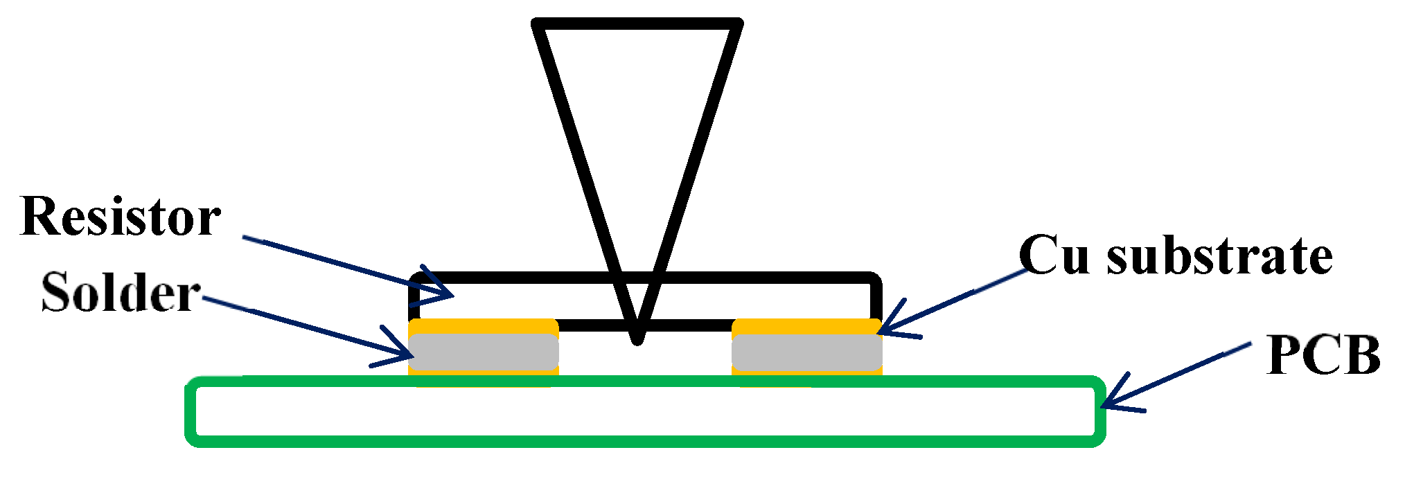
2. Experimental Part

Sn, Ag, and Cu with purity of 99.95 wt. % were melt at 900 °C ± 10 °C in a vacuum furnace (MZG-0.5, Chengdu Jituo Instrument Equipment Co., Ltd., Chendu, China) firstly to obtain the SAC387 solder. Then, Nd was added into the molten SAC387 solder in the form of Sn-10Nd alloy to avoid the loss of Nd, and the furnace temperature at this time was adjusted to 550 ± 1 °C. Based on the previous researches [16], the addition of Nd was adjusted to be 0.05 wt. %. Finally, the molten alloy was cast into small bars and pieces in air for experimental use.
Corresponding solder pieces (SAC387; SAC387-0.05Nd) were soldered on Cu substrate in an automatic reflow furnace (T-962, Shenzhen Bangqi Chuangyuan Technology Co., Ltd., Shenzhen, China) to fabricate the solder joint specimens [17]. For interfacial microstructure observation, specimens were cross-sectioned perpendicularly to the solder/Cu interface. Aging treatment was carried out according to the standards of Department of Defense of the USA (MIL-STD-883) and IPC-Association Connecting Electronics Industries (IPC-SM-785) [18]; the aging temperature was set as 150 °C, and the aging time was extended to 1400 h (h). All samples were polished with 0.3 μm Al2O3 powder and then etched by 4% HNO3-alcohol for microstructure observation. The scanning electron microscope (SEM) with Energy-dispersive X-ray spectroscopy (EDS) (S-3000N/H, Hitachi Co., Ltd., Japan) was used to analyze the microstructure of solder joint.
The shear force of solder joint was tested through micro-joint strength tester (STR-1000, Hitachi Co., Ltd., Tokyo, Japan) as shown in Figure 1. The shear samples were made by soldering 0805 ceramic resistors on printed circuit board (PCB) attached with Cu pad. Each shear test was repeated five times, and the average value was saved as the final result, and the fractograph of joint was studied through SEM.

3. Results and Discussion

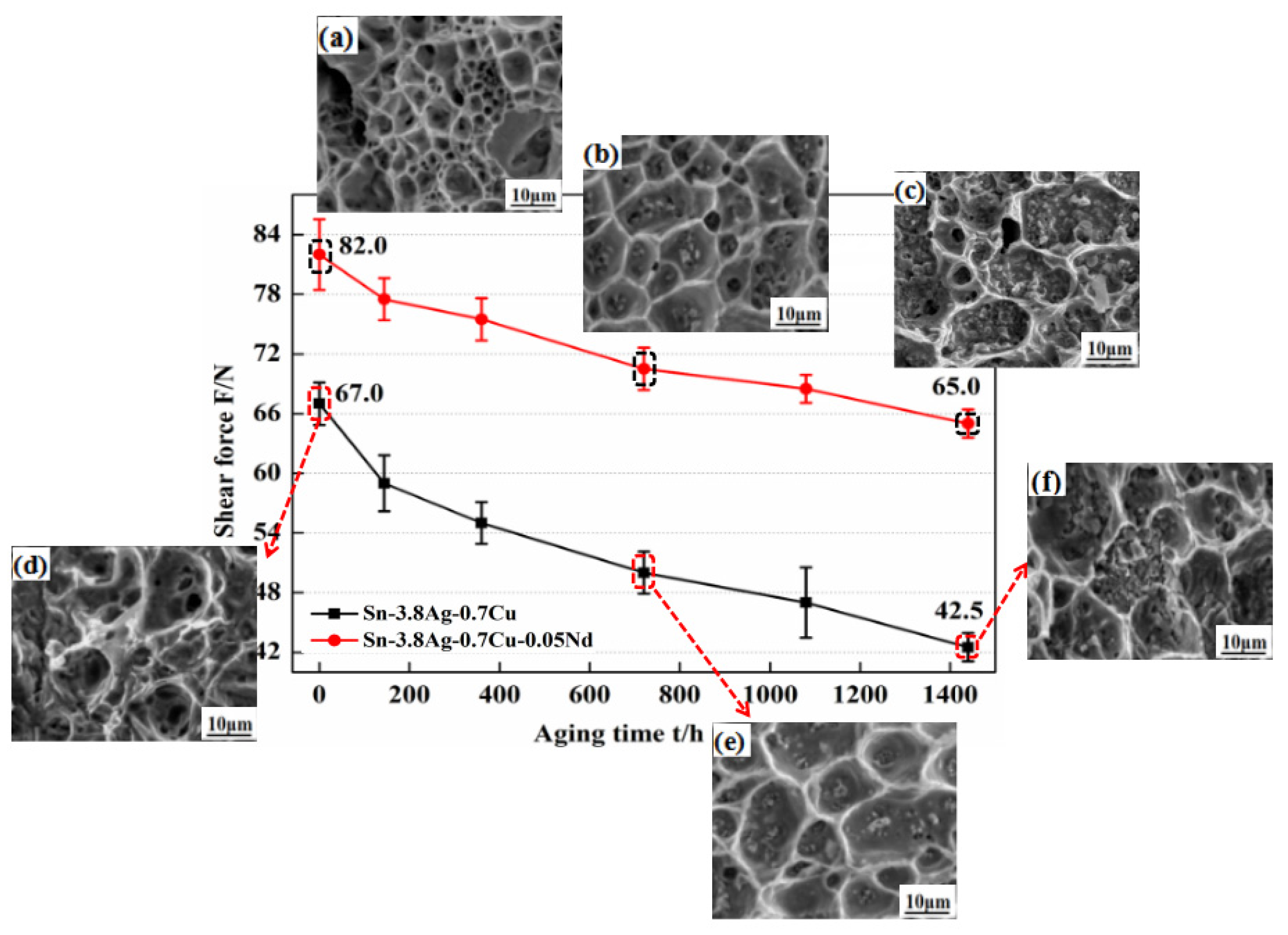
3.1. Shear Force and Fracture Morphology after Aging Treatment

The shear force of SAC387-0.05Nd/Cu joints during aging treatment with SEM image of fracture morphologies were shown in Figure 2. It can be seen that the shear force of solder joint decreased with the aging process, while, the shear force of SAC387-0.05Nd/Cu solder joint maintained higher performance compared with SAC387/Cu solder joint. Moreover, the shear force of SAC387/Cu solder joint was decreased about 36.6% after 1400 h aging time, while that of SAC387-0.05Nd/Cu solder joint was about 20.7%. It can be concluded that the shear force decreasing rate of solder joint after long-term aging treatment was obviously reduced by the appropriate addition of element Nd.
From the fracture morphology of solder joint in Figure 2a–f, it can be clearly seen that dimples with various sizes were emerged on the fracture surfaces of solder joint without aging treatment, indicative of a distinct ductile fracture mode for both SAC387/Cu (Figure 2a) and SAC387-0.05Nd/Cu solder joints (Figure 2d).
It should be noted that during the whole aging process, the average size of dimples on the fracture surface in SAC387-0.05Nd/Cu solder joint (Figure 2b, ~7.2 μm; Figure 2c, ~9.8 μm) were lower than those on the fracture surface of SAC387/Cu solder joint (Figure 2e, 10.1 μm; Figure 2f, 15.2 μm). In addition, IMCs in the dimples of both kinds of joints emerged with aging extended (Figure 2c,f), which was probably caused by the growth of interfacial IMCs.

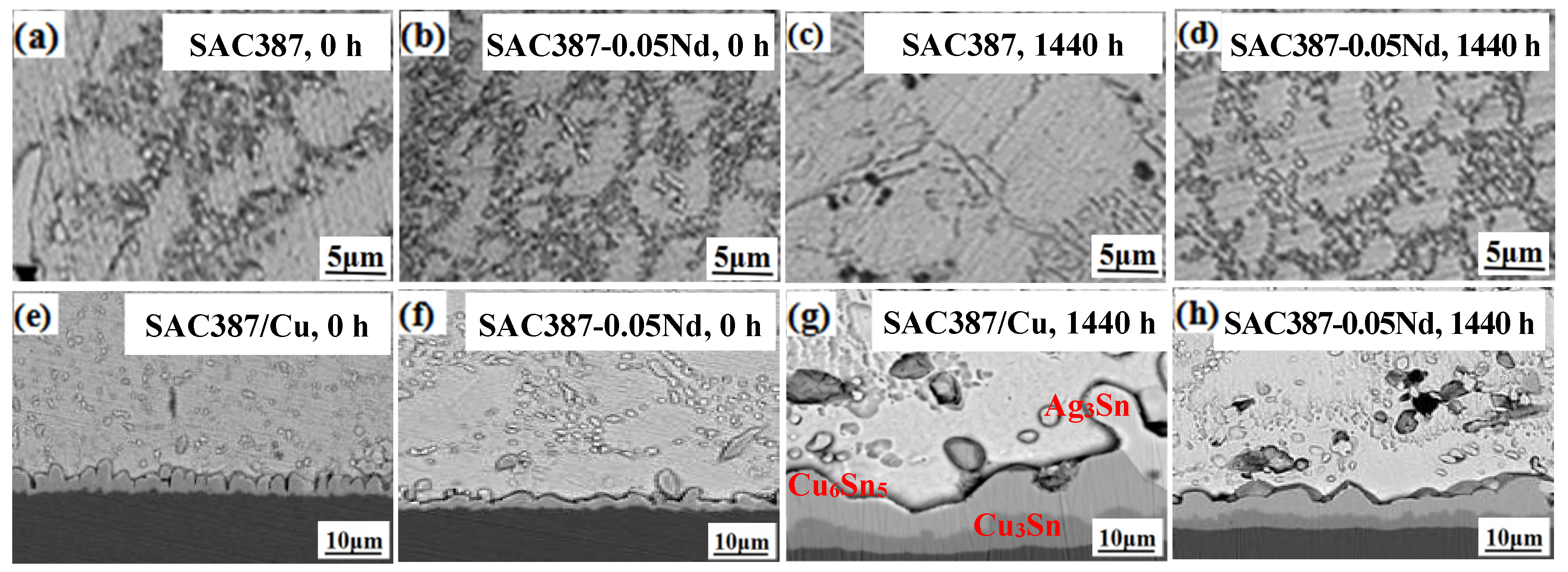
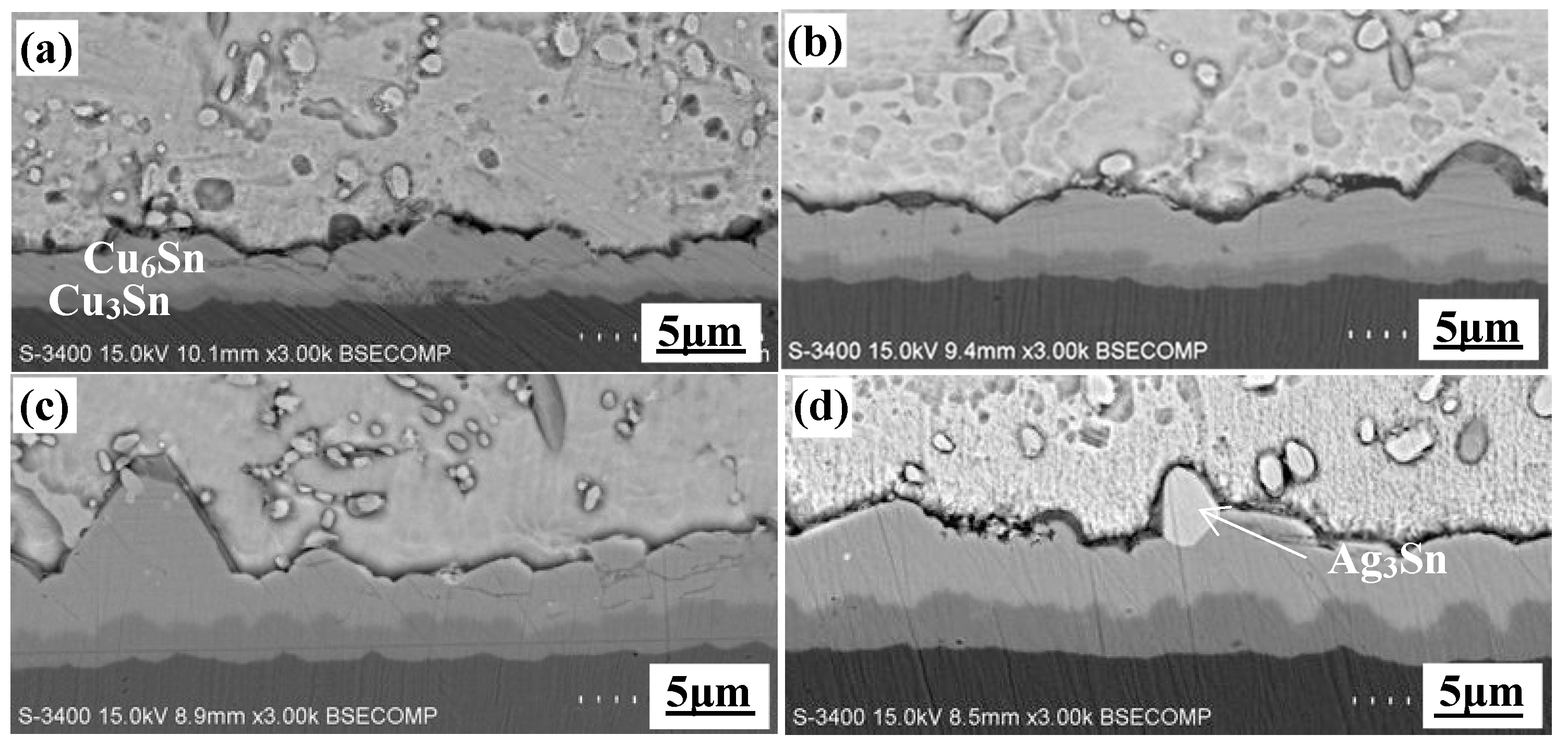
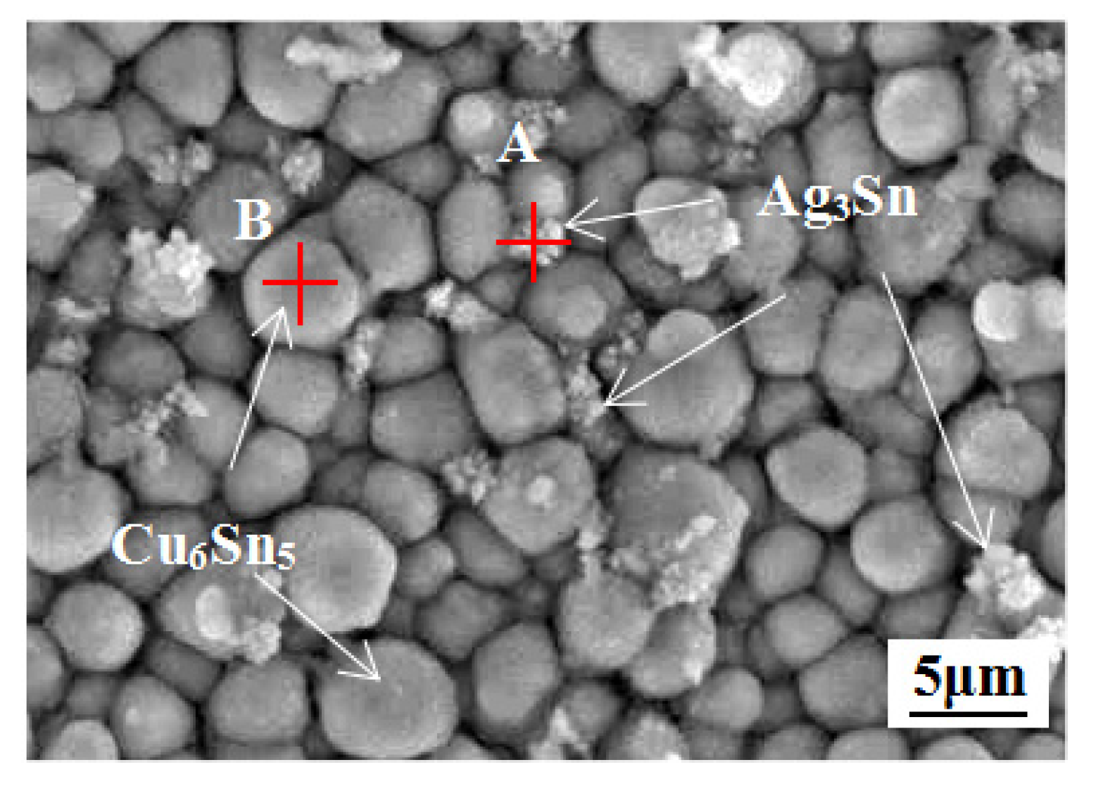
3.2. Microstructure Evolution during Aging

Figure 3 shows the microstructure of as-soldered and -aged (up to 1440 h) solder matrix and joint. It can be seen that SAC387-0.05Nd solder (Figure 3b) has a better refined microstructure compared with the original (Figure 3a) SAC387 solder. In addition, the amount of eutectic areas was also increased after doping 0.05 wt. % Nd. After 1440 h aging treatment, the size of IMCs in eutectic area enlarged with aging time in both solders (Figure 3c–d). Due to the refining effect of Nd, the average size of IMCs in the aged SAC387-0.05Nd solder was obviously smaller than those in the aged SAC387 solder. Figure 3e–h shows the evolution of interfacial morphology of solder joint after aging treatment, it can be clearly observed that a continuous hill-like Cu6Sn5 interfacial IMC layer (IML) [19] with sharp protruding emerged at SAC387/Cu interface (Figure 3e). Meanwhile, the growth of interfacial IMCs was inhibited in SAC387-0.05Nd solder joint, exhibiting as flatter IMC morphology (Figure 3f). After 1440 h aging treatment, the thickness and radius of Cu6Sn5 in both solder joints increased with aging time (Figure 3g,h). It can be concluded that the thickness and radius of Cu6Sn5 at SAC387/Cu interface were larger than those at SAC387-0.05Nd/Cu interface, indicating a hindering effect of Nd on the growth of interfacial IMCs. Besides, a darker interfacial IMC layer identified as Cu3Sn was observed at the bottom of interfacial Cu6Sn5 IMC layer in both solder joints, while the thickness of Cu3Sn layer in SAC387-0.05Nd/Cu interface was less than that of SAC387/Cu interface.
Figure 4 and Figure 5 provided the detailed interfacial IMCs’ evolution of these two types of joints aged for different hours. As can be clearly seen, interfacial Cu6Sn5 and Cu3Sn IMCs grew with aging time, and those at the SAC387-0.05Nd/Cu interface grew slower compared to those at the SAC387/Cu interface. In addition, strip-shaped Ag3Sn IMCs on the top of Cu6Sn5 IMCs at SAC387/Cu interface could be clearly observed during the aging process (Figure 4). However, the size and shape of Ag3Sn IMCs was obviously reduced at SAC387-0.05Nd/Cu interface as shown in Figure 5. Thus, these Ag3Sn IMCs play an inhibiting role of the growth of interfacial IMCs to some degree, as will be given in Section 3.4.
The absorbing-refining effect of Nd during aging treatment is shown in Figure 6. Generally, the growth of IMCs in solders is dependent on the diffusion rate of Sn, Ag and Cu atoms (Figure 6a). However, element Nd is prone to be absorbed on the surface of IMCs due to its surface-active characteristic as shown in Figure 6b, which hindered the diffusion of Sn, Ag and Cu atoms [19]. As can be seen from Figure 6c, the interfacial IMCs grows depending on the diffusion of Sn and Cu atoms to the solder/Cu6Sn5, Cu6Sn5/Cu3Sn and Cu3Sn/Cu interfaces at a certain rate; hence the interfacial Cu6Sn5 IMCs are scallop-shaped. With trace amount of Nd added, the interfacial Cu6Sn5 became flatter due to the adsorbing effect of Nd atoms on the grain surface of Cu6Sn5 IMCs and hindering their growth (Figure 6d).
Figure 6e illustrated the effect of excess Nd on hindering the growth of IMCs in Sn-Zn-Nd solder joint [20]. As a result, excess Nd atoms near the interface of solder joint finally formed massive amount of Sn-Nd phase. While in SAC387-0.05Nd solder joint, appropriate Nd addition could hinder the growth of IMCs as well as avoid the formation of brittle Sn-Nd phase which may deteriorate the mechanical property of solder joint.

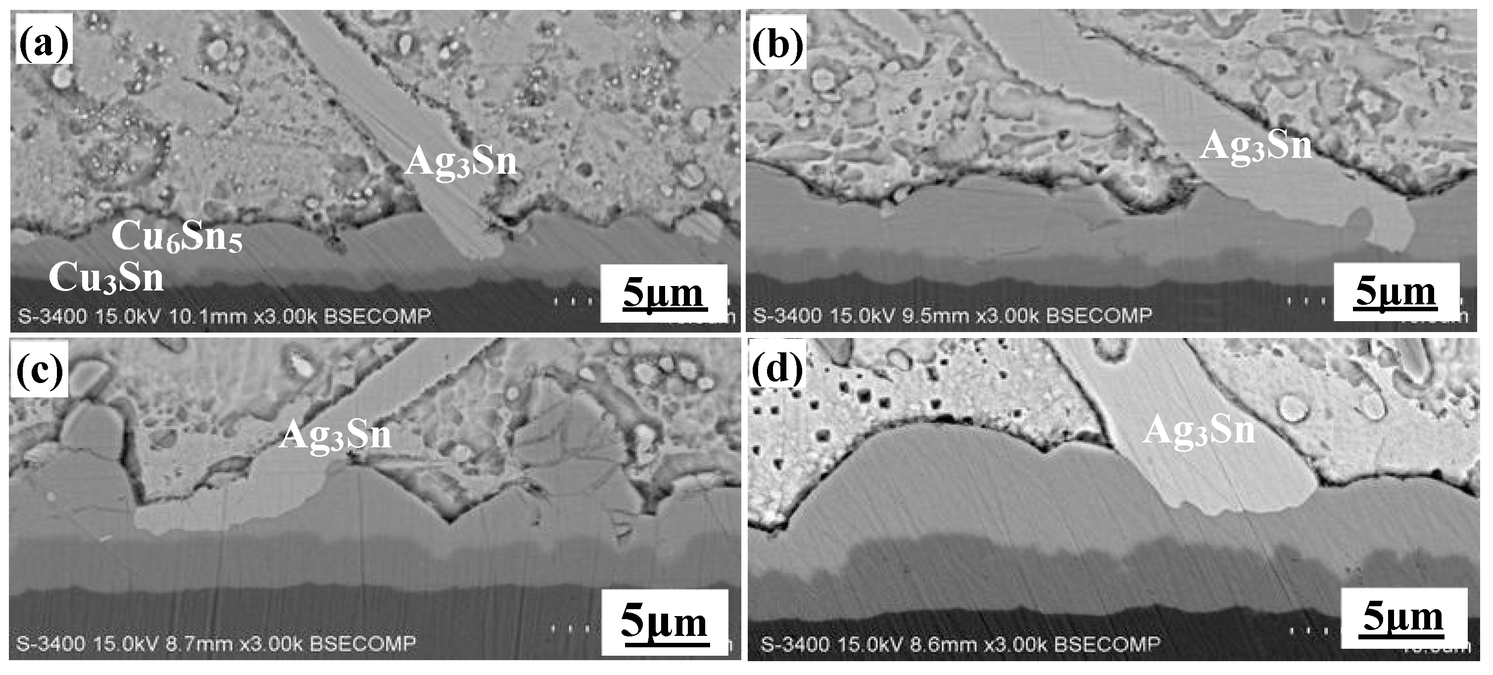
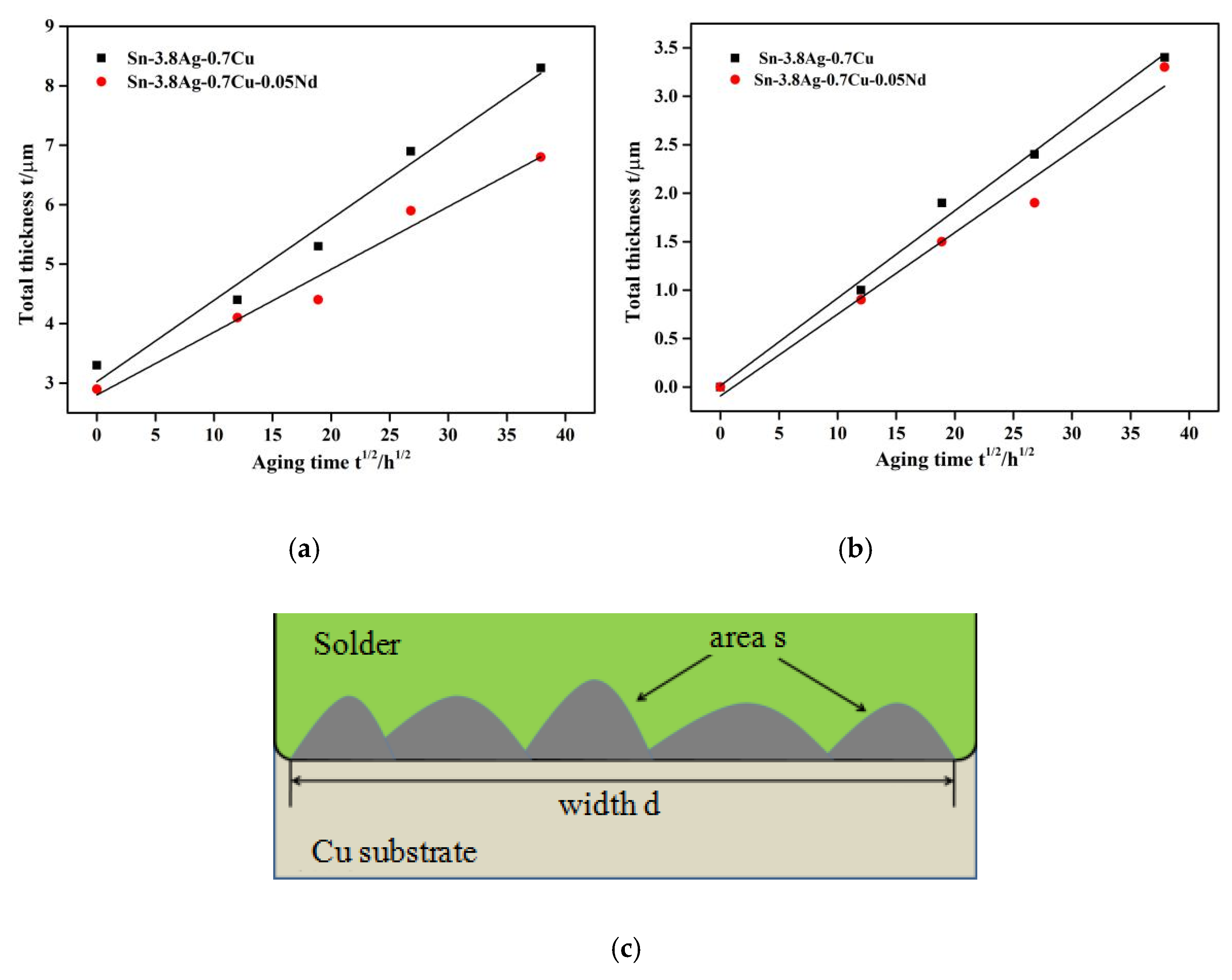
3.3. Thickness of Interfacial IMC Layer

The thicknesses of both Cu6Sn5 and Cu3Sn IMC layers increased with aging time in SAC387/Cu and SAC0387-0.05Nd/Cu interface. Figure 7c shows the computing process of IMC layer’s thickness. The average thickness of IMC layer t was calculated by t = s/d, where s represents the area of IMC layer, which was analyzed by Image Pro-plus software, and d was measured as the width of the interface. Table 1 summarized the thickness of IMC layers after 1440 h aging; it can be seen that the thickness of total interfacial IMC layer at SAC387/Cu interface increased to 8.3 μm, while that at the SAC0387-0.05Nd/Cu was 6.8 μm. Moreover, the interfacial Cu3Sn IMC layer reached 3.4 and 3.3 μm, respectively. As a result, trace amount of Nd could effectively inhibit the growth of interfacial IMCs.
Generally, the growth of interfacial IMC layer is controlled by atom diffusion. The relationship between the thickness of interfacial IMC layer and aging time coincides with the following diffusion formula [13]:
T t = T 0 + D t
where Tt is the thickness of interfacial IML after a certain time t, T0 is the initial thickness, D is the growth coefficient, as can be obtained from the slope of linear fitted curve of interfacial IMC layer thickness with aging time, as shown in Figure 7. Here below are the fitted equations:
T ( S A C 387 T o t a l ) = 3.024 + 0.137 t ;   T ( S A C 387 C u 3 S n ) = 0.023 + 0.090 t
T ( S A C 387 0.05 N d T o t a l ) = 2.801 + 0.105 t ;   T ( S A C 387 - 0.05 N d C u 3 S n ) = 0.103 + 0.084 t
It was calculated that the growth constant of total interfacial IMCs (DT) and Cu3Sn (DCu3) in the SAC387/Cu joint was 1.88 × 10⁻¹⁰ cm2/s and 0.81 × 10⁻¹⁰ cm2/s, respectively, while in SAC0387-0.05Nd/Cu joint the growth constant was 1.10 × 10⁻¹⁰ cm2/s and 0.71 × 10⁻¹⁰ cm2/s, respectively. Obviously, doping with 0.05 wt. % Nd can distinctly decrease the growth constant of total IMCs growth, while slightly decrease the growth constant of Cu3Sn (DCu3). The decrease in growth constant of total IMCs was mainly caused by the pinning effect on the growth of Cu6Sn5 exerted by Nd atoms. From the standpoint of thermodynamics, the growth driving force of Cu6Sn5 IMC layer depends on the activity of its reactants, that is, the Gibbs free energy of its formation can be expressed as follows:
Δ G ( C u 6 S n 5 ) = R T [ ln α S n C u C u 6 S n 5 ln α S n C u 6 S n 5 s o l d e r ]
where ΔG is the Gibbs free energy, R is the gas constant, T is the absolute temperature and α is the activity of Sn. The element Nd has the priority to combine with Sn to form compound, which could reduce the activity of Sn near the interface, which caused positive influence on the interface morphology of SAC387/Cu solder joint.

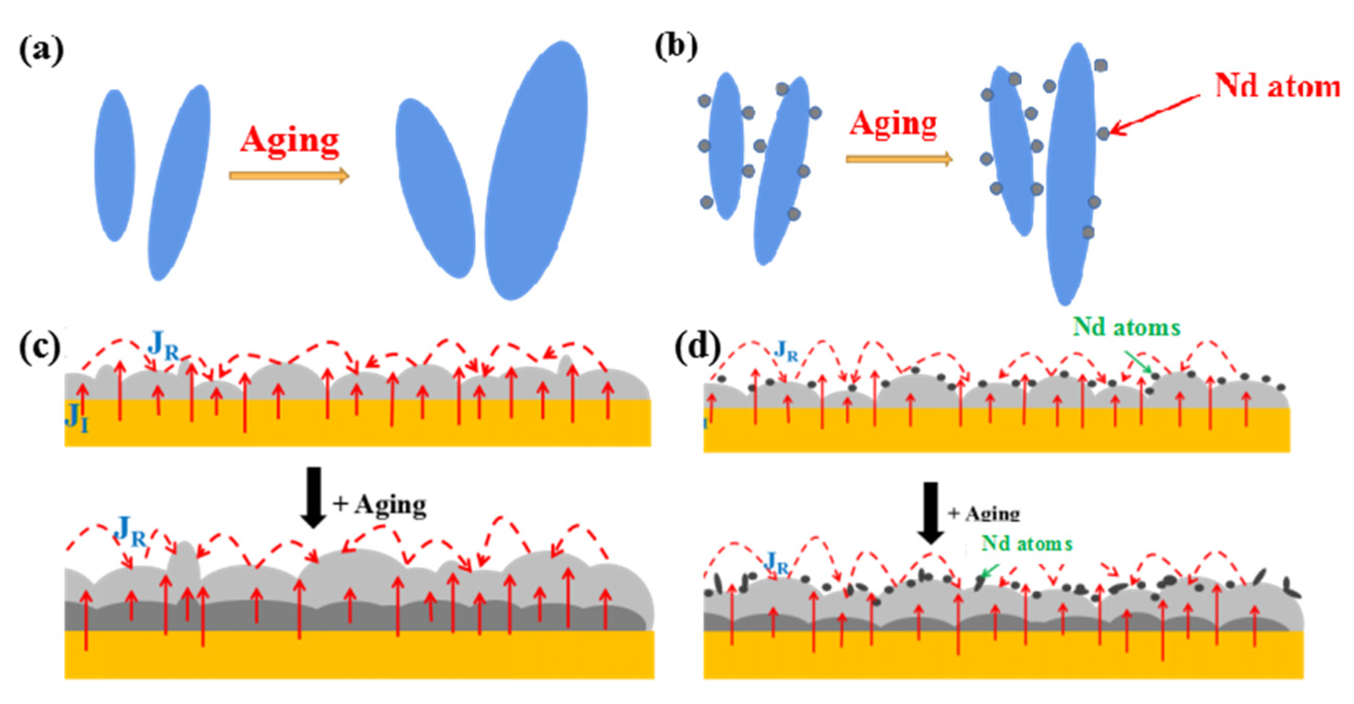
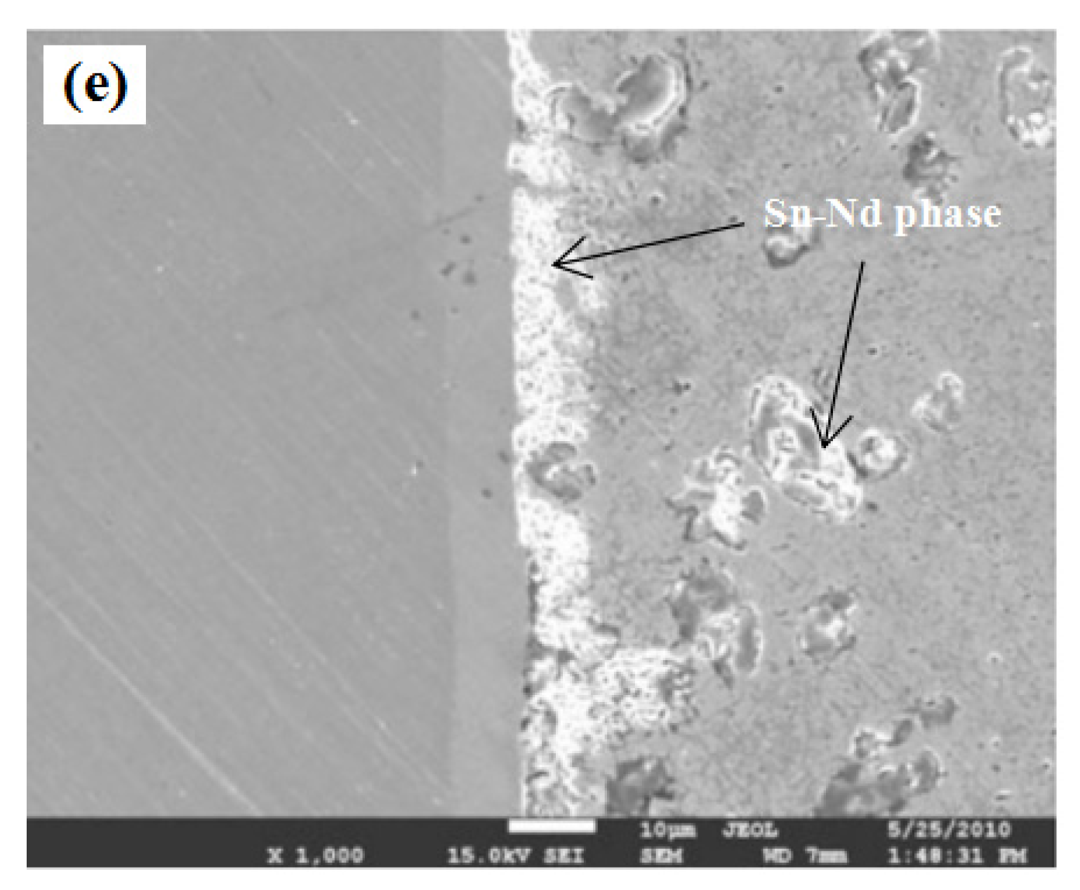
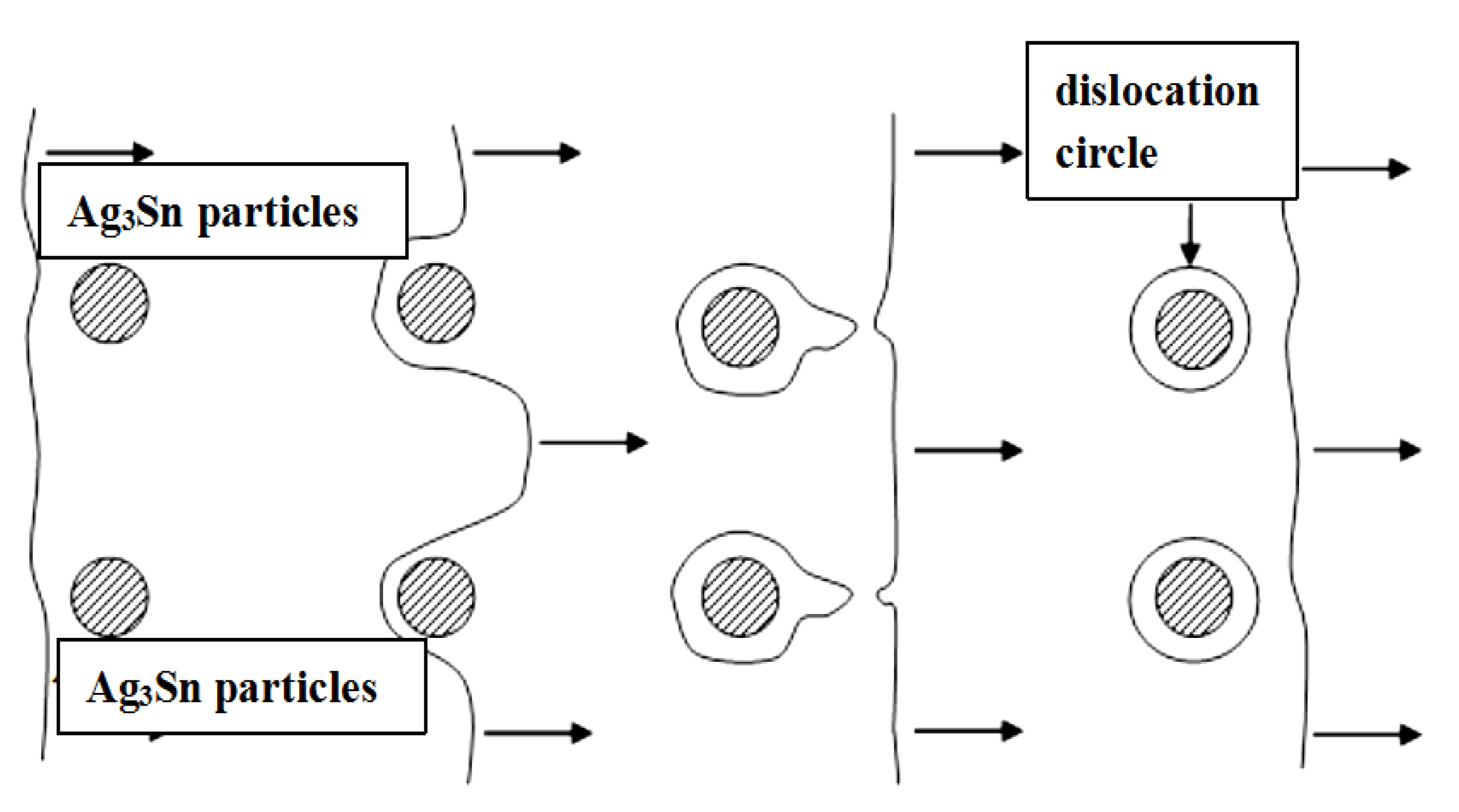
3.4. The Role of Ag3Sn on High-Temperature Reliability Enhancement

It should be noted that the significant change of Ag3Sn IMCs morphology also played an important role in enhancing the high-temperature reliability of solder joint. According to the particle strengthening proposed by Orwan: when the dislocations bypass the hard deformed particles, the repulsion force of the particles to dislocations is large enough, and the dislocation lines are blocked and bent. With the increase of applied loading, the dislocations are forced to move forward in a bending manner. The schematic diagram of dislocations bypassing the strengthened particles is shown in Figure 8.
The critical shear stress required to bypass the particles according to Orwan mechanism is called Orwan stress, as expressed by the formula below:
τ 0 = G b λ α f 0.5 r 1
where the constant for edge dislocation is 0.093 and for screw dislocation is 0.14, f is the volume fraction of particles, and r is the average radius of particles (μm). As can be obtained, the higher density of particles and smaller radius, the effect of strengthening mechanism could perform more obviously. In SAC387-0.05Nd/Cu solder, the size of Ag3Sn IMCs was refined obviously from micron scale to nano scale as can be seen in Figure 9 and Table 2. These nano-scaled Ag3Sn IMCs can serve as the particles above and hindering the motion of dislocations, delaying the decrease of shear force during high temperature aging. In addition, it can be obtained from Figure 9 that nano-scaled Ag3Sn IMCs adsorbed on the surface of interfacial Cu6Sn5 IMCs can hinder the diffusion of Sn, Cu atoms and finally hindering the growth of interfacial Cu6Sn5 IMCs.

4. Conclusions

In this study, the effect of appropriate Nd additions on high-temperature reliability of SAC387/Cu solder joint was investigated and the following conclusions were obtained.
The shear force of SAC387-0.05Nd/Cu solder joint was evidently improved compared with SAC387/Cu solder joint. In addition, SAC387-0.05Nd/Cu solder joint maintained excellent mechanical property even after 1440 h aging including higher shear force and better ductility compared with SAC387/Cu solder joint.
SAC387-0.05Nd solder obtained remarkable refined microstructure with smaller IMCs distributing on Sn matrix even after aging treatment. The growth of interfacial IMC layers (Cu6Sn5 + Cu3Sn) in solder joint was inhibited by Nd addition. Theoretical analysis indicated that 0.05 wt. % addition of Nd could distinctly decrease the growth constant of Cu6Sn5 IMCs and slightly decrease the growth constant of Cu3Sn IMCs, respectively.

Author Contributions

Conceptualization, P.X.; methodology, P.X. and J.T.; software, P.X.; validation, P.X., J.T. and P.H.; formal analysis, P.X.; investigation, P.X. and J.T.; resources, W.L. and S.Z.; data curation, P.X., W.L. and S.Z.; writing—original draft preparation, P.X.; writing—review and editing, P.X.; visualization, P.X.; supervision, P.H.; project administration, P.X.; funding acquisition, P.X. All authors have read and agreed to the published version of the manuscript.

Funding

This research was funded by National Natural Science Foundation of China (Grant No.51605226).

Conflicts of Interest

The authors declare no conflict of interest.

References

  1. Lee, C.-J.; Min, K.D.; Park, H.J.; Kim, J.-H.; Jung, S.-B. Effect of Sn-Decorated MWCNTs on the Mechanical Reliability of Sn–58Bi Solder. Electron. Mater. Lett. 2019, 15, 693–701. [Google Scholar] [CrossRef]
  2. Xue, P.; Liang, W.; He, P.; Suganuma, K.; Zhang, H. Tin Whisker Growth Inhibition in RE-Doped Sn-Zn Soldered Joints. Appl. Sci. 2019, 9, 1406. [Google Scholar] [CrossRef] [Green Version]
  3. Xiong, M.-Y.; Zhang, L.; He, P.; Long, W.-M. Stress analysis and structural optimization of 3-D IC package based on the Taguchi method. Solder. Surf. Mt. Technol. 2019, 32, 42–47. [Google Scholar] [CrossRef]
  4. Wu, J.; Xue, S.; Wang, J.-W.; Liu, S.; Han, Y.-L.; Wang, L.-J. Recent progress of Sn-Ag-Cu lead-free solders bearing alloy elements and nanoparticles in electronic packaging. J. Mater. Sci. Mater. Electron. 2016, 27, 12729–12763. [Google Scholar] [CrossRef]
  5. Wang, J.; Xue, S.; Zhang, P.; Zhai, P.; Tao, Y. The reliability of lead-free solder joint subjected to special environment: A review. J. Mater. Sci. Mater. Electron. 2019, 30, 9065–9086. [Google Scholar] [CrossRef]
  6. Jie, W.; Xue, S.; Jingwen, W.; Jianxin, W.; Deng, Y. Enhancement on the high-temperature joint reliability and corrosion resistance of Sn–0.3Ag–0.7Cu low-Ag solder contributed by Al2O3 Nanoparticles (0.12 wt%). J. Mater. Sci. Mater. Electron. 2018, 29, 19663–19677. [Google Scholar] [CrossRef]
  7. Huang, M.-L.; Zhao, N.; Liu, S.; He, Y.-Q. Drop failure modes of Sn–3.0Ag–0.5Cu solder joints in wafer level chip scale package. Trans. Nonferrous Met. Soc. China 2016, 26, 1663–1669. [Google Scholar] [CrossRef]
  8. Zhang, L.; Long, W.M.; Wang, F.J. Microstructures, interface reaction, and properties of Sn-Ag-Cu and Sn-Ag-Cu-0.5CuZnAl solders on Fe substrate. J. Mater. Mater. Electron. 2020, 31, 6645–6653. [Google Scholar] [CrossRef]
  9. Lau, C.S.; KhorM, C.Y.; Soares, D.; Teixeira, J.C.F.; Abdullah, M. Thermo-mechanical challenges of reflowed lead-free solder joints in surface mount components: A review. Solder. Surf. Mt. Technol. 2016, 28, 41–62. [Google Scholar] [CrossRef]
  10. Tang, Y.; Li, G.Y.; Chen, D.Q.; Pan, Y.C. Influence of TiO nanoparticles on IMC growth in Sn-3.0Ag-0.5Cu-xTiO solder joints during isothermal aging process. J. Mater. Sci. Mater. Electron. 2014, 25, 981–991. [Google Scholar] [CrossRef]
  11. Fouzder, T.; Shafiq, I.; Chan, Y.; Sharif, A.; Yung, W.K. Influence of SrTiO3 nano-particles on the microstructure and shear strength of Sn–Ag–Cu solder on Au/Ni metallized Cu pads. J. Alloy. Compd. 2011, 509, 1885–1892. [Google Scholar] [CrossRef]
  12. Min, D.; Xing, W.; Yu, X.; Ma, L.; Zuo, W.; Ji, Z. Effect of micro alumina particles additions on the interfacial behavior and mechanical properties of Sn-9Zn-1Al2O3 nanoparticles on low temperature wetting and soldering of 6061 aluminum alloys. J. Alloy. Compd. 2018, 739, 481–488. [Google Scholar] [CrossRef]
  13. Wu, J.; Xue, S.; Wang, J.; Huang, G. Effect of 0.05 wt. % Pr Addition on Microstructure and Shear Strength of Sn-0.3Ag-0.7Cu/Cu Solder Joint during the Thermal Aging Process. Appl. Sci. 2019, 9, 3590. [Google Scholar] [CrossRef] [Green Version]
  14. Zhang, L.; Xue, S.; Gao, L.-L.; Chen, Y.; Yu, S.-L.; Sheng, Z.; Zeng, G. Effects of trace amount addition of rare earth on properties and microstructure of Sn–Ag–Cu alloys. J. Mater. Sci. Mater. Electron. 2009, 20, 1193–1199. [Google Scholar] [CrossRef]
  15. Sadiq, M.; Pesci, R.; Cherkaoui, M. Impact of Thermal Aging on the Microstructure Evolution and Mechanical Properties of Lanthanum-Doped Tin-Silver-Copper Lead-Free Solders. J. Electron. Mater. 2013, 42, 492–501. [Google Scholar] [CrossRef] [Green Version]
  16. Gao, L.; Xue, S.; Zhang, L.; Sheng, Z.; Zeng, G.; Ji, F. Effects of trace rare earth Nd addition on microstructure and properties of SnAgCu solder. J. Mater. Sci. Mater. Electron. 2009, 21, 643–648. [Google Scholar] [CrossRef]
  17. Ye, H.; Xue, S.; Pecht, M.G. Effects of thermal cycling on rare earth (Pr)-induced Sn whisker/hillock growth. Mater. Lett. 2013, 98, 78–81. [Google Scholar] [CrossRef]
  18. Mansour, M.M.; Saad, G.; Wahab, L.; Fawzy, A. Indentation creep behavior of thermally aged Sn-5wt%Sb-1.5wt%Ag solder integrated with ZnO nanoparticles. J. Mater. Sci. Mater. Electron. 2019, 30, 8348–8357. [Google Scholar] [CrossRef]
  19. Jasli, N.A.; Hamid, H.A.; Mayappan, R. Morphology and Intermetallics Study of (Sn-8Zn-3Bi)-1Ag Solder under Liquid-State Aging. Adv. Mater. Res. 2012, 620, 273–277. [Google Scholar] [CrossRef]
  20. Hu, Y.-H.; Xue, S.; Wang, H.; Ye, H.; Xiao, Z.; Gao, L.-L. Effects of rare earth element Nd on the solderability and microstructure of Sn–Zn lead-free solder. J. Mater. Sci. Mater. Electron. 2010, 22, 481–487. [Google Scholar] [CrossRef]
Figure 1. Illustration of shear loading.
Applsci 10 08935 g001
Figure 2. Shear force of solder joint with fracture morphology after certain aging time. (a): 0 h, SAC387/Cu; (b): 720 h, SAC387/Cu; (c): 1440 h, SAC387/Cu; (d): 0 h, SAC387-0.05Nd/Cu; (e): 720 h, SAC387-0.05Nd/Cu; (f): 1440 h, SAC387-0.05Nd/Cu.
Applsci 10 08935 g002
Figure 3. Microstructures of as-soldered and -aged solder matrix and its solder joints: (a,b) as-soldered SAC387 and SAC387-0.05Nd solder matrix; (e,f) as-soldered SAC387/Cu and SAC387-0.05Nd/Cu solder joint; (c,d) as-aged (1440 h) SAC387 and SAC387-0.05Nd solder matrix; (g,h) as-aged (1440 h) SAC387 and SAC387-0.05Nd solder matrix.
Applsci 10 08935 g003
Figure 4. Microstructure evolution of SAC387 solder/Cu solder joint after aging treatment: (a) 140 h; (b) 360 h; (c) 720 h; (d) 1440 h.
Applsci 10 08935 g004
Figure 5. Microstructure evolution of SAC387-0.05Nd solder/Cu solder joint after aging treatment: (a) 140 h; (b) 360 h; (c) 720 h; (d) 1440 h.
Applsci 10 08935 g005
Figure 6. Mechanism of Nd atoms on hindering the growth of intermetallic compounds (IMCs): (a,b) IMcs in solder matrix; (c,d) interfacial IMCs; (e) effect of Nd in Sn-Zn-Nd solder [19]. (JI and JR stands for the interfacial reaction flux and the ripening flux of Cu atoms, respectively).
Applsci 10 08935 g006aApplsci 10 08935 g006b
Figure 7. Thickness of the interfacial IMC layers (IMLs) aged at 150 °C. (a): Thickness of Cu6Sn5 + Cu3Sn layer; (b): Thickness of Cu3Sn layer; (c): The computing process of IMC layer’s thickness.
Applsci 10 08935 g007
Figure 8. Schematic diagram of dislocation bypassing Ag3Sn IMC particles.
Applsci 10 08935 g008
Figure 9. The morphology of Ag3Sn IMCs on the surface of interfacial Cu6Sn5 IMCs.
Applsci 10 08935 g009
Table 1. Thickness of IMC layers in the interface of solder/Cu during the aging process.
Thickness (μm)Aging Time (h)
IMC Layer01443607201440
Cu6Sn5 + Cu3Sn in SAC3873.34.45.36.98.3
Cu3Sn in SAC38701.01.92.43.4
Cu6Sn5 + Cu3Sn in SAC387-0.05Nd2.94.14.45.96.8
Cu3Sn in SAC387-0.05Nd00.91.51.93.3
Table 2. EDS results of spot A and spot B.
ElementSpot ASpot B
Wt(%)At.(%)Wt(%)At.(%)
Cu33.6848.68--
Sn66.3251.3228.7226.34
Ag--71.2873.66
Publisher’s Note: MDPI stays neutral with regard to jurisdictional claims in published maps and institutional affiliations.

