Article

Time-Synchronization Method for CAN–Ethernet Networks with Gateways

1
School of Mechanical Engineering, Pusan National University, Pusan 46241, Korea
2
Division of Automotive Engineering, Dong-eui Institute of Technology, Pusan 47230, Korea
*
Author to whom correspondence should be addressed.
Appl. Sci. 2020, 10(24), 8873; https://doi.org/10.3390/app10248873
Submission received: 12 November 2020 / Revised: 3 December 2020 / Accepted: 9 December 2020 / Published: 11 December 2020

Abstract

:

Featured Application

Authors are encouraged to provide a concise description of the specific application or a potential application of the work. This section is not mandatory.

Abstract

Time-synchronization technology can provide a common notion of time among the participating nodes on a network. This is essential not only for protocol operation for time-critical services but also for the time stamp for information included in the message. Precise time information can be very crucial for such things as autonomous driving because there are various sensor measurements from multiple cameras, and radio detection and ranging (radar) and light detection and ranging (LiDAR) are used for perceiving the current situation via sensor fusion. A well-known synchronization method, IEEE 1588, denoted as the precision time protocol (PTP), can be used for various applications. For in-vehicle networks of autonomous cars, we have to consider that the network may be comprised of subnetworks based on different protocols such as controller area network (CAN) and Ethernet. However, implementing PTPs on such heterogeneous vehicle networks causes several problems. First, the PTP procedure must be modified to be implement on a CAN network. Second, to calculate the delay and offset for PTP, the processing delay that occurs during message conversion must be considered. In this paper, we propose a synchronization method for CAN–Ethernet networks to solve these problems. The performance of the proposed synchronization method is evaluated by experiments on a real CAN–Ethernet network.

1. Introduction

As autonomous driving technology has rapidly developed and become closer to commercialization, ensuring that stability and reliability of vehicle control and communication technologies are getting more important [1,2]. In particular, the quantity of data exchanged in a vehicle has increased exponentially owing to sensors, such as cameras, LiDAR, and radar, for recognizing other vehicles and road conditions and controlling the vehicle, in addition to external communication via V2X technology [3,4]. This increase in the amount of data inside of a vehicle has led to limitations in existing in-vehicle network (IVN) protocols such as controller area network (CAN), local interconnect network (LIN), and FlexRay. Thus, a new communication protocol that ensures high bandwidth is required as a solution.
Ethernet is one such communication technology that provides a high bandwidth [5]. However, Ethernet tends to cost more because it requires connection equipment, such as switches, and uses a 1:1 connection. It also introduces problems such as providing a higher performance than necessary for certain devices. Furthermore, many sensors simply do not have an option to connect to an Ethernet. Accordingly, a more realistic alternative, at present, is to use both a conventional vehicle network such as CAN and a high-bandwidth network such as Ethernet, for which a gateway connects the different networks [6].
The performance of an autonomous vehicle, which integrates and processes the data measured from various sensors, may vary depending on whether there is time information of the sensor measurement [7,8,9,10]. This is because the controller may have temporal distortion, that is, it is trying to perceive its situation by patching up numerous pieces of information that may be captured at different instants. In contrast, sensor measurements with time information allow the autonomous driving controller to be aware of time differences among the measurements and to compensate for the time differences for better perception of the situation. Therefore, to improve autonomous vehicle performance, increasing research is being conducted concerning time synchronization among the sensors and controllers connected via communication networks.
For widely-used CAN networks, ECUs (electronic controller units) can be synchronized by using AutoSAR 4.2.2, which is a well-known middleware for ECUs [11,12]. Time synchronization with AutoSAR has a master and slave structure; the slave calculates the delay and offset and corrects its own clock via two messages transmitted from the master. Within this process, time can be synchronized, such that the clock error between the master and slave is within a maximum of 10 µs [11,12]. However, AutoSAR requires quite significant computing resources, which makes it difficult to be implemented on every CAN node. In a FlexRay network, the time synchronization is based on the fact that the send and receive time points of all static messages are known to each FlexRay node. All FlexRay nodes compare the a priori known time points with the time points of synchronization messages actually received. Then FlexRay nodes create a sorted list of differences, from which they compute their offset correction value using the fault tolerant midpoint (FTM) algorithm [13]. Time-triggered Ethernet (TT-Ethernet) adopts a distributed time-synchronization algorithm and maintains global time by exchanging protocol control frames (PCFs) among synchronization components [14]. Synchronization components include a synchronization master (SM), a synchronization client (SC), and a compression master (CM). The synchronization process is as follows: first, the SM sends PCFs to the CM, and the CM calculates the average of PCF reception times and sends them to SMs and SCs by loading them into the new PCF. The new PCF is then used to calibrate nodes clocks [
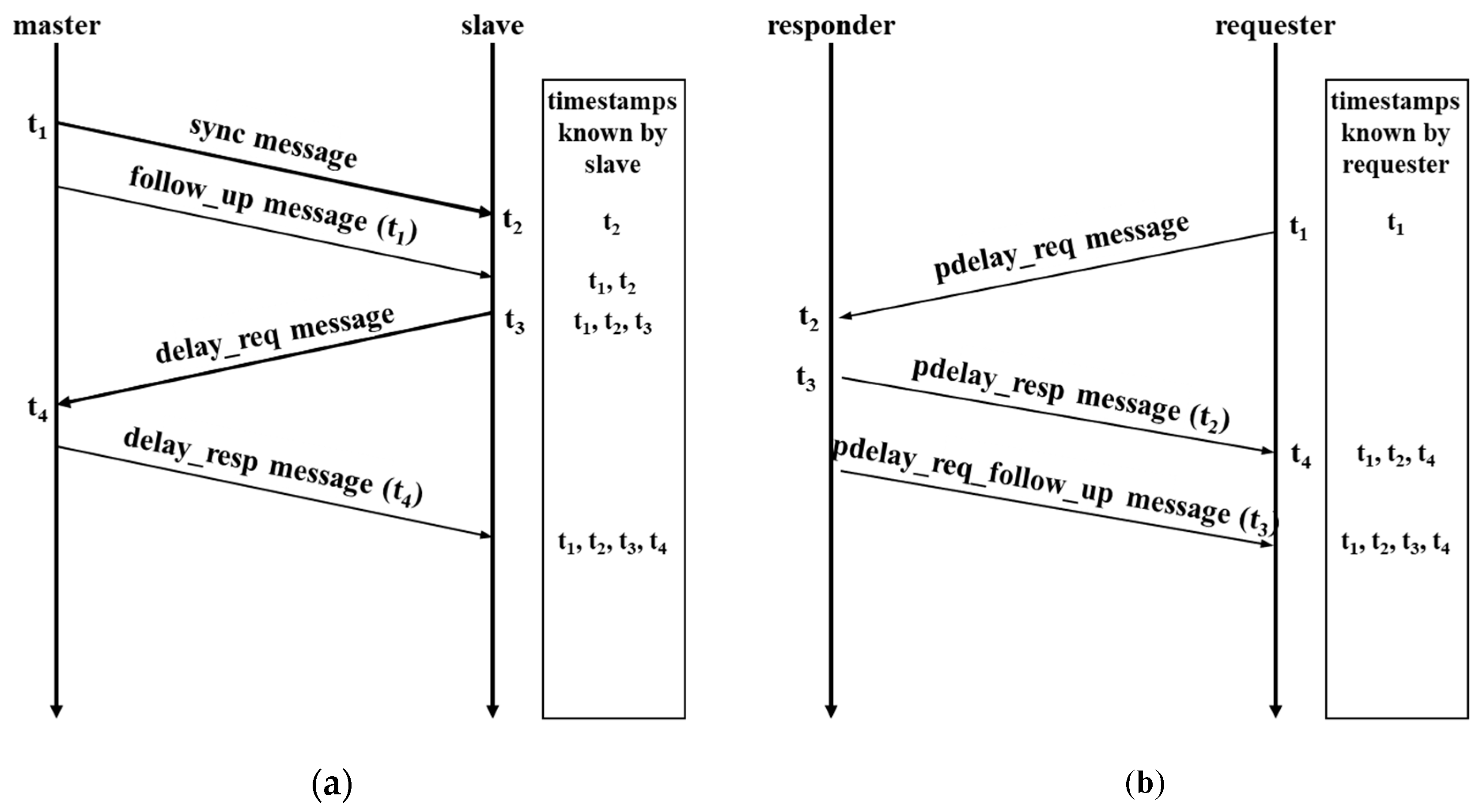
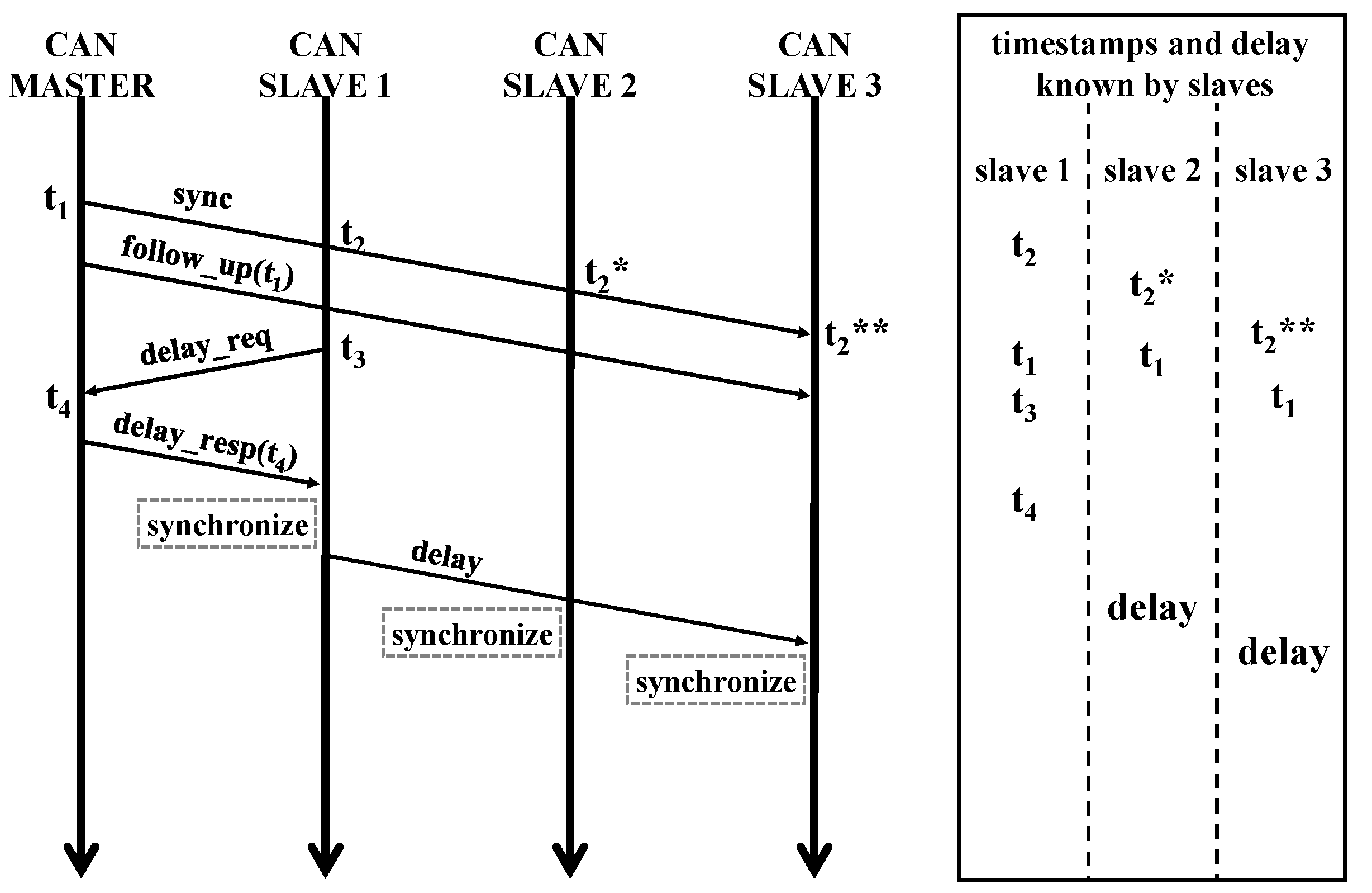
15]. However, it is difficult to expect extremely-precise time synchronization for all nodes because FlexRay and TT-Ethernet use average values to compensate for delays for time synchronization. In contrast, time synchronization in an Ethernet network can be accomplished by using the precision time protocol (PTP), which is specified by IEEE 1588 standard [16]. In the PTP, the time is synchronized by exchanging four messages between the master and slave nodes. The time-synchronization error can be controlled to units of nanoseconds depending on the type of timestamp, thereby permitting highly-precise time synchronization [16,17].
Hence, while the time-synchronization method for a single-protocol network, either CAN or Ethernet network is established, heterogeneous communication environments, such as a CAN–Ethernet network, require additional work to achieve time synchronization. In particular, a CAN needs some type of synchronization unless each node runs AutoSAR while FlexRay and media oriented systems transport (MOST) have their own synchronization mechanisms built as a part of their protocols. For a CAN network, Park applied the time-synchronization mechanism of IEEE 1588 [18]. Next, Lee presented a method for improving the quality of service (QoS) of the network in a vehicle that applies the time trigger technique of FlexRay and Ethernet [19]; in the study, external clocks of the Ethernet nodes and gateway were first synchronized through the PTP. Then, by setting the external clock of the gateway synchronized through the PTP as the global clock, the devices in the FlexRay area were synchronized using the time-synchronization protocol supported by FlexRay. However, the study conducted by Lee used two synchronization protocols, and it was limited because a gateway with an external clock was necessary. Therefore, we focused on the time synchronization of CAN–Ethernet network because CAN is almost a de facto standard with no synchronization procedure except using AutoSAR. Furthermore, Ethernet with TSN functionalities can provide high bandwidth, time synchronization, and real-time capability.
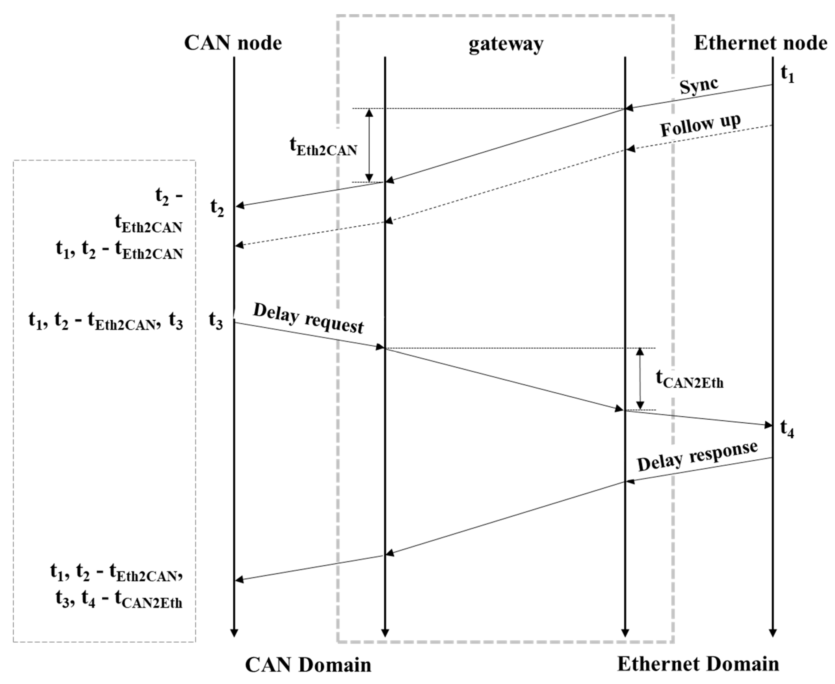
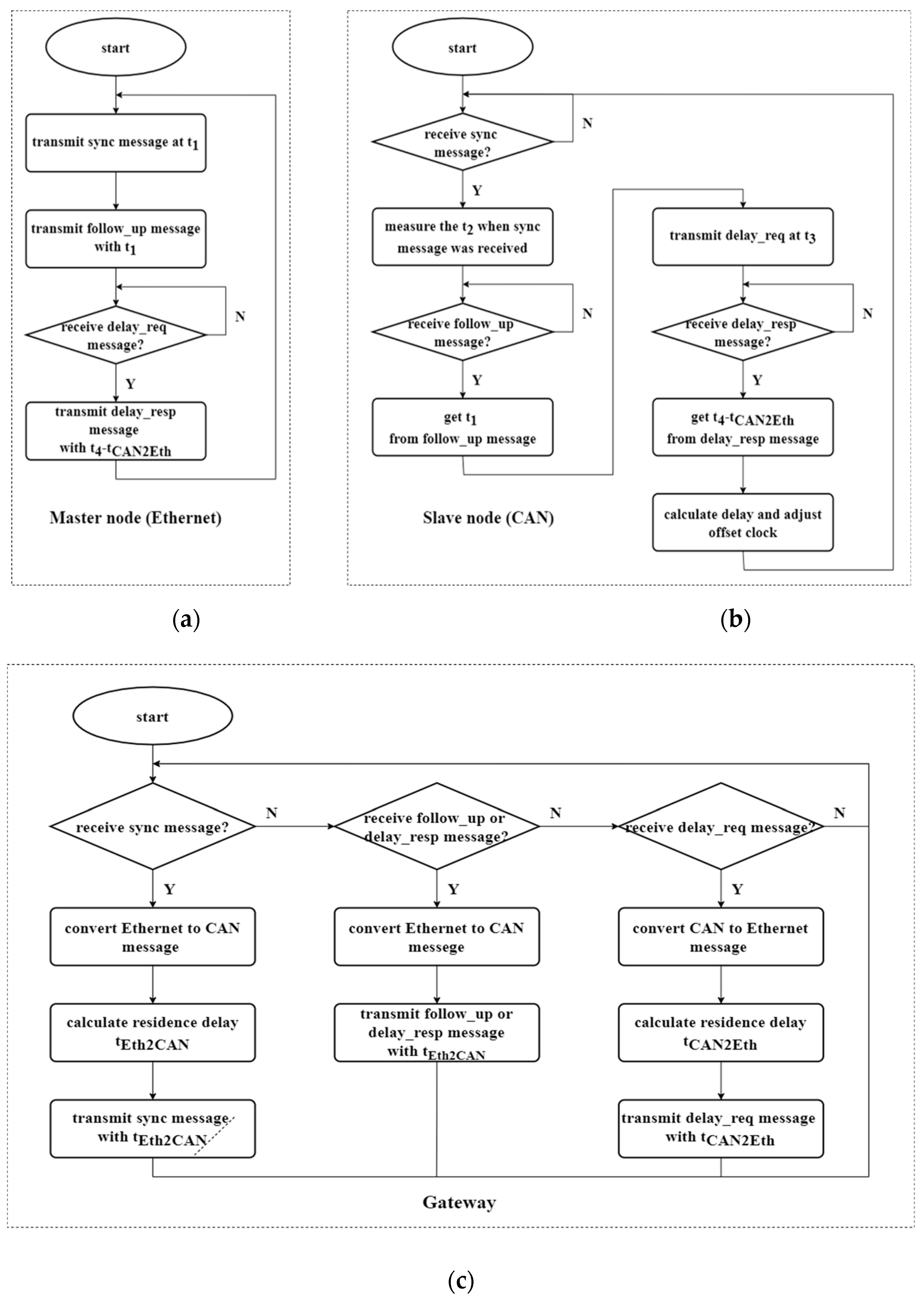
This study proposes a time-synchronization method for CAN–Ethernet-heterogeneous communication networks. A method for applying the PTP mechanism to CAN communication to achieve precise time synchronization and a method for correcting the processing delay_required by the gateway is proposed. Furthermore, a laboratory-scale network environment was configured to assess the synchronization performance, and the applicability of the proposed time-synchronization method was confirmed.
This paper consists of five sections. Section 2 describes the IEEE 1588-based time-synchronization method for Ethernet networks, and Section 3 describes the proposed time-synchronization method for CAN–Ethernet networks. Section 4 presents the performance evaluation environment and results of the proposed time-synchronization method, and Section 5 lists conclusions of the study and describes the direction of future research.

2. IEEE 1588 (PTP)

2.1. Overview of IEEE 1588

IEEE 1588, also referred to as the PTP, is an international standard for the precise time clock synchronization of measurement and control systems used in various environments, such as communications, local computing, and distributed systems. IEEE 1588v1 (first published in 2002) operated only on local area networks (LANs), while IEEE 1588v2 (published in 2008) supports unicast and multicast modes. Through these standards, packets containing time-synchronization information are transmitted through routers and switches, providing precise time synchronization for various Ethernet-based protocols. IEEE 1588 specifies several functions for time synchronization; these include the best master clock (BMC) algorithm, which selects a clock master in a master–slave structure, and a method that calculates the delay and offset to synchronize the time clock of the slave nodes with that of the master. The standard also specifies several measures in the case of failure of the device selected as the master.

2.2. Time-Synchronization Mechanism of PTP

PTP, which is defined in IEEE 1588, calculates the delay and offset through PTP messages exchanged between the master and slave and synchronizes their clocks. In this process, the PTP message type is determined according to the synchronization mechanism. Mechanisms for correcting the offset and delay through PTP include end-to-end (E2E) and peer-to-peer (P2P), which are also referred to as a delay-request response and peer delay, respectively.

2.2.1. End-To-End Mechanism

Figure 1a presents the synchronization mechanism of the E2E method. In the E2E method, four types of synchronization messages are exchanged between the master and slave, through which the delay and offset are calculated and time is synchronized. First, the master transmits a synchronization message to the slave at time t1, and the slave receives it at time t2. Next, the master node stores t1 in a follow-up message and transmits it to the slave node. The slave then transmits a delay-request message at time t3, and the master receives it at time t4. Finally, the master stores t4 in the delay-response message and transmits it to the slave. Through this process, the slave can acquire four timestamps (t1, t2, t3, and t4) to calculate the offset and propagation delay. Equations (1) and (2) are used to calculate the delay and offset between the master and slave nodes. In this process, the network must provide a link with a symmetrical structure, in which the transmission rates of the master and slave in both directions are identical.
d e l a y = [ ( t 4 t 1 ) ( t 3 t 2 ) ] 2
o f f s e t = t 2 t 1 d e l a y = [ ( t 2 t 1 ) ( t 4 t 3 ) ] 2
The four timestamps used in Equation (1) are the timestamp values generated by the master and slave nodes; the timestamp can be classified as a software- or hardware-based timestamp depending on the measurement method. The accuracy of the timestamp is highest when generated close to the physical layer, and, depending on whether the device supports PTP, the hardware-based timestamp is measured in the media access control (MAC) or physical (PHY) layer.

2.2.2. Peer-To-Peer Mechanism

In the E2E mechanism, the synchronization accuracy may decline if the paths connecting the master and slaves are composed of numerous devices. However, the P2P mechanism addresses this by performing synchronization between all neighboring devices, such as switches or routers. Although this technique requires that all neighboring devices support the P2P mechanism, it can ensure more accurate time synchronization. Moreover, unlike the E2E mechanism, the delay and offset can be calculated through three messages in the P2P mechanism. Figure 1b demonstrates the synchronization mechanism of the P2P method. First, the requester node transmits a pdelay-request message at time t1, and the responder node receives it at time t2. Next, the responder node stores time t2 in the pdelay-response message and transmits it to the requester node, and the requester receives it at time t4. Finally, the responder stores time t3 in a pdelay-request follow-up message and transmits it to the requester. Through this process, the requester acquires four timestamps and calculates the propagation delay and offset using Equations (1) and (2). The P2P mechanism is also based on a link with a symmetrical structure in which the transmission rates in both directions are identical, and the time-synchronization accuracy is determined according to the measurement position of the timestamp.

3. Time-Synchronization Algorithm of Heterogeneous Networks

3.1. Network-Synchronization Procedure via a Gateway

A gateway is needed to convey messages from one type of network to another. It is unavoidable to have a processing delay to convert the messages, which impacts the time-synchronization performance. Figure 2 illustrates the time-synchronization process of the E2E method in a CAN–Ethernet network including a gateway with an Ethernet node as a master. tEth2CAN indicates the processing delay_required to convert an Ethernet message into a CAN message, and tCAN2Eth denotes the processing delay_required to convert a CAN message into an Ethernet message. tEth2CAN is calculated by measuring the time interval from the time instant the gateway receives the Ethernet message to the moment it starts to transmit the converted CAN message. Conversely, tCAN2Eth is obtained by measuring the time interval from the time instant the gateway receives the CAN message to the time it begins to send the converted Ethernet message. Both tCAN2Eth and tEth2CAN may have different values because the time required for each network to receive and convert the message differs. Consequently, the network has an asymmetrical structure when a gateway is included, which can prevent precise synchronization. Equations (3) and (4) represent propagation delay and offset calculations, considering the processing delay that occurs when a gateway converts a message in a CAN–Ethernet network.
d e l a y = [ ( t 4 t 1 t E t h 2 C A N t C A N 2 E t h ) ( t 3 t 2 ) ] 2
o f f s e t = t 2 t 1 t E t h 2 C A N d e l a y = [ ( t 2 t 1 t E t h 2 C A N ) ( t 4 t 3 t C A N 2 E t h ) ] 2
To calculate the propagation delay and offset in a CAN–Ethernet network with a gateway, the slave must confirm the values of tEth2CAN and tCAN2Eth. For this purpose, the gateway can store the calculated value of tEth2CAN in the synchronization message and transmit it to the slave, while tCAN2Eth can be stored in the delay-request message and transmitted to the master. The master learns tCAN2Eth at time t4 after receiving the delay-request message, stores the value obtained by subtracting tCAN2Eth from t4 in the delay-response message, and transmits it to the slave.

3.2. Setting of the PTP Message Format

To synchronize the time between the Ethernet and CAN networks, the PTP messages must be converted into a format suitable for the message format of each network through the gateway. Figure 3 shows a comparison of the formats of the existing PTP and CAN messages and a converted PTP message format for time synchronization between heterogeneous networks. The PTP message consists of a header and timestamp, and the timestamp consists of a 6-byte-seconds field and 4-byte-nanoseconds field. In contrast, because the total size of the data field of a CAN message is 8 bytes, it is insufficient to store the timestamp of the PTP message. In this study, the upper two bytes of the seconds field in the existing PTP message are removed to store the 8-byte timestamp in the CAN message. These two deleted bytes are information used to mark the accurate year; hence, their exclusion from the timestamp should not significantly impact the system. If the accurate time is required, the master can transmit the 2-byte value deleted during system initialization to the slave and set the complete time.

3.3. Time- Synchronization Algorithm of the CAN–Ethernet Network

Figure 4 presents the time-synchronization algorithm of the master (Ethernet) and slave (CAN) nodes in the CAN–Ethernet network. In Figure 4a, the master transmits the synchronization message to the slave and stores the timestamp (t1) in the memory buffer. Then, after storing t1 in the follow-up message, it is transmitted to the slave. Next, it checks whether the delay-request message transmitted from the slave node has been received. If the delay-request message has been received, then the timestamp (t4) and timestamp included in the message (tCAN2Eth) are stored in the memory buffer. Finally, the calculated value of t4-tCAN2Eth is stored in the delay-response message and transmitted to the slave.
In Figure 4b, the slave checks whether the synchronization message transmitted from the master has been received. If the message has been received, then the timestamp (t2) and timestamp included in the synchronization message (tEth2CAN) are stored in the memory buffer. Next, it waits until the follow-up message transmitted from the master is received. If the follow_up message is received, then the timestamp (t1) included in the message is stored in the memory buffer. A delay-required message is then transmitted to the master, and after storing the timestamp (t3), it waits until the delay-response message transmitted from the master is received. If the delay-response message is received, then the timestamp (t4-tCAN2Eth) included in the message is stored. Finally, the saved timestamps (t1, t2, t3, t4-tCAN2Eth, and tEth2CAN) are used to calculate the delay and offset.
Figure 4c shows the time-synchronization algorithm of the gateway in the CAN–Ethernet network. The gateway first checks whether a synchronization message transmitted from the master is received. If a synchronization message is received, then it is converted into a CAN message, and tEth2CAN, which is the time from the receipt of the synchronization message until the completion of conversion, is calculated. tEth2CAN is then stored in the synchronization message converted for the CAN network and transmitted to the slave. If a follow-up message or delay-response message transmitted from the master is received, it is converted into a CAN message and transmitted to the slave. Finally, once the delay-request message transmitted from the slave is received, it is converted into an Ethernet message, and tCAN2Eth, which is the time from the receipt of the delay-request message until the completion of conversion, is calculated. tCAN2Eth is then stored in the converted delay-request message and transmitted to the master.

3.4. Time-Synchronization Method of the CAN Network

The PTP procedure can be directly applicable to an homogeneous CAN network. Unlike Ethernet, which uses a 1:1 connection, a CAN network employs bus topology where broadcast transmission is readily available [20]. This feature can be used to synchronize all the CAN nodes without repeating PTP procedure for each node. We can design the procedure so that a master node can transmit synchronization and follow-up messages only once. However, slave nodes will try to transmit a delay-request message almost simultaneously, which will cause message collisions. To prevent these collisions, we may assign different IDs for each delay-request message, which will increase the duration of the synchronization process and the network traffic. Instead, we selected a single slave node to perform the delay calculation using Equation (1) and let the node broadcast the results to other nodes. Figure 5 shows the method for sharing the delay between slave nodes. First, the master transmits synchronization and follow-up messages to all slaves, and slave 1 stores t1 and t2. Slaves 2 and 3 share t1, but because the reception time differs, they store t2* and t2**, respectively. Next, the time synchronization procedure is performed for only slave 1 to calculate the delay. The calculated delay is transmitted to the remaining slaves, and the previously-stored timestamps (t1 and t2*, or t1 and t2**) are used to calculate the offset using Equation (2). This modified procedure can simplify the synchronization over the broadcast medium although synchronization error may increase as the length of network increases.

4. Evaluation of the CAN–Ethernet Network Time-Synchronization Performance

Figure 6 shows the experimental setup for the performance evaluation of the CAN–Ethernet network synchronization. Five NXP MPC5748-LCEVB modules were used for the nodes and gateway. MPC5748 is a chipset for vehicle use and supports CAN (CAN FD) and 100-Mbps Ethernet networks. The network topology for the performance evaluation comprised a master node (Ethernet), gateway, and three slave nodes (CAN), and an oscilloscope was used to measure the synchronization error. To emulate a CAN network with many nodes, CAN slave 3 was connected with a 15 m cable. To generate timestamps, each node used a software-based timestamp.
The synchronization error is defined as the difference in the perceived global times. To measure the error, slave nodes were programmed to output trigger signals to a certain pin so that the oscilloscope captured the time instants. In addition, the synchronization procedure was periodically repeated every 1 s to limit the effect of difference in clock rates. The trigger signal for measuring synchronization performance was set to output approximately 800 ms after the time synchronization ended.
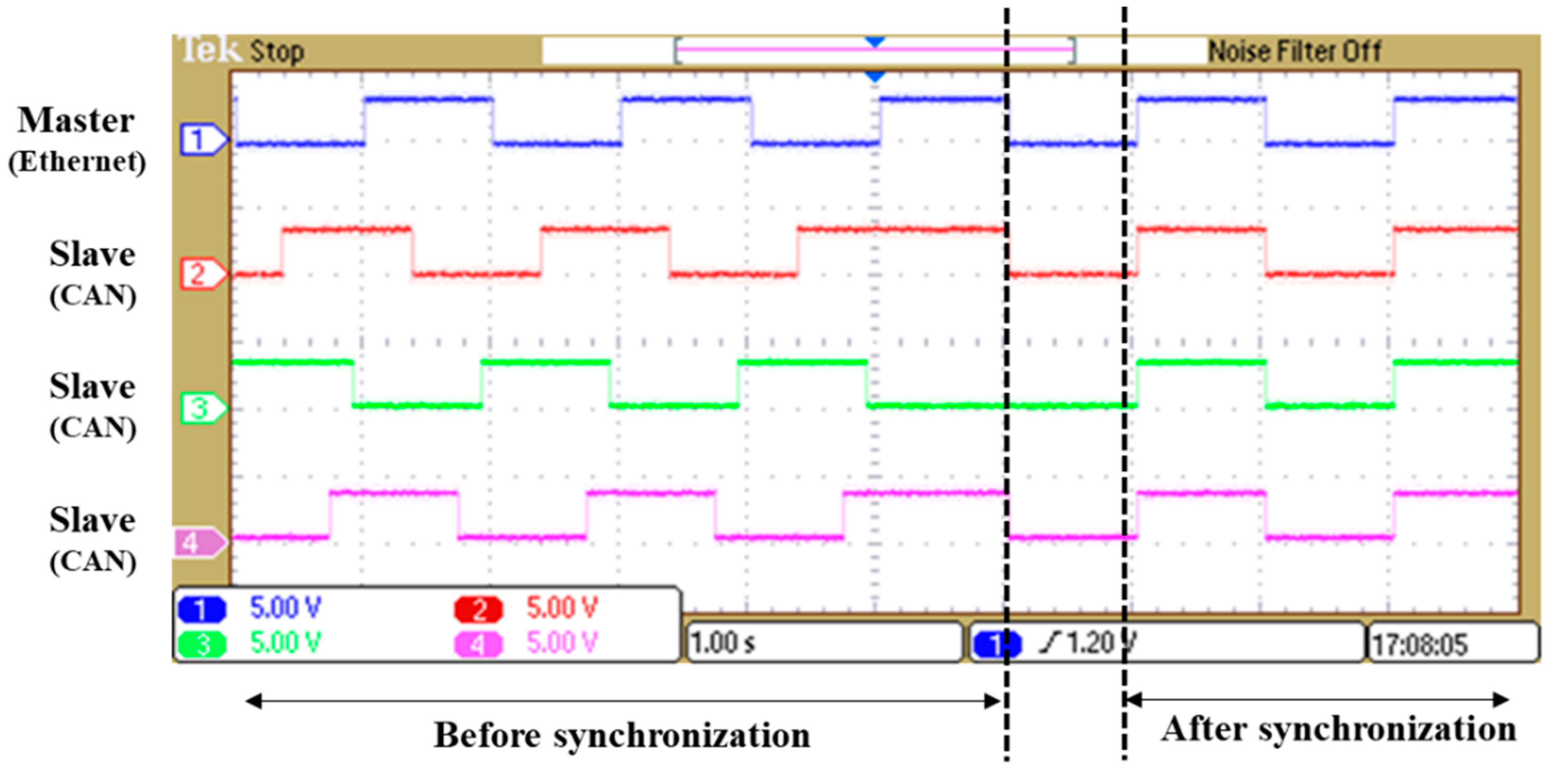
Figure 7 demonstrates the time difference of the trigger signals from the nodes before and after time synchronization was performed. The rising edges of the output signals from the nodes were not aligned before synchronization while the edges were rising almost simultaneously after synchronization. These results confirmed that the proposed algorithm enables time synchronization in the CAN–Ethernet network.
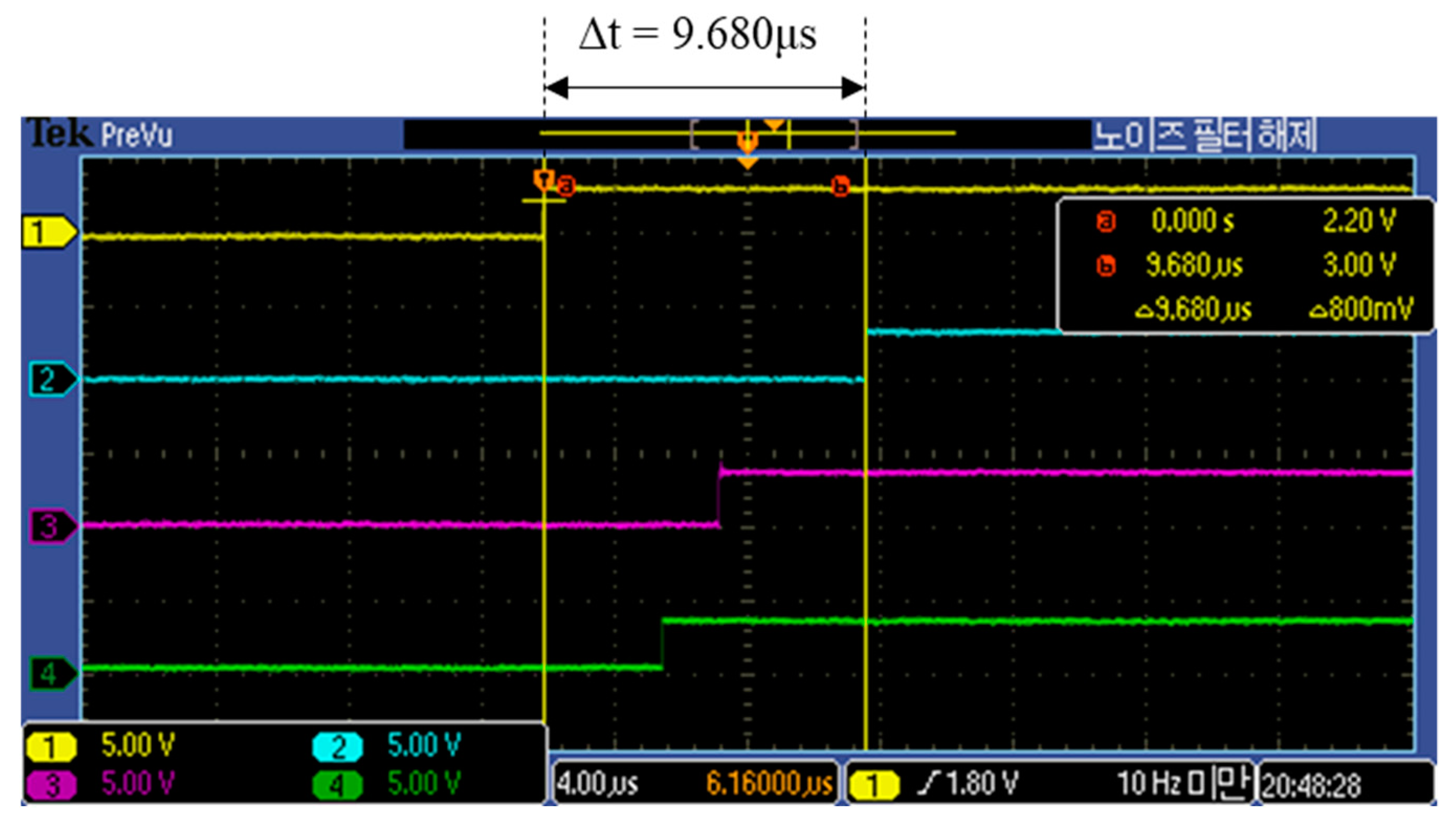
Figure 8 shows the oscilloscope measurement results of the synchronization error occurring in the four nodes after performing time synchronization in the CAN–Ethernet network. According to the measurements, when the proposed synchronization algorithm was applied, the maximum synchronization error between the master and slave was approximately 9.68 μs. Table 1 presents the synchronization error when the above experiment was repeated ten times. The average of the synchronization errors was approximately 8.18 µs, with a worst-case error of 9.68 μs. Although various factors can cause this error, the timestamp function, which measures and records time, is most likely to significantly influence this error, because it is operated by software.

5. Conclusions

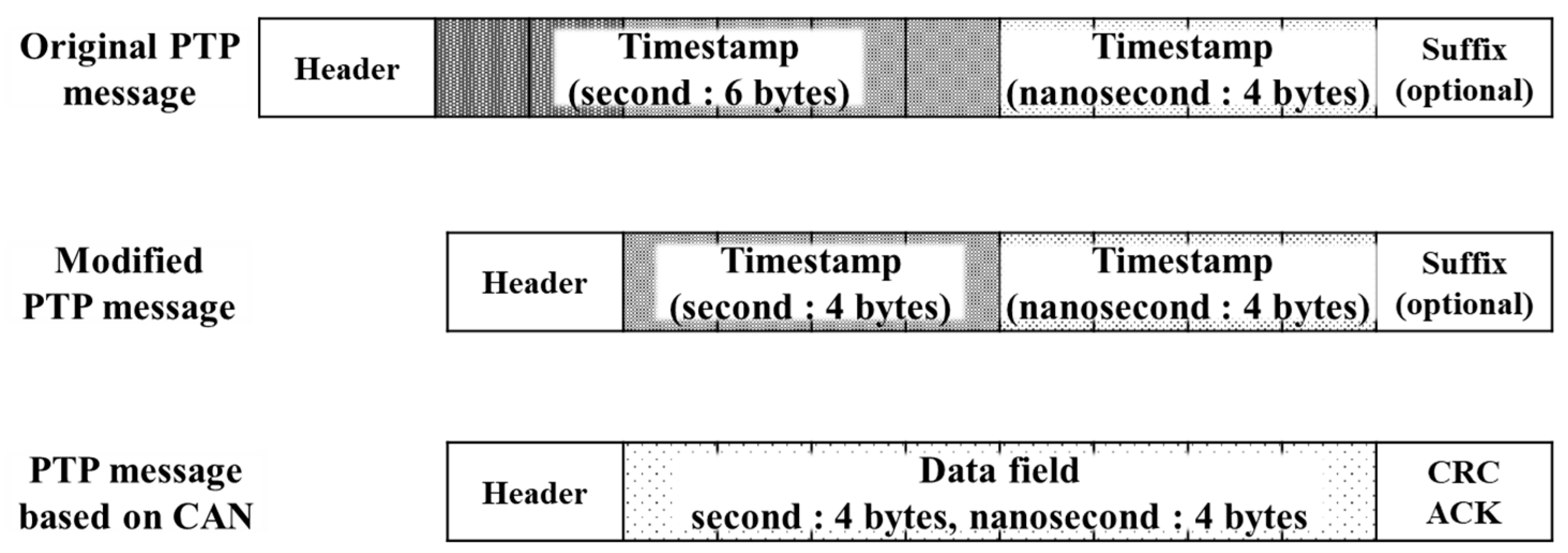
This study proposed a method for performing time synchronization on a CAN–Ethernet heterogeneous network connected by a gateway. In particular, the study proposed a time-synchronization method that considered the processing delay in the gateway required to convert the messages. Moreover, a synchronization method for CAN networks was proposed in which the slaves shared the calculated delay to simplify the procedure by exploiting CAN’s bus topology. In addition, the CAN message format was proposed to convey PTP messages over the CAN network. Finally, a test bed was constructed using automotive microcontroller modules, and used to evaluate the time- synchronization performance of the proposed method for heterogeneous CAN–Ethernet networks. The following conclusions may be drawn from the obtained results.
First, the synchronization method of IEEE 1588 was extended to develop a synchronization method for heterogeneous networks connected by a gateway. For this purpose, equations were derived to calculate the propagation delay and offset by considering the asymmetric processing time of the gateway. Furthermore, to implement the required synchronization technique, this study proposed a method that accommodates the maximum data size constraint of the CAN and the difference in bus transmission methods.
Second, the evaluation of synchronization performance demonstrated that the proposed method has an error of approximately 7 µs. While this does not satisfy the 1 µs error suggested in IEEE 1588, it indicates that the method can provide satisfactory synchronization precision for applications, such as autonomous driving, despite the use of software timestamps. Therefore, because the output of the sensors connected to the synchronized CAN nodes is measured within approximately 7 µs, it is expected to enhance context recognition performance via sensor fusion.
In terms of future research directions, follow-up studies may replace the software timestamps with hardware timestamps and experimentally verify the extent to which the system performance can be improved. Research is also required concerning methods to introduce the P2P method of IEEE 1588 and the selection of the appropriate CAN nodes to perform synchronization with the Ethernet master node. In addition, more research effort on synchronization should be directed to more complicated network structures such as Ethernet connected with tandem CAN networks and other types of heterogeneous networks, namely, CAN-MOST and CAN-FlexRay.

Author Contributions

Conceptualization, H.J.K. and U.L.; Project administration, S.L.; Software, H.J.K. and U.L.; Supervision, M.K.; Writing—original draft, H.J.K.; Writing—review & editing, M.K. and S.L. All authors have read and agreed to the published version of the manuscript.

Funding

This work was supported by the System Industrial Strategic Technology Development Program (10079961, “Development of a deterministic DCU platform with less than 1 μs synchronization for autonomous driving system control) funded By the Ministry of Trade, Industry & Energy (MOTIE, Korea).

Conflicts of Interest

The authors declare no conflict of interest.

References

  1. Park, H.Y.; Ahn, K.K.; Park, M.K.; Lee, S.H. Study on Robust Lateral Controller for Differential GPS-Based Autonomous Vehicles. Int. J. Prec. Eng. Manufac. 2018, 19, 367–376. [Google Scholar] [CrossRef]
  2. Park, I.S.; Sunwoo, M.H. FlexRay network parameter optimization method for automotive applications. IEEE Trans. Ind. Electron. 2011, 58, 1449–1459. [Google Scholar] [CrossRef]
  3. Uhlemann, E. Introducing Connected Vehicles. IEEE Veh. Technol. Mag. 2015, 10, 23–31. [Google Scholar]
  4. Jeong, Y.; Son, S.; Jeong, E.; Lee, B. An Integrated Self-Diagnosis System for an Autonomous Vehicle Based on an IoT Gateway and Deep Learning. Appl. Sci. 2018, 8, 1164. [Google Scholar] [CrossRef] [Green Version]
  5. Tuohy, S.; Glavin, M.; Hughes, C.; Jones, E.; Trivedi, M.; Kilmartin, L. Intra-Vehilce Network: A reveiw. IEEE Trans. Intell. Transp. Sys. 2015, 16, 534–545. [Google Scholar] [CrossRef]
  6. Kim, J.H.; Seo, S.H.; Hai, N.T.; Cheon, B.M.; Lee, Y.S.; Jeon, J.W. Gateway Framework for In-Vehicle Networks Based on CAN, FlexRay, and Ethernet. IEEE Trans. Veh. Technol. 2015, 64, 4472–4486. [Google Scholar] [CrossRef]
  7. Lian, F.L.; Moyne, J.; Tilbury, D. Network design consideration for distributed control systems. IEEE Trans. Control. Syst. Technol. 2002, 10, 297. [Google Scholar] [CrossRef]
  8. Tipsuwan, Y.; Chow, M.Y. Control methodologies in networked control systems. Control. Eng. Pract. 2003, 11, 1099–1111. [Google Scholar] [CrossRef]
  9. Youn, J.; Sunwoo, M.H.; Lee, W. A Study on Timing Modeling and Response Time Analysis in LIN Based Network System. Trans. Korean Soc. Automot. Eng. 2005, 13, 48–55. [Google Scholar]
  10. Babaev, S.; Singh, R.S.; Cobben, S.; Ćuk, V.; Downie, A. Multi-Point Time-Synchronized Waveform Recording for the Analysis of Wide-Area Harmonic Propagation. Appl. Sci. 2020, 10, 3869. [Google Scholar] [CrossRef]
  11. AUTOSAR 4.2.2. Specification of Synchronized Time Base Manager. AUTOSAR Std., 2015. Available online: https://www.autosar.org/fileadmin/user_upload/standards/classic/4-3/AUTOSAR_SWS_SynchronizedTimeBaseManager.pdf (accessed on 1 September 2020).
  12. AUTOSAR 4.2.2. Specification of Time Synchronization over CAN. AUTOSAR Std., 2015. Available online: https://www.autosar.org/fileadmin/user_upload/standards/classic/4-3/AUTOSAR_SWS_TimeSyncOverCAN.pdf (accessed on 1 September 2020).
  13. IEEE Std. 1588. Precision Clock Synchronization Protocol for Networked Measurement and Control Systems; IEEE Std: Piscataway, NJ, USA, 2002. [Google Scholar] [CrossRef]
  14. SAE Std. Time-Triggered Ethernet-AS6802; SAE Std: Englewood, CO, USA, 2016. [Google Scholar]
  15. FlexRay Specification. FlexRay Communications System Protocol Specification. version 2.0. FlexRay Consortium, 2004. Available online: https://www.dspace.com/en/inc/home/company/cooperations/standardizations/flexray_consortium.cfm (accessed on 1 September 2020).
  16. Zhao, L.; He, F.; Li, E.; Lu, J. Comparison of Time Sensitive Networking (TSN) and TTEthernet. In Proceedings of the 2018 IEEE 37th Digital Avionics Systems Conference, London, UK, 23–27 September 2018; pp. 1–7. [Google Scholar]
  17. Alshaikhli, A.O.; Rhee, J.M. TFR: A Novel Approach for Clock Synchronization Fault Recovery in Precision Time Protocol (PTP) Networks. Appl. Sci. 2018, 8, 21. [Google Scholar] [CrossRef] [Green Version]
  18. Park, S.W.; Kim, I.S.; Lee, D. Implementation of IEEE1588 of Clock Synchronization. Inf. Commun. Mag. 2014, 39, 123–132. [Google Scholar] [CrossRef] [Green Version]
  19. Lee, Y.S.; Kim, J.H.; Jeon, J.W. FlexRay and Ethernet AVB Synchronization for High QoS Automotive Gateway. IEEE Trans. Veh. Technol. 2017, 66, 5737–5751. [Google Scholar] [CrossRef]
  20. Tindell, K.; Burns, A.; Wellings, A. Calculating controller area network (CAN) message response times. Control. Eng. Pract. 1995, 3, 1163–1169. [Google Scholar] [CrossRef]
Figure 1. Time-synchronization mechanism of IEEE 1588 in (a) end-to-end and (b) peer-to-peer systems [13].
Applsci 10 08873 g001
Figure 2. End-to-end mechanism in a CAN–Ethernet network with a gateway.
Applsci 10 08873 g002
Figure 3. Comparison of the PTP message format in the CAN and Ethernet network.
Applsci 10 08873 g003
Figure 4. Synchronization algorithm of the master and slave nodes in the CAN–Ethernet network: (a) master node (Ethernet), (b) slave node (CAN), and (c) gateway.
Applsci 10 08873 g004
Figure 5. Synchronizing process for sharing the delay.
Applsci 10 08873 g005
Figure 6. Experimental environment for the evaluation of synchronization in the CAN–Ethernet network.
Applsci 10 08873 g006
Figure 7. Comparison of the trigger signals before and after synchronization.
Applsci 10 08873 g007
Figure 8. Evaluation results of the synchronization in the CAN–Ethernet network.
Applsci 10 08873 g008
Table 1. Evaluation results of the synchronization in the CAN–Ethernet network.
Number of EvaluationsTime Deviation (µs)Number of EvaluationsTime Deviation (µs)
17.8467.60
29.6877.76
37.0488.64
49.2898.08
56.48109.44
Publisher’s Note: MDPI stays neutral with regard to jurisdictional claims in published maps and institutional affiliations.

