Article

Bio-Inspired Dielectric Resonator Antenna for Wideband Sub-6 GHz Range

1
Politecnico di Bari, Dipartimento di Ingegneria Elettrica e dell’Informazione, Via E. Orabona 4, 70125 Bari, Italy
2
STIIMA CNR, Institute of Intelligent Industrial Technologies and Systems for Advanced Manufacturing, National Research Council, Via P. Lembo, 38/F, 70124 Bari, Italy
*
Authors to whom correspondence should be addressed.
Appl. Sci. 2020, 10(24), 8826; https://doi.org/10.3390/app10248826
Submission received: 10 November 2020 / Revised: 27 November 2020 / Accepted: 7 December 2020 / Published: 10 December 2020
(This article belongs to the Section Electrical, Electronics and Communications Engineering)

Abstract

:
Through the years, inspiration from nature has taken the lead for technological development and improvement. This concept firmly applies to the design of the antennas, whose performances receive a relevant boost due to the implementation of bio-inspired geometries. In particular, this idea holds in the present scenario, where antennas working in the higher frequency range (5G and mm-wave), require wide bandwidth and high gain; nonetheless, ease of fabrication and rapid production still have their importance. To this aim, polymer-based 3D antennas, such as Dielectric Resonator Antennas (DRAs) have been considered as suitable for fulfilling antenna performance and fabrication requirements. Differently from numerous works related to planar-metal-based antenna development, bio-inspired DRAs for 5G and mm-wave applications are at their beginning. In this scenario, the present paper proposes the analysis and optimization of a bio-inspired Spiral shell DRA (SsDRA) implemented by means of Gielis’ superformula, with the goal of boosting the antenna bandwidth. The optimized SsDRA geometrical parameters were also determined and discussed based on its fabrication feasibility exploiting Additive Manufacturing technologies. The results proved that the SsDRA provides relevant bandwidth, about 2 GHz wide, and satisfactory gain (3.7 dBi and 5 dBi, respectively) at two different frequencies, 3.5 GHz and 5.5 GHz.

1. Introduction

The use of peculiar geometries and shapes inspired by nature has demonstrated, through the years, to be an intriguing and successful option capable of supporting the development of advanced electronic devices. In particular, these bio-inspired designs are able to cope with the main criticalities related to metal-based antenna systems aimed at WLNA, WiMAX, 5G and mm-wave communication applications: wide bandwidth and high radiation efficiency. In this viewpoint, Panda et al. [1] presented the design of a microstrip antenna resembling a flower shape, conceived on a defective ground structure (DGS); the numerical results showed that a dramatic improvement of the bandwidth and return loss was achieved at the operating frequency (15 GHz). Abolade et al. [2] exploited the shape of Carica Papaya leaf to realize a microstrip antenna which exhibited large bandwidth and high gain for three different bands, centered at 4.3 GHz, at 7.2 GHz and 9.3 GHz, respectively, providing a compact and suitable solution for a variety of applications (GSM1900, UMTS, WLAN, LTE2300 and LTE2600, WiMAX, C-band, X-band, and sub-6GHz band). A patch antenna patterned as sunflower seeds was proposed by Singh et al. [3] to obtain omni-directional radiation properties and increased radiation efficiency between 14 and 15 GHz. Mesquita et al. [4] exploited the Oxalis triangularis plant’s leaf shape for the design and fabrication of two frequency selective surface (FSS) microstrip arrays, where the conductive elements were realized by using copper and silver ink. The results showed that the fractional bandwidth was equal to 18% for copper and 14% for silver ink, at the central resonant frequency (2.5 GHz). De Oliveira et al. [5] applied a four-leaf clover geometry to the patch elements of an array designed for wireless application, in the frequency band of 2.45 GHz. The results concerned an achieved bandwidth of 81 MHz and a maximum gain of 8.24 dBi at 2.4 GHz. Fractal based wideband microstrip antenna, conceived for 5G applications, was proposed by Malik et al. [6]: the optimized structure was characterized by a fractional bandwidth of 165% in the frequency range from 17.22 GHz to 180 GHz, with a peak gain of 10 dBi; additionally, the antenna exhibited relevant compactness in size. Self-similar fractals have been used to create multi-band antennas [7,8] and also antennas based on genetic evolution have been proposed to design high-directive antennas [9].
The opportunity to design more and more bio-inspired geometries became effectively available when Gielis introduced his superformula [10,11]. Since then, this superformula has been widely exploited to design patch antennas [12,13,14], metamaterial and metasurfaces [15,16], frequency selective surfaces (FSS) [17], split-ring resonators [18,19], wearable antennas [20] and, very recently, Dielectric Resonator Antennas (DRAs) [21,22].
Concerning patch antennas, the superformula was used by Poordaraee et al. [12] to implement the characteristic mode theory with the goal of designing and modifying patch antennas’ shapes and obtain circularly polarized radiated field at 2.45 GHz for ISM band application. Two designs of UWB coplanar waveguide (CPW)-fed-patch antennas designed by means of Gielis’ superformula and operating in the FCC frequency band (3.1–10.6 GHz) were proposed by Omar et al. [13]. In particular, in this work, it was shown that the super-shaped sawtooth-like circumference patch allowed to have same bandwidth (600 MHz) and gain (3.8 dBi) at the central frequency (7 GHz) of the classic circular patch; the main advantage of using such shapes consisted in a smaller patch diameter. The same compactness in the antenna size was accomplished by Naser and Dib [14], who designed an ultra-wideband microstrip-fed patch antenna, working between 3.1 GHz–10.6 GHz, by using a contour profile based on the superformula.
Although plenty of works about bio-inspired geometries can be easily found for planar microstrip antenna technology, very few examples are proposed for dielectric-based antennas, such as DRAs. DRAs are successfully exploited for the design of dielectric metasurfaces, which are of paramount importance at very high frequencies, i.e., in the optical domain. Indeed, they can be used for polarization manipulation to design polarization converters [23], beam splitters [24], and polarization-based functional metalenses [25]. Another possibility is to use them for polarization detection [26] or polarization-based nano-printing [27].
As for their relevant inclination for high-frequency purposes, DRAs are currently recommended by the research community for 5G and mm-wave applications: indeed, as these structures are made of dielectric materials, they are free of conduction losses and, as such, capable of fulfilling bandwidth and radiation efficiency requirements. Additionally, as DRAs can be also made of polymers, they can be easily fabricated by means of Additive Manufacturing (AM) technologies.
Very recently, optimized DRAs made of low permittivity materials providing wider bandwidth were proposed. An evaluation of dielectric materials suitable for microwave range applications was reported by Kumar and Gupta [28], who focused mainly on types of Rogers and FR4. Nonetheless, also polymers, such as polyactic Acid (PLA), were considered for the design and manufacturing of DRAs featuring simple 3D geometries [29,30]. However, although very promising for wideband specification, low permittivity—DRAs are often characterized by low radiation efficiency. Therefore, the scientific community recently focused on the use of more intricate and complex 3D geometries, such as 3D quadrupole-shaped [31,32], for WLAN (8 GHz) and 5G applications (3.5 GHz). An attempt of using bio-inspired geometry was presented by Sankaranarayanan et al. [33]: in this work, snow-flake fractal and half split fractal rings were implemented on the classic cylindrical DRAs, thus achieving 90% of fractional bandwidth and gain enhancement in the frequency range between 4.7 and 12.4 GHz. Fractal segmented patterns were also employed by Gupta et al. [34] to design FR4-based DRAs with ultra-wideband performance (122.5% and 94.89%) from 4.8 GHz to 20 GHz and characterized by high compactness and gain at 8.5 GHz (8.75 and 15.65 dBi, respectively). Actual 3D star-super-shaped DRAs (S-DRAs) based on Gielis’ superformula were reported by Simeoni et al. [35], Petrignani et al. [36] and Basile et al. [37]. In [35], the super-shaped DRAs (S-DRA) were designed to operate at 7.65 GHz and realized by considering polyvinyl chloride (PVC), a thermoplastic material having low permittivity (εr~2.8) and negligible tangent loss. The results showed that in the single feed case study, a fractional bandwidth of 74% and gain of ~8 dBi were accomplished between 6 and 13 GHz. Conversely, in [36,37], twisted star-based S-DRAs were designed to operate in the sub-6 GHz range, at 3.5 GHz. The S-DRAs were realized by means of a photopolymer resin material having εr = 2.7 and low tangent loss, suitable for stereolithography. The experimental results showed that this kind of DRAs was able to provide high gain (around 3 dBi) and radiation efficiency (~90%) at 3.5 GHz, while keeping their volume significantly small.
However, although the use of bio-inspired geometry and DRAs proved to lead to an overall improvement of the antenna performance, especially in terms of bandwidth enhancement, works about the actual combination of these two strategies for a further boost in the antenna development are still at their beginning. Indeed, very few Authors attempted to design and realize bio-inspired DRAs and, in particular, none of them considers complex and thin 3D shapes, like Button snail Modulus modulus (spiral seashell) for the DRA applications.
Therefore, in this research, the design and optimization of a bio-inspired super-shaped DRA, resembling a Spiral shell of a sea mollusk, generated by means of Gielis’ superformula and suitable for sub-6 GHz applications, is presented. The numerical analyses were performed by fixing Gielis’ parameters and varying the geometrical sizes of the DRA, with the aim of accomplishing wideband behavior in the frequency range of interest. In particular, the influence of the coaxial cable pin height, DRA thickness and height on the scattering parameter S11 and antenna gain are evaluated. The impact of the exponential coefficient of Gielis’ superformula on the antenna design was also investigated in terms of antenna design and prototype fabrication, envisaged to be realized by means of Additive Manufacturing processes. The 3D radiation patterns, electric and magnetic field distributions and radiation efficiency of the optimized Spiral shell DRA are also reported. The overall performance of the SsDRA was then compared to other DRA geometries, conceived and realized by using the same low-permittivity material. Finally, a detailed discussion about fabrication feasibility and issues emerged for the realization of the Ss-DRA prototype is reported.

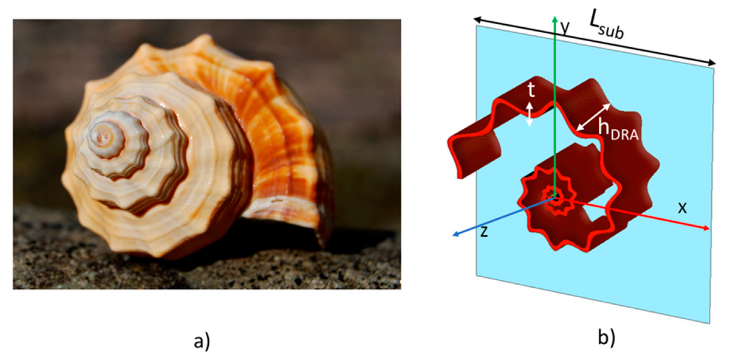
2. Bio-Inspired Spiral Shell DRA

The Button snail Modulus modulus (spiral seashell) presented in Figure 1a was the bio-inspiration for the device of the SsDRA shown in Figure 1b. The SsDRA is placed in the center of a ground plane, a squared substrate with side LSUB, in the origin of the reference system; the dielectric thickness t and the height hDRA of the antenna are also indicated. The considered dielectric material has a permittivity of 2.7 and negligible loss tangent (0.008) in the frequency range of interest [36,37]. The DRA is fed by a coaxial cable (Z0 = 50 Ω, conductor diameter Ø 0.48 mm, insulation diameter Ø 1.52 mm) placed in the antenna origin: the pin height is indicated by hPIN.
The shape of the SsDRA was generated by Gielis’ superformula explicated in Equation (1) [38]:
GT ( θ ,   f ( θ ) ,   a ,   b ,   m 1 ,   m 2 ,   n 1 ,   n 2 ,   n 3 ) = K · f ( θ ) · [ | 1 a cos ( m 1 4 θ ) | n 2 + | 1 b sin ( m 2 4 θ ) | n 3 ] 1 / n 1

2.1. Gielis Parameters: Impact on the SsDRA Design

The design initiator was defined by considering that the variation of the “a” and “b” parameters affects the sizes and volume of the DRA, and so the footprint it can actually occupy. The angular position of the shell wave ridges remains constant, while the shell wave amplitudes increase proportionally as “a” and “b” increase. The “m1” and “m2” parameters influence the frequency of the shell wave over the base spiral: when these coefficients are increased, the shell wave number increases along the spiral. The parameters “n1”, “n2” and “n3” affect the shell wave amplitude on each loop of the shell: in particular, when n1 = n2 = n3 = 2, the output geometry becomes the well-known Archimedean spiral. For values of “n1”, “n2” and “n3” higher than 2, alternate waves are overlapped on the spiral. When these parameters are lower than 2, the waves resemble a rectified sine (or cosine) with an outward concavity, thus orienting the wave ridges inward. The constant scaling factor K regulates the overall amplitude of the geometry and, as such, it affects the DRA radius and volume. The planar exponential function f ( θ ) ,   expressed by the following Equation (2):
f ( θ )   =   e   ( c theta *   θ )
acts on the closeness of the wavy spiral loops, thus on the space actually filled by the DRA. In particular, the parameter ctheta (which is a rational number) has a sharp influence on the radial expansion of the spiral loops, i.e., the aperture velocity ΔR/Δθ.
On the basis of these considerations, we fixed the starting initiator values reported in Table 1 where the angle parameter θ is varied in the range [−3π, 3π] (i.e., three complete rounds).
The defined parameters lead to a SsDRA footprint smaller than the ground plane whose dimensions are 100 × 100 mm2, thus with LSUB = 100 mm.

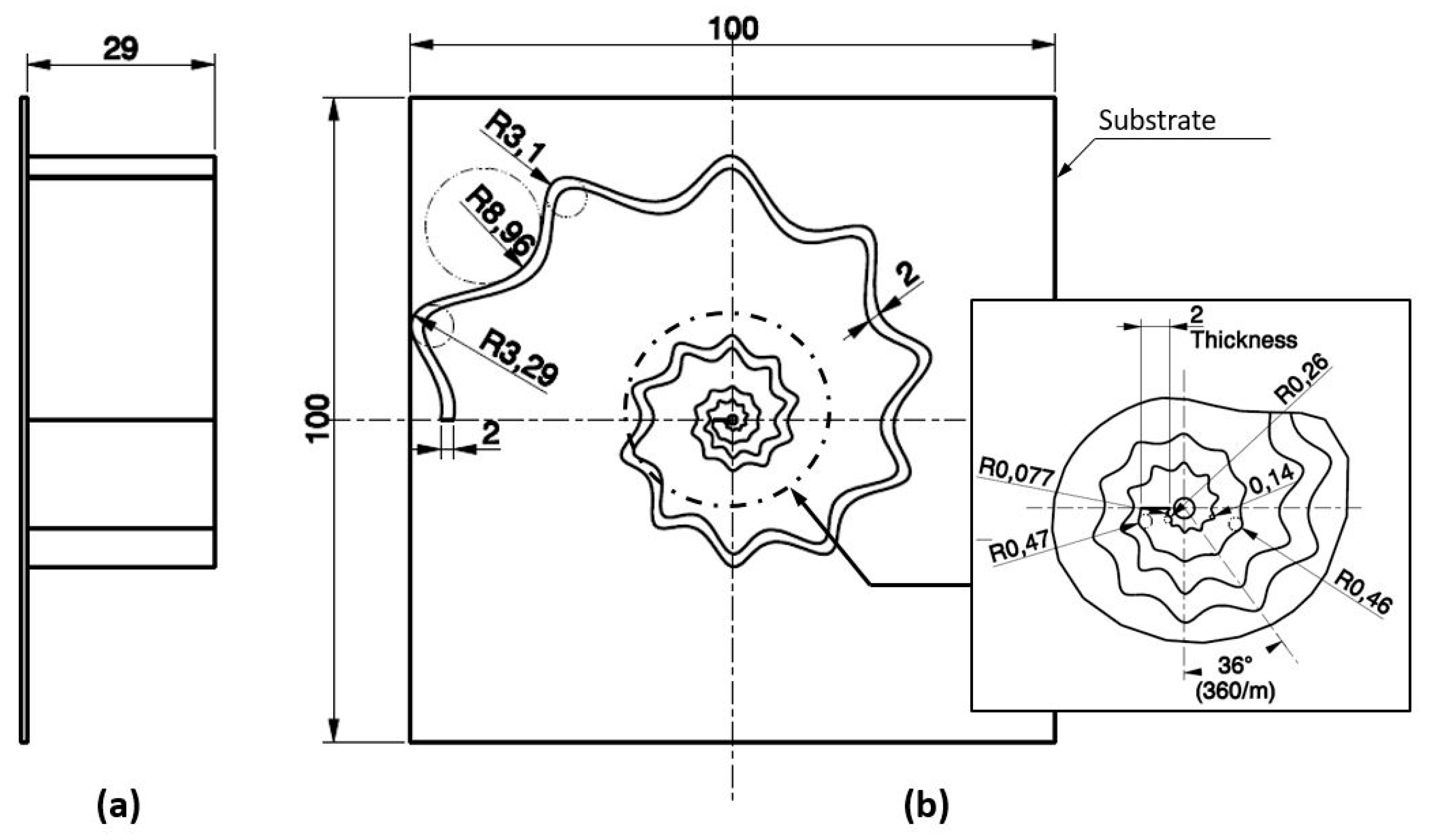
2.2. Evaluation of SsDRA Design Based on the Fabrication Feasibility

The proposed SsDRA has a typical 2.5D geometry, since it develops as a straight protrusion of a thin planar section. The main fabrication issue displayed along the z-axis direction concerns the aspect ratio (AR) of the geometry, defined as hDRA/t. In order to guarantee the successful fabrication of a stiff structure, the AR should be higher than a critical threshold, which depends on the mechanical properties of the material and the chosen fabrication technology. Therefore, in the antenna optimization, the values of t and hDRA were set by taking into account this limitation.
The spiral section evolving along the X-Y plane represents the main challenge for the fabrication of the proposed geometry, and, as such, it dictates the actual selection of the most suitable Additive Manufacturing process. In order to come up with feasible solutions for the further SsDRA fabrication, preliminary considerations were made, basing on the SsDRA prototype drawings reported in Figure 2, as follows:
  • By fixing the parameter “m” equal to 10, the geometry has 10 peaks and valleys and the step-angle between them is kept constant and equal to 36 degrees (360/m), independently of the position along the spiral curve. Ridges and valleys are rounded, but the lower the cylindrical coordinate θ (and distance from the origin GT(θ)) is, the lower the radius of the circle which approximates locally the curve on ridges or valleys. In addition, the amplitude of the oscillation along the spiral is proportional to the values of parameters n1, n2 and n3 of the Gielis formulation (1): in this case, they are all equal to 5. This setting allows us to have smaller amplitude close to the origin, i.e., micro-features which requires an accurate fabrication assessment.
  • Since the radius of the spiral increases monotonically from the origin to the end of the spiral, the smaller features of the geometry are in close proximity to the origin, thus generating micro-scale features.
The measurement of circle approximations of the curve is important to evaluate the feasibility of 3Dprinting technologies in the SsDRA fabrication. Indeed, the majority of the Additive Manufacturing technologies build the objects using a layer-by-layer strategy, accomplished by moving a circular end-effector: in particular, the end-effector is an extrusion nozzle in the Fused Deposition Modelling (FDM), and a laser spot in the stereolithography (SLA) [39,40]. Therefore, the previous considerations lead to select an AM process that should be capable of reproducing accurately the micro-features and ensuring the target value of roundness for the ridges and valleys. Detailed discussions about the evaluation of the best candidate among AM processes along with fabrication challenges and solutions about the optimized SsDRA fabrication are reported in Section 4.

3. Spiral Shell DRA Analysis and Optimization

In order to evaluate the SsDRA performance and proceed with the antenna optimization, numerical analyses have been carried out on the SsDRA geometrical parameters by means of the CST Microwave Studio.

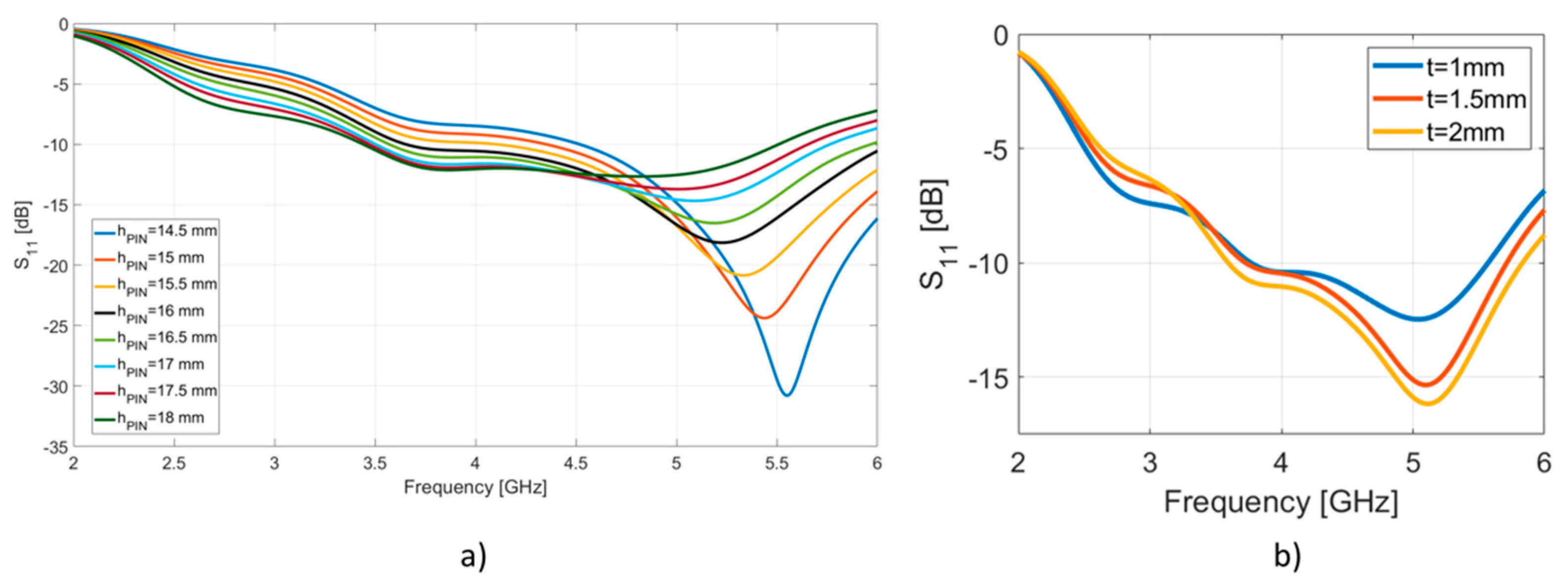
3.1. Influence of SsDRA Thickness, Pin Height and SsDRA Height on the Scattering Parameter S11: Evaluation of the Bandwidth

In order to optimize the SsDRA design in terms of bandwidth, the scattering parameter S11 was evaluated by varying the central pin height, hPIN, and the SsDRA shell thickness t, by fixing the SsDRA height hDRA = 29 mm. The pin height hPIN is changed between 14.5 and 18 mm, while keeping the DRA thickness equal to t = 2 mm. The trend of the scattering parameter S11 as a function of hPIN is reported in Figure 3a, where it can be noticed that when the pin height increases, the impedance matching becomes wider. In particular, for a pin height hPIN = 17 mm (cyan curve), a good impedance matching can be achieved at 3.5 GHz and 5.5 GHz, leading to a bandwidth of about 2 GHz. Figure 3b depicts the trend of the scattering parameter S11 when hPIN is fixed at 17 mm and the SsDRA thickness t is varied (t = 1, 1.5 and 2 mm). The plots show that as t increases, the scattering parameter S11 values improve, especially at 5.2 GHz, and, when t = 2 mm (yellow curve), the bandwidth at −10 dB is equal to about 2 GHz.

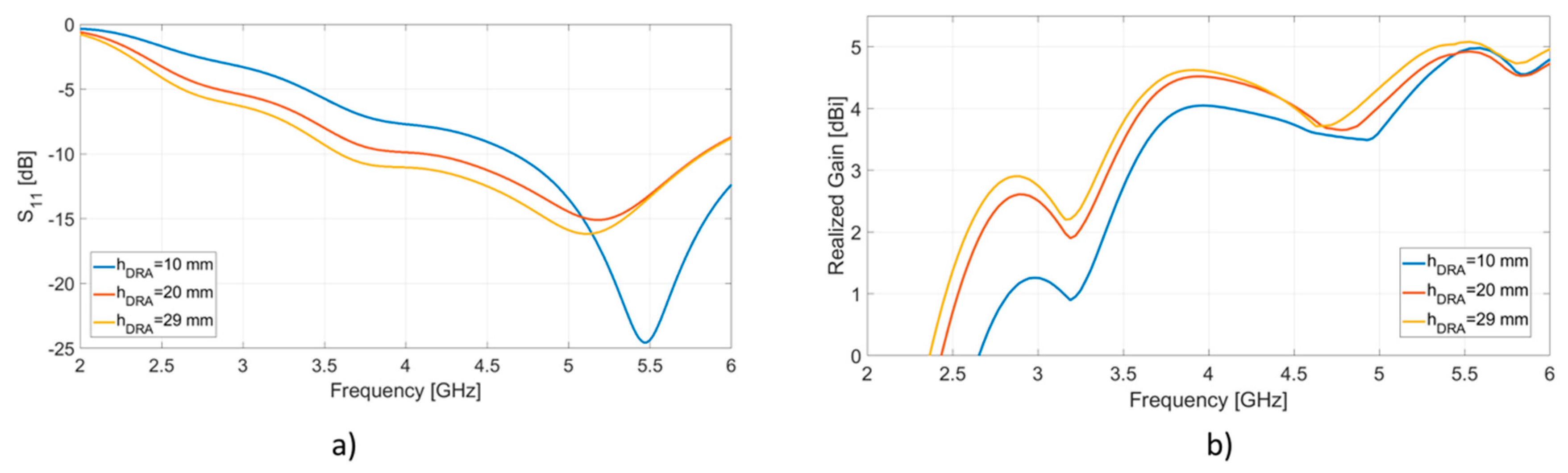
3.2. Effect of the SsDRA Thickness, Pin Height and DRA Height on the Scattering Parameter S11 and Realized Gain

Figure 4a shows the scattering parameter S11 when both hPIN and t are varied, while hDRA is set equal to 29 mm; the behavior of the monopole antenna (blue curve) having a pin height hPIN equal to 17 mm is also reported for reference. The monopole exhibits a scattering parameter S11 value of about −14 dB at about 5.7 GHz with a bandwidth of about 1 GHz (from 4 GHz to 5 GHz). When the SsDRA is considered and its thickness t is increased, a better impedance matching is accomplished: in particular, the antenna bandwidth at −10 dB increases from 1.5 GHz for t = 1 mm and hPIN = 19 mm (red curve), up to about 2 GHz for t = 2 mm and hPIN = 17 mm (purple curve), along with lower scattering parameter S11 value (−16 dB), especially around 5.2 GHz.
Figure 4b depicts the realized gain of the antenna that takes into account the losses due to the matching: as we can infer from the plot, as the SsDRA thickness is increased, gain values are equal to 3.3 dBi at 2.8 GHz (red curve), and increase up to 5 dBi at 5.5 GHz (purple curve). Generally, the gain values improve by about 0.2 dB up to about 2 dB with respect to the reference monopole in the overall frequency range of interest. Furthermore, the inspection of Figure 4b shows that SsDRA allows the additional coverage of the WiFi band, at 2.45 GHz.
Figure 5 reports the evaluation of the scattering parameter S11 and gain as the SsDRA height hDRA is varied between 10 mm and 30 mm, while hPIN and t are fixed to 17 mm and 2 mm, respectively. As evident from Figure 5a, when the SsDRA height is increased from 10 mm and 20 mm, the bandwidth at −10 dB increases as well, covering a range from about 1.3 GHz to 1.8 GHz (red and yellow curves). Conversely, as shown in Figure 5b, as the hDRA is increased, the SsDRA gain improves in the range between 2.5 GHz to 4.5 GHz (red and yellow curves are relevantly higher than the blue curve), while it shows negligible changes around 5.5 GHz.

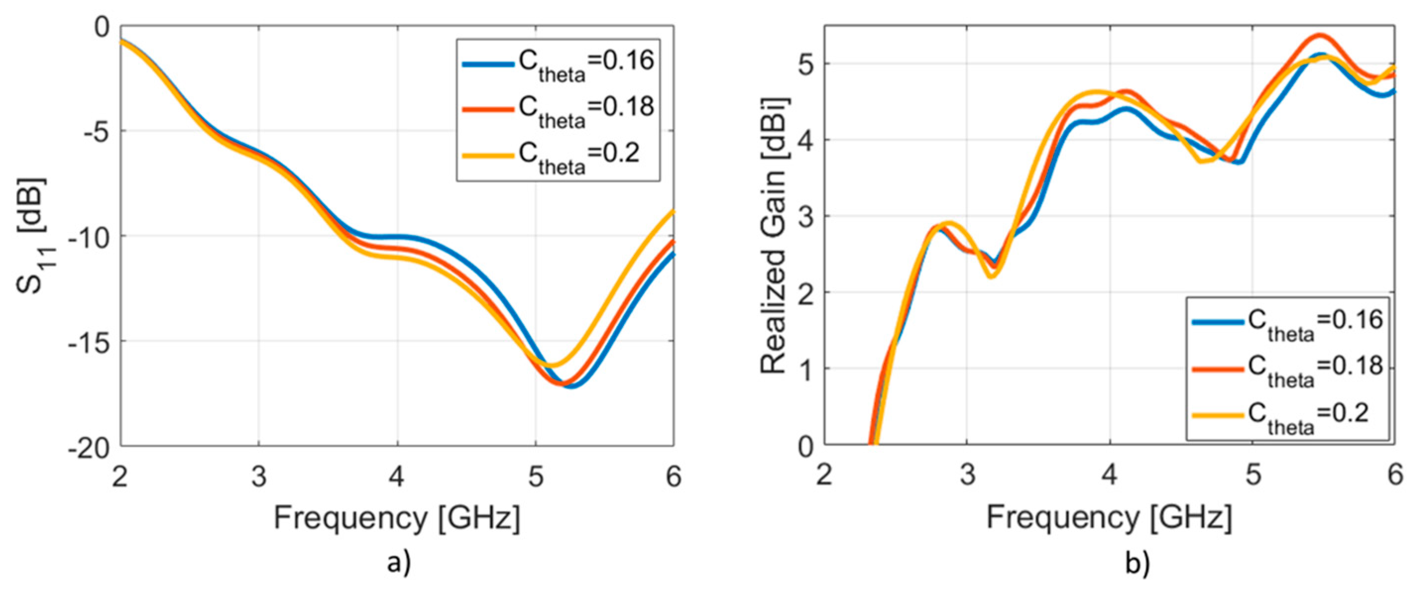
3.3. Scattering Parameter S11 and Realized Gain as a Function of the Exponential Function f(θ) of the Optimized SsDRA

In order to show the effect of the planar exponential function f(θ) on the SsDRA performance, the coefficient ctheta was varied by considering three values: 0.16, 0.18 and 0.20. The geometrical sizes of the SsDRA were kept unchanged: t = 2 mm, hDRA = 29 mm and hPIN = 17 mm. Figure 6a reveals that, when this coefficient is reduced, the lower cut-off frequency shifts at higher frequencies (from 3.5 GHz to about 4 GHz), while the minimum of the scattering parameter shifts from 5 GHz to 5.5 GHz. Figure 6b shows that when ctheta is reduced, the antenna gain undergoes a reduction at 3.5 GHz (blue curve), while it exhibits a slight increase (about 0.4 dB) at 5.5 GHz (red curve).
Finally, we underline that, if θ is varied in the range 0–2π (1 complete round), while other parameters are fixed—t = 2 mm, hDRA = 29 mm, hPIN = 17 mm and ctheta = 0.2—the SsDRA bandwidth experiences a significant reduction, decreasing down to about 1.5 GHz, while the realized gain value approaches the monopole one, in the frequency interval from 4.5 GHz to 6 GHz.

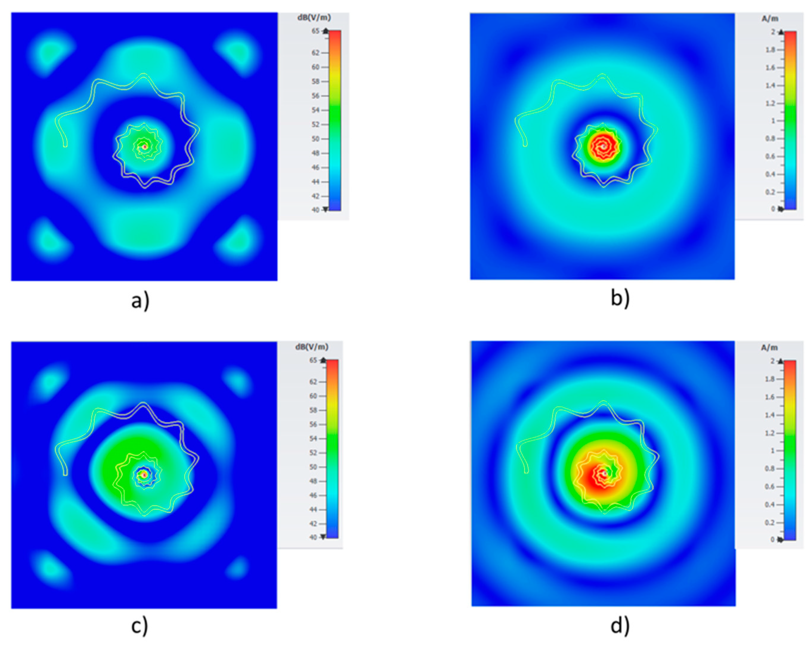
3.4. Radiation Pattern, Realized Gain and Radiation Efficiency of the Optimized SsDRA

The previous analyses allowed to define the geometrical parameters of the bio-inspired SsDRA which exhibits wider bandwidth and a satisfactory gain value at two frequencies, 3.5 GHz and 5.5 GHz: t = 2 mm, hDRA = 29 mm, hPIN = 17 mm and ctheta = 0.2.
Figure 7 shows the 3D radiation patterns of the optimized antenna, along with the polar cuts in the E and H planes, at 3.5 GHz and 5.5 GHz. In particular, when the frequency is equal to 3.5 GHz (Figure 7a–c), the maximum value of the gain is equal to 3.78 dBi. The main lobe magnitude in the E-plane (φ = 0 deg, Figure 7b) is equal to 0.727 dBi, the main lobe direction is equal to 53 deg and the angular width (3 dB) is equal to 82.7 deg. Conversely, when the H-plane is considered (φ = 90 deg, Figure 7c), the main lobe magnitude is equal to 1.05 dBi, while the main lobe direction is equal to 53 deg, with an angular width (3 dB) of 76.3 deg. Figure 7d–f plot the 3D radiation patterns and far-field radiation patterns of the optimized antenna at 5.5 GHz. In particular, in Figure 7e referring to E-plane, the maximum gain value is equal to 5.08 dBi, the main lobe magnitude at φ = 0 deg is equal to 3.91 dBi and the main lobe direction is equal to 61.0 deg with an angular width (3 dB) of 52.5 deg. In the H-plane (Figure 7f), for φ = 90 deg, the main lobe magnitude is equal to 4.22 dBi, the main lobe direction is equal to 61.0 deg and the angular width (3 dB) is equal to 50.4 deg.
The electric field and the magnetic field intensities of the optimized SsDRA at 3.5 GHz and 5.5 GHz are displayed in Figure 8. The higher intensity is recorded at the coaxial cable pin, but larger part of it is distributed throughout the whole available SsDRA volume. As noticeable, at 3.5 GHz, both the electric field (Figure 8a) and the magnetic field (Figure 8b) intensities are symmetric with respect to the pin while, at 5.5 GHz, the electric field (Figure 8c) and the magnetic field (Figure 8d) intensities follow the dielectric resonator shape. In particular, in this last case, both intensities are located between the second and third loops of the shell. The analysis of the axial ratio reveals that the antenna shows a linear polarization as for the monopole over the frequency range of interest.
The radiation efficiency calculated for the optimized SsDRA is reported in Figure 9: the antenna exhibits an efficiency of about 45% around 3.5 GHz, while it increases up to about 85% at 5.5 GHz.

4. Discussion

The following Table 2 reports a comparison summarizing the performances obtained by numerical results of different DRAs, such as cylindric (C-DRA), rectangular (R-DRA), star-shaped (S-DRA) and Spiral shell (SsDRA). All antennas were modelled by considering the same low-permittivity material, Resin V04, suitable for stereolithography [36,37]. As noticeable, the optimized SsDRA displays relevant wider bandwidth behavior in the sub-6GHz range compared to other geometries, and it also covers two frequency bands, 3.5 GHz and 5.5 GHz. Additionally, good gain values are calculated at both frequencies, despite the significant reduction of dielectric material volume used for the antenna realization. In this viewpoint, the choice of bio-inspired geometry allows us to have bandwidth improvement, without affecting gain, yet reducing the required material quantity.
Concerning the realization of a prototype, if the antenna was thinner than 2 mm and taller than 29 mm, the antenna would be structurally weak. Therefore, the set t and hDRA values set the threshold corresponding to an aspect ratio AR = 14.5, enabling the actual realization of the antenna and ensuring its structural robustness. Additionally, referring to Figure 2, it can be noticed that, at the end of the spiral, the bigger circle, which approximates the curve, has a radius of about 9 mm, while the smaller circle in the proximity of the origin has a radius equal to 77 μm. This minimum round radius represents the actual fabrication challenges also for 3Dprinting technology. As the technology feature resolution is defined by the diameter of the circular end-effector and being the minimum required radius equal to 77 μm, this turns into a minimum end-effector diameter of De-e_min=2 * R = 154 μm. This consideration allows us to conclude that the SsDRA geometry cannot be feasible for the FDM process, as the majority of FDM machines are typically equipped with nozzle diameters of 200 μm or 400 μm. However, the SLA technology can be successfully exploited for the fabrication of the optimized SsDRA, as the laser spot diameter of the machine allows us to accomplish a micro-feature resolution of 85 μm [37].

5. Conclusions

In this work, the design of a bio-inspired Spiral shell DRA (SsDRA) implemented by means of Gielis’ superformula was proposed. The antenna was thoroughly optimized by properly setting Gielis’ superformula parameters considering two aspects: antenna performance and fabrication feasibility via Additive Manufacturing processes. In particular, the numerical analysis shows that optimized SsDRA exhibits very wide bandwidth behavior, up to 2 GHz, comprising two main frequencies: 3.5 GHz and 5.5 GHz. This characteristic made the proposed SsDRA feasible for applications in the sub-6GHz range. Moreover, the calculated gain is satisfactory, as 3.7 dB can be found at 3.5 GHz, while a gain of 5 dB is calculated at 5.5 GHz. From the fabrication viewpoint, the evaluation of the optimized SsDRA design proved that an accurate AM process is required to realize the micro-features characterizing the spiral rounds of the antenna; in particular, as the minimum size exhibited by the design is in the order of few tens of microns, stereolithography (SLA) is the best candidate to fabricate the SsDRA prototype.

Author Contributions

Conceptualization, L.M. and M.G.; software, L.M., I.M., G.N. and M.G.; investigation, L.M., I.M., G.N.,V.B., V.M., A.D. and M.G.; writing—original draft preparation, L.M., I.M., G.N., V.M., V.B., A.D. and M.G.; writing—review and editing, I.M., G.N., V.M., A.D. and M.G.; supervision and project administration, A.D. and M.G. All authors have read and agreed to the published version of the manuscript.

Funding

This research received no external funding.

Conflicts of Interest

The authors declare no conflict of interest.

References

  1. Panda, R.A.; Kumari, P.; Naik, J.; Negi, P.; Mishra, D. Flower Shaped Patch with Circular Defective Ground Structure for 15 GHz Application. In Innovations in Bio-Inspired Computing and Applications; IBICA 2019, Advances in Intelligent Systems and Computing, 1180; Abraham, A., Panda, M., Pradhan, S., Garcia-Hernandez, L., Ma, K., Eds.; Springer: Cham, Germany, 2019. [Google Scholar] [CrossRef]
  2. Abolade, J.O.; Konditi, D.B.O.; Dharmadhikary, V.M. Bio-inspired wideband antenna for wireless applications based on perturbation technique. Heliyon 2020, 6, e04282. [Google Scholar] [CrossRef] [PubMed]
  3. Singh, P.; Ray, K.; Rawat, S. Analysis of Sun Flower Shaped Monopole Antenna. Wirel. Pers. Commun. 2019, 104, 881–894. [Google Scholar] [CrossRef]
  4. Mesquita, M.D.S.; D’Assunção, A.G.; Oliveira, J.B.L.; Batista, Y.M.V. A New Conductive Ink for Microstrip Antenna and Bioinspired FSS Designs on Glass and Fiberglass Substrates. J. Microw. Optoelectron. Electromagn. Appl. 2019, 18, 227–245. [Google Scholar] [CrossRef]
  5. de Oliveira, M.A.; da Costa, A.P.; Forte, G.G.S.; de Melo, P.-K.P.; Fontgalland, G.; Silva, P.-H.F.; Fontgalland, I.L. Using polar transformation to design a dissimilar antenna array inspired on four-leaf clover. In Proceedings of the 2018 IEEE Radio and Wireless Symposium (RWS), Anaheim, CA, USA, 15–18 January 2018; pp. 228–230. [Google Scholar] [CrossRef]
  6. Malik, R.; Singh, P.; Ali, H.; Goel, T. A Star Shaped Superwide Band Fractal Antenna for 5G Applications. In Proceedings of the 2018 3rd International Conference for Convergence in Technology (I2CT), Pune, India, 6–8 April 2018; pp. 1–6. [Google Scholar] [CrossRef]
  7. Anguera, J.; Puente, C.; Borja, C.; Soler, J. Fractal-Shaped Antennas: A Review. In Wiley Encyclopedia of RF and Microwave Engineering; Chang, K., Ed.; John Wiley & Sons, Inc., 2005; Volume 2, pp. 1620–1635. [Google Scholar]
  8. Song, C.T.P.; Hall, P.S.; Ghafouri-Shiraz, H.; Wake, D. Sierpinski Monopole Antenna with Controlled Band Spacing and Input Impedance. IEE Electron. Lett. 1999, 35, 1036–1037. [Google Scholar] [CrossRef]
  9. Jayasinghe, J.W.; Anguera, J.; Uduwawala, D.N. A High-Directivity Microstrip Patch Antenna Design by Using Genetic Algorithm Optimization. Prog. Electromagn. Res. C 2013, 37, 131–144. [Google Scholar] [CrossRef] [Green Version]
  10. Gielis, J. A generic geometric transformation that unifies a wide range of natural and abstract shapes. Am. J. Bot. 2003, 90, 333–338. [Google Scholar] [CrossRef]
  11. Gielis, J. Method and Apparatus for Synthesizing and Analyzing Patterns Utilizing Novel “Super-Formula” Operator. U.S. Patent US7620527B1, 17 November 2009. [Google Scholar]
  12. Poordaraee, M.; Oraizi, H.; Khajevandi, S.; Glazunov, A.A. Systematic Design of a Circularly Polarized Microstrip Antenna Using a Shape Super-Formula and the Characteristic Mode Theory. In Proceedings of the 2018 18th Mediterranean Microwave Symposium (MMS), Istanbul, Turkey, 31 October–2 November 2018; pp. 47–50. [Google Scholar] [CrossRef]
  13. Omar, A.A.; Naser, S.; Hussein, M.; Dib, N.; Rashad, M.W. Superformula-Based Compact UWB CPW-Fed-Patch Antenna With and Without Dual Frequency Notches. ACES J. 2017, 32, 979–986. [Google Scholar]
  14. Naser, S.; Dib, N. Design and analysis of super-formula-based UWB monopole antenna. In Proceedings of the 2016 IEEE International Symposium on Antennas and Propagation (APSURSI), Fajardo, Puerto Rico, 26 June–1 July 2016; pp. 1785–1786. [Google Scholar] [CrossRef]
  15. de Jong van Coevorden, C.M.; Gielis, J.; Caratelli, D. Application of Gielis transformation to the design of metamaterial structures. J. Phys. Conf. Ser. 2018, 963, 012008. [Google Scholar] [CrossRef]
  16. Zarghooni, B.; Dadgarpour, A.; Pourahmadazar, J.; Denidni, T.A. Supershaped metamaterial unit-cells using the gielis formula. In Proceedings of the 2015 IEEE International Symposium on Antennas and Propagation & USNC/URSI National Radio Science Meeting, Vancouver, BC, Canada, 19–24 July 2015; pp. 458–459. [Google Scholar] [CrossRef]
  17. Khajevandi, S.; Oraizi, H.; Poordaraee, M. Design of Planar Dual-Bandstop FSS Using Square-Loop-Enclosing Superformula Curves. IEEE Antennas Wirel. Propag. Lett. 2018, 17, 731–734. [Google Scholar] [CrossRef]
  18. Martínez-Dueñas, E.R.; de Jong van Coevorden, C.M.; Caratelli, D. Supershaped complementary split-ring resonators. In Proceedings of the 2017 USNC-URSI Radio Science Meeting (Joint with AP-S Symposium), San Diego, CA, USA, 9–14 July 2017; pp. 43–44. [Google Scholar] [CrossRef]
  19. Rubio, M.; Dueñas, E.J.; de Jong van Coevorden, C.M.; Stukach, O.V.; Panokin, N.V.; Gielis, J.; Caratelli, D. Electromagnetic modeling and design of a novel class of complementary split? Ring Reson. 2019, 29, e21582. [Google Scholar] [CrossRef]
  20. da Silva Júnior, P.F.; Serres, A.J.R.; Silvério Freire, R.C.; de Freitas Serres, G.K.; Candeia Gurjão, E.; Nogueira de Carvalho, J.; Carvalho Santana, E.E. Bio-Inspired wearable antennas. IntechOpen 2018, 11, 219–237. [Google Scholar] [CrossRef] [Green Version]
  21. Petosa, A.; Ittipiboon, A. Dielectric resonator Antennas: A historical review and the current state of the art. IEEE Antennas Propag. Mag. 2010, 52, 91–116. [Google Scholar] [CrossRef]
  22. Keyrouz, S.; Caratelli, D. Dielectric Resonator Antennas: Basic Concepts, Design Guidelines, and Recent Developments at Millimeter-Wave Frequencies. Int. J. Antennas Propag. 2016, 2016, 1–20. [Google Scholar] [CrossRef]
  23. Yang, Y.; Wang, W.; Moitra, P.; Kravchenko, I.; Briggs, D.; Valentine, J. Dielectric meta-reflectarray for broadband linear polarization conversion and optical vortex generation. Nano Lett. 2014, 14, 1394–1399. [Google Scholar] [CrossRef] [PubMed]
  24. Khorasaninejad, M.; Crozier, K.B. Silicon nanofin grating as a miniature chirality-distinguishing beam-splitter. Nat. Commun. 2014, 5, 5386. [Google Scholar] [CrossRef] [Green Version]
  25. Gao, S.; Park, C.S.; Zhou, C.; Lee, S.S.; Choi, D.Y. Twofold polarization- selective all-dielectric trifoci metalens for linearly polarized visible light. Adv. Opt. Mater. 2019, 7, 1900883. [Google Scholar] [CrossRef]
  26. Guo, K.; Xu, H.; Peng, Z.; Liu, X.; Guo, Z. High-efficiency full-vector polarization analyzer based on GaN metasurface. IEEE Sens. J. 2019, 19, 3654–3659. [Google Scholar] [CrossRef]
  27. Dai, Q.; Deng, L.; Deng, J.; Tao, J.; Yang, Y.; Chen, M.; Li, Z.; Li, Z.; Zheng, G. Ultracompact, high-resolution and continuous grayscale image display based on resonant dielectric metasurfaces. Opt. Express 2019, 27, 27927–27935. [Google Scholar] [CrossRef]
  28. Kumar, J.; Gupta, N. Investigation on microwave dielectric materials for dielectric resonator antennas. Int. J. Appl. Electromagn. Mech. 2015, 47, 263–272. [Google Scholar] [CrossRef]
  29. Ahn, B.K.; Chae, S.-C.; Hwang, I.-J.; Yu, J.-W. High gain spherical DRA operating on higher-order mode excited by microstrip patch. IEICE Electron. Express 2017, 14, 1–6. [Google Scholar] [CrossRef] [Green Version]
  30. Kumar, P.; Dwari, S.; Singh, S.; Kumar, J. Investigation and Development of 3D Printed Biodegradable PLA as Compact Antenna for Broadband Applications. IETE J. Res. 2018, 66, 53–64. [Google Scholar] [CrossRef]
  31. Kumar, P.; Dwari, S.; Kumar, J. Design of Biodegradable Quadruple-shaped DRA for WLAN/Wi-Max applications. J. Microw. Optoelectron. Electromagn. Appl. 2017, 16, 867–880. [Google Scholar] [CrossRef] [Green Version]
  32. Marrocco, V.; Basile, V.; Fassi, I.; Grande, M.; Laneve, D.; Prudenzano, F.; D’Orazio, A. Dielectric Resonant Antennas via Additive Manufacturing for 5G Communications. In Proceedings of the PIERS 2019, Rome, Italy, 17–20 June 2019. [Google Scholar]
  33. Sankaranarayanan, D.; Venkatakiran, D.; Mukherjee, B. A novel compact fractal ring based Cylindrical Dielectric Resonator Antenna for Ultra-Wideband Applications. Prog. Electromagn. Res. C 2016, 67, 71–83. [Google Scholar] [CrossRef] [Green Version]
  34. Gupta, S.; Kshirsagar, P.; Mukherjee, B. Low Profile Multilayer Cylindrical Segment Fractal Dielectric Resonator Antenna for Wideband Applications. IEEE Antenna Propag. Mag. 2019, 61, 55–63. [Google Scholar] [CrossRef]
  35. Simeoni, M.; Cicchetti, R.; Yaravoy, A.; Caratelli, D. Plastic-based supershaped dielectric Resonator antennas for wide-band Applications. IEEE Trans. Antennas Propag. 2011, 59, 4820–4825. [Google Scholar] [CrossRef]
  36. Petrignani, S.; D’Orazio, A.; Grande, M.; Marrocco, V.; Basile, V.; Fassi, I. Supershaped dielectric resonator antenna for 5G applications. In Proceedings of the Antennas and Propagation Conference 2019 (APC-2019), Birmingham, UK, 11–12 November 2019; pp. 1–4. [Google Scholar] [CrossRef]
  37. Basile, V.; Grande, M.; Marrocco, V.; Laneve, D.; Petrignani, S.; Prudenzano, F.; Fassi, I. Design and Manufacturing of Super-Shaped Dielectric Resonator Antennas for 5G Applications Using Stereolithography. IEEE Access 2020, 8, 82929–82937. [Google Scholar] [CrossRef]
  38. Gielis, J.; Caratelli, D.; Peijian, S.; Ricci, P.E. A Note on Spirals and Curvature. Growth Form. 2020, 1, 1–8. [Google Scholar] [CrossRef] [Green Version]
  39. Basile, V.; Modica, F.; Fassi, I. Analysis and Modeling of Defects in Unsupported Overhanging Features in Micro-Stereolithography. In Proceedings of the Volume 1B: 36th Computers and Information in Engineering Conference, ASME International, Charlotte, NC, USA, 21–24 August 2016; Volume 4. [Google Scholar] [CrossRef]
  40. Bártolo, P.J. Stereolithography: Materials, Processes and Applications; Springer Science & Business Media: Boston, MA, USA, 2011; ISBN 978-0-387-92903-3. [Google Scholar] [CrossRef]
Figure 1. (a) Picture of a Button snail Modulus modulus (spiral seashell). (b) 3D sketch of the Spiral shell Dielectric Resonator Antenna (DRA).
Applsci 10 08826 g001
Figure 2. (a) Side view and (b) top view with main dimensions and rounds radii R (inset) related to the spiral shell DRA (SsDRA).
Applsci 10 08826 g002
Figure 3. (a) Scattering parameter S11 as a function of the pin height hPIN, by considering the DRA thickness t = 2 mm and hDRA = 29 mm; (b) Scattering parameter S11 as a function of the DRA thickness, considering the pin height hPIN = 17 mm and DRA height hDRA = 29 mm.
Applsci 10 08826 g003
Figure 4. (a) Scattering parameter S11 as the pin height hPIN is varied from 17 to 19 mm and the DRA thickness t is varied in the range 1–2 mm, hDRA = 29 mm; reference monopole antenna with a height of 17 mm is reported for comparison; (b) Realized gain as the pin height hPIN is varied in the range 17–19 mm and the DRA thickness is varied in the range 1–2 mm, hDRA = 29 mm; reference monopole antenna with a height of 17 mm is reported for comparison.
Applsci 10 08826 g004
Figure 5. (a) Scattering parameter S11 as the DRA height is varied in the range 10–29 mm, considering hPIN = 17 mm and t = 2 mm; (b) Realized gain as the DRA height is varied in the range 10–29 mm, considering hPIN = 17 mm and t = 2 mm.
Applsci 10 08826 g005
Figure 6. (a) Scattering Parameter S11 and (b) gain of the optimized SsDRA as the coefficient ctheta is varied: 0.16, 0.18 and 0.20.
Applsci 10 08826 g006
Figure 7. (a) 3D radiation pattern of the optimized SsDRA at 3.5 GHz; (b) E-plane of the optimized SsDRA at 3.5 GHz; (c) H-plane radiation patterns of the optimized SsDRA at 3.5 GHz; (d) 3D radiation pattern of the optimized SsDRA at 5.5 GHz; (e) E-plane of the optimized SsDRA at 5.5 GHz; (f) H-plane of the optimized SsDRA at 5.5 GHz.
Applsci 10 08826 g007
Figure 8. (a) Electric field and (b) magnetic field intensities at 3.5 GHz; (c) electric field and (d) magnetic field intensities at 5.5 GHz for the optimized SsDRA. The yellow lines define the SsDRA contour.
Applsci 10 08826 g008
Figure 9. Radiation Efficiency (%) of the optimized SsDRA.
Applsci 10 08826 g009
Table 1. Gielis’ parameters used in Equation (1) to generate the Spiral shell DRA.
f(θ)Kcthetaabm1m2n1n2n3
[-][-][-][-][-][-][-][-][-][-]
e C theta · θ 60.2111010555
Table 2. Comparison of antenna performance and volume of material among the different DRAs, conceived by using same low-permittivity material.
AntennaFrequency (GHz)Fractional BW (%)Gain (dBi)Dielectric Material Volume (cm3)
C-DRA [37]3.5031.424.4520.54
R-DRA [37]3.5028.574.4024.12
S-DRA [37]3.5032.864.303.10
SsDRA3.50
5.50
44.43.7
5
14.55
Publisher’s Note: MDPI stays neutral with regard to jurisdictional claims in published maps and institutional affiliations.

