1. Introduction
The Tunnel Boring Machine (TBM) method allows tunnels to be constructed with considerable lengths in different geological environments [
1,
2,
3]. This method has been widely used around the world [
4,
5,
6,
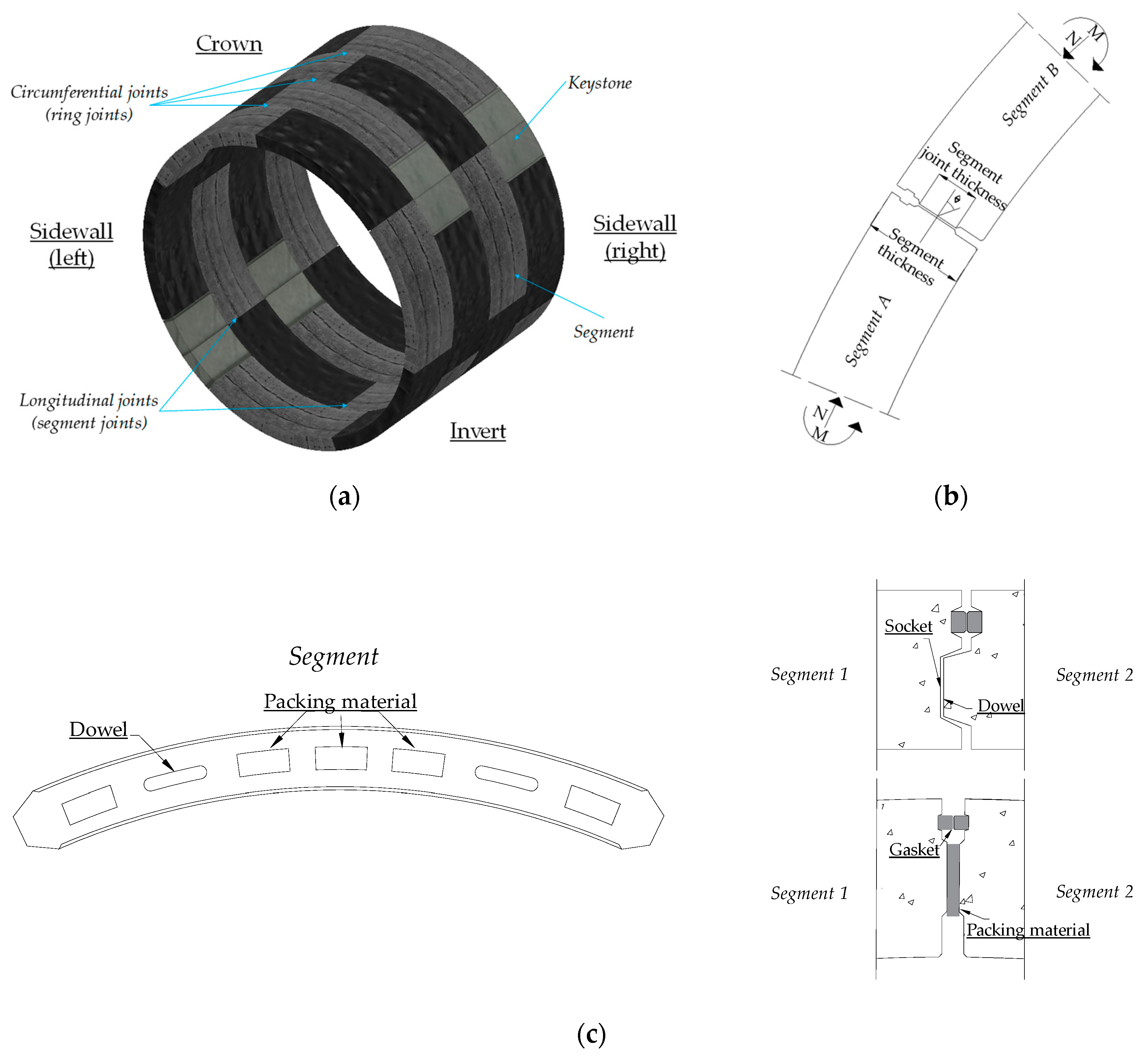
7]; with the technique, it is possible to excavate a tunnel while simultaneously placing a primary lining based on segmental rings. This lining is formed by precast segments, generally of reinforced concrete, that work as temporary or permanent supports (
Figure 1a). The TBM method is one of the most used in recent years for the construction of tunnels in soft soils [
2,
5,
8,
9,
10,
11,
12].
With this construction technique, segmental rings are formed, which present joints and existing joints between segments (longitudinal joints or segment joints) (
Figure 1b), as well as between rings (circumferential joints or ring joints) (
Figure 1c). Therefore, this structure cannot be considered to be a continuous lining. In
Figure 1, basic components of a typical segmental tunnel are depicted and details of a segment joint (
Figure 1b) and a ring joint (
Figure 1c) are indicated. The joints perform important structural functions which must be considered for the calculation of internal forces and displacements in the rings. These functions include loading transfer and moment distribution [
2,
5,
13,
14,
15,
16].
The importance of the longitudinal joints has been analytically studied by several authors [
2,
13,
14,
15,
17,
18,
19] who have obtained their mechanical behavior (moment–rotation constitutive equations). Other authors have conducted experimental research into these structural elements [
2,
20,
21,
22,
23,
24,
25,
26]. Some conclusions of these studies are as follows:
- (a)
The number of longitudinal joints and their position relative to the loads are important factors in the stress level that acts in the ring.
- (b)
The flexural moment and the acting forces in the segments decrease as the number of longitudinal joints in a ring increases.
- (c)
The rotational stiffness of the longitudinal joint depends on the loads acting on it.
- (d)
The mechanical behavior of the longitudinal joints depends not only on their geometry and material but also on the type of connection used and the applied loads in the ring.
It should be noted that the axial load
N (
Figure 1b) present at the joint, created by the radial pressure imposed by the soil in the tunnel, is not constant throughout the analysis because the load depends on the global stiffness of the lining, making it necessary to perform a series of iterations during the analysis to determine the structural response of the tunnel [
2,
24]. However, these iterations are not necessary when using moment–rotation equations as they consider that the axial load
N is variable throughout the analysis [
2]. The constitutive equation used in this study was validated by Peña et al. [
2] wherein experimental scaled-down models of typical segment joints were tested considering a variable axial load with a constant eccentricity to avoid the iterations during the loading process. In addition, Peña et al. [
24] carried out two types of analysis in single rings considering that the axial load at the joint remained constant and variable, respectively, and were able to observe the importance of using equations which consider the variability of this force.
Experimental research into circumferential joints has been carried out by some authors. These investigations were presented in the work by Pialarissi [
27], where different friction coefficients were recommended depending on the packing material situated on the joint. The load-deformation behavior of this type of joint depends on the normal stress acting on it.
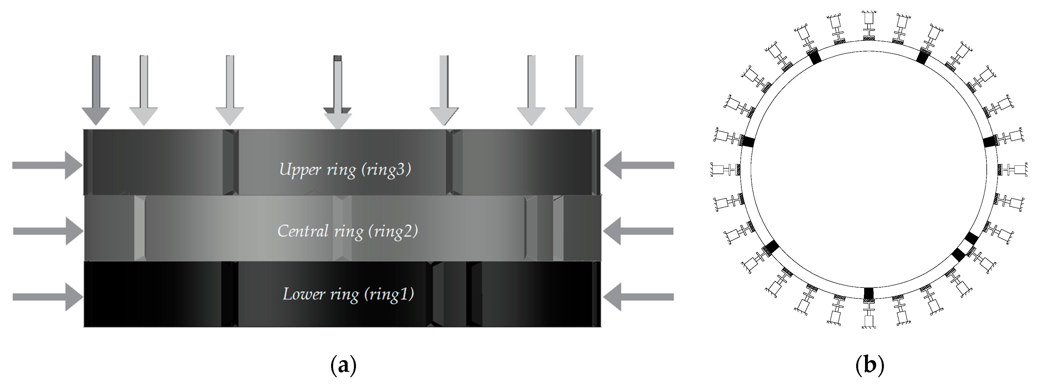
On the other hand, there are few experimental (lab-based) research works that include the effect of the coupling between rings of a tunnel created by the construction process of the TBM. In Blom and Oosterhout [
28], full-scale tests consisting of segments from the Botlek Railway Tunnel were carried out at the Stevin II Laboratory of the Delft University of Technology. The set-up contained three segmental reinforced concrete rings (lower ring or ring 1, central ring or ring 2 and upper ring or ring 3), with a width of 1.5 m, situated in a vertical position, ignoring the effect of gravity (
Figure 2a).
Each segmental ring was composed of seven reinforced concrete segments and a keystone (
Figure 2a) with a system radius of 4.525 mm and a segment thickness of 400 mm [
29]. Longitudinal joints were placed in a stretched bond alignment, resulting in segment joints in the same circumferential location in the upper and lower ring. It should be noted that the three keystones were situated differently in each ring.
In the segment joints, no packing material was used (concrete-to-concrete surface contact), while in the ring joints, plywood sheets were used as a packing material. To consider the TBM effect, which produces a coupling effect between rings, 14 jacks were located on top of the segments in the upper ring (
Figure 2a), while for representing the water and soil pressures on the segmental rings, 28 jacks per ring were situated on the experimental model (
Figure 2b).
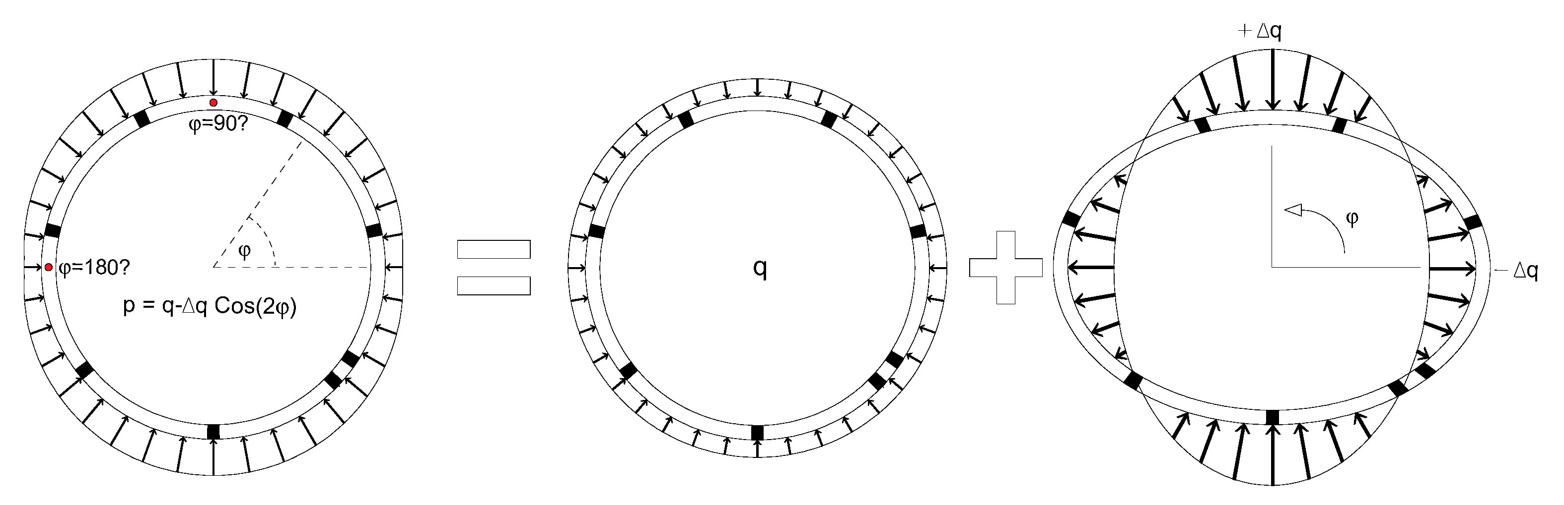
Three load steps were developed in this experimental test in order to consider the effects during the construction process of the segmental tunnel and due to the soil and water pressures originating in soft soil. In the first load step, we considered a service thrust load given by the TBM (
Figure 2a) of 1400 kN (100 kN/jack). It should be noted that, in the experimental model, four steel plates were situated allowing radial translations and restraining the tangential movements of the model, avoiding rigid body rotation. In the second load step, a uniform radial load (
Figure 3) of a 225 kN/jack was applied. Finally, in the last load step, an ovalization load was applied (
Figure 3), which was increased until the failure (Ultimate State Limit) of the rings, achieving a value of 23.5 kN/jack, according to this equation:
To represent the structural behavior of this type of structure, there are some simplified models [
2,
19] which have been used by engineers in practice to analyze and design segmental tunnels; some of these include beam elements to represent the segments and springs to simulate the nonlinearity of the joints, reducing the computational effort spent in two or three-dimensional models. In general, these simplified models do not consider the coupling effect between rings created by the construction process of the TBM method. This effect modifies the structural response in the lining, increasing its structural capacity as this coupling increases [
5].
Thus, there are few research works which include (lab-based) experimental or simplified numerical models that take into account the interaction between rings for the structural analysis of segmental tunnels. This parameter is important to determine the “real” structural load capacity of a concrete segmental lining, enhance its structural design and also reduce costs, while a “rational” structural design will be able to reduce materials—e.g., concrete volume—by optimizing transversal sections, reducing manufacturing costs and achieving more environmentally friendly designs by reducing CO
2 emissions. This sustainability philosophy has gained increased traction in the construction of segmental tunnels with the incorporation of such new technologies as geopolymers [
30,
31] in some projects (geopolymer concrete); e.g., according to Šejnoha et al. [
32], it is possible to replace a percentage of the cement used to build the concrete segments with fly ash while complying with the strength requirements of a tunnel lining.
In this paper, a simplified numerical model for the structural analysis of segmental tunnel linings considering the coupling effect (practical model) created by the TBM was carried out. This model considers the longitudinal joints as inelastic rotational springs, while the circumferential joints are considered as elastic linear springs. The segments were represented using Timoshenko beam elements. The main contribution of this study is that a feasible numerical model is proposed to determine the structural capacity of a segmental tunnel lining, considering the effect of coupled rings—an effect ignored in the most simplified structural models—achieving “rational” structural designs, optimizing resources and materials and reducing costs. However, the proposed practical model has the limitation of being applicable only when the failure mechanism of the tunnel is due to the excessive deformations given by the mechanical behavior of the joints; i.e., when a “low” longitudinal axial load in the tunnel due to the TBM is expected. The results of the proposed model are compared with those of a complex numerical model and an experimental model of a typical segmental tunnel built in soft soil. Some advantages of using this simplified model are that, firstly, a constitutive moment–rotation equation under constant eccentricity with variable axial load is used; with this, it is not necessary to iterate during the analysis [
2]. Thus, the analysis process becomes easier and faster. Second, the computational cost is reduced by using simple finite elements with their reliable constitutive equations to represent their mechanical behaviors. Third, the numerical model can be used by engineers in practice as a simple methodology which is “easy” to apply.
The outline of this paper is as follows: in
Section 2, the details of numerical models, including type of elements, constitutive models, connectivity, boundary conditions and applied forces are given for both numerical models (1D and 3D models). In
Section 3, numerical results are provided and compared to experimental results obtained from the literature and compared to a 3D complex model in order to validate the proposed model. A discussion regarding the use of this proposed practical model and its utility in structural design in comparison with complex models is depicted in
Section 4. Finally, in
Section 5, conclusions derived from this study are given.
2. Materials and Methods
As mentioned in
Section 1, the Botlek Railway Tunnel (BRT) was considered to perform the practical numerical model due to the experimental results gathered in this tunnel by using (lab-based) experimental tests according to Blom and Oosterhout [
28] and Luttikholt [
33]. These full-scale laboratory tests contributed towards a better understanding of the structural behavior and failure mechanisms of a segmental lining under an Ultimate Limit State (ULS). This tunnel was built in soft soil; according to Blom [
17], the height of the saturated soil and height of the unsaturated soil were 22.7 and 2.3 m, respectively. The specific weights of saturated and unsaturated soil were 18 × 10
−6 and 16 × 10
−6 N/mm
3, respectively. The elasticity modulus of soil was assumed to be 38.0 MPa. However, to simulate the soil and water pressures on the experimental model tested at the Stevin II Laboratory of the Delft University of Technology, including the effect of the longitudinal axial load created by its construction process, a steel frame with an external diameter of 15.7 m was designed, and this provided the reaction forces of the radial hydraulic jacks. These radial jacks (
Figure 2b) were used to simulate the water and soil pressures, installing 28 jacks per ring with a capacity of 850 kN each (84 jacks in total, applying a uniform radial load of 225 kN/jack), considering the load configuration described in
Section 1 (
Figure 3 and Equation (1)) until the failure of the experimental model (ovalization load of 23.5 kN/jack). This steel frame was designed for stiffness rather than for strength to obtain a similar experimental model and frame displacements [
29].
On the other hand, to simulate the longitudinal axial load induced by TBM, 14 jacks with a capacity of 5000 kN each were installed.
With this full-scale test, a validation of the numerical results of the proposed practical model was carried out and is presented in
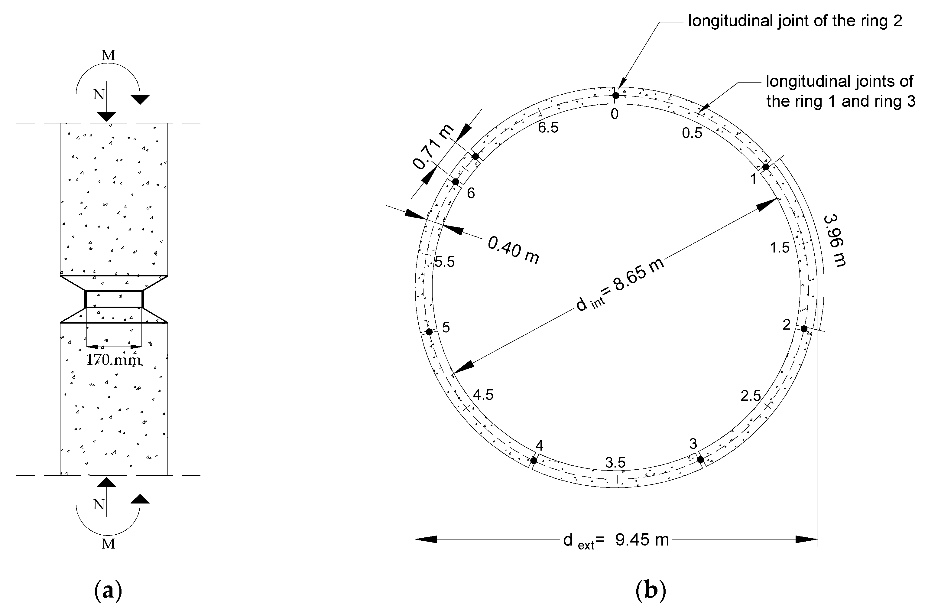
Section 3. Furthermore, a comparison with another numerical model, the 3D numerical model, was performed. In
Table 1, the geometrical properties are depicted, and in
Figure 4, the details of the locations of the segment joints of the three rings and their dimensions are depicted.
The commercial finite element package ANSYS [
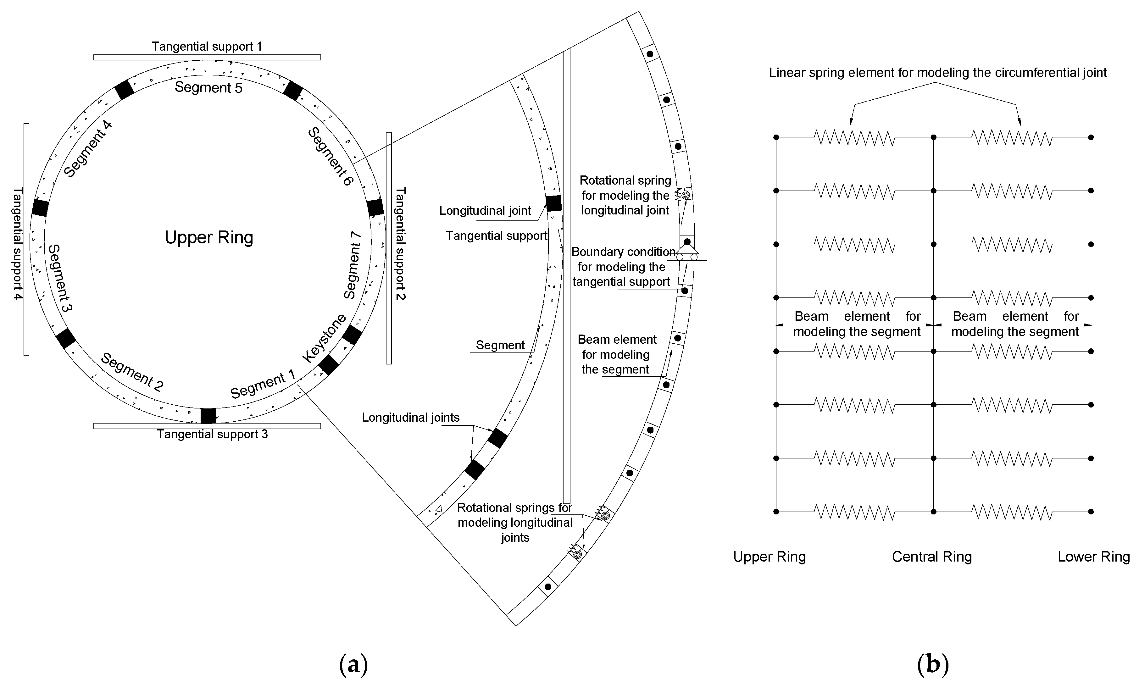
34] was used to create the proposed numerical model of a typical segmental tunnel: the study case of the BRT tunnel. This model consisted of a one-dimensional model (1D model) composed by beam elements to represent the segments with elastic–linear behavior identified as BEAM188. It should be noted that this beam element is based on Timoshenko beam theory. Consequently, the shear deformation effects were included, while the longitudinal joints were modeled by using inelastic rotational springs, identified as MPC184, by means of the moment–rotation equation proposed by Peña et al. [
2]. The circumferential joints were represented by elastic linear springs, identified as COMBIN14. In
Figure 5, the modeling strategy used to represent the experimental (lab-based) research performed by Blom and Oosterhout [
28] and by Luttikholt [
33] is depicted.
When the moment–rotation relations used to represent the mechanical behavior of segment joints consider the axial load at the joint as a constant value, it is necessary to make a series of iterations during the analysis to determine the structural response of the lining. However, the mechanical behavior of segment joints has been studied analytically [
2], taking into account the variation of the axial load in the joint. This relation was used in this study, showing that these iterations are not necessary.
For each longitudinal joint, the moment–rotation relation proposed in Peña et al. [
2] was used to represent its mechanical behavior. This constitutive behavior is presented in Equations (2)–(4).
where
M = flexural moment;
ϕ = rotation;
h = longitudinal joint thickness;
b = longitudinal joint width;
ν = Poisson’s ratio;
E = modulus of elasticity;
e = load eccentricity.
On the other hand, Equation (3) determines the initial stiffness of the longitudinal joint.
where
Mmax = maximum moment;
Pmax = theoretical maximum load;
A1 = contact area in function of eccentricity;
A2 = area of the joint;
f′c = nominal compressive strength.
The yield rotation is calculated with Equation (4).
where
The maximum moment
Mmax and the yield rotation
φy were calculated by applying Equations (3) and (4). In
Table 2, the geometrical and mechanical properties of the segment joint used in the proposed model are depicted.
The circumferential joints were modeled by means of elastic springs to detect slips between rings (
Figure 5). In these joints, the spring stiffness used was 10
7 N/mm according to Luttikholt [
33], in whose work the results of the experimental tests of the Botlek Railway Tunnel are presented.
Figure 6 shows the simplified numerical model used to represent the experimental model depicted in Blom and Oosterhout [
28] and in Luttikholt [
33]. The four tangential supports were considered to stabilize the model, as in the experimental model, and the load protocol was assigned in the simplified structural model to validate this modeling strategy.
On the other hand, in the three-dimensional model (3D model), the reinforcing bars of the segments were included by means of a smeared approach (volume ratio), and the nonlinear material model proposed by William and Warnke [
35] was used to simulate the concrete behavior of crushing in compression and cracking in tension. In addition, contact elements were used to represent the mechanical behavior of joints; with these elements, the stiffness of each joint is updated during the loading process, making the structural analysis “more precise” than in the simplified models, albeit with more computational costs. The segments were modeled by using an eight-node solid element identified as SOLID65, while the joints were considered by means of the contact elements identified as CONTA173 and TARGE170. In longitudinal joints, the contact between the surfaces was considered as perfectly rough; this corresponds to an infinite friction coefficient. Thus, only the rotation of the segment joints was considered, which matched the behavior obtained by experimental tests [
2,
12,
20,
21,
22,
24].
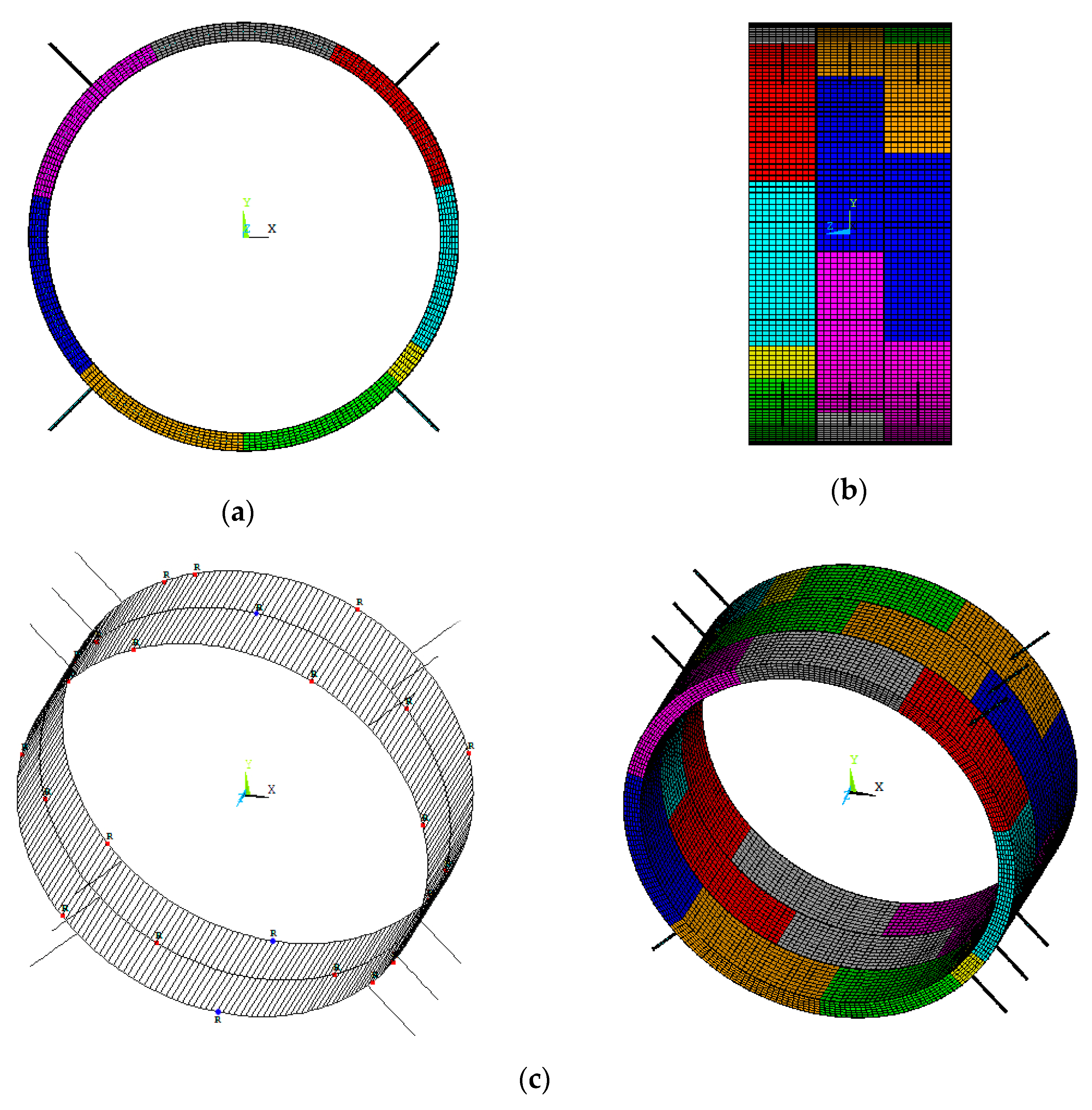
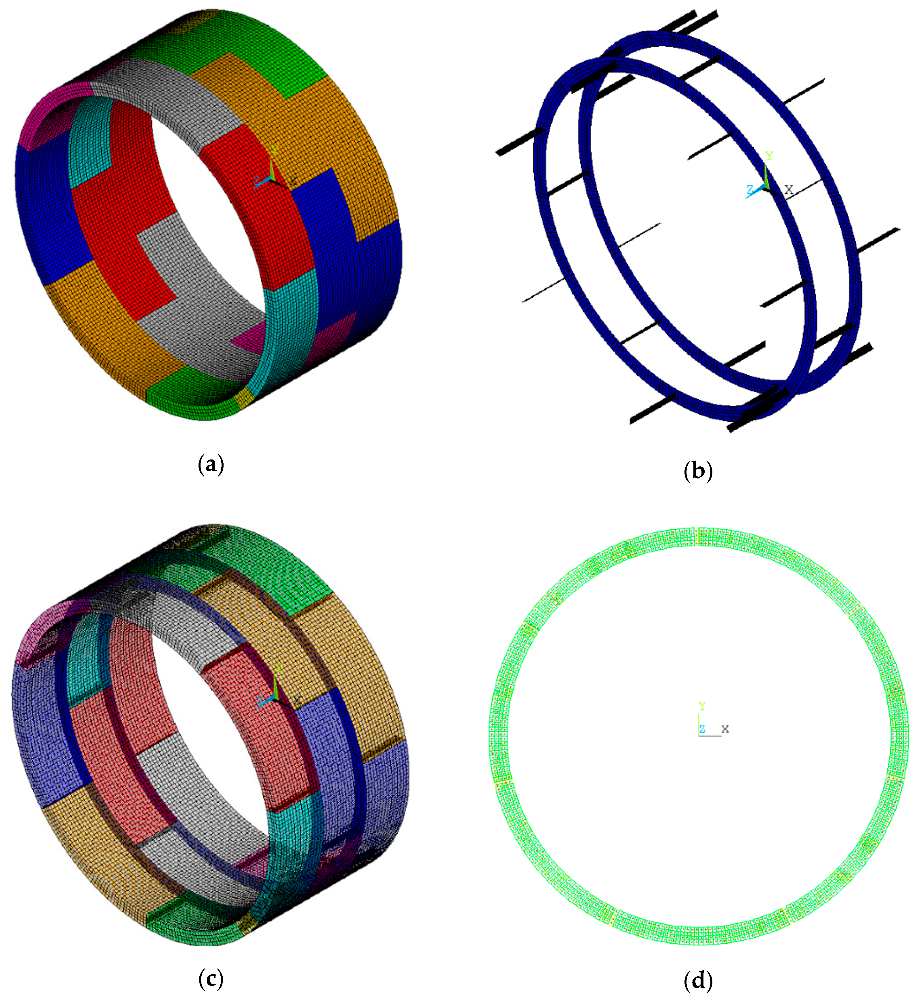
In
Figure 7, the 3D numerical model (complex model) is depicted showing the solid and contact elements and the smeared approach for reinforcing steel. The details of the 3D numerical model are presented in Galván et al. [
5].
The mechanical properties of each model for BRT, including the experimental model (Exp model), are depicted in
Table 3.
It is possible to observe that the proposed model (1D model with coupling) does not include inelastic mechanical properties in the segments.
In order to reduce the computational effort in the 3D model, the compressive damage was ignored because the main damage in the segments was caused by tensile stresses, as reported by Peña et al. [
2], Galván et al. [
5], Carpio et al. [
12] and Luttikholt [
33].
3. Results
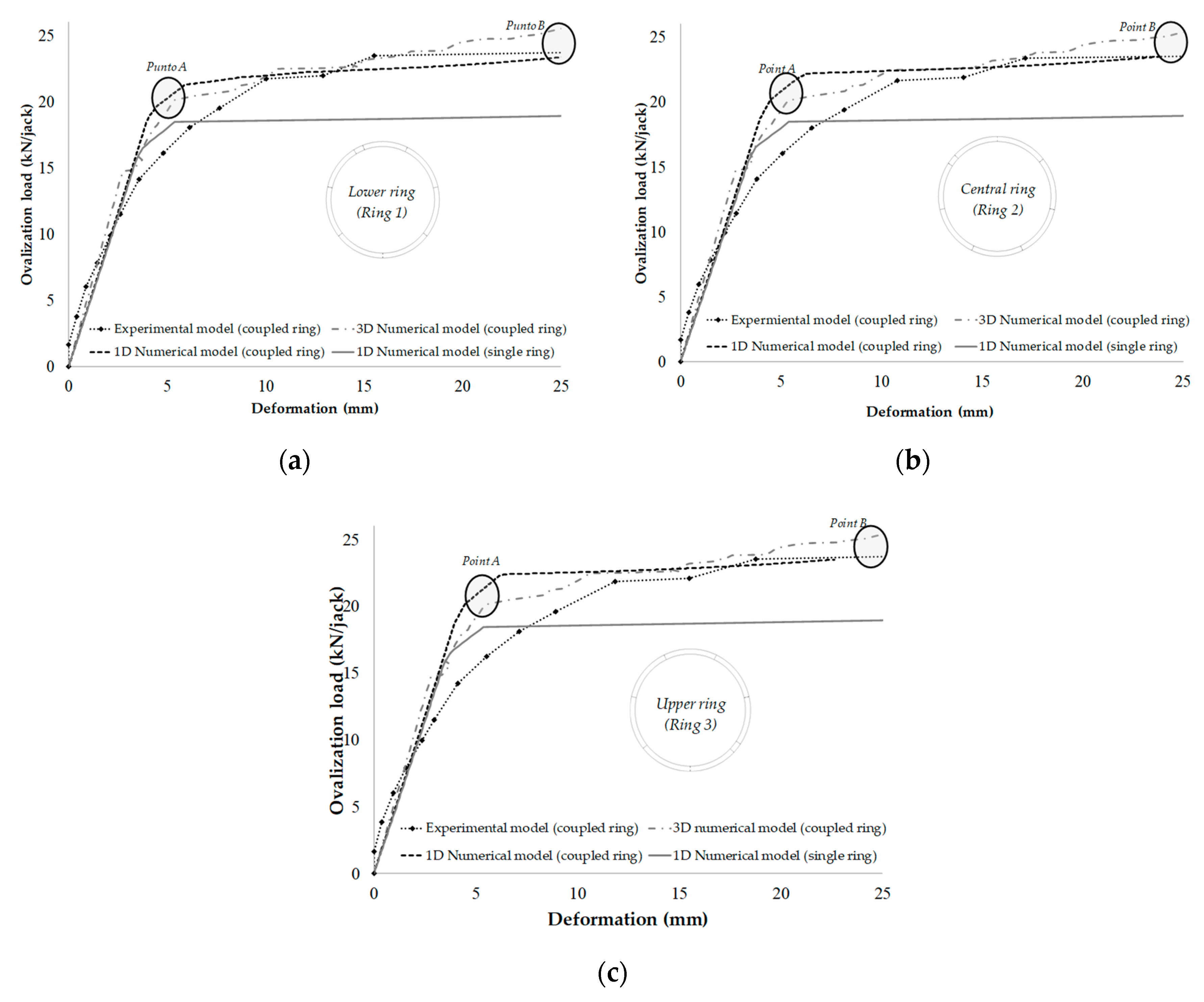
The comparison between 1D, 3D and experimental models is presented in this section. Ovalization load-deformation curves are shown in
Figure 8. For these curves, in each ring, the average deformation obtained with the four points where the maximum radial deformations were found was used. In this figure, it is possible to note that the 3D model and 1D model, when the interaction between rings is included, present a “similar” global structural response, with the 1D model obtaining approximately the same load capacity as that obtained from 3D and experimental models (approximately 95%). There are two points indicated in this figure to represent the location of the yielding load and ultimate deformation in the tunnel, called Point A and Point B, respectively.
Obviously, the global structural responses given in the 3D model and experimental model are more realistic. However, the proposed 1D model requires a short processing time (approximately 40 times smaller than the complex model), and a large degree of insight in the structural behavior is quickly gathered with a minor error of 5% of the structural capacity given by 3D and experimental models. In
Figure 8, it is possible to observe that the numerical models of single rings [
2] were included (rings without coupling). The structural load capacity of these rings was approximately 80% of the value obtained with the experimental model and the practical model proposed in this study. For this reason, it is important to include the effect of the interaction between rings (coupled rings) due to the TBM effect [
5].
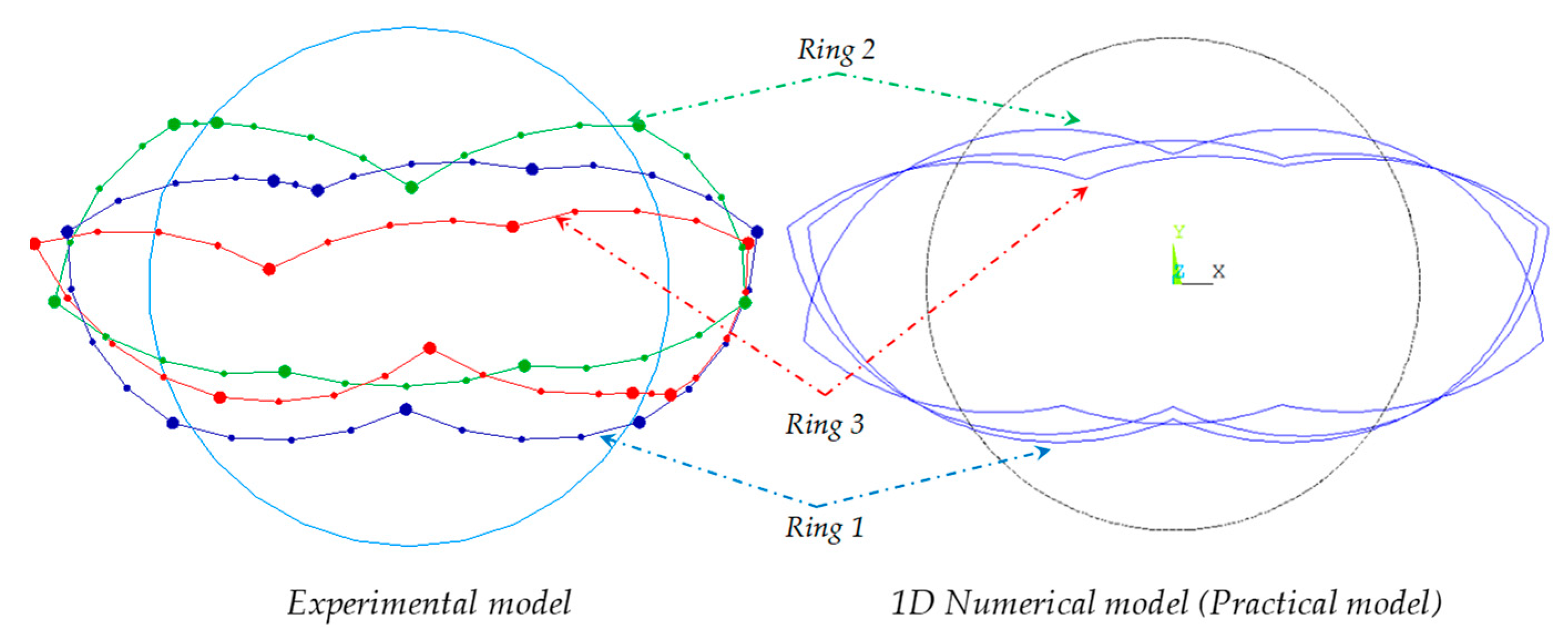
Figure 9 shows the deformed configurations of the rings obtained from the experimental and practical numerical models. These are similar in both models, corresponding to Point B (ultimate deformation of the tunnel) of the ovalization load-deformation curves. According to Luttikholt [
33], during the experiment, it was not noticed that the deformations of the upper and lower ring were different. However, in the proposed practical model, ring 1 and ring 3 were deformed almost exactly equally, which was logical due to the location of the segment joints of these two rings.
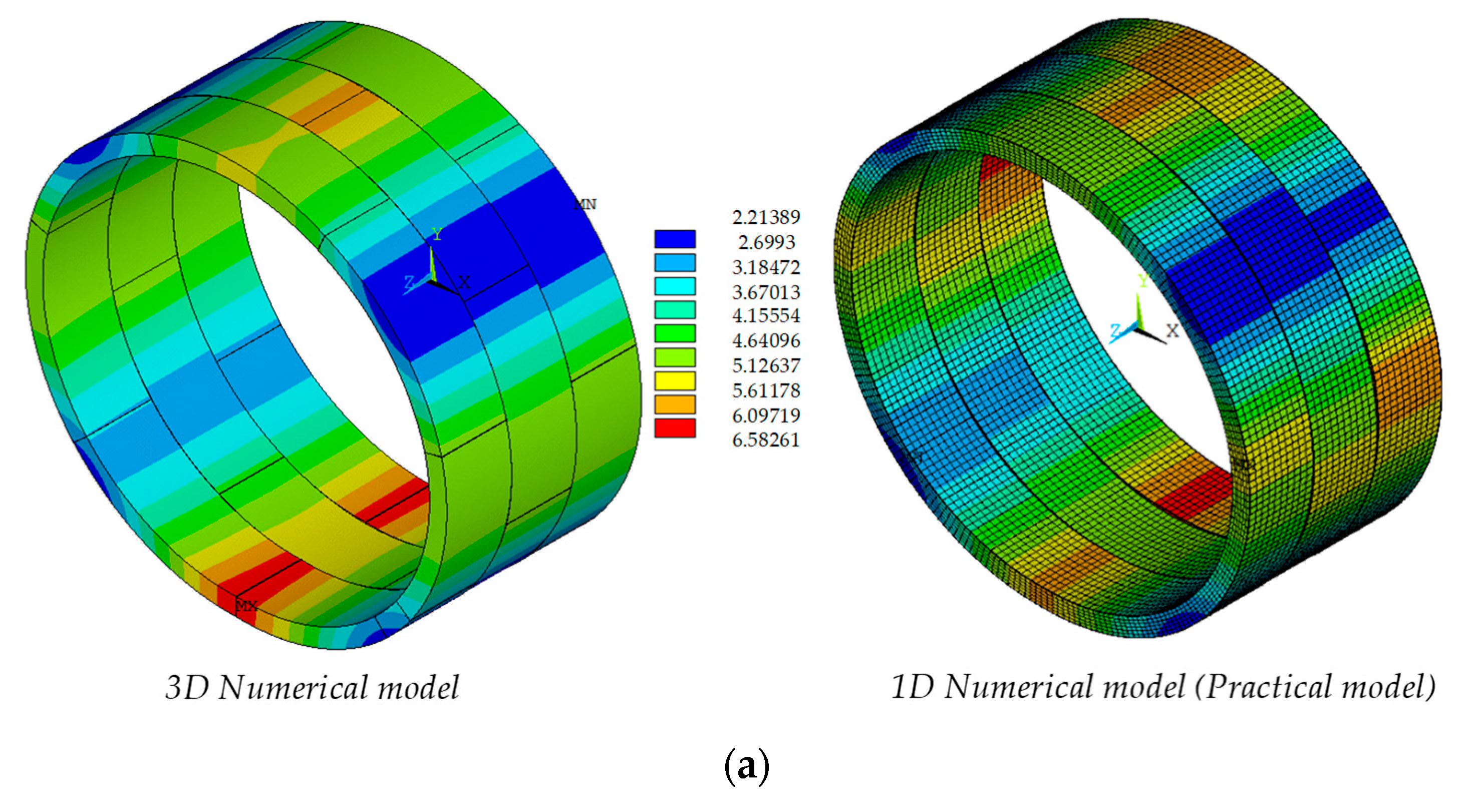
The displacements generated in each numerical model for these two points (Point A and Point B) of the ovalization load-deformation curves are depicted in
Figure 10. These displacements are very similar between both models. It should be noted that this is due to the longitudinal axial load given in the experiment (1400 kN) producing a “low” interaction between rings [
5,
11]. In this case, the structural response depends more on the mechanical behavior of the segment and ring joints (moment–rotation and load-deformation behavior for the segment and ring joints, respectively) than the damage in the segments [
5]. A practical numerical model that considers the behavior of the segments by means of an elastic material model and the joints using springs will produce a “good” estimation of the “real” behavior when a “low” interaction is produced due to the construction process of the TBM.
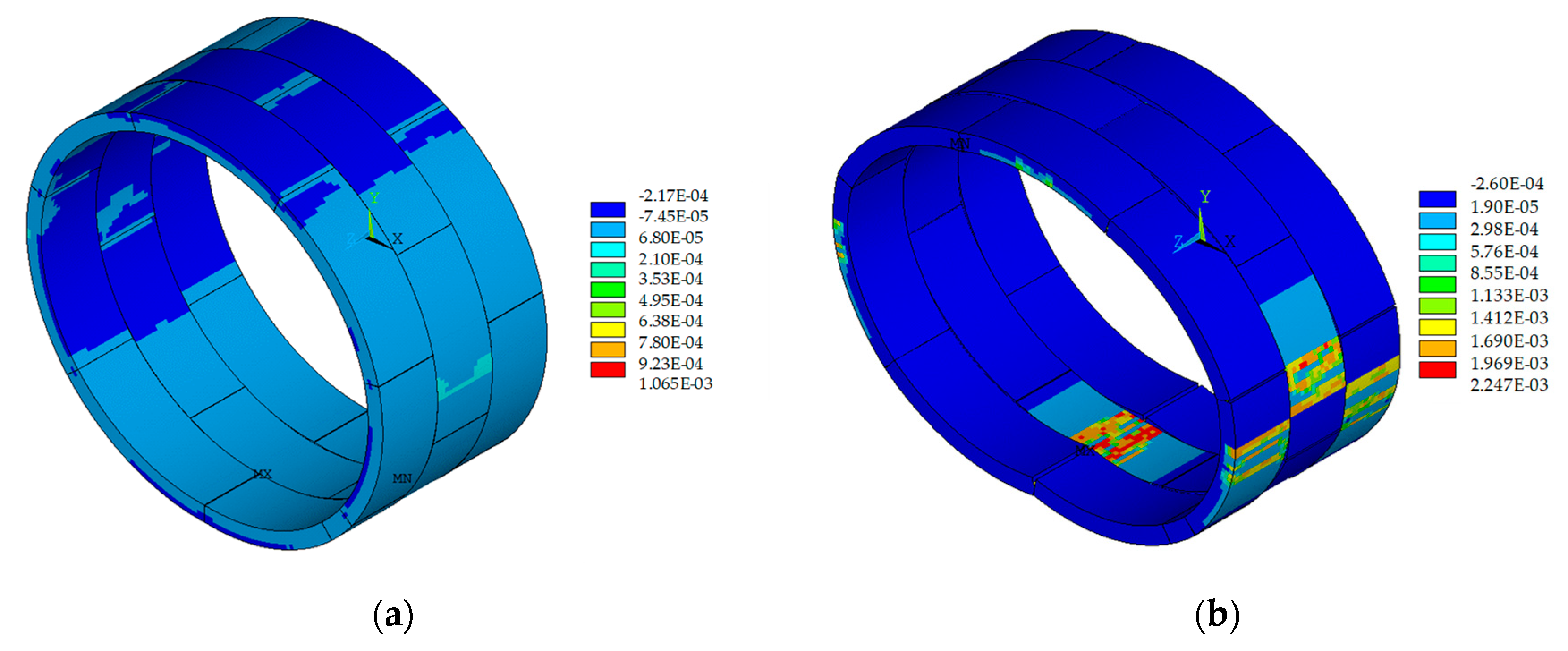
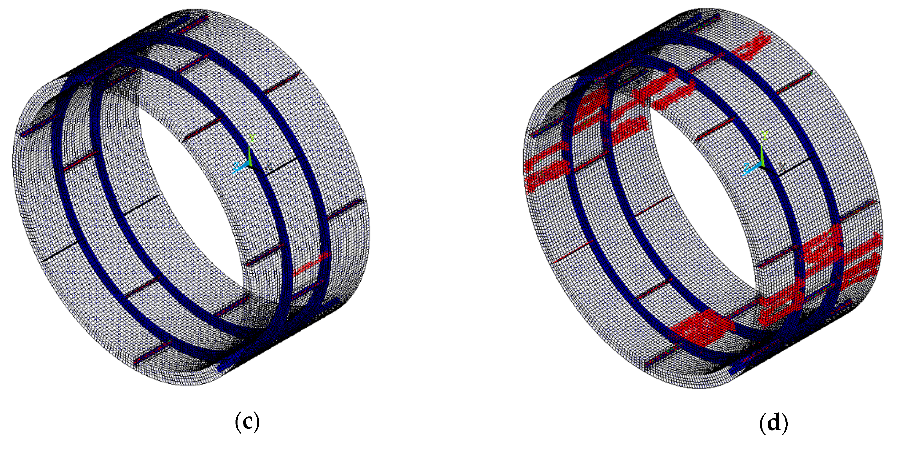
In
Figure 11, additional results given by the 3D model are presented. The reinforcing bars of the flexural steel do not yield in Point A. After this point, the segment joints begin to open. In Point B, the reinforcing bars of ring 2 yield in the invert zone, because no joint is present in this location. However, in the other two rings, in the same zone, a yielding of the rebars does not occur due to the location of longitudinal joints. On the other hand, the damage of the reinforced concrete segments in Point A does not occur or is minor. This explains that the failure mechanism is due to the aperture of the segment joints; for this reason, the proposed practical model represents the structural behavior of 3D and experimental models, and because of this, the behavior is governed by the mechanical behavior of the joints. In these cases, this simplified numerical model is good enough to analyze and design this type of structure.
4. Discussion
Non-linear analyses must be carried out when designing a segmental tunnel due to the presence of joints, as the flexibility of the joints modifies the structural response of the lining. Structural designers need simple and reliable modeling methodology to analyze and design this type of construction project. There are many 3D models which include different types of nonlinearities in their elements and materials based on Finite Element Method (FEM) to analyze them; these are complex and incur a significant computational cost. In this paper, a practical model based on FEM composed of beam and spring elements is proposed in order to help engineers in practice to perform a “realistic” structural analysis and design segmental tunnel linings using a simplified numerical model (1D model), reducing the computational effort (in the case study, a reduction of 40 times). The difference of this model with other 1D models is the incorporation of circumferential joints to include the interaction between rings—a parameter generally ignored in simplified numerical models. If this parameter is not included, the structural load capacity of a segmental tunnel lining is underestimated, as was possible to observe by considering the stiffness of the axial springs of the circumferential joints with a value of zero, simulating that the rings work in an independent way (as single rings). In this case, the simplified models with single rings underestimated the structural load capacity, obtaining approximately 80% of the values obtained from the experimental and 3D models presented in this study. However, if the simplified models consider the interaction between rings (an interaction included in the proposed practical model), the ultimate loading capacity obtained was approximately 95% of the values obtained from the experimental and 3D models, practically the same structural capacity.
The proposed model presented some differences compared to experimental and 3D models. The first stiffness changes produced in the experimental and 3D models observed in the ovalization load-deformation curves occurred due to the joint apertures and the microcracking given in the segments, while in the proposed model, these changes were only shown for the mechanical behavior of joints due to the elastic behavior of the segments. However, from the engineering point of view, the global structural behavior is very similar in the three models (1D, 3D and experimental models).
The deformed configuration and displacements given in the proposed model and 3D model were practically the same. These results were obtained at two points (the yielding load of the lining denoted as Point A, and the ultimate deformation of the tunnel, called Point B) of the ovalization load-deformation curve. In Point A, it was possible to observe from the numerical results of the 3D model that the damage in the segments is minor. Therefore, the structural behavior depends on the mechanical behavior of the joints. For this reason, the displacements of the proposed model were practically the same displacements as those in the 3D model. On the other hand, for Point B, the failure was shown in both models given by the joint apertures, including for the 3D model the damage in the segments. The configuration the displacements was very similar at this point because the collapse mechanism was governed by the mechanical behavior of the joints.
It should be noted that the collapse mechanism of a segmental tunnel depends on the interaction between rings and therefore of the longitudinal axial load due to its construction process (TBM method). Rings will fail due to excessive deformations created by joint apertures with a “low” interaction between rings. However, with a “high” interaction, the rings will work together, their deformations will be reduced, and their collapse mechanism will be caused by internal forces that will produce damage (tensile cracking) in the reinforced concrete segments. Therefore, if a practical model considers the segments with an elastic linear behavior, the computational cost will be reduced, but this consideration must only be used when the collapse mechanism is governed by the mechanical behavior of the joints (low interaction between rings).
5. Conclusions
The cracking in the 3D non-linear model of the lining is presented in the crown invert and sidewall zones. However, due to the nonlinearity of the joints, the changes of the stiffness of this structure in the case study were governed by their mechanical behavior (joint apertures) due to the “low” interaction between rings. For this reason, with the proposed practical model, it is possible determine the global structural response of the lining when a “low” longitudinal axial load is expected in the tunnel due to its construction process (TBM method).
The effect of the coupling between rings in the proposed model increases the structural load capacity of the lining, predicting the “same” capacity as that in the experimental model; for the case study, this increase was approximately 20% compared to the capacity obtained by modeling single rings. The reason for this is that the coupled rings work together to resist the loads, achieving a redistribution of internal forces in the rings, which increases the ultimate capacity of the tunnel.
It is important to determine the “real” load capacity of the lining to enhance its structural design; this is reflected in reductions in the costs of construction (dimensions of transversal sections and therefore construction material volumes) without jeopardizing structural safety. A “rational” structural design optimizes materials, and this produces a reduction of the material volume—e.g., concrete—by reducing its manufacture CO2 emissions will be reduced, achieving the further development of more environmentally friendly designs compared to a design of the lining which ignores the effect of the coupling (single rings), in which the ultimate capacity is underestimated, producing less optimal designs which can produce increments in transversal sections and in unnecessary materials.
The importance of the segment joints is possible to observe when these avoid the propagation of the cracking and the yielding of the reinforcing steel in adjacent rings; non-linear analyses are performed due to these joints.
Therefore, with the proposed numerical model, engineers in practice will be able to determine the structural load capacity of a segmental lining when a “low” interaction between rings is expected given by TBM during its construction, achieving “rational” structural designs, optimizing resources and materials and reducing costs.


