1. Introduction
The determination of glucose concentration is extremely important clinically in the diagnosis and treatment of diabetes, but also in areas such as biotechnology and food industry [
1]. Since the first enzyme electrode was reported by the pioneering work of Clark and Lyons in 1962 [
2], researchers have generated considerable interest in the development of glucose sensors, and a variety of improvements regarding the optimization of glucose sensors, the immobilization of enzymes, and the design of redox systems have been reported [
3,
4,
5]. The most well-known amperometric glucose sensors are based on the immobilization of enzymes such as glucose oxidase (GOx), which catalyzes the oxidation of glucose in the presence of oxygen to hydrogen peroxide. Another category of glucose sensors with promising results is based on the use of redox mediators [
6,
7].
Electrochemical detection of glucose using GOx exhibits a low detection limit and high sensitivity and selectivity, but due to the intrinsic nature of enzymes, such sensors have serious stability issues [
5,
8,
9]. Indeed, the activity of GOx can be easily affected by temperature, humidity, and toxic chemicals. Moreover, several disadvantages of the enzyme-modified electrodes (e.g., high cost of the enzyme, a complicated procedure required for the immobilization of the enzyme on solid electrode, and a critical operating situation) may decrease their exploitation [
5,
10,
11]. Therefore, to overcome these drawbacks, considerable attention has been paid to the development of non-enzymatic electrodes based on the direct electro-oxidation of glucose, considered to belong to the fourth generation of glucose sensors [
12]. These sensors were fabricated by incorporating nanostructured metal [
13,
14] or metal oxides [
15,
16,
17] on the electrode surface, achieved by using inert metals, metal alloy, or metal dispersed in carbon nanotubes (CNTs), in which the inert metal or metal alloy are mixed with CNTs to form nanocomposites [
13,
18,
19,
20,
21]. Among these, copper-based materials and nanomaterials have been attracting attention for glucose detection due to the Cu
+/Cu
2+ and Cu
2+/Cu
3+ redox pair system, considered to act as an electrocatalyst in glucose detection [
14,
15,
16,
17,
22,
23,
24]. However, the morphostructural, electroactive surface area and electrochemical properties of the copper-based electrodes determine their performance in glucose electrooxidation and detection [
23].
The aim of this study is to synthesize a multiwall carbon nanotube (MWCNT)-based composite with a good stability and long lifetime for the non-enzymatic detection of glucose in aqueous solutions. The utilization of nanotubes in epoxy resin composites allowed for enhanced mechanical properties and an electrical conductivity suitable for electrochemical sensor development [
25]. Nanostructured copper benzene tricarboxylate (CuBTC), which was one of the first reported metal–organic frameworks (MOFs) in 1999 and was named HKUST1, was selected to modify the MWCNT-based composite electrode for two main reasons: the multiple application potential of this material, especially in sensing [
24], and the presence of copper in its structure which, as mentioned before, is well known as a good electrocatalyst for glucose oxidation.
In the present work, the electrochemical methodologies for the direct determination of glucose using a MWCNT-CuBTC composite electrode by cyclic voltammetry (CV), differential pulsed voltammetry (DPV), linear sweep voltammetry (LSV), chronoamperometry (CA), and multiple pulse amperometry (MPA) are described.
2. Materials and Methods
2.1. Materials
Multiwall carbon nanotubes (MWCNTs) characterized by 90% purity, a 1.5 μm length, an average diameter of 9.5 nm, and a surface area of around 250–300 m
2/g, were produced by the catalytic carbon vapor deposition (CCVD) method and were supplied by Nanocyl (Belgium). Araldite
®LY5052 and its corresponding hardener, Aradur
®5052, which were supplied by Huntsman Advanced Materials (Basel, Switzerland), were used as a polymeric matrix. The details for the synthesis of CuBTC (BTC = 1,3,5 benzentricarboxilate) have been already reported by our group [
25].
A standard stock solution of 0.1 M of glucose was prepared daily from analytical grade Merck reagents using double distillated water. The supporting electrolyte for the characterization and application of the electrode material in detection processes was a 0.1 M NaOH solution, and it was freshly prepared from NaOH of analytical purity (Merck) with double distillated water.
2.2. Preparation of the MWCNT-CuBTC Composite Electrode
The MWCNT-CuBTC composite electrode was obtained by an effective two-roll mill (TRM) procedure. The ratio of the MWCNT-CuBTC-epoxy in the composite electrode was chosen to reach 25% wt. content of MWCNTs, 25% wt. content of CuBTC, and 50% wt. content of the epoxy resin.
For the preparation of the nanocomposite, 25% wt. as-received MWCNTs were ultrasonically dispersed into tetrahydrofuran (THF), 99.8% (Sigma-Aldrich Corporation, St. Louis, MO, USA), using a Cole-Parmer® 750-watt ultrasonic processor for a specific period of time (10 min) to spread out the nanotubes, followed by homogenization with the liquid epoxy resin (without the hardener). The THF was subsequently removed in a vacuum at 60 °C for about 12 h. The resulting mixture was then further mixed with CuBTC particles through several instances of two-roll milling on a laboratory scale two-roll mill (Collin) at a constant temperature of 70 °C, and also at different time and shear intensities. These conditions allowed a simple and effective process to achieve uniform dispersion of CNTs within the epoxy. The hardener was further added, and mixing was continued for an additional 10 min to ensure an uniform homogeneity. Finally, the resulting paste was poured into polyvinyl chloride (PVC) tubes, electrical contacts were completed using copper wire, and finally the sensors were cured in an oven at 80 °C for 24 h, assuring slow cooling to room temperature within 24 h.
2.3. Morphostructural and Electrical Conductivity Characterization
The morphological characterization was performed using an XL 20 Philips scanning electron microscope (SEM) coupled with an energy dispersive X-ray (EDX) using an acceleration voltage of 15 KV.
The electrical conductivity of the MWCNT-CuBTC composite electrode was determined by four-point probe contact (DC) conductivity measurements. All measurements were performed using a DMM2000 digital multimeter and a 6221 DC current source, both provided by Keithley. A silver paste coating was used to improve the electrical contacts.
2.4. Electrochemical Experiments
Cyclic voltammetry (CV), differential pulse voltammetry (DPV), linear sweep voltammetry (LSV), chronoamperometry (CA), and multiple pulse amperometry (MPA) measurements were carried out using a computer-controlled Autolab PGSTAT 302 potentiostat/galvanostat (EcoChemie, The Netherlands).
The three-electrode system consisted of a MWCNT-CuBTC working electrode with a 0.196 cm2 geometrical area, a platinum wire as a counter electrode, and a saturated calomel reference electrode (SCE). Before each voltammogram run, the MWCNT-CuBTC composite electrode was carefully polished with abrasive paper and then by a felt-polishing pad by using 0.3 µm of alumina powder (Metrohm, Switzerland). The electrode was then sonicated for 5 min in pure water. All experiments were carried out with a typical cell of 50 mL at room temperature (25 °C). Before each detection experiment, ten repetitive cyclic voltammograms were run to achieve a stable response from the electrode.
3. Results
3.1. SEM Images
The morphological analysis was very important for the evaluation of the dispersion state, morphology, and structure of the carbon nanotubes in the epoxy matrix.
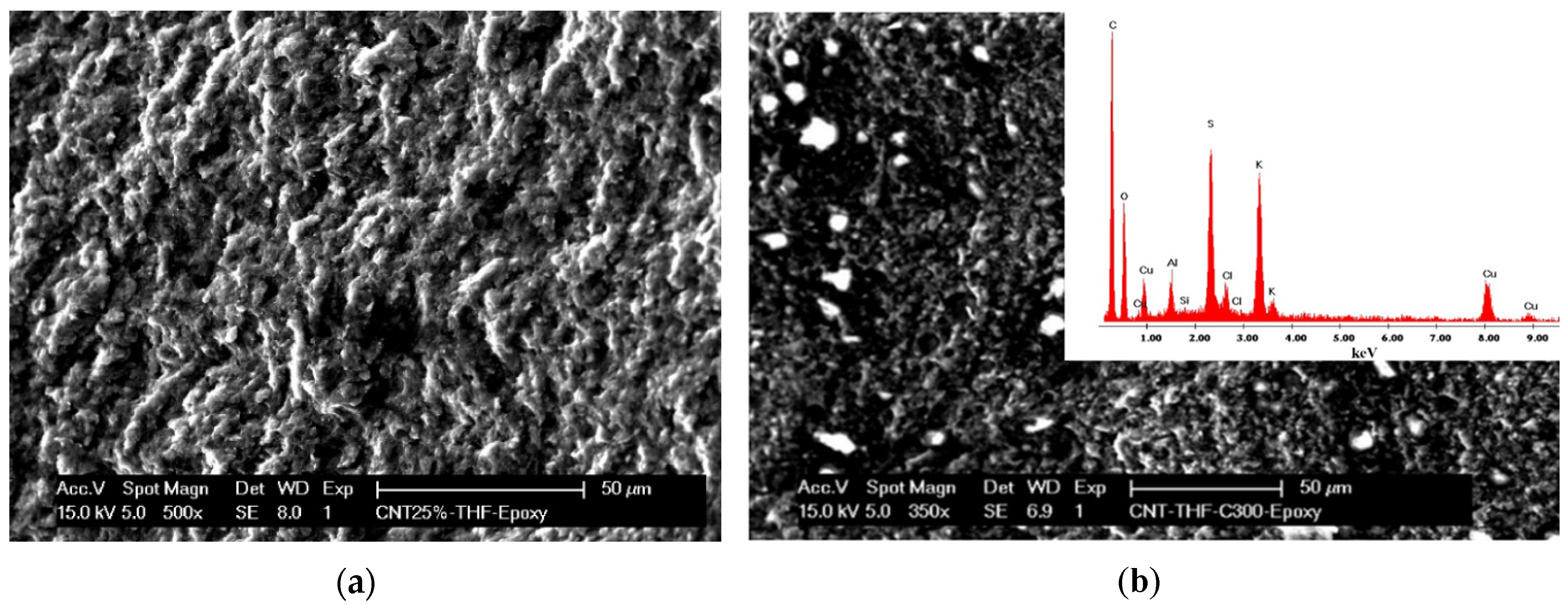
Figure 1 presents a typical SEM image of the MWCNT-CuBTC composite, showing the overall distribution of the nanotubes and CuBTC particles within the epoxy matrix. Loading of the CuBTC particles on the MWCNTs should provide a larger surface area for the electrocatalytic reaction.
3.2. Electrical and Electrochemical Characterization of the MWCNT-CuBTC Composite Electrode
The results, obtained by four-point probe (FPP) resistance measurements, for the electrical characterization of the MWCNT-CuBTC composite, in comparison with a simple MWCNT composite within an epoxy matrix, are presented in
Table 1.
It is obvious that CuBTC incorporation within the composite composition improved the electrical conductivity, which should have a positive influence on the electrochemical behavior of the composite electrode.
The ability to obtain electrochemical information from voltammetry measurements requires precise knowledge of the oxidation-reduction current peak positions for the targeted compounds and the electroactive surface area [
26,
27,
28,
29]. It is well known that potassium ferricyanide (K
3[Fe(CN)
6]) is used in the classical method for determining the electroactive area. This method assumes the recording of a cyclic voltammetry (CV) of 4 mM K
3[Fe(CN)
6] in 1 M KNO
3, supporting the electrolyte at the MWCNT-CuBTC composite electrode at different scan rates (the results are shown in the
Supplementary File). This is in accordance with the Randles–Sevcik equation:
where
A represents the area of the electrode (cm
2),
n is the number of electrons participating in the reaction (and is equal to 1),
D is the diffusion coefficient of the molecule in the solution,
C is the concentration of the probe molecule in the solution (and is 4 mM), and
v is the scan rate (Vs
−1). For each scan rate, the apparent diffusion coefficient of K
3[Fe(CN)
6] was determined, and an overall apparent diffusion coefficient of 3.21 × 10
−4 cm
2s
−1 was considered for determining the electroactive surface area, by comparison with the theoretical diffusion coefficient value of 6.7 × 10
−6 cm
2s
−1 found in the literature data [
30]. The value of 1.357 cm
2 was determined for the electroactive surface area versus the electrode geometric area of 0.196 cm
2.
3.3. Cyclic Voltammetry Measurements (CV)
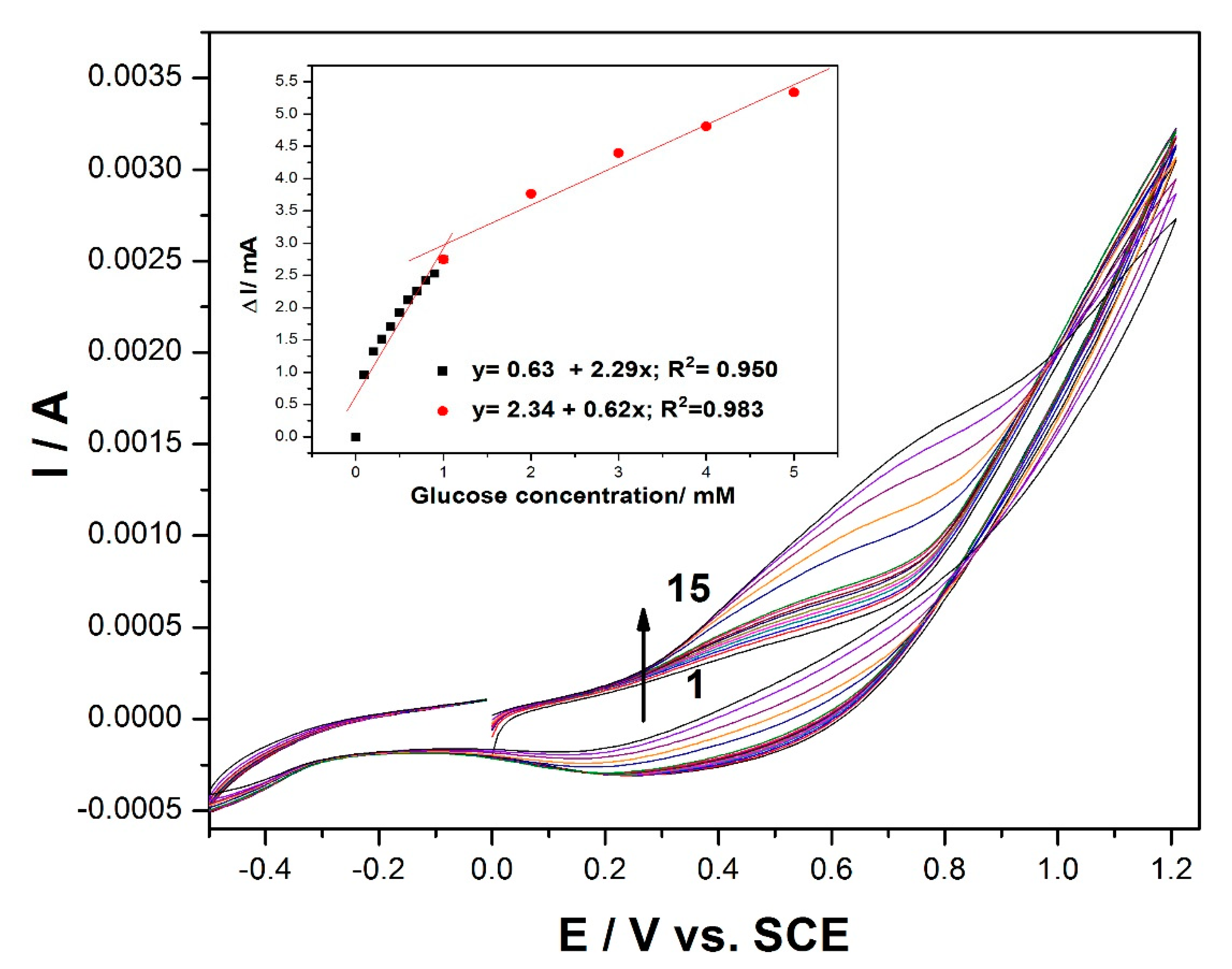
Cyclic voltammogram (CV) recordings of the MWCNT-CuBTC composite electrode in 0.1 M of an NaOH supporting electrolyte and various concentrations of glucose are shown in
Figure 2. In the absence of glucose, the MWCNT-CuBTC composite electrode exhibited a large capacitive current, and no clear oxidation peaks characteristic of copper oxidation were evidenced, probably due to the large background that overlaid the peaks. In addition, no reduction peaks corresponding to Cu(II) or Cu(I) species were observed. However, in the presence of glucose, the shape of the voltammogram was changed. The oxidation process of the glucose on the MWCNT-CuBTC composite electrode started at the potential value of +0.2 V/SCE, which should assume the involvement of Cu(I) and Cu(II) species in accordance with literature data [
31,
32]. The current corresponding to the oxidation potential value of +0.6 V/SCE increased linearly with the glucose concentration, exhibiting two slopes characteristic to two glucose concentrations, one ranging from 0.1 to 1 mM and the other from 1 to 5 mM of glucose with good correlation coefficients (inset of
Figure 2). The glucose concentration increase led to the shift of the anodic current peak to a more positive potential value, and the signal was diminished, probably due to a possible electrode surface fouling at higher glucose concentrations.
3.4. Linear Sweep Voltammetry (LSV)
Based on the presented results, the electrochemical performance of the MWCNT-CuBTC composite electrode’s ability to detect glucose was assessed by linear sweep voltammetry (LSV).
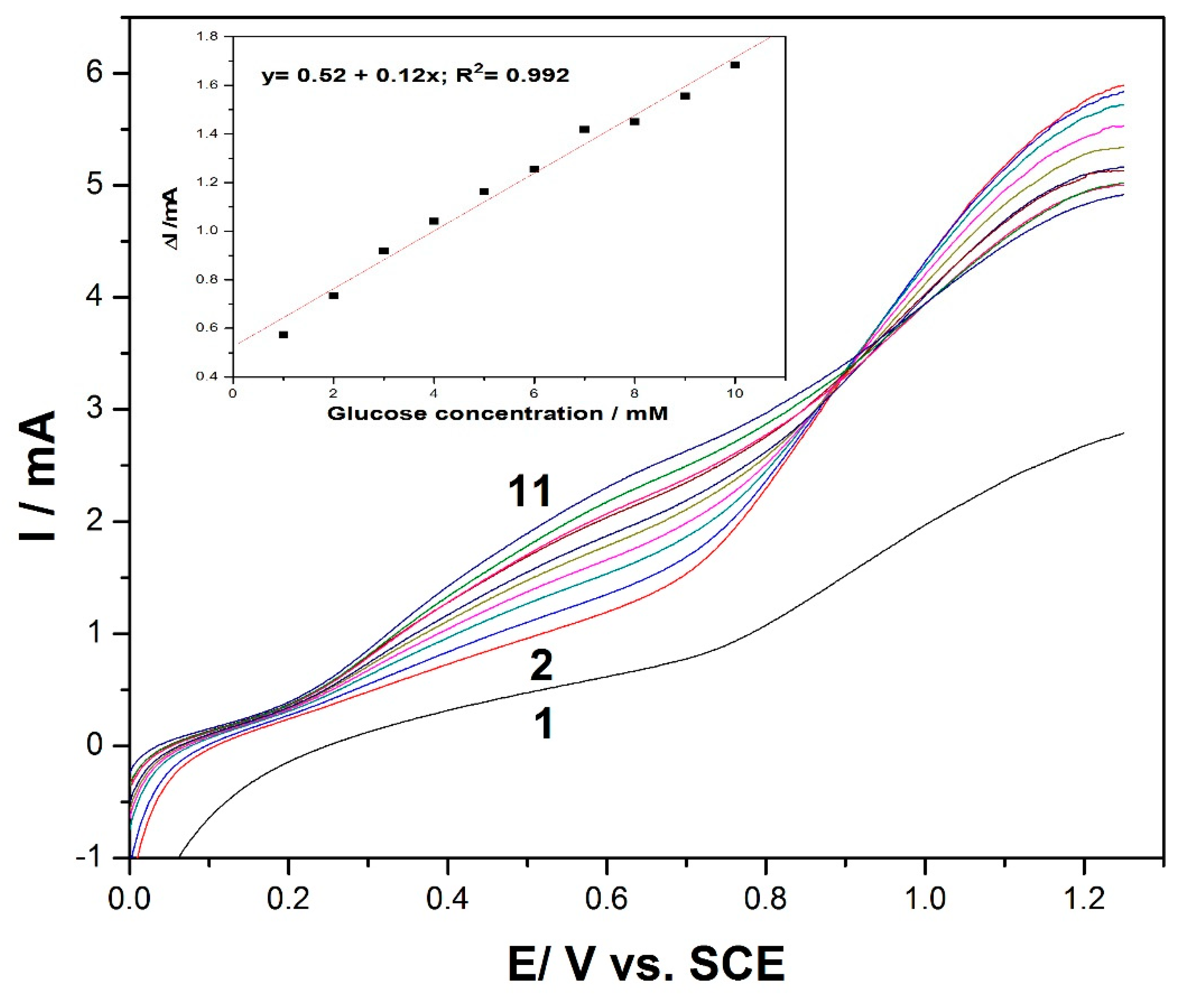
Figure 3 shows a series of LSVs recorded at the MWCNT-CuBTC composite electrode within a glucose concentration range similar to that of the CV runs. In addition, the linear dependence of the anodic current recorded at +0.6 V/SCE versus the glucose concentration was achieved with a lower sensitivity of 0.12 (inset of
Figure 3) versus the 0.62 mA·mM
−1 achieved by CV within a similar glucose concentration range, which means that the electrode fouling was stronger in its manifestation using LSV. It can also be noticed that a high response was recorded at 1 mM of glucose, with the possibility to obtain a response for lower glucose concentrations, particularly in a range below 1 mM.
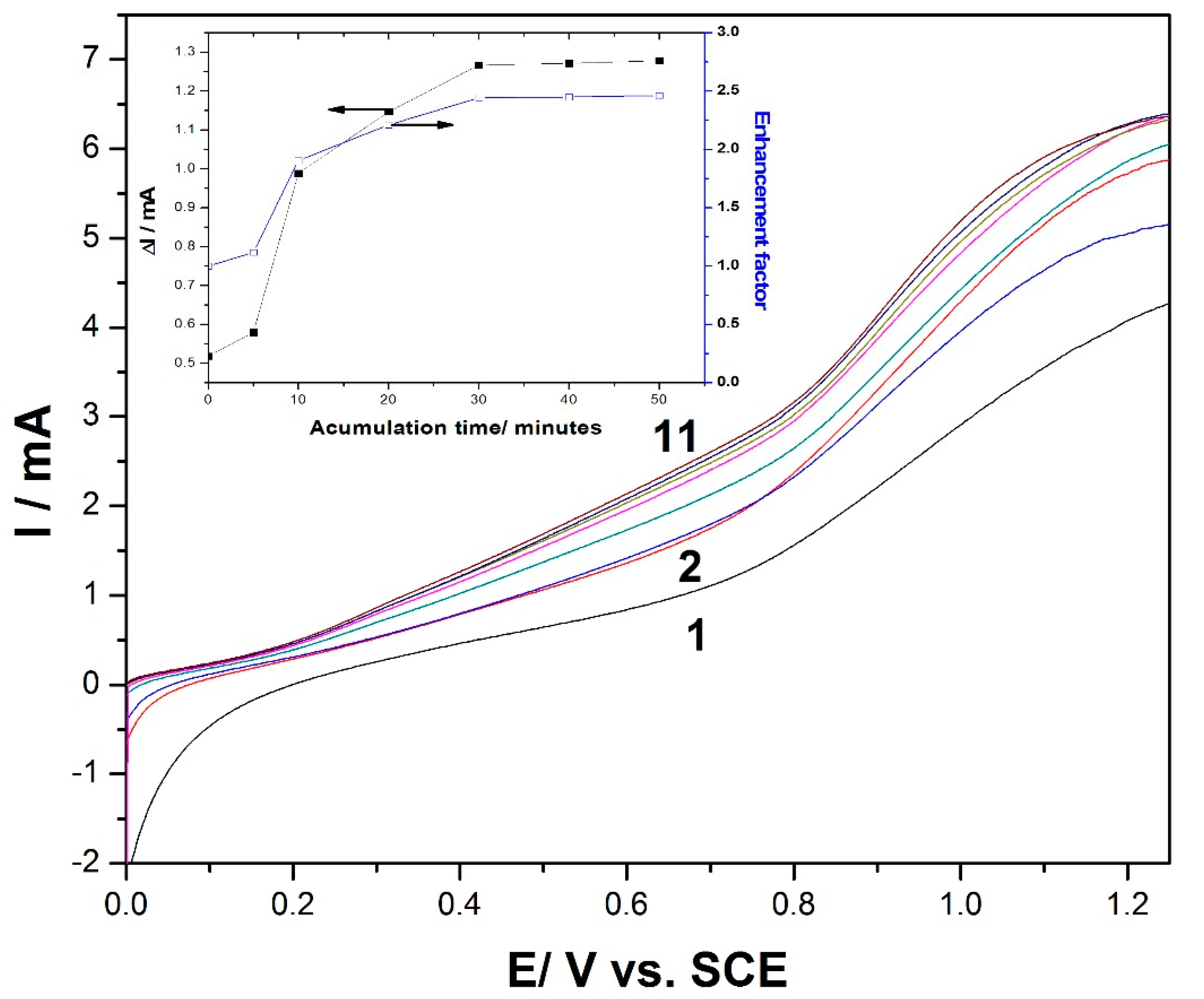
To propose a preconcentration/voltammetric detection scheme for glucose determination at the MWCNT-CuBTC composite electrode, the accumulation time represented an important parameter because it could influence the degree of adsorption on the electrode surface. An important role that may be played by MOFs is their ability to concentrate species within their nanoporous structures. To determine the enhancement factor as the ratio of the peak current before and after the sorption process, the effect of the accumulation time on the anodic peak current was investigated using LSV.
Figure 4 shows the LSV recordings at the MWCNT-CuBTC composite electrode after different accumulation times, which represent the time for maintaining the electrode at its open-circuit potential (OCP) to concentrate glucose at the electrode surface. The useful oxidation peak current and the enhancement factor, determined for 1 mM of glucose using a preconcentration/voltammetric detection procedure at different accumulation times, are shown in the inset of
Figure 4. The oxidation peak currents for this compound increased with the accumulation time up to 30 min, which was selected as the optimum accumulation time due to a maximum enhancement factor of 2.5 being reached. Meanwhile, at longer accumulation times, the peak currents remained constant, and a plateau was reached. The enhancement factor of about 2.5 at the oxidation potential of +0.6 V/SCE revealed an effective concentration effect of the MWCNT-CuBTC composite electrode on glucose, regarding the improvement of its oxidation signal. As a consequence, the accumulation time of 30 min was chosen as an optimum time for further preconcentration and linear sweep voltammetric detection experiments.
An LSV series was recorded under the optimum conditions of the preconcentration scheme, which assumed an accumulation time of 30 min within a glucose concentration ranging from 0.2 mM to 1 mM (the results are not shown here). Under these working conditions, a significant enhancement of the electroanalytical parameters of glucose detection was achieved, with a sensitivity which was about five times better and a detection limit that was five times lower (see
Table 2).
3.5. Differential Pulse Voltammetry (DPV) Measurements
Differential pulse voltammetry (DPV) was employed as a technique for the evaluation of the performance of the MWCNT-CuBTC composite electrode for glucose determination. Various operating conditions in relation to the modulation amplitudes (MAs) and the step potentials (SPs) were tested, and the best results were gathered for an MA of 0.002 V and an SP of 0.01 V.
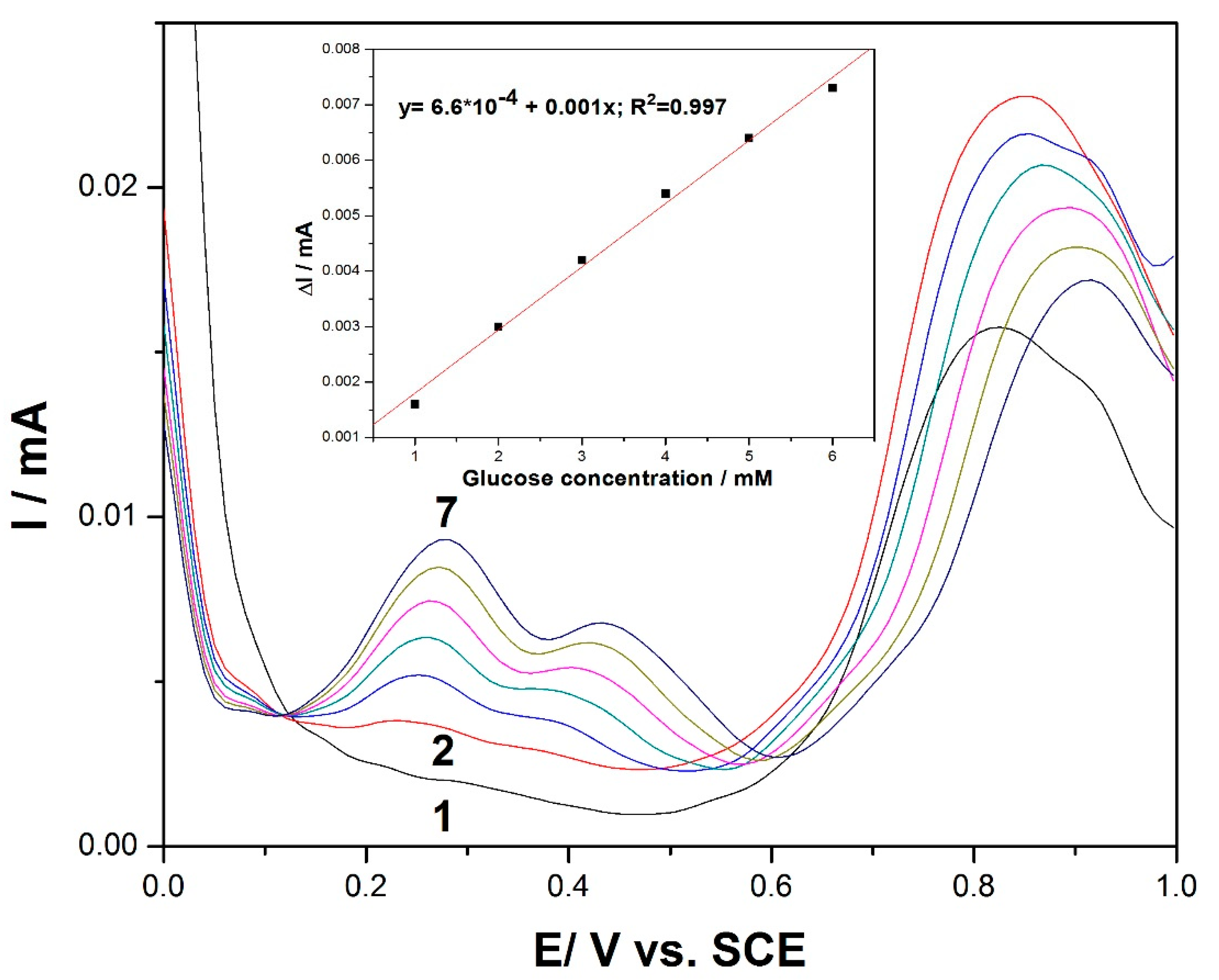
Figure 5 shows the DPV recordings for the glucose concentration ranging between 1 and 6 mM and in the potential range of +0.1 V to +0.6 V versus the SCE. The shape of the differential pulse voltammogram was very different in comparison with the CV and LSV results at the potential values of +0.27 V/SCE and +0.44 V/SCE. Two very clear oxidation peaks appeared, with their heights increasing progressively with the glucose concentration. Since the lowest potential in the electroanalysis was desired for analyte detection, the potential value of +0.27 V/SCE was selected for the calibration. Additionally, this peak height was higher in comparison with the second one recorded at +0.44 V/SCE. The useful net current signals corresponding to the oxidation peak recorded at +0.27 V/SCE were linearly dependent on the glucose concentration (inset of
Figure 5).
The potential usefulness of the DPV method for the determination of glucose content in real sample solutions was verified using aqueous solutions from a physiological serum of glucose containing 25 g glucose/500 mL serum and 5 mg glucose/100 mL serum, respectively (Hemofarm, Romania). The values of 24.5 g glucose/500 mL serum and 5.05 mg/100 mL serum represented the average content, determined using the anodic DPV technique at the MWCNT-CuBTC composite electrode associated with the standard addition method, which indicates a recovery degree of 98% and 101% respectively, indicating good recovery and reproducibility of the detection results of the glucose.
3.6. Amperometry Measurements
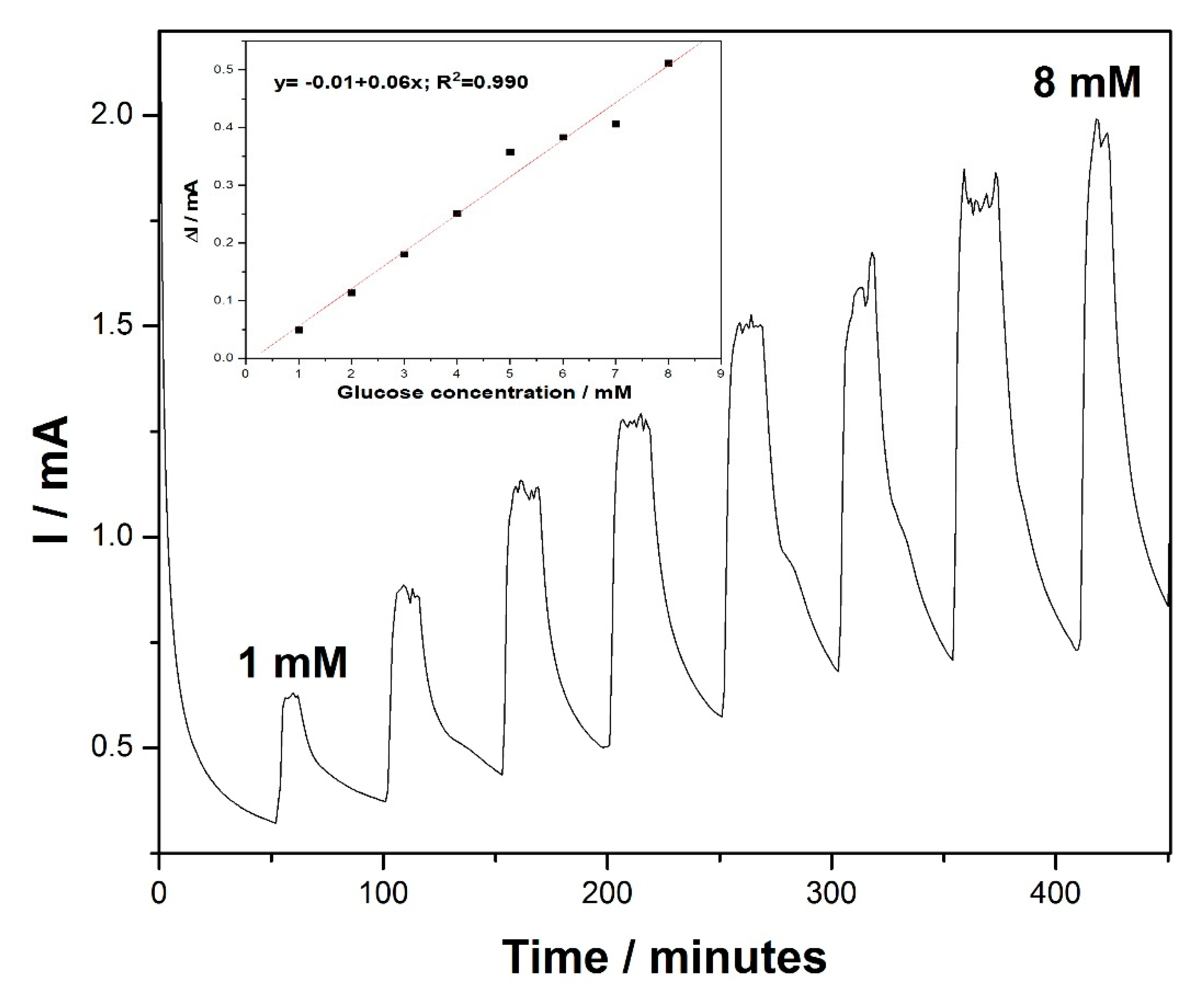
Taking into account the usefulness of the amperometry technique for practical electrodetection applications, chronoamperometry (CA) was performed for glucose detection, based on the existing, well-established essential point of reference provided by the voltammograms. The amperometric response of the MWCNT-CuBTC composite electrode, obtained for the successive and continuous addition of 1 mM of glucose in a stirring 0.1 M NaOH solution under the conditions of batch system analysis (BSA) at an applied potential of +0.6 V versus the SCE, is shown in
Figure 6. The current response of the glucose oxidation increased linearly within a concentration range from 1 mM to 8 mM (inset of
Figure 6). This technique allowed us to reach electroanalytical parameters lower than those achieved using the explored CV studies (see
Table 2) because of the electrode fouling effect.
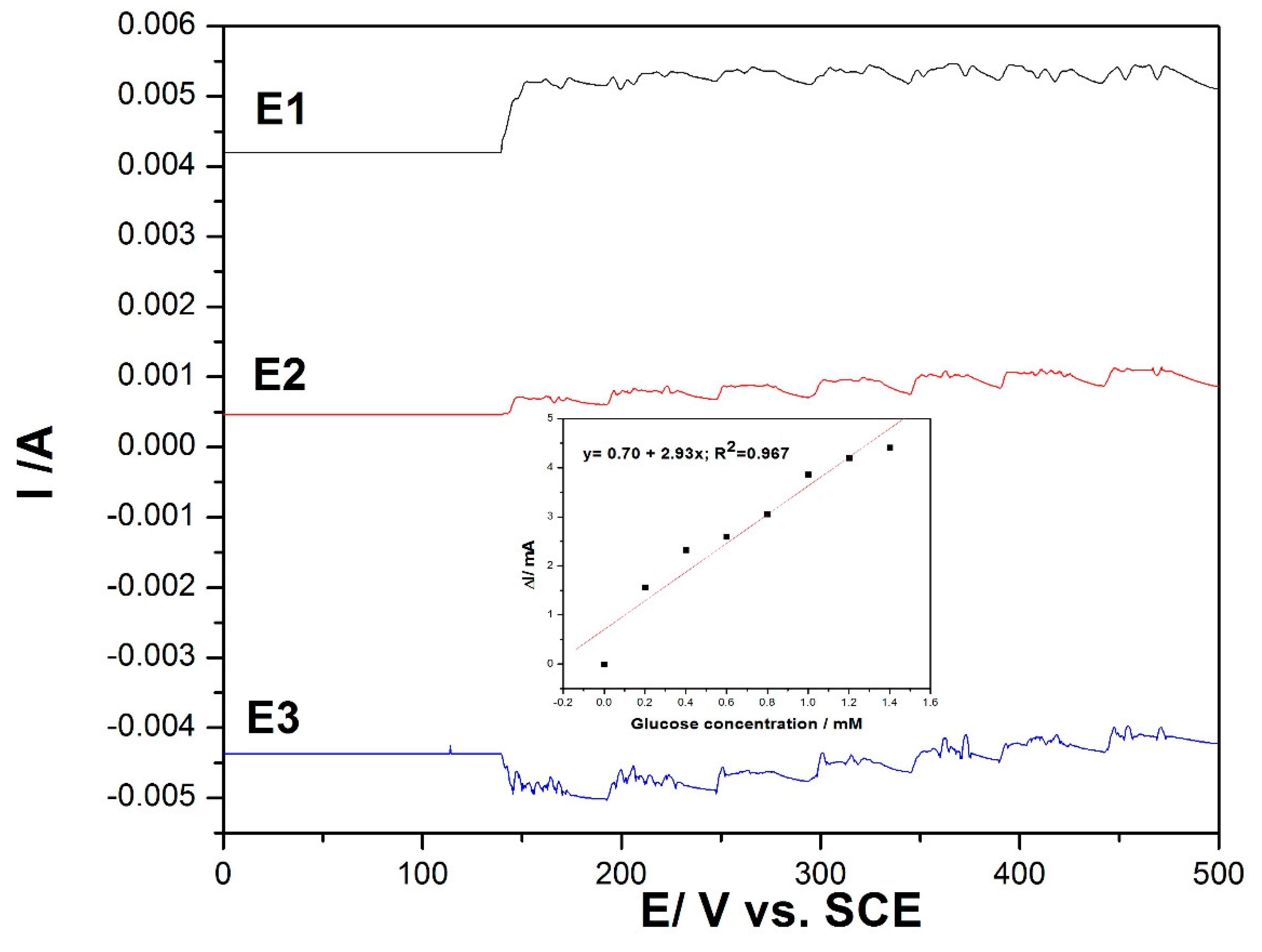
In order to avoid electrode fouling and to enhance the electroanalytical parameters for amperometric detection of the glucose, the multiple pulse amperometry (MPA) technique was applied as a variant of chronoamperometry. The MPA technique combined the anodic detection process with anodic cleaning and cathodic reactivation through alternating the pulsing potential at fixed time ranges. By this technique, in situ cleaning and reactivation of the electrode surface was assured, allowing enhancement of the electroanalytical parameters of the amperometric detection technique. Using CV as reference, MPA was applied under the following conditions:
+1.25 V/SCE for a duration of 100 ms, where the copper oxide was formed under the O2 evolution range;
+0.6 V/SCE for a duration of 50 ms, where glucose was oxidized;
−0.5 V/SCE for a duration of 100 ms for copper reduction assurance.
The results are presented in
Figure 7, and the linear dependence between the current and the glucose concentration was reached only at the potential value of +0.6 V/SCE (detection potential), while for other potential levels, no linear dependence was reached due to the specific processes occurring that allowed in situ electrode surface renewing.
The electroanalytical parameters for the non-enzymatic direct detection of glucose at the MWCNT-CuBTC composite electrode in 0.1 M of an NaOH supporting electrolyte are gathered in
Table 2.
The limit of detection (LOD) was calculated as three times the standard deviations of the intercept (S
a) divided by the slope of the regression line (b), while the limit of quantification (LQ) value was estimated as ten times the standard deviations of the intercept (S
a) divided by the slope of the regression line (b) [
33,
34].
When compared with other copper-based electrodes, the MWCNT-CuBTC composite electrode showed superiority in terms of its high sensitivity for glucose detection, as listed in
Table 3.
4. Discussion
Various types of copper-based electrode compositions (e.g., copper-copper oxide nanoparticles, nanocubes, nanowires, and MOF-derived) have been reported for the non-enzymatic determination of glucose [
15,
16,
17,
23,
24]. In general, the electrode potential (V versus the SCE) for glucose detection ranged between +0.4 and +1.0 V versus the SCE, which corresponds to the involvement of Cu
+/Cu
2+ and Cu
2+/Cu
3+ redox systems that act as electrocatalysts toward glucose oxidation. The electrocatalytic ability of glucose oxidation is responsible for the electroanalytical parameters for glucose detection. The operating variables related to the detection potential (i.e., the electrode potential at which glucose oxidation occurred) and the sensing parameters (i.e., the sensitivity and the lowest limit of detection) constitute the main highlights for the development of the glucose detection method. In comparison with other copper-based electrodes and MOF-based electrodes, the sensitivity that is given by the electron transfer is highly enhanced, which is probably directly linked to the electrode surface morphology and the electroactive centers. Moreover, very nice results for the sensitivity were achieved using MPA, which is a very useful method for practical application of glucose detection, allowing in situ renewing of the electrode surface, avoiding its fouling.
A very interesting aspect that was found in our study was related to the possibility of glucose detection at the potential value of +0.27 V/SCE that had a lower detection overvoltage in comparison with the reports presented above. A lower overvoltage oxidation potential is preferred, due to an increase in electrode ability toward a more efficient oxidation of the target analyte and more effective detection due to the better probability to avoid interferences. This desired result was achieved using DPV and was due to the combination effect of the catalytic properties of the electrode composition and the characteristics of the DPV technique. This aspect will be further studied in order to get enhanced sensitivity at this lower electrode potential value.
The interference study was achieved by using MPA techniques for ascorbic acid, uric acid, dopamine and sodium chloride, which normally coexist with glucose in human blood serum (but at concentration levels about 30 times lower than glucose), and no significant responses were found.
Moreover, the selectivity toward fructose and sucrose carbohydrates at concentrations around the ones found in real samples (10 times lower concentration than glucose) was determined. While at these concentrations, they did not interfere in the glucose response recorded by MPA, for concentrations comparable with the glucose concentration, the signal was significantly affected (about 80%). To mitigate these carbohydrate interferences, the optimization of sample pretreatment prior to electrochemical detection may be achieved. However, further studies related to permselective membrane integration within the composite composition are currently being carried out.
The operational stability of the sensor was investigated through five continuous repetitive CV runs, recorded in 1 mM of glucose and 0.1 M of NaOH, and the voltammetric response was not significantly changed. Additionally, a reproducible background current was achieved, which indicated good stability of the electrode. Electrode composition stability was checked through measurements for glucose detection after one year of storage in a common plastic bag, and a difference of about 2% was achieved, which confirms good stability of the electrode surface.
5. Conclusions
The non-enzymatic direct determination of glucose using an MWCNT-CuBTC composite electrode by cyclic voltammetry, linear sweep voltammetry, differential pulse voltammetry, chronoamperometry, and multiple pulse amperometry in an alkaline sodium hydroxide solution as a supporting electrolyte has been achieved. Very good results from calibration plots of the anodic current versus glucose concentrations resulted from all electrochemical techniques tested, and corresponding analytical data regarding the sensitivities and the relative standard deviation, the lowest limit of detection, were obtained. The adsorption properties of the MWCNT-CuBTC composite electrode for glucose were exploited for the enhancement of electroanalytical performance for glucose detection by the elaboration of the preconcentration/voltammetric detection scheme, which allowed for an improvement of five times the sensitivity and the lowest limit of detection. By comparison with other copper-based electrodes, this electrode exhibited superiority in relation to its sensitivity for glucose detection, due to its better electrocatalytic performance for glucose oxidation. The association of the differential pulse voltammetric method with the standard addition method has been successfully used for fast analytical evaluation of pharmaceutical formulations which contain glucose (serum). The average glucose content in the serum, explored as real samples, was measured with this electrode in good accordance with those indicated by the suppliers. The MWCNT-CuBTC composite electrode’s features, in relation with good electrochemical and electrocatalytic properties, good stability, reproducibility, and the long lifetime associated with the specific voltammetric and amperometric technique, make it very appropriate for real application in glucose detection and for further exploitation in the construction of new electrochemical sensors.
Author Contributions
Conceptualization, F.M. and E.I.S.; methodology, F.M. and G.G.; investigation, A.R. and S.M.; writing—original draft preparation, A.I., S.M., and A.B.; writing—review and editing, F.M., E.I.S., J.G., and G.G. All authors have read and agreed to the published version of the manuscript.
Funding
This research received no external funding.
Acknowledgments
Funding for this study was provided by a grant from the Romanian Ministry of Research and Innovation, project number PN-III-P1-1.2-PCCDI-2017-0245/26 PCCDI/2018 (SUSTENVPRO), within PNCDI III, and by a grant from the Romanian Ministry of Education and Research, CNCS—UEFISCDI, project number PD 88/2020, project code PN-III-P1-1.1-PD-2019-0676, within PNCDI III.
Conflicts of Interest
The authors declare no conflict of interest.
References
- Koschinsky, T.; Heinemann, L. Sensors for glucose monitoring: Technical and clinical aspects. Diabetes Metab. Res. Rev. 2001, 17, 113–123. [Google Scholar] [CrossRef]
- Clark, L.C., Jr.; Lyons, C. Electrode systems for continuous monitoring in cardiovascular surgery. N. Y. Ann. Acad. Sci. 1962, 102, 29–45. [Google Scholar] [CrossRef]
- Pasta, M.; La Mantia, F.; Cui, Y. Mechanism of glucose electrochemical oxidation on gold surface. Electrochim. Acta 2010, 55, 5561–5568. [Google Scholar] [CrossRef]
- Gavalas, V.G.; Law, S.A.; Ball, C.J.; Andrews, R.; Bachasa, L.G. Carbon nanotube aqueous sol-gel composites: Enzyme-friendly platforms for the development of stable biosensors. Anal. Biochem. 2004, 329, 247–252. [Google Scholar] [CrossRef] [PubMed]
- Yang, M.H.; Yang, Y.H.; Liu, Y.L.; Shen, G.L.; Yu, R.Q. Platinum nanoparticles-doped sol-gel/ carbon nanotubescomposite electrochemical sensors and biosensors. Biosens. Bioelectron. 2006, 21, 1125–1131. [Google Scholar] [CrossRef] [PubMed]
- Cherevko, S.; Chung, C.-H. The porous CuO electrode fabricated by hydrogen bubble evolution and its application to highly sensitive non-enzymatic glucose detection. Talanta 2010, 80, 1371–1377. [Google Scholar] [CrossRef] [PubMed]
- Rong, L.Q.; Yang, C.; Qian, Q.Y.; Xia, X.H. Study of the nonenzymatic glucose sensor based on highly dispersed Pt nanoparticles supported on carbon nanotubes. Talanta 2007, 72, 819–824. [Google Scholar] [CrossRef]
- Gvozdenovic, M.M.; Jugovic, B.Z.; Bezbradica, D.I.; Antov, M.G.; Knezevic-Jugovic, Z.D.; Grgur, B.N. Electrochemical determination of glucose using polyaniline electrode modified by glucose oxidase. Food Chem. 2011, 134, 396–400. [Google Scholar] [CrossRef]
- Sun, Y.P.; Buck, H.; Mallouk, T.E. Combinatorial Discovery of Alloy Electrocatalysts for Amperometric Glucose Sensors. Anal. Chem. 2001, 73, 1599–1604. [Google Scholar] [CrossRef]
- Wilson, R.; Turner, A.P.F. Glucose oxidase: An ideal enzyme. Biosens. Bioelectron. 1992, 7, 165–185. [Google Scholar] [CrossRef]
- Yang, M.; Yang, Y.; Yang, H.; Shen, G.; Yu, R. Layer-by-layer self-assembled multilayer films of carbon nanotubes and platinum nanoparticles with polyelectrolyte for the fabrication of biosensors. Biomaterials 2006, 27, 246–255. [Google Scholar] [CrossRef] [PubMed]
- Dhara, K.; Mahapatra, D.R. Electrochemical nonenzymatic sensing of glucose using advanced nanomaterials. Microchim. Acta 2017, 185, 1–32. [Google Scholar] [CrossRef] [PubMed]
- Zhu, H.; Lu, X.; Li, M.; Shao, Y.; Zhu, Z. Nonenzymatic glucose voltammetric sensor based on gold nanoparticles/carbon nanotubes/ionic liquid nanocomposite. Talanta 2009, 79, 1446–1453. [Google Scholar] [CrossRef] [PubMed]
- Nantaphol, S.; Watanabe, T.; Nomura, N.; Siangproh, W.; Chailapakul, O.; Einaga, Y. Bimetallic Pt-Au nanocatalysts electrochemically deposited on boron-doped diamond electrodes for nonenzymatic glucose detection. Biosens. Bioelectron. 2017, 98, 76–82. [Google Scholar] [CrossRef]
- Vinoth, V.; Shergilin, T.D.; Asiri, A.M.; Wu, J.J.; Anandan, S. Facile synthesisi of copper oxide microflowers for nonenzymatic glucose sensor applications. Mater. Sci. Semicond. Process. 2018, 82, 31–38. [Google Scholar] [CrossRef]
- Li, L.; Liu, Y.; Jiang, J. Synthesis of the crystalline porous copper oxide architectures derived from metal-organic framework for electrocatalytic oxidation and sensitive detection of glucose. J. Ind. Eng. Chem. 2019, 79, 330–337. [Google Scholar] [CrossRef]
- Na, W.; Lee, J.; Jun, J.; Kim, W.; Kim, Y.K.; Jang, J. Highly sensitive copper nanowire conductifve electrode for nonenzymatic glucose detection. J. Ind. Eng. Chem. 2019, 69, 358–363. [Google Scholar] [CrossRef]
- Chou, C.H.; Chen, J.C.; Tai, C.C.; Sun, I.W.; Zen, J.M. A nonenzymatic glucose sensor using nanoporous platinum electrodes prepared by electrochemical aloying/dealloying in a water-insensitive zinc chloride-1-ethyl-3 methylimidazolium chloride ionic liquid. Electroanalysis 2008, 20, 771–775. [Google Scholar] [CrossRef]
- Kurniawan, F.; Tsakova, V.; Mirsky, V.M. Gold nanoparticles in nonenzymatic electrochemical detection of sugars. Electroanalysis 2006, 18, 1937–1942. [Google Scholar] [CrossRef]
- Tominaga, M.; Nagashima, M.; Taniguchi, I. Surface poisoning during electrocatalytic monosaccharide oxidation reactions at gold electrodes in alkaline medium. Electrochem Commun. 2007, 9, 1892–1898. [Google Scholar] [CrossRef]
- Maye, M.M.; Han, L.; Kariuki, N.N.; Ly, N.K.; Chan, W.B.; Lou, J.; Zhong, C.J. Gold and Alloy nanoparticles in solution and thin film assembly: Spectrophotometric determination of molar absorptivity. Anal. Chim. Acta 2003, 496, 17–27. [Google Scholar] [CrossRef]
- Wu, C.-H.; Onno, E.; Lin, C.-Y. CuO nanoparticles decorated nano-dendrite-structured Cu Bi2O4 for highly sensitive and selective electrochemical detection of glucose. Electrochim. Acta 2017, 229, 129–140. [Google Scholar] [CrossRef]
- Radhakrishnan, S.; Kim, H.-Y.; Kim, B.-S. A novel CuS microflower superstructure based sensitive and selective nonoenzymatic glucose detection. Sens. Actuators B 2016, 233, 93–99. [Google Scholar] [CrossRef]
- Reitz, E.; Jia, W.; Gentile, M.; Wang, Y.; Lei, Y. CuO nanospheres for nonenzymatic detection of glucose. Electroanalysis 2019, 70, 330–337. [Google Scholar] [CrossRef]
- Motoc, S.; Manea, F.; Iacob, A.; Martinez-Joaristi, A.; Gascon, J.; Pop, A.; Schoonman, J. Electrochemical Selective and Simultaneous Detection of Diclofenac and Ibuprofen in Aqueous Solution Using HKUST-1 Metal-Organic Framework-Carbon Nanofiber Composite Electrode. Sensors 2016, 16, 1719. [Google Scholar] [CrossRef] [PubMed]
- Yu, J.; Shapter, J.G.; Johnston, M.R.; Quinton, J.S.; Gooding, J.J. Electron-transfer characteristics of ferrocene attached to single-walled carbon nanotubes (SWCNT) arrays directly anchored to silicon (100). Electrochim. Acta 2007, 52, 6206–6211. [Google Scholar] [CrossRef]
- Yu, J.; Shapter, J.G.; Quinton, J.S.; Johnston, M.R.; Beattie, D.A. Direct attachment of well-aligned single-walled carbon nanotube architectures to silicon (100) surfaces: A simple approach for device assembly. Phys. Chem. Chem. Phys. 2007, 9, 510–520. [Google Scholar] [CrossRef]
- Roth, K.M.; Yasseri, A.A.; Liu, Z.; Dabke, R.B.; Malinovskii, V.; Schweikart, K.-H.; Yu, L.; Tiznado, H.; Zaera, F.; Lindsey, J.S.; et al. Measurements of electron-transfer rates of charge-storage molecular monolayers on Si (100). Toward hybrid molecular/semiconductor information storage devices. J. Am. Chem. Soc. 2003, 125, 505–517. [Google Scholar] [CrossRef]
- Laviron, E. General expression of the linear potential sweep voltammogram in the case of diffusionless electrochemical systems. J. Electroanal. Chem. Interfacial Electrochem. 1979, 101, 19–28. [Google Scholar] [CrossRef]
- Konopka, S.J.; McDuffie, B. Diffusion coefficients of ferri- and ferrocyanide ions in aqueous media, using twin-electrode thin-layer electrochemistry. Anal. Chem. 1970, 42, 1741–1746. [Google Scholar] [CrossRef]
- Sun, D.; Zhu, L.; Zhu, G. Glassy carbon ceramic composite electrodes. Anal. Chim. Acta 2006, 564, 243–247. [Google Scholar] [CrossRef]
- Marioli, J.M.; Kuwana, T. Electrochemical Characterization of Carbohydrate Oxidation at Copper Electrodes. Electrochim. Acta 1992, 37, 1187–1197. [Google Scholar] [CrossRef]
- Swartz, M.E.; Krull, I.S. Analytical Method Development and Validation, 1st ed.; Marcel Dekker Inc.: New York, NY, USA, 1997. [Google Scholar]
- Jain, R.; Rather, J.A. Voltammetric behaviour of drotaverine hydrochloride in surfactant media and its enhancement determination in Tween-20. Colloids Surf. B Biointerfaces 2011, 82, 333–339. [Google Scholar] [CrossRef]
- Muthumariappan, A.; Sakthivel, K.; Chen, S.M.; Chen, T.W.; Mani, G.; Lou, B.S. Effects of annealing temperature on crystal structure and glucose sensing properties of cuprous oxide. Sens. Actuators B Chem. 2018, 266, 655–663. [Google Scholar] [CrossRef]
- Zhuang, Z.; Su, X.; Yuan, H.; Sun, Q.; Xiao, D.; Choi, M.M.F. An improved sensitivity non-enzymatic glucose sensor based on a CuO nanowire modified Cu electrode. Analyst 2008, 133, 126–132. [Google Scholar] [CrossRef]
Figure 1.
Scanning electron microscopy (SEM) image of (a) the multiwall carbon nanotube (MWCNT)-epoxy composite electrode and (b) the MWCNT-copper-1,3,5-benzentricarboxylic acid (CuBTC) composite electrode. The inset is an energy dispersive X-ray (EDX) image.
Figure 1.
Scanning electron microscopy (SEM) image of (a) the multiwall carbon nanotube (MWCNT)-epoxy composite electrode and (b) the MWCNT-copper-1,3,5-benzentricarboxylic acid (CuBTC) composite electrode. The inset is an energy dispersive X-ray (EDX) image.
Figure 2.
Cyclic voltammetry (CV) recordings at the MWCNT-CuBTC composite electrode in 0.1 M of NaOH supporting electrolyte (curve 1) and in the presence of various glucose concentrations: 0.1–0.9 mM (curves 2–10) and 1–5 mM (curves 11–15). The inset is the calibration plots of the current, recorded at +0.5 V/SCE versus the glucose concentration.
Figure 3.
Linear scan voltammetry (LSV) recordings at the MWCNT-CuBTC composite electrode in 0.1 M of NaOH supporting electrolyte (curve 1) and in the presence of various glucose concentrations, ranging from 1 mM to 10 mM (curves 2–11). The inset contains calibration plots of the current recorded at +0.6 V/SCE versus the glucose concentration.
Figure 4.
LSV recordings at the MWCNT-CuBTC composite electrode in 0.1 M of NaOH supporting electrolyte (curve 1) and in the presence of 1 mM of glucose at various accumulation times from 0 to 50 min (curves 2–11). The inset shows the evolution of the anodic peak current and the enhancement factor versus the accumulation time.
Figure 5.
Differential pulse voltammetry (DPV) recordings at the MWCNT-CuBTC composite electrode in 0.1 M of NaOH supporting electrolyte (curve 1) and in the presence of various glucose concentrations from 1 mM to 6 mM (curves 2–7) under the following operating conditions: MA of 0.002 V and SP of 0.01 V. The inset shows the calibration plots of the current, recorded at +0.27 V/SCE versus the glucose concentration.
Figure 6.
Chronoamperometry (CA) recordings at the MWCNT-CuBTC composite electrode in 0.1 M of NaOH supporting electrolyte and in the presence of various glucose concentrations from 1 mM to 6 mM under stirring conditions. The inset shows the calibration plots of the current recorded at +0.6 V/SCE versus the glucose concentration.
Figure 7.
Multiple pulse amperometry (MPA) recordings for three levels of the potential pulses of +1.25 V/SCE for 0.1 s (E1), +0.6 V/SCE for 0.05 s (E2), and −0.5 V/SCE for 0.1 s (E3) at the MWCNT-CuBTC composite electrode in 0.1 M of NaOH supporting electrolyte and in the presence of various glucose concentrations in the range of 0.2–1.4 mM. The inset shows the calibration plots of the current recorded at +0.6 V/SCE versus the glucose concentration.
Table 1.
Electrical conductivity of the composite materials.
Table 1.
Electrical conductivity of the composite materials.
| Composite-Based Epoxy Type | Electrical Conductivity (σ/Scm−1) |
|---|
| MWCNT | 0.373 |
| MWCNT-CuBTC | 0.605 |
Table 2.
The electroanalytical parameters for glucose direct detection at the MWCNT-CuBTC composite electrode in 0.1 M of NaOH supporting electrolyte.
Table 2.
The electroanalytical parameters for glucose direct detection at the MWCNT-CuBTC composite electrode in 0.1 M of NaOH supporting electrolyte.
| Peak Potential (V/SCE) | Technique Used | Concentration Range (mM) | Sensitivity (mAmM−1) | Correlation Coefficient (R2) | LOD
(mM) | LQ
(mM) | RSD [**]
(%) |
|---|
| +0.60 | CV | 0.1–1 | 2.290 | 0.950 | 0.010 | 0.003 | 0.683 |
| +0.60 | CV | 1–10 | 0.620 | 0.983 | 0.020 | 0.066 | 0.683 |
| +0.60 | LSV | 1–10 | 0.119 | 0.992 | 0.065 | 0.218 | 4.031 |
| +0.60 | Prec./LSV | 0.2–1 | 0.587 | 0.996 | 0.010 | 0.035 | 2.450 |
| +0.27 | DPV | 1–6 | 0.001 | 0.997 | 0.030 | 0.100 | 4.000 |
| +0.60 | CA | 1–8 | 0.064 | 0.990 | 0.025 | 0.100 | 3.140 |
| +0.60 | MPA | 0.2–1 | 2.926 | 0.967 | 0.005 | 0.015 | 3.500 |
Table 3.
Comparison of the performances of the MWCNT-CuBTC composite electrode with other copper-based electrodes for the non-enzymatic sensing of glucose.
Table 3.
Comparison of the performances of the MWCNT-CuBTC composite electrode with other copper-based electrodes for the non-enzymatic sensing of glucose.
| Electrode Material | Concentration Range | Sensitivity (µAmM−1cm−1) | Limit of Detection (µM) | Reference |
|---|
| MOF-derived CuO arhitectures | 10–120 µM | 934.2 | 0.1 | [15] |
| CuO/CuBi2O4 | 1 nM–100 mM | 330 | 0.7 | [17] |
| CuS microflowers | 0.2–5.4 mM | 1007 | n.a. | [23] |
| CuO nanospheres | 50 µM–5 mM | 404.53 | 1 | [24] |
| Cu2O-c/SPCE | 31 nM–1.42 mM | 2376.7 | 0.003 | [35] |
| Cu O nanowire | 0.40 µM–2 mM | 2450 | 0.049 | [36] |
| MWCNT-CuBTC | 0.2–1 mM | 14,949 | 10 | This work |
| Publisher’s Note: MDPI stays neutral with regard to jurisdictional claims in published maps and institutional affiliations. |
© 2020 by the authors. Licensee MDPI, Basel, Switzerland. This article is an open access article distributed under the terms and conditions of the Creative Commons Attribution (CC BY) license (http://creativecommons.org/licenses/by/4.0/).


.png)


