Article

Analytical Investigation of the Differences between Cast-In-Situ and Precast Beam-Column Connections under Seismic Actions

1
School of Civil Engineering, Nanjing Tech University, Nanjing 211816, China
2
School of Civil Engineering, Southeast University, Nanjing 210096, China
*
Author to whom correspondence should be addressed.
Appl. Sci. 2020, 10(22), 8280; https://doi.org/10.3390/app10228280
Submission received: 27 October 2020 / Revised: 12 November 2020 / Accepted: 16 November 2020 / Published: 22 November 2020

Abstract

:

Featured Application

A reference for the nonlinear analysis of prefabricated frame structures in high-intensity regions.

Abstract

At present, the engineering designers generally design and analyze the precast structural models according to the equivalent cast-in-situ principle, and have a vague understanding of non-identical problems. However, these issues cannot be ignored, especially for high-intensity areas. This paper considers the differences of the hysteretic relationship between two typical precast joints and cast-in-situ (RC) joints, and researches the influence of these differences on the seismic response of frame structures. For the monolithic precast joint, the force mechanism was analyzed based on its assembly form, and the differences with the RC joint in the testing phenomena were explained accordingly. The dimensionless hysteresis models of two types of joints were proposed, and the rationality of the monolithic precast joint model was verified according to the existing experimental results. Different performances of joints were realized by assigning the constitutive models calculated from sectional reinforcement to the spring elements of analysis models. Considering two possible performance deficiencies of each type of precast joint separately, a total of seven structural analysis models were formed. Nonlinear static analysis and dynamic time-history analysis methods were adopted to reveal the differences between precast frames and the RC frame in terms of structural capacity curve, displacement response, ductility demands of components and structural residual deformation. The results showed that under strong seismic excitation, the response differences between precast frames and the RC frame were significant, so it is worthwhile to establish nonlinear models suitable for precast frames in seismic analysis. This study is valuable for understanding and distinguishing the nonlinear response of precast frames and traditional RC frames.

1. Introduction

Precast concrete (PC) buildings have been developing vigorously worldwide in recent years, and have become an alternative to traditional RC buildings [1]. Chinese government departments also issued a series of policies to force the PC buildings to reach a certain proportion in new built structures [2], so as to promote the development of PC buildings and the transformation of the construction industry. In the past, the prefabrication method was mainly used to construct some low-rise industrial plants and temporary houses [3]; the seismic grade of such buildings was not high, so the demand for seismic performance was also low. The prefabrication method satisfies the original intention of rapid construction and cost saving of such buildings, so it had good applicability. As for residential buildings, precast floor systems with masonry walls were widely used in China, but the lack of effective connection among various parts led to insufficient integrity, and together with irregular construction and other problems, huge drawbacks were exposed in the Wenchuan Earthquake [4]. Since then, Chinese engineering designers have begun to rethink the seismic performance of PC buildings. At present, PC buildings are expected to meet the same requirements as RC buildings under the same site conditions, which is an inevitable challenge in their development.
The seismic performance of PC buildings is directly affected by the connection behavior of prefabricated components [5]. Among various connections, the beam-column connection is most critical to frame structures, which is also the focus of current experimental researches. There are generally two perspectives about the design of beam-column joint, which are summarized as using emulated connections and non-emulated connections. For emulated connections [6], although the structural forms are different, the materials used are almost the same. Pouring a certain amount of concrete is required to guarantee the integrity of the joint. Designers only hope to achieve its nonlinear performance as close as possible to the RC joint through changing some construction details. Therefore, the design concept of “equivalent cast-in-situ” comes into being, and the RC joint is the only evaluation criterion for emulated connections. For non-emulated connections, designers hope that through a new material, new technology or a new force mechanism, the nonlinear behaviors of the joint can be distinguished from the RC joint with unique advantages. Such a connection generally does not require a large amount of concrete pouring to ensure the reliability. Due to the different design intention, the RC joint can only be used as a reference when evaluating the performance of non-emulated connections, and do not have any practical comparison significance.
The emulated connections can be divided into multiple forms according to the position of the post-poured concrete. It is a good design idea to place the post-cast area in the beam mid-span to make the beam-column junction which bears complex forces have good integrity (Figure 1a) [7]. However, such a method is hardly used in recent years due to the inconvenience of fabrication, transportation and hoisting of special-shaped components. The more commonly used connection method is to place the post-cast area at the beam-column junction, so that the precast column can serve as an effective support for beams thus to reduce the use of formwork [8]. Such a connection, which relies on precast columns to bear the construction load, can be further divided into two types: shear keys at the beam end (Figure 1b) [9] and U-shaped keyway at the beam end (Figure 1c) [10], of which the precast columns can also be made into multistory columns [11]. There is also a form in which the core area and the beam in one direction are precast as a whole, and connect the beam in the other direction through sleeves at the beam end (Figure 1d) [12]. However, such a horizontal connection of rebars is difficult to accurately locate during the hoisting of components, so it is rarely seen in practical engineering. Therefore, the development of emulated connections is to seek the unity of the construction convenience and the joint integrity, and the integrity must be established on the basis of convenience; otherwise, it will be difficult for popularization. In order to better meet the integrality requirements of the joint, some local reinforcement methods can be adopted. For example, in beam ends and core areas, Engineered Cementitious Composite (ECC) can be used (Figure 1e) [13], or headed bars can be attached (Figure 1f) [14], etc. However, such methods of strengthening locally to transfer plastic hinges will increase the ductility demand of newly formed hinges [15], which is disadvantageous for beams with relatively small spans.
Through the combination of new materials (e.g., steel members [16,17,18], prestressed tendons [19], energy dissipation devices [20,21], etc.) and construction technology (e.g., bolted connection and welding, etc.), the force mechanism in a non-emulated connection differs from that of an RC joint. Among them, the hybrid connection system (Figure 2a) developed by the PRESSS research project has been highly favored in recent years. The design perspective of such a connection is to combine the nonlinear elastic system containing only unbonded prestressed tendons (Figure 3a) with the tension-compression yield system containing only common rebars (Figure 3b) to obtain a hybrid connection system with both self-centering ability and energy dissipation capacity (Figure 3c) [22]. The self-centering ability of the joint can be reasonably designed by adjusting the bending moment ratio of prestressed tendons [23]. In order to facilitate the installation of the floor and the replacement of damaged components after an earthquake, the connection form of external energy dissipation rebars (Figure 2b,c) has been developed in recent years [24].
At present, the precast beam-column connection presents a diversified development trend, and new structural forms emerge constantly. Scholars often use experimental research to evaluate whether new connection methods have the potential to be promoted to high-intensity areas. The related simulation methods and parameter analysis mostly focused on the precast structure itself [25,26,27]. However, for emulated connections, the nonlinear characteristics are always different from those of RC joints, and the influence of these differences on the whole structure is still unclear; for non-emulated connections, there are few reports on the structural nonlinear response. These are the motivations of this work.
Based on the existing researches, this paper focused on the differences in nonlinear behaviors between precast joints and RC joints, and proposed the dimensionless hysteresis models for two types of joints. For each type of connection, two possible nonlinear behaviors with defects were considered respectively. According to the considered situations, a total of seven frame structure models were established, and the differences in seismic performance of various structures were researched by nonlinear static analysis and dynamic time-history analysis. Reasonable suggestions for the application of precast frames were put forward on the base of the analysis results.

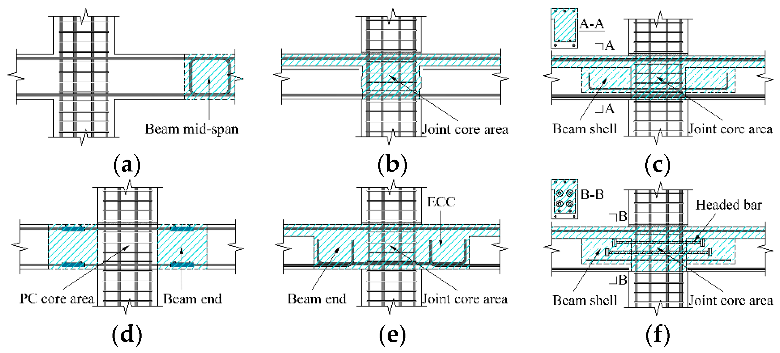
2. A Typical Emulated Connection—Monolithic Precast Joint

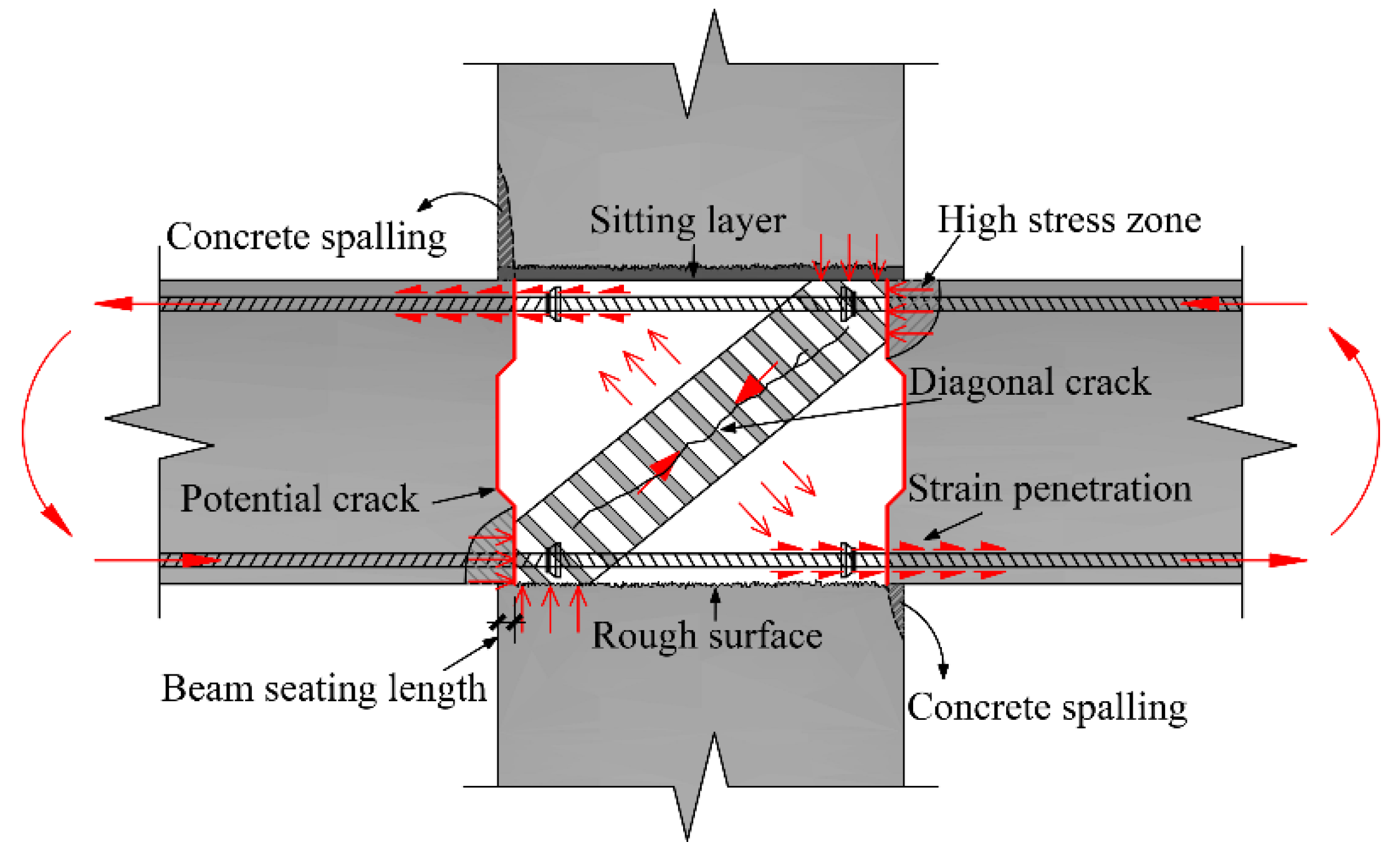
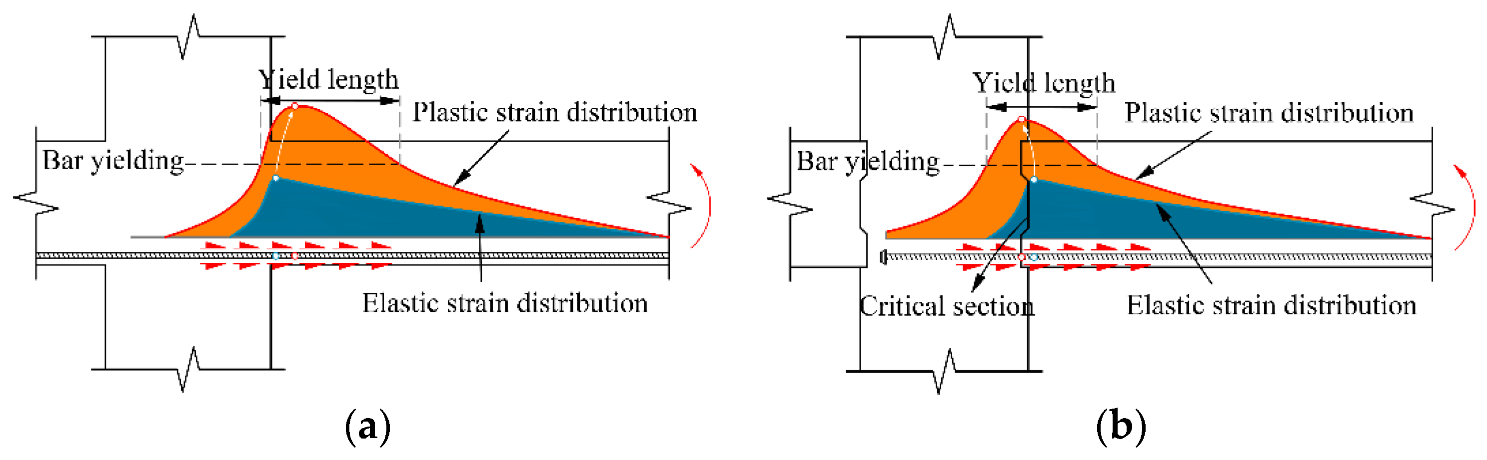
2.1. Force Mechanism

The mechanical behavior of the monolithic precast joint is closely related to its structural form. The typical form is shown in Figure 4, and its main difference with the RC joint is the existence of the interface between new and old concretes. In the past, people took this adverse factor into consideration, made the upper and lower end faces of the precast column into rough surfaces, and set shear keys on the beam end faces to ensure effective transfer of shear forces between the new and old concretes. However, the existence of the interface is also extremely unfavorable for bending failure, and it has rarely been considered until now. As shown in Figure 4, under a rightward horizontal force, the lower side of the right beam is in tension, and the interface between the new and old concretes (a potential crack) is easily pulled off, causing the stress concentration of the longitudinal reinforcement at this interface. With the increase of deformation, the concrete of column protective layer spalls off, and the strain of the rebar penetrates into the core area. The diagonal compression truss (shaded area) formed by the compression zone of the beam and the column is subjected to increased vertical tension, and diagonal cracks are more easily formed. When the load is reversed (reciprocating seismic load), the lower side of the right beam is under compression again. At this time, due to the cracking and local spalling of the concrete, the restraint at the beam end is weakened, which is more likely to cause concentrated damage. In addition, the existence of the beam seating length reduces the effective width of the core area, thus reducing its shear strength [28].
Some testing phenomena well confirm the aforementioned force mechanism. Figure 5 shows the general description of the beam rebar strain of joints which conform to the “strong column weak beam” principle. During the elastic stage, the strain distribution of the rebar is basically consistent with the bending moment distribution, which reaches the maximum at the beam end and decreases rapidly in the core area. During the plastic stage, the strain distribution of monolithic precast joint is significantly different from that of RC joint. The yield range of the RC joint rebar is generally located at the beam end, and the maximum strain is located slightly away from column surface (the concrete spalling area). The yield range of the monolithic precast joint rebar is located at the beam end and in the core area, and the length is relatively short, while the maximum strain of the rebar is located at the column surface or even inside the core area. For precast joints, it is impossible for the bottom longitudinal bar to pass through the core area, and in order to avoid congestion of the rebars, headed bars are often used. However, due to the existence of beam end seating length and the allowable construction error, the anchoring length of the rebar is limited; coupled with the preference for large-diameter and high-strength rebars in the projects in recent years, it is more difficult to ensure the effective bonding of reinforcements.
Figure 6 gives the general description of the joint crack distribution. For RC joints, there are fewer diagonal cracks in the core area, the damage is concentrated in the plastic hinge region at the beam end and bending cracks are scattered in a longer range of the beam (generally, there are more reinforcements in the upper part of the beam, so the lower part of the beam suffers more severe damage). For monolithic precast joints, there are more diagonal cracks in the core area, the damage is concentrated in the tension-compression zone at the beam-column junction and the distribution range of the bending cracks is shorter. Therefore, the energy dissipation capacity of monolithic precast joints is usually weaker than that of RC joints.

2.2. Dimensionless Hysteresis Model

The description of the force mechanism of the typical emulated precast concrete (PCE) joint shows that its main differences with the RC joint include: (1) The interface between the new and old concretes will crack prematurely; (2) The damage is concentrated near the interface, and the concrete at the beam end is more easily crushed, seriously deteriorating the bearing capacity of the joint under large deformation; (3) The concrete damage area and the yield length of the rebar are shorter, and the energy dissipation capacity of the joint is weaker; (4) The pinch effect of the hysteresis curve caused by the rebar slippage is more obvious, and the reloading stiffness is smaller. Based on the above characteristics of the monolithic precast joint, this paper proposes a dimensionless trilinear skeleton model, and the hysteresis curve of the joint can be realized by assigning the corresponding hysteresis rules to the skeleton model.
Figure 7 shows the comparison of the monolithic precast joint skeleton (dashed line) and the RC joint skeleton (solid line). For (1), the monolithic precast joint loses its initial stiffness earlier and begins to yield at point Ap, while the RC joint can maintain the initial stiffness to point Ar. For (2), the RC joint has a longer yield platform until the maximum rotation angle (0.035) specified in the code [29] without strength softening, while the monolithic precast joint quickly softens after reaching the peak strength at point Bp. For (3), the Takeda hysteresis rule is applied to both joints; the area of the hysteresis loop formed by loading from θi to θi+1 shows that the energy dissipation capacity of the monolithic precast joint is poor. For (4), due to the softening of the strength, it is also easy to conclude that the stiffness kip loaded to θi is lower than kir. Therefore, the proposed dimensionless skeleton and its hysteresis model conform to the general nonlinear characteristics of monolithic precast joints.
In order to verify the rationality and universal applicability of the proposed model, the test results of 12 precast joints are processed in a dimensionless manner, and the comparison with the proposed model is shown in Figure 8 (in the test of Yang, a floor exists and the load is applied at beam end, so only the positive results are compared). It can be concluded that the proposed trilinear model well reflects the trend of the skeleton curve of the monolithic precast joint at different loading stages. The insufficient ductility of some joints can also be observed in the comparison. In addition, with the same size and reinforcement design, the bearing capacity of the precast joint may be slightly lower than that of the RC joint, which will also be considered in the subsequent case analysis.

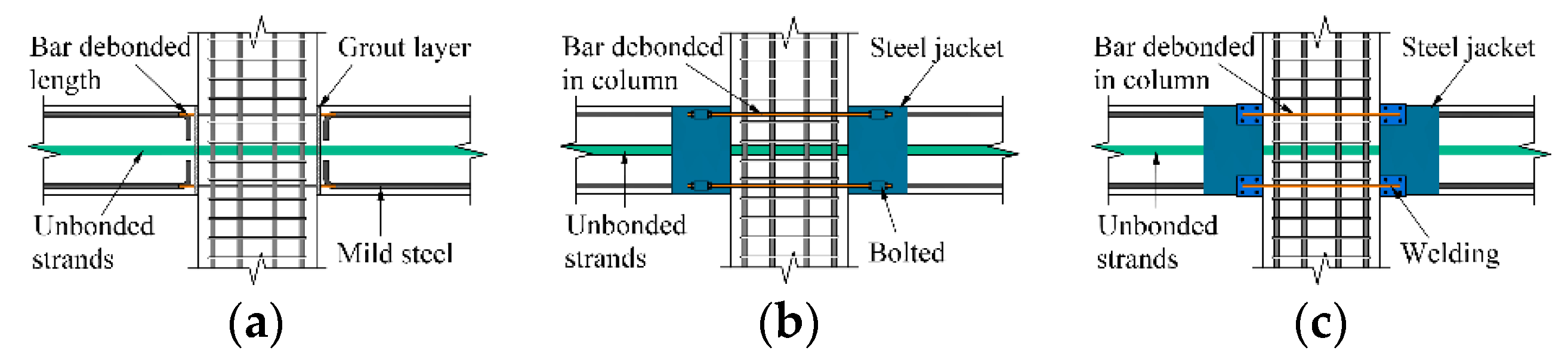
3. A Typical Non-Emulated Connection—Hybrid Precast Prestressed (PCH) Joint

As shown in Figure 9, the skeleton curve of the PCH joint is also expressed by a trilinear model, where the stiffness before yielding ky can be considered to be same as that of the RC joint, and the yield bearing capacity My is designable. The stiffness after yielding ks is mainly affected by the span-depth ratio of beam. It is considered that the joint has a good ductility level, and the decrease of section BC of the bearing capacity is mainly caused by the crushing of concrete in the high stress area at the corner of the beam end. The ideal hysteresis loop of a PCH joint is flag shaped (see Figure 3c). However, in practice, as the proportion of bending moment of the energy dissipation rebars increases, the residual deformation of the joint also increases gradually, and is even close to that of RC joint [23]. In order to reasonably reflect the self-centering characteristic of the joint, this paper sacrifices the accurate estimation of the energy dissipation capacity, and uses the Pivot model [35] to define the hysteresis rule of the joint. The residual deformation θres after unloading is a determined value calculated by an empirical formula [36]. Due to space limitations, we will not introduce the force mechanism of this joint in detail.
In the subsequent analysis, two special cases are considered: (1) When there is no or only a small amount of energy dissipation rebar, the joint will show nonlinear elasticity, which is similar to the situation in Figure 3a; (2) During construction, the energy dissipation rebars are anchored by welding [37] or the unbonded length of the rebars is insufficient, and they will undergo brittle fracture during large deformation.

4. Structural Models and Nonlinear Static Analysis

4.1. Overview of Frame Models

In order to understand the differences in seismic performance between the two types of prefabricated frame structures and the RC frame structures under strong earthquakes, a representative frame structure model was designed. According to the Chinese standard [38], the ground motion design information of this model is: the seismic fortification intensity is 8 degrees, the basic design acceleration is 0.2 g, and the characteristic site period is 0.4 s. The elevation view of the frame is shown in Figure 10: the structure has eight floors, the height of each floor is 3.0 m, and the beam span is 6.0 m. The uniform load on the beam comes from the filler wall load on the beam and the dead load and live load of the half-span (3.9 m) floor, while the concentrated load on the joint comes from the longitudinal wall load. The concrete grade of beams and columns is C40, with a compressive strength of 26.8 N/mm2; the type of rebar is HRB400, and its yield strength is 400 N/mm2 and the ultimate strength is 540 N/mm2 [39]. Section size and reinforcement information is shown in Table 1. In the nonlinear model, both beam hinges and column hinges are set at the member ends. The bearing capacity skeletons of beam hinges are calculated through the sectional reinforcement to define the bending springs and assign the corresponding hysteresis rules (as described in Section 2 and Section 3), while the column hinges adopt P-M2-M3 hinges.
As shown in Table 2, seven nonlinear behaviors of three types of structural forms are considered. As a reference, the RC joint has good performance indexes. For PCE joint, as mentioned before, it yields earlier and the bearing capacity degrades earlier. Considering the insufficient bearing capacity of the PCE joint, the bending moment of its skeleton curve in Figure 7 is reduced by 20%, thereby obtaining the PCE-S joint. In consideration of the insufficient ductility of the PCE joint, the rotation angle of Cp in Figure 7 is reduced to 0.025, thus obtaining the PCE-D joint. PCH joint is designed that the proportion of the bending moment of energy dissipation rebars is about 30% when the joint yields [23]. In consideration of the brittle fracture of reinforcement, it is deemed that the energy dissipation rebars of the PCH joint will all fail when the rotation angle reaches 0.02, and after the failure, the joint will lose the energy dissipation capacity and only the prestressed tendons work. Considering the insufficient configuration of energy dissipation rebars of PCH joint, a PCH-T joint with nonlinear elasticity is designed, which has same parameters as the PCH joint, except that it does not have energy dissipation capacity.

4.2. Pushover Analysis

To grasp the overall force-displacement behavior of structures, a Pushover analysis was first carried out for each frame. The analysis adopted the inverted triangular distribution of lateral loads, and considered the P-Δ effect of structures. During the pushover process, the top displacement of the structure was monitored. When the overall displacement angle of the structure (the ratio of the top displacement to the total height) reached 1/25, the loading was stopped.
In order to compare the pushover results of different structures, four feature points were introduced. (1) Yield point, which means the whole structure yields. This paper adopted the suggestions of Feng et al. [40], and used the farthest point method to define the yield point of the structure. (2) Limit point, which is the corresponding point on the pushover curve when the displacement angle on any floor of the structure reaches 1/50 (the deformation limit in the Chinese standard [38]). (3) Collapse point, which is the corresponding point when the bearing capacity drops to 80% of the limit point, and is used to evaluate the ductility storage capacity of the structure. (4) Column yield point, which is the corresponding point on the pushover curve when the plastic hinge appears on the column for the first time. The pushover curves and characteristic points of various structures are shown in Figure 11.
According to the stiffness before yielding, the emulated frames will show a relatively low second stiffness after the design seismic force, which is especially obvious when the connection strength is insufficient. This is due to the premature cracking of the beam end interface in emulated connections. Therefore, it is necessary to make the structure overstrength when designing such precast frames; otherwise, structural damage will occur under the design earthquake, which will increase the repair cost after earthquakes. The overstrength factor Rs (see Formula (1), where Vp is the peak bearing capacity and Vd is the design seismic force) of the PCE-S frame was calculated as 2.16, so it is recommended that the overstrength factor of emulated frames should be at least 2:
R s = V p V d
Through observing the yield points of various structures, it can be found that the emulated frames yielded before the RC frame, and the reduction of the joint strength of the PCE-S frame caused the structure to yield earlier. The moment when the plastic hinge appears on column is always later than the moment when the structure yields. Thus, when designing according to the principle of strong columns and weak beams, the yield of the frame structure is controlled by the beam, and the earlier yield of the beam in the emulated frames will delay the yield of the structural column. For limit points, the displacement values of each frame are relatively close. The bearing capacities at the limit points of the emulated frames decreased by different degrees, which is caused by the successive strength degradation of frame beams. The bearing capacities of the non-emulated frames are slightly higher at the limit points, but at this time, the bearing capacity of the PCH-F frame is reduced due to the brittle fracture of rebars. When the fracture occurs, the overall displacement angle of the structure is about 1.5%, which is much lower than 2%, the set fracture rotation angle of the joint. Therefore, the ductility of energy dissipation rebars should be paid attention to when designing non-emulated frames. Through comparing the collapse points of structures, it can be found that the ductility storage capacities of the emulated frames are greatly reduced. When the ductility of the joint is less than 2.5%, the structure will collapse quickly after the limit point. Therefore, it is recommended that the monolithic precast joint should at least be able to achieve a rotation angle of 2.5%; otherwise, it should not be promoted in high-intensity areas. In contrast, regardless of the brittle fracture problem of the rebar, the non-emulated frame has certain advantages in resisting a large displacement response.

5. Dynamic Response of Structures

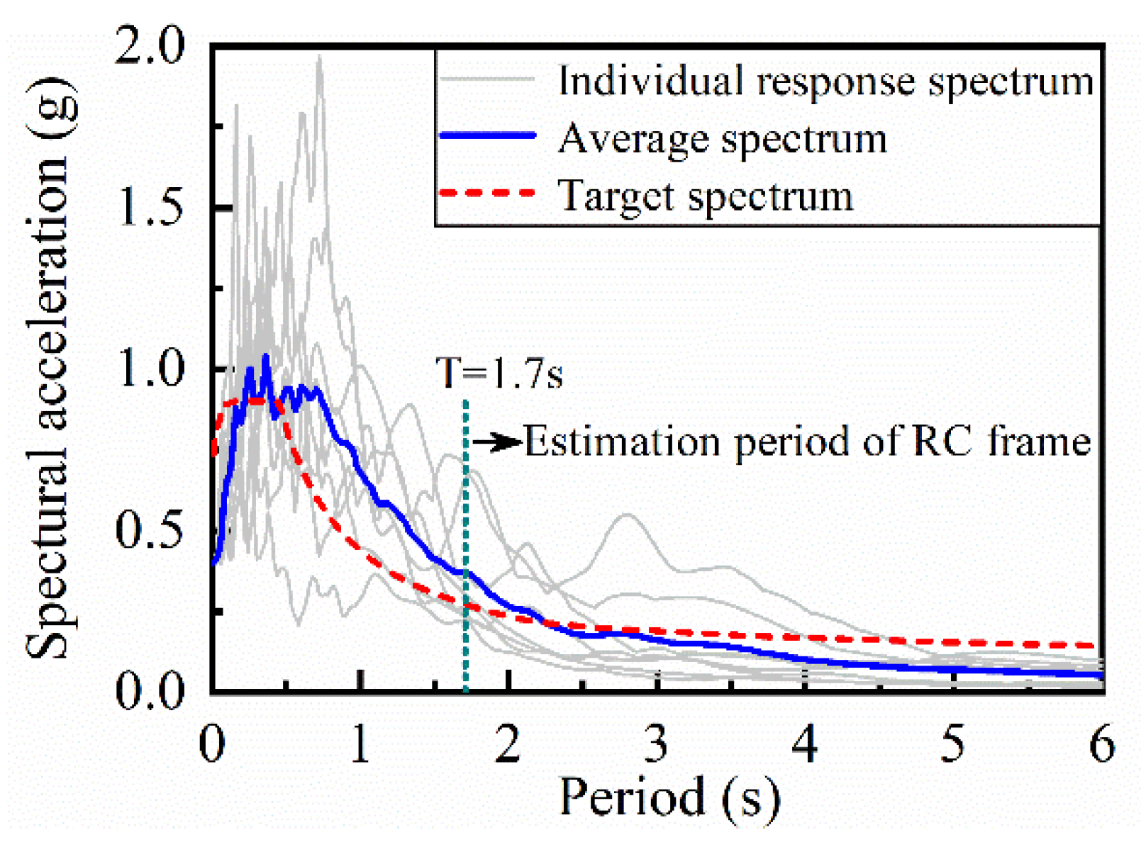
5.1. Ground Motion Information

Eight ground motions are selected from the Peer NGA-West2 database, and their basic information is shown in Table 3. Figure 12 shows the acceleration spectrum of various ground motions obtained by adjusting the amplitude according to the peak acceleration. The period of RC frame estimated by capacity spectrum method under rare earthquakes is 1.7 s. As illustrated, the average spectrum value under this period is very close to the target spectrum value.

5.2. Displacement Response of Structures

In order to understand the dynamic response characteristics of different precast frames, the direct integration method was used for dynamic time history analysis under rare earthquakes (PGA: 400 gal) and extremely rare earthquakes (PGA: 600 gal). If the story drift of a certain floor exceeds the rotation angle value of the aforementioned feature point C, the structure will be considered as the total collapse. In rare earthquakes, only the PCE-D frame collapsed under Wave 1, so the reduction of joint ductility will cause the most adverse effect on the structure. Figure 13a,c plot the average maximum floor displacement of each frame under Waves 2–8 in rare earthquakes. Compared with the RC frame, the deformation of upper floors of emulated frames increase significantly, while the deformation of each floor of non-emulated frames generally increases, and their peak displacement response are higher than that of emulated frames. Under extremely rare earthquakes, the PCE-D frame collapses under Waves 1–3, and the PCH-F frame collapses under Waves 1 and 2. All precast frames under Wave 1 exceed the code displacement limit of 1/50. Figure 13b,d show the average maximum floor displacement of each frame under Waves 4–8 in extremely rare earthquakes; the maximum story drift of each structure shows similar laws. Therefore, attention should be paid to the displacement response of the upper structure for emulated frames, and the damage of structural components and non-structural members under large floor deformation for the non-emulated frames.
The displacement response characteristics of different precast frames are described by taking the top displacement time history of Wave 2 (PGA: 600 gal) as an example. As shown in Figure 14, the peak displacement of PCE frame is significantly higher than that of the RC frame. In addition to the increase of the peak response, the vibration amplitude of PCH frame also generally increases in the time range. This earthquake ended at 40 s; the RC frame and PCE frame became static immediately after the earthquake, but the PCH frame still underwent a period of small vibration due to insufficient energy dissipation capacity before being in static. Due to the self-centering feature of joints, the residual deformation of the PCH frame is small.

5.3. Ductility Demands of Frame Beams and Columns

The ductility demands of the beam end plastic hinge zones of various frames are compared by taking the time history rotation angle at the beam end of the top floor under Wave 4 (PGA: 600 gal) as an example. As shown in Figure 15, under the action of gravity load at the initial moment, the beam end has a certain elastic deformation. The time when peak rotation angle of each beam end appears is basically the same, and the size law is the same as the top displacement response in Figure 13. The beam end rotation angle of the emulated frames is slightly higher than that of the RC frame in both positive and negative directions throughout the time history. The beam end rotation angle of the non-emulated frames increases more significantly than the RC frame.
Figure 16 compares the ductility demands at column bottom of first floor under Wave 2 (PGA: 400 gal). Although emulated frames can delay the emergence of column hinges to some extent, once the earthquake intensity is high, the ductility demands of the column will still be higher than that of the RC frame. For non-emulated frames, the rotation angle of the columns increased significantly, and the PCH-T frame columns underwent the most severe damage. This is because if the energy dissipation capacities of the connecting joints are insufficient, the seismic input energy will be dissipated by the damage of the columns, which is extremely detrimental for the post-earthquake repair of the structure.

5.4. Residual Deformation of Structures

Figure 17 summarizes the residual deformation values of various frame structures of seven ground motions in case of rare earthquakes and extremely rare earthquakes. It can be concluded that the post-earthquake residual deformation of the emulated frames are basically equivalent to that of the RC frame, while the overall deformation of non-emulated frames can recover to within 1/550 (the limit story drift under the design earthquake), except for structural failure. However, it should be noted that the PCH-T frame joints can fully restore after an earthquake, and its residual deformation is caused by the unrecoverable damage of the column, which violates the concept of post-earthquake repairability of such structure.

6. Discussion

Whether PC buildings can replace RC buildings in high-intensity areas has always been a controversial issue. In recent years, some scholars suggested that the vertical components of PC buildings should be cast in situ to reduce the risk of serious casualties caused by structural collapse. However, such conservative practices have become an obstacle to the development of PC buildings. With an increasing number of experimental studies, some differences between PC joints and RC joints have emerged. Obviously, it is unreasonable and inaccurate to continue to use RC structure models to analyze PC structures. Engineers are eager to understand the impact of these differences and the issues they should pay attention to when designing PC structures. These are the motivations of this work.
The nonlinear analysis models proposed in this paper for two types of typical PC joints are the results of a large amount of experimental work, so they are generally representative. In the nonlinear analysis, some possible degradation effects of PC joints are fully considered. Although some of the parameters are empirically defined, the analytical methods and results in this paper are still of great reference value. Engineering designers can extend this method to the nonlinear analysis of actual three-dimensional PC structures. If a new PC joint is developed in the future, some test results of the new joint can also be compared with a certain situation considered in this paper, so as to judge its engineering application value. These are the significance of this research.

7. Conclusions

This paper researches the differences in the nonlinear behaviors between two types of typical prefabricated joints and RC joints, and analyzes the influence of these differences on the seismic performance of structures. The following main conclusions are obtained through research and analysis:
  • The main difference between emulated connection joints and RC joints is that they will crack early and cause premature degradation of bearing capacity, which is mainly due to the presence of the interface between new and old concretes at the beam-column junction of the precast joints. The use of a dimensionless trilinear skeleton model can well describe the differences in nonlinear behavior between the emulated connection joints and the RC joints.
  • From the perspective of the force-deformation relationship, the main difference between precast frames and the RC frame is the size of the peak bearing capacity and the degradation speed of the bearing capacity beyond the limit point. It is recommended that the minimum overstrength factor of the emulated frame should be 2 in the design.
  • Compared with the RC frame, the displacement response of the upper floors of emulated frames increases significantly, and the displacement response of various floors of non-emulated frames increases generally. Compared with an insufficient bearing capacity, an insufficient joint ductility will cause the most adverse effect on the collapse resistance of the structure, so that the joints with a damage rotation angle less than 2.5% are not recommended in high-intensity areas.
  • The post-earthquake residual deformation of the non-emulated frames is small, but the ductility demands for the joints are higher. Therefore, more attention should be paid to the brittle fracture and fatigue failure of energy dissipation rebars caused by the large deformation for this type of connection. When energy dissipation rebars are not installed, this type of frame overly relies on the damage of structural columns to dissipate seismic energy, which will also cause the structure to be irreparable after the earthquake. Therefore, the structural system containing only prestressed tendons is not recommended in high-intensity areas.

Author Contributions

Conceptualization, B.S. and D.D.; investigation, W.L. and Y.W.; validation, S.W.; formal analysis, Y.W. and D.F.; supervision, W.L.; Writing—original draft preparation, B.S. and D.D.; Writing—review and editing, D.F. and S.W. All authors have read and agreed to the published version of the manuscript.

Funding

This research was funded by the National Natural Science Foundation of China, grant numbers 51678301, 51808291 and 51678302; and the Six talent peaks project in Jiangsu Province, grant number JY-022.

Conflicts of Interest

The authors declare no conflict of interest.

References

  1. Kurama, Y.C.; Sritharan, S.; Fleischman, R.B.; Restrepo, J.I.; Henry, R.S.; Cleland, N.M.; Ghost, S.K.; Bonelli, P. Seismic-resistant precast concrete structures: State of the art. J. Struct. Eng. 2018, 144. [Google Scholar] [CrossRef] [Green Version]
  2. Wu, G.; Feng, D.C. Research progress on fundamental performance of precast concrete frame beam-to-column connections. J. Build. Struct. 2018, 39, 1–16. (In Chinese) [Google Scholar]
  3. Sezen, H.; Whittaker, A.S. Seismic performance of industrial facilities affected by the 1999 Turkey earthquake. J. Perform. Constr. Facil. 2006, 20, 28–36. [Google Scholar] [CrossRef]
  4. Xu, Y.L.; Gong, Y.N. Investigation of collapse of teaching building during the Wenchuan Earthquake: Third anniversary memorial of 5·12 Wenchuan Earthquake. J. Build. Struct. 2011, 32, 9–16. (In Chinese) [Google Scholar]
  5. Fan, J.J.; Feng, D.C.; Wu, G.; Hou, S.T.; Lu, Y. Experimental study of prefabricated RC column-foundation assemblies with two different connection methods and using large-diameter reinforcing bars. Eng. Struct. 2020, 205, 110075. [Google Scholar] [CrossRef]
  6. Priestley, M.J.N. Direct displacement-based design of precast/prestressed concrete building. PCI J. 2002, 47, 66–79. [Google Scholar] [CrossRef]
  7. Park, R. A perspective on the seismic design of precast concrete structures in New Zealand. PCI J. 1995, 40, 40–60. [Google Scholar] [CrossRef]
  8. Fan, J.J.; Wu, G.; Feng, D.C.; Zeng, Y.H.; Lu, Y. Seismic performance of a novel self-sustaining beam-column connection for precast concrete moment-resisting frames. Eng. Struct. 2020, 222, 111096. [Google Scholar] [CrossRef]
  9. Gao, J.; Tian, C.Y.; Hao, W.; Tan, Y.A. Experimental study on seismic behavior of precast concrete layered slab and beam to column interior joints. J. Build. Struct. 2015, 36, 203–209. (In Chinese) [Google Scholar]
  10. Guan, D.; Jiang, C.; Guo, Z.; Ge, H. Development and seismic behavior of precast concrete beam-to-column connections. J. Earthq. Eng. 2016, 22, 234–256. [Google Scholar] [CrossRef]
  11. Alcocer, S.M.; Carranza, R.; Perez-Navarrete, D.; Martinez, R. Seismic tests of beam-to-column connections in a precast concrete frame. PCI J. 2002, 47, 70–89. [Google Scholar] [CrossRef]
  12. Yan, Q.; Chen, T.; Xie, Z. Seismic experimental study on a precast concrete beam-column connection with grout sleeves. Eng. Struct. 2018, 155, 330–344. [Google Scholar] [CrossRef]
  13. Lu, C.; Dong, B.; Pan, J.; Shan, Q.; Hanif, A.; Yin, W. An investigation on the behavior of a new connection for precast structures under reverse cyclic loading. Eng. Struct. 2018, 169, 131–140. [Google Scholar] [CrossRef]
  14. Im, H.J.; Park, H.G.; Eom, T.S. Cyclic loading test for reinforced-concrete-emulated beam-column connection of precast concrete moment frame. ACI Struct. J. 2013, 110, 115–126. [Google Scholar]
  15. Ertas, O.; Ozden, S.; Ozturan, T. Ductile connections in precast concrete moment resisting frames. PCI J. 2006, 51, 66–76. [Google Scholar] [CrossRef]
  16. Zhong, Y.; Xiong, F.; Chen, J.; Deng, A.; Chen, W.; Zhu, X. Experimental study on a novel dry connection for a precast concrete beam-to-column joint. Sustainability 2019, 11, 4543. [Google Scholar] [CrossRef] [Green Version]
  17. Li, S.; Li, Q.; Zhang, H.; Jiang, H.; Yan, L.; Jiang, W. Experimental study of a fabricated confined concrete beam-to-column connection with end-plates. Constr. Build. Mater. 2018, 158, 208–216. [Google Scholar]
  18. Aninthaneni, P.K.; Dhakal, R.P.; Marshall, J.; Bothara, J. Experimental investigation of “dry” jointed precast concrete frame sub-assemblies with steel angle and tube connections. Bull. Earthq. Eng. 2020, 18, 3659–3681. [Google Scholar] [CrossRef]
  19. Jin, K.; Song, S.; Kitayama, K.; Hao, L. Detailed evaluation of the ultimate flexural states of beams in unbonded precast prestressed concrete frames. Bull. Earthq. Eng. 2019, 17, 1495–1519. [Google Scholar] [CrossRef]
  20. Morgen, B.G.; Kurama, Y.C.; Asce, M. Seismic design of friction-damped precast concrete frame structures. J. Struct. Eng. 2007, 133, 1501–1511. [Google Scholar] [CrossRef]
  21. Hu, G.; Huang, W.; Xie, H. Mechanical behavior of a replaceable energy dissipation device for precast concrete beam-column connections. J. Constr. Steel Res. 2020, 164, 105816. [Google Scholar] [CrossRef]
  22. Priestley, M.J.N. The PRESSS program—Current status and proposed plans for phase III. PCI J. 1996, 41, 22–40. [Google Scholar] [CrossRef]
  23. Ozden, S.; Ertas, O. Behavior of unbonded, post-tensioned, precast concrete connections with different percentages of mild steel reinforcement. PCI J. 2007, 52, 32–44. [Google Scholar] [CrossRef]
  24. Wang, H.; Marino, E.M.; Pan, P.; Liu, H.; Nie, X. Experimental study of a novel precast prestressed reinforced concrete beam-to-column joint. Eng. Struct. 2018, 156, 68–81. [Google Scholar] [CrossRef]
  25. Feng, D.C.; Wu, G.; Lu, Y. Finite element modelling approach for precast reinforced concrete beam-to-column connections under cyclic loading. Eng. Struct. 2018, 174, 49–66. [Google Scholar] [CrossRef] [Green Version]
  26. Feng, D.C.; Wang, Z.; Wu, G. Progressive collapse performance analysis of precast reinforced concrete structures. Struct. Des. Tall Build. 2019, 28, e1588. [Google Scholar] [CrossRef]
  27. Feng, D.C.; Wang, Z.; Cao, X.Y.; Wu, G. Damage mechanics-based modeling approaches for cyclic analysis of precast concrete structures: A comparative study. Int. J. Damage Mech. 2020, 29, 965–987. [Google Scholar] [CrossRef]
  28. Eom, T.S.; Park, H.G.; Hwang, H.J.; Kang, S.M. Plastic hinge relocation methods for emulative PC beam–column connections. J. Struct. Eng. 2016, 142, 04015111. [Google Scholar] [CrossRef]
  29. ACI Innovation Task Group 1 and Collaborators and ACI Committee 374. T1.1-01/T1.1R-01: Acceptance Criteria for Moment Frames Based on Structural Testing; ACI: Farmington Hills, MI, USA, 2001. [Google Scholar]
  30. Wu, C.X.; Zhou, Y.; Lai, W.S.; Zhang, Y.F.; Deng, X.S. Experiment on seismic performance of cast-in-situ and prefabricated concrete frame structure joints. J. Archit. Civ. Eng. 2015, 32, 60–66. (In Chinese) [Google Scholar]
  31. Shariatmadar, H.; Zamani, B.E. An investigation of seismic response of precast concrete beam to column connections: Experimental study. Asian J. Civ. Eng. 2014, 15, 849–867. [Google Scholar]
  32. Liu, L.; Huang, X.K.; Tian, C.Y.; Yin, X.W.; Li, R.; Li, G.Q. Experimental study on seismic performance of precast RC frame joints with HRB500 high strength rebars of large diameter and spacing. J. Build. Struct. 2016, 37, 247–254. (In Chinese) [Google Scholar]
  33. Zhang, B. Investigations on Seismic Behavior of Precast Concrete Frames. Ph.D. Thesis, Tongji University, Shanghai, China, 2012. (In Chinese). [Google Scholar]
  34. Yang, H. Experimental Study on Seismic Performance of Precast Concrete Frame Joints. Master’s Thesis, North University of Technology, Beijing, China, 2014. (In Chinese). [Google Scholar]
  35. Aninthaneni, P.K.; Dhakal, R.P.; Marshall, J.; Bothara, J. Nonlinear cyclic behavior of precast concrete frame sub-assemblies with “dry” end plate connection. Structures 2018, 14, 124–136. [Google Scholar] [CrossRef]
  36. Ozden, S.; Ertas, O. Modeling of pre-cast concrete hybrid connections by considering the residual deformations. Int. J. Phys. Sci. 2010, 5, 781–792. [Google Scholar]
  37. Rodriguez, M.E.; Torres-Matos, M. Seismic behavior of a type of welded precast concrete beam-column connection. PCI J. 2013, 58, 81–94. [Google Scholar] [CrossRef]
  38. China Academy of Building Research. GB 50011-2010, Code for Seismic Design of Buildings; China Architecture and Building Research: Beijing, China, 2010. (In Chinese) [Google Scholar]
  39. China Academy of Building Research. GB 50010-2010, Code for Design of Concrete Structures; China Architecture and Building Research: Beijing, China, 2010. (In Chinese) [Google Scholar]
  40. Feng, P.; Qiang, H.; Ye, L. Discussion and definition on yield points of materials, members and structures. Eng. Mech. 2017, 34, 36–46. (In Chinese) [Google Scholar]
Figure 1. Emulated connection forms: (a) the connection located at the beam mid-span; (b) the connection located in the core area; (c) the connection located in the beam shell and the core area; (d) the connection located at the beam end; (e) the connection located at the beam end and in the core area; (f) the connection attached with headed bars.
Applsci 10 08280 g001
Figure 2. Non-emulated connection forms: (a) mild steel located inside the beam; (b) mild steel bolted to the beam side; (c) mild steel welded to the beam side.
Applsci 10 08280 g002
Figure 3. Description of hysteresis characteristics: (a) nonlinear elastic system; (b) tension-compression yield system; (c) hybrid connection system.
Applsci 10 08280 g003
Figure 4. Force mechanism of the monolithic precast joint.
Applsci 10 08280 g004
Figure 5. Comparison of rebar strain: (a) RC joint; (b) monolithic precast joint.
Applsci 10 08280 g005
Figure 6. Comparison of crack distribution: (a) RC joint; (b) monolithic precast joint.
Applsci 10 08280 g006
Figure 7. Dimensionless models of PCE joints and RC joints.
Applsci 10 08280 g007
Figure 8. Validation of dimensionless model: (a) Wu et al. [30]; (b) Shariatmadar and Zamani [31]; (c) Liu et al. [32]; (d) Zhang [33]; (e)–(g) Yang [34].
Applsci 10 08280 g008
Figure 9. Calculation model of PCH joints.
Applsci 10 08280 g009
Figure 10. Frame load and plastic hinge arrangement.
Applsci 10 08280 g010
Figure 11. Pushover curves of frames: (a) Comparison of emulated frames and the RC frame; (b) comparison of non-emulated frames and the RC frame.
Applsci 10 08280 g011
Figure 12. Acceleration spectrums of selected ground motions.
Applsci 10 08280 g012
Figure 13. The distribution of maximum floor displacement under rare and extremely rare earthquakes: (a) Emulated frames under rare earthquakes; (b) Emulated connection frames under extremely rare earthquakes; (c) Non-emulated frames under rare earthquakes; (d) Non-emulated frames under extremely rare earthquakes.
Applsci 10 08280 g013
Figure 14. Time history of the top displacement under Wave 2 (PGA: 600 gal): (a) RC frame; (b) PCE frame; (c) PCH frame.
Applsci 10 08280 g014
Figure 15. Time history of the rotation angle at beam end of top floor under Wave 4 (PGA: 600 gal): (a) Comparison between emulated frames and the RC frame; (b) Comparison between non-emulated frames and the RC frame.
Applsci 10 08280 g015
Figure 16. Time history of the rotation angle at column bottom of first floor under Wave 2 (PGA: 400 gal): (a) Comparison between emulated frames and the RC frame; (b) Comparison between non-emulated frames and the RC frame.
Applsci 10 08280 g016
Figure 17. Residual deformation at top floor of various structures: (a) under rare earthquakes; (b) under extremely rare earthquakes.
Applsci 10 08280 g017
Table 1. Reinforcement of frame sections.
SectionSide ColumnMiddle ColumnBeam on Floors 1–6Beam on Floors 7–8
Unilateral reinforcement4 Applsci 10 08280 i001254 Applsci 10 08280 i001283 Applsci 10 08280 i001223 Applsci 10 08280 i00120
Reinforcement area (mm2)5892738922811884
Reinforcement ratio1.6%1.5%1.2%1.0%
Reinforcement diagram Applsci 10 08280 i002 Applsci 10 08280 i003 Applsci 10 08280 i004 Applsci 10 08280 i005
Table 2. The connection forms researched.
Structure FormCast-In-Situ ConnectionEmulated ConnectionsNon-Emulated Connections
AbbreviationRCPCEPCE-SPCE-DPCHPCH-FPCH-T
Bearing capacity×
Ductility capacity××
Energy dissipation capacity×
Self-centering capacity××××
Note: √ means good performance, ○ means general performance and × means poor performance.
Table 3. Basic information of selected ground motions.
NumberSeismic EventYearEarthquake Magnitude (Mw)Epicentral Distance (km)Recorded Station
1Taiwan SMART1(45)19867.356.01SMART1 C00
2Loma Prieta19896.9341.88APEEL 10-Skyline
3Friuli Italy-0119766.533.4Codroipo
4Kern County19527.3638.89Taft Lincoln School
5Loma Prieta19896.9352.68APEEL 2E Hayward Muir Sch
6Spitak Armenia19886.7723.99Gukasian
7Superstition Hills-0219876.5427Calipatria Fire Station
8San Fernando19716.6127.4Lake Hughes #1
Publisher’s Note: MDPI stays neutral with regard to jurisdictional claims in published maps and institutional affiliations.

