Featured Application
This method presents a new way for the rapid and area-specific printing of protein-immobilized calcium phosphate, which could potentially be used for the surface functionalization of medical devices and human tissues.
Abstract
The rapid and area-specific printing of calcium phosphate with superior biocompatibility and osteoconductivity is a useful technique for the surface functionalization of biomedical devices. We recently demonstrated the laser-induced forward transfer (LIFT) of a brittle calcium phosphate film onto a soft and shock-absorbing polydimethylsiloxane (PDMS) substrate. In this work, a new LIFT using an optically transparent PDMS-coated stamp, which we hereafter call LIFT with optical stamp (LIFTOP), was introduced to achieve the transfer of brittle films to harder substrates. Cell adhesion protein fibronectin-immobilized calcium phosphate films (Fn-CaP) were prepared on the optical stamp through a biomimetic process. Then, the irradiation of a single laser pulse transferred the Fn-CaP film from the optical stamp onto relatively hard substrates, polyethylene terephthalate and human dentin. As a result of this LIFTOP process, Fn-CaP microchips with a shape corresponding to the laser beam spot were printed on the substrates. Cross-sectional observation of the interface between the Fn-CaP microchip and the dentin substrate revealed good attachment between them without obvious gaps for the most part.
1. Introduction
Laser processing technologies make it possible to microfabricate a variety of materials without using vacuum and the harmful chemicals required for photolithography. By taking advantage of such features, laser-precise microfabrication has received a lot of attention in optoelectronics, biomedical fields, and so forth. While most of them are laser removal and surface modification technologies, since the 1980s, laser-induced forward transfer (LIFT) has been developed as a simple and unique additive manufacturing method [1]. By using LIFT, various substances, such as metals [2,3,4,5], semiconductors [6], oxides [7,8,9], silver nanopaste [10,11,12], graphene [13], and biomaterials [14,15,16], can be printed even at a micron/submicron resolution under atmospheric and room-temperature conditions. The LIFT process generally involves the irradiation of a single laser pulse through a transparent support onto a donor material or a sacrificial layer that absorbs laser light, leading to laser-induced phenomena such as heating, melting, ablation, etc. In general, a laser-induced change induces a transient excitation field with high temperature and/or pressure, thus transferring the donor material toward a receiver substrate placed against the donor. With the advancement of beam delivery technologies such as digital mirror device and visualization methods, LIFT methods are progressing with higher accuracies and better phenomena elucidation [17,18,19,20,21,22].
Calcium phosphate (CaP) is the main inorganic constituent of bones and teeth. Certain types of CaP compounds, including hydroxyapatite, β-tricalcium phosphate, and octacalcium phosphate, exhibit both good biocompatibility and osteoconductivity [23]. Thus, various synthesis methods of CaP nanomaterials, including nanorods and nanowires [24] and nanopowders [25], have been developed [26]. Various methods of CaP coatings, such as plasma spray, pulsed laser deposition, and biomimetic processes [27,28,29], have also been developed to improve biocompatibility and osteoconductivity of medical devices. Among these CaP coating techniques, biomimetic processes are useful to produce multifunctional CaP coatings combined with biofunctional substances, such as proteins, since they are conducted under mild pseudo-physiological conditions [30]. However, conventional biomimetic processes are generally incapable of area-specific coating and take several hours to a few days [30] with a few exceptions [31].
In our previous work, we demonstrated the rapid printing of cell adhesion protein fibronectin (Fn)-immobilized hydroxyapatite (Fn-apatite) microchips by applying LIFT to a shock-absorbing polydimethylsiloxane (PDMS) substrate [16]. Further, the conducted CHO-K1 cell culture experiments revealed the good cytocompatibility of the Fn-apatite microchips. However, a hard receiver substrate was not applicable to this technique; an applicable receiver substrate has been limited to a soft and shock-absorbing material, PDMS, owing to the brittle nature of apatite.
In the present study, a novel LIFT process using a soft and shock-absorbing PDMS-coated transparent support, which we call LIFT with optical stamp (LIFTOP), was developed to print brittle CaP microchips even onto hard receiver substrates. Fn-immobilized CaP (Fn-CaP) donor films were prepared on an optical stamp (PDMS-coated transparent support) through the biomimetic process. Successful printing of the Fn-CaP microchips with a shape corresponding to a laser spot was demonstrated onto relatively hard receiver substrates, polyethylene terephthalate (PET) and human dentin, via the LIFTOP process. A cross-sectional interface between the Fn-CaP microchip and dentin was observed using a scanning electron microscope (SEM), revealing a good attachment without obvious gaps.
2. Experimental
2.1. Preparation of Fn-CaP Donor Films on Optical Stamp Using the Biomimetic Process
Fn-CaP donor films were prepared on an optical stamp through a precursor-assisted biomimetic process [30,32], as detailed in the previous report [16]. Different from the previous work [16], a PET substrate was used as a transparent support, one-side of which was coated with a 1-mm-thick PDMS sheet. Hereafter, the PDMS-coated PET substrate is referred to as an optical stamp (denoted as PDMS/PET). Then, a thin carbon film with a thickness of about 50 nm was prepared on the PDMS surface of the optical stamp via vapor deposition. The thin carbon film was formed as a sacrificial layer, which absorbs laser light, thereby causing laser-induced forward transfer of the Fn-CaP film. The carbon-preformed optical stamp (denoted as C/PDMS/PET) was subjected to the oxygen plasma treatment for surface activation. The plasma-treated C/PDMS/PET substrate was alternately dipped in 0.2 M CaCl2 and 0.2 M K2HPO4·3H2O aqueous solutions for CaP precoating and, subsequently, immersed at 25 °C for 5 h in a supersaturated CaP solution for film growth. Fn (from bovine plasma, Sigma-Aldrich) was supplemented at a final concentration of 40 μg/mL to the CaCl2 and K2HPO4·3H2O solutions and to the supersaturated CaP solution for Fn immobilization within the film [16]. Fn is a biofunctional protein, which promotes cell adhesion and spreading. We previously confirmed that Fn is immobilized within apatite films formed using a similar precursor-assisted biomimetic process [32]. After the film formation, the substrate was washed with ultrapure water and freeze-dried before use (denoted as Fn-CaP/C/PDMS/PET donor sample). For comparison, a Fn-CaP film was prepared using a carbon-coated PET substrate without the PDMS layer, which is denoted as Fn-CaP/C/PET donor sample. The surface morphology of donor films was monitored by field emission-SEM (S-4800, Hitachi High-Tech Corporation, Tokyo, Japan). The film thickness was also estimated through the depth measurements of the laser-irradiated spots on the donor films after the LIFTOP or LIFT process.
2.2. LIFTOP Process for the Rapid Printing of Fn-CaP Films
Figure 1 shows the LIFTOP system used in the present work. First, the optical stamp with the donor film, namely the Fn-CaP/C/PDMS/PET donor sample was contacted with a receiver substrate. As receiver substrates, PET and human dentin were tested. The human dentin substrates were prepared from natural human teeth following an established protocol [33] with the approval by the ethical review boards of both the Hokkaido University Hospital for clinical research (approval No. 16–72) and the National Institute of Advanced Industrial Science and Technology (AIST). A high-repetition nanosecond pulsed laser (Navigator, Spectra-Physics, Santa Clara, CA, USA; λ = 1064 nm, 10 kHz, full width at half maximum 40 ns) was used as a light source. The laser pulses with a spatially and temporally Gaussian shape were focused and scanned with galvanometer mirrors and fθ lens system. Here, it should be mentioned that the Fn-CaP donor film and the PET receiver substrate were placed in direct contact in our LIFTOP system to reduce the film flight time and the impact upon transfer. In order to clarify the effect of the optical stamp on the film transfer quality, the Fn-CaP/C/PET donor sample without PDMS was also subjected to the LIFT process for comparison.
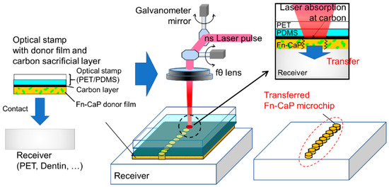
Figure 1.
Schematic of the laser-induced forward transfer with optical stamp (LIFTOP) process. In the present work, the fibronectin-immobilized calcium phosphate (Fn-CaP) donor film was prepared on the carbon-coated optical stamp by the biomimetic process, which was then contacted with a receiver substrate (left). The irradiation of each nanosecond (ns) laser pulse caused strong laser absorption at the carbon sacrificial layer, leading to the donor film transfer onto the receiver substrate with a micropattern corresponding to the laser beam spot (right).
2.3. Surface Morphology Evaluation of the Donor Films and Transferred Fn-CaP Microchips on the PET and Human Dentin Receiver Substrates
The surface morphology of the donor films and transferred Fn-CaP microchips was evaluated using a confocal laser scanning microscope (VK-X1000, Keyence, Osaka, Japan) and field emission-SEM. From the confocal laser scanning microscopic measurements of the donor films, the presence of cracking and the cross-sectional profile at the laser spot were measured. The size of the transferred Fn-CaP microchips was also estimated by the confocal laser scanning microscopic measurements. Prior to the SEM analysis, the sample was coated with a thin gold film using a DC magnetron sputtering coater (SC-701MkII, Sanyu Electron Co., Ltd., Tokyo, Japan), which prevented the sample charge-up during the SEM observation.
2.4. Cross-Sectional Observation of the Transferred Fn-CaP Microchips on the Human Dentin Receiver
From the Fn-CaP microchip transferred onto the dentin receiver substrate, a cross-sectional sample was prepared through focused ion beam (FIB) processing using a Ga+ ion source (FB-2100, Hitachi High-Tech Corporation, Tokyo, Japan). In the FIB processing, the substrate was coated with tungsten (W) using W(CO)6 gas to protect its surface. The obtained cross-sectional sample was subjected to the SEM observation for the evaluation of the Fn-CaP/dentin interface.
3. Results and Discussion
3.1. Donor Film Characterization
Figure 2 shows SEM images of the surfaces of the (a,b) Fn-CaP/C/PDMS/PET and (c,d) Fn-CaP/C/PET donor samples. By comparing Figure 2a,c, a thick crack was observed on the former film only. Such a crack formation was not obvious when the Fn-CaP/C/PDMS/PET samples were air-dried at room temperature (not freeze-dried). This suggests that cracks might be generated by freeze-drying in the Fn-CaP film on the C/PDMS/PET support most likely due to the relatively high coefficient of thermal expansion of PDMS.
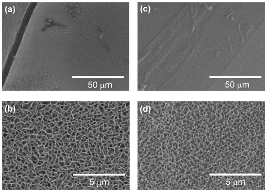
Figure 2.
SEM images of the surfaces of the (a,b) fibronectin-immobilized calcium phosphate (Fn-CaP) on the carbon-preformed optical stamp (Fn-CaP/C/PDMS/PET) and (c,d) Fn-CaP on the carbon-preformed PET (Fn-CaP/C/PET) donor samples.
The high-magnification SEM images (Figure 2b,d) showed that the Fn-CaP film surfaces have a porous structure, which is a typical morphology of CaP films prepared using the biomimetic process [16]. There is no apparent difference in the surface structure between these substrates with and without the PDMS layer. This result is natural from the fact that both films grew on the carbon-coated substrates and the PDMS layer was located under the carbon layer (not exposed to the surface during the film growth). Our previous work confirmed the existence of a hydroxyapatite crystalline phase in the Fn-CaP film prepared under the same conditions on the C/PET support by thin-film X-ray diffraction measurements [16]. Based on these results, it was deduced that both Fn-CaP donor films have a hydroxyapatite crystalline phase.
3.2. Optical Stamp Effects on the Film Transfer
In our previous paper [16], we performed LIFT of Fn-apatite donor films prepared on a hard C/PET support onto a soft shock-absorbing PDMS receiver. As a result, even the brittle Fn-apatite films could be transferred with keeping their filmy shape. However, in our previous method using the C/PET support, the transferred microchips were crushed on a hard receiver substrate, such as silica glass and PET, and high-quality film transfer was not possible. Therefore, in this work, aiming at the development of a novel technology that can be applied even to hard receiver substrates, PDMS, which is soft and has excellent shock absorption, was introduced for the first time to the transparent support side to prevent the crushing of the donor films during transfer.
Figure 3a shows schematic image of the LIFTOP process and a confocal laser scanning microscopic image of the Fn-CaP microchips transferred onto the PET receiver substrate using the LIFTOP process. For comparison, the Fn-CaP donor film was transferred by the LIFT process without the optical stamp as shown in Figure 3b. The transfer of the Fn-CaP film with retaining its filmy state was confirmed in the case of the LIFTOP process. Since each laser pulse induces the transfer of the donor film to the receiver substrate [16], the transferred Fn-CaP microchips had a shape corresponding to the laser beam spot. On the contrary, most of the donor film was crushed and deposited sparsely on the PET receiver substrate in the latter case. Therefore, the usage of the PDMS-coated support, namely optical stamp, is effective for higher quality film transfer onto the hard substrate.
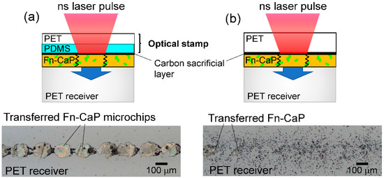
Figure 3.
(a) Schematic image of the LIFTOP process (upper) and a confocal laser scanning microscopic image of the Fn-CaP microchips transferred onto the PET receiver substrate by the LIFTOP process (lower). For comparison, the Fn-CaP film was transferred by the laser-induced forward transfer process without the optical stamp, as shown in (b).
3.3. A Model for the LIFTOP Process of the Fn-CaP Film
Why is the LIFTOP process able to transfer brittle materials even onto hard receiver substrates while maintaining their film shape? One of the possible explanations is shown in Figure 4, which shows the possible models for the Fn-CaP film transfer by the (a) LIFTOP process and (b) LIFT. For both cases, a single nanosecond laser pulse was irradiated on the Fn-CaP donor film through the (a) carbon-coated optical stamp or (b) carbon-coated PET support. This led to the strong laser absorption at the carbon layer. Then, laser-induced phenomena, such as the laser ablation of carbon, caused the donor film transfer. In the case of (a) LIFTOP, there was little gap between the donor film and the PET receiver substrate due to the soft PDMS layer on the PET support, which protected the ejected film from fracturing during flight. Further, PDMS is an excellent shock absorber, which possibly helped in diminishing the impact that the donor film would receive during deposition. On the contrary, in the case of (b), there was a native gap between the donor film and the PET receiver substrate due to the absence of PDMS on the hard PET support, which has poor shock-absorbing ability. Consequently, the Fn-CaP film tends to fracture during LIFT. Thus, from the above model, the transfer without donor film disruption can be realized by the LIFTOP process.
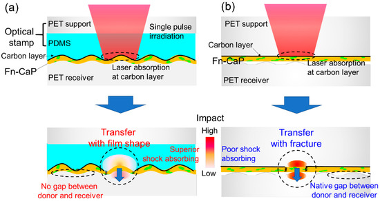
Figure 4.
A model for the Fn-CaP film transfer by (a) LIFTOP and (b) LIFT. A single nanosecond laser pulse was irradiated on (a) the Fn-CaP/C/PDMS/PET donor sample through the carbon-coated optical stamp or (b) the Fn-CaP/C/PET donor sample through the carbon-coated PET support, leading to strong laser absorption at the carbon sacrificial layer and the subsequent donor film transfer.
The present LIFTOP process is based on single-shot irradiation and absorption of a low-energy nanosecond laser pulse in the carbon sacrificial layer in the Fn-CaP/C/PDMS/PET donor sample, which is basically the same as the LIFT process in our previous report [16]. In our previous work [16], the CHO-K1 cell culture experiments revealed the better cytocompatibility of Fn-apatite microchips prepared on a PDMS receiver substrate by LIFT using the C/PET support (with a carbon sacrificial layer), compared to apatite microchips without Fn. This result suggests that the Fn protein in the Fn-apatite donor film retained its cell adhesion activity even after the LIFT process. In the present LIFTOP process using the C/PDMS/PET support, the optically transparent PDMS layer should have no significant effect on laser-induced phenomena in the carbon sacrificial layer such as ablation and heat generation. Therefore, the LIFTOP process as well as the LIFT process is considered to be effective in the transfer of protein-immobilized CaP films without fatal protein inactivation. Anyway, further investigation on the effect of the LIFTOP process on the microchip properties, such as bioactivity, chemical composition (Ca/P ratio, Fn content, etc.), and crystallinity, will be proceeded in our future work.
3.4. Rapid and Area-Specific Printing of Fn-CaP Microchips onto Human Dentin Surface
Since the LIFTOP process made it possible to transfer the Fn-CaP film onto hard substrates such as PET, we applied this technique to transfer the Fn-CaP film onto human dentin substrates. Human dentin contains apatite as an inorganic component, which is 70%, in addition to collagen as an organic component. Although human dentin is softer than human enamel (Mohs hardness is 5–6), it is still harder than PDMS. Thus, we employed the LIFTOP process for Fn-CaP printing onto a human dentin surface.
Figure 5a shows a schematic image of the LIFTOP process for the transfer of the Fn-CaP film to the human dentin substrate (same as Figure 3a except for the receiver substrate). Figure 5b,c shows confocal laser scanning microscopic images of the Fn-CaP/C/PDMS/PET donor sample after laser irradiation and of the Fn-CaP microchips printed on the human dentin substrate, respectively. The pulse energy was set at 160 μJ. In Figure 5b, it can be observed that the Fn-CaP donor film was removed at the laser irradiated spots with an average diameter of approximately 80 μm. The Fn-CaP film thickness was estimated to be approximately 500 nm from the hole depth. Corresponding to the ejection of the donor film, the Fn-CaP microchips were successfully printed on the dentin surface with an average diameter of approximately 80 μm, as shown in Figure 5c. This shows that LIFTOP is applicable to the additive micropatterning of the brittle Fn-CaP film on the human dentin substrate, and that it would be useful for the tooth surface functionalization. Figure 5d shows the laser pulse energy dependence of the average hole diameter on the donor sample after laser irradiation (red open circles) and the average diameter of the Fn-CaP microchips printed on the human dentin substrate (blue solid circles). The transfer threshold was between 80 and 100 μJ, which was the same with the Fn-apatite donor film formed on the C/PET support, as reported in our previous work [16]. The ablation threshold of the carbon film is reported to be below 50 μJ [16], which is much lower than the transfer threshold in the present LIFTOP process. This difference might correspond to the energy required for cutting and ejecting the film. Both the hole and the transferred microchip sizes increased with the pulse energy.
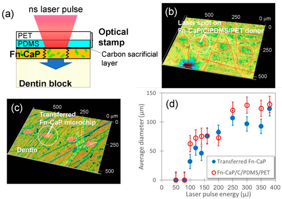
Figure 5.
(a) Schematic image of the LIFTOP process for the human dentin substrate. (b,c) Confocal laser scanning microscopic images of (b) the Fn-CaP/C/PDMS/PET donor sample after LIFTOP and (c) the Fn-CaP microchips transferred on the human dentin substrate. (d) Laser pulse energy dependence of the diameters (average ± standard deviation) of the holes on the donor sample after LIFTOP (red open circles) and of the transferred Fn-CaP microchips on the human dentin substrate (blue closed circles).
3.5. Surface and Interface Observation of the Fn-CaP Microchips Printed on the Dentin Substrate
For a closer look at the surface and interface of the Fn-CaP microchips printed onto the dentin substrate, high-magnification SEM observation was performed. Figure 6 shows SEM images of the surfaces of the Fn-CaP microchips printed on the dentin substrate using LIFTOP. Although a few straight cracks were observed on the microchip surfaces in Figure 6a, most of the microchips maintained a filmy shape. From the magnified image in Figure 6b, the dentin substrate had a non-flat surface with a number of scratches due to prior surface polishing. It should be mentioned that the surface of the Fn-CaP microchip was dented along the scratches on the dentin. In Figure 6c, the dents on the microchip along the scratches on the dentin can be seen more clearly.
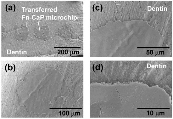
Figure 6.
(a–d) SEM images of the Fn-CaP microchips transferred by LIFTOP on the dentin substrate.
Finally, the interface between the transferred Fn-CaP microchip and the dentin substrate was evaluated by SEM using the cross-sectional sample prepared through the FIB processing. The SEM images in Figure 7a–c show the dentin substrate with the Fn-CaP microchip, (a) before, (b) during, and (c) after the FIB processing. A part of the area surrounded by the white dotted line in (b) was sliced with FIB. The sliced part was taken out for cross-sectional observation, as shown in (c). The cross-sectional SEM image of the sample is shown in Figure 7d. A white-colored top layer is a tungsten coat, which was applied onto the substrate in the FIB processing for surface protection. There were, for the most part, no obvious gaps at the interface between the microchip and the dentin substrate, suggesting good contact between them. Figure 7e shows a higher-magnification SEM image of the area surrounded by the white dotted line in (d), which confirms the presence of submicron pores in the film (near the interface) as well as the good contact at the film–dentin interface. These pores are related to the porous structure of the original donor film in Figure 2b. Thus, a donor film with a smoother surface can possibly lead to the formation of a smoother poreless interface.
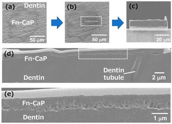
Figure 7.
(a–c) SEM images of the dentin substrate with the Fn-CaP microchip, (a) before, (b) during, and (c) after the focused ion beam (FIB) processing. A part of the area surrounded by the white dotted line in (b) was sliced with a FIB. The sliced part was taken out for cross-sectional observation, as shown in (c). (d) The cross-sectional SEM image of the Fn-CaP microchip on the dentin substrate. (e) High-magnification SEM image of the area surrounded by the white dotted line in (d).
3.6. Potential of the LIFTOP Process
Biofunctional CaP coating would be useful for the surface functionalization of human tissues as well as medical devices, such as orthopedic and dental implants. Among conventional CaP coating processes, biomimetic processes have the advantage of mild coating conditions and, hence, can produce CaP coatings loaded with biofunctional substances including proteins, trace elements, antibacterial agents, nucleic acids, etc. [30,32]. However, conventional biomimetic processes generally lack area-specific coating capability and require a long processing time (at least a few hours), except for a few recent techniques [31,33]. In the present LIFTOP process, printing of the Fn-CaP microchips was completed within only a few seconds for an area of approximately 10 mm2. Further, the printed region was finely confined to the laser irradiated spot. That is, the LIFTOP process is effective in the rapid and area-specific printing of Fn-CaP. As a substrate for Fn-CaP printing, not only soft and hard polymers but also human dentin was usable as demonstrated in this study. That is, it would be possible to modify and functionalize a human tooth surface through the biofunctional Fn-CaP printing by the LIFTOP process. It should be emphasized that the printing position, area, and pattern can be easily modified and adjusted by patterning and/or scanning of laser beam. Moreover, the CaP donor film can contain not only Fn but also many other biofunctional substances as described above. Therefore, by selecting an appropriate biofunctional substance for immobilization in the CaP donor film, the final product (CaP microchips) by the LIFTOP process can potentially be tailored to exhibit biological properties demanded for each application. Taken together, the LIFTOP process has potential as a new practical method for the surface-functionalization of medical devices and human tissues, although further process refinement along with in vitro and in vivo studies is needed.
4. Conclusions
In this study, we developed a novel LIFT process using the PDMS-coated transparent support (optical stamp), which we call LIFT with optical stamp (LIFTOP), in order to transfer brittle materials even onto hard receiver substrates without fractures. A cell adhesion protein fibronectin-immobilized calcium phosphate (Fn-CaP) film was prepared on the optical stamp using the biomimetic process. By the LIFTOP process, the Fn-CaP film was transferred from the optical stamp and the Fn-CaP microchips were successfully printed onto the PET and human dentin receiver substrates. Further, cross-sectional SEM observation revealed good attachment of the transferred Fn-CaP microchip onto the dentin surface without obvious gaps for the most part. The LIFTOP process for the rapid and area-specific printing of Fn-CaP would be useful for the surface functionalization of medical devices and human tissues.
Author Contributions
Conceptualization, A.N.; methodology, A.N. and A.O.; investigation, A.N. and A.O.; resources, A.N., A.O., and H.M.; data curation, A.N.; writing—original draft preparation, A.N.; writing—review and editing, A.O. and H.M.; visualization, A.N.; project administration, A.N.; funding acquisition, A.N. All authors have read and agreed to the published version of the manuscript.
Funding
This research was partially funded by KAKENHI JP 19H02635 from Japan Society for the Promotion of Science (JSPS) and grant no. AF-2017202 from the Amada Foundation.
Acknowledgments
The authors thank R. Kurosaki for SEM observation, N. Yoshizawa, and N. Saito of National Institute of Advanced Industrial Science and Technology (AIST) for FIB-SEM analyses and I. Sakamaki and T. Kameyama for sample preparation.
Conflicts of Interest
The authors declare no conflict of interest.
References
- Bohandy, J.; Kim, B.F.; Adrian, F.J. Metal deposition from a supported metal film using an excimer laser. J. Appl. Phys. 1986, 60, 1538–1539. [Google Scholar] [CrossRef]
- Feinaeugle, M.; Pohl, R.; Bor, T.; Vaneker, T.; Römer, G. Printing of complex free-standing microstructures via laser-induced forward transfer (LIFT) of pure metal thin films. Addit. Manufact. 2018, 24, 391–399. [Google Scholar] [CrossRef]
- Zenou, M.; Sa’ar, A.; Kotler, Z. Supersonic laser-induced jetting of aluminum micro-droplets. Appl. Phys. Lett. 2015, 106, 181905. [Google Scholar] [CrossRef]
- Banks, D.P.; Grivas, C.; Mills, J.D.; Eason, R.W.; Zergioti, I. Nanodroplets deposited in microarrays by femtosecond Ti:sapphire laser-induced forward transfer. Appl. Phys. Lett. 2006, 89, 193107. [Google Scholar] [CrossRef]
- Nakata, Y.; Hayashi, E.; Tsubakimoto, K.; Miyanaga, N.; Narazaki, A.; Shoji, T.; Tsuboi, Y. Nanodot array deposition via single shot laser interference pattern using laser-induced forward transfer. Int. J. Extrem. Manufact. 2020, 2, 025101. [Google Scholar] [CrossRef]
- Narazaki, A.; Sato, T.; Kurosaki, R.; Kawaguchi, Y.; Niino, H. Nano- and microdot array formation of FeSi2 by nanosecond excimer laser-induced forward transfer. Appl. Phys. Express 2008, 1, 057001. [Google Scholar] [CrossRef]
- Baum, M.; Kim, H.; Alexeev, I.; Piqué, A.; Schmidt, M. Generation of transparent conductive electrodes by laser consolidation of LIFT printed ITO nanoparticle layers. Appl. Phys. A 2013, 111, 799–805. [Google Scholar] [CrossRef]
- Narazaki, A.; Kurosaki, R.; Sato, T.; Niino, H. On-demand patterning of indium tin oxide microdots by laser-induced dot transfer. Appl. Phys. Express 2013, 6, 092601. [Google Scholar] [CrossRef]
- Narazaki, A.; Kurosaki, R.; Sato, T.; Niino, H. On-demand deposition of functional oxide microdots by double-pulse laser-induced dot transfer. J. Laser Micro/Nanoeng. 2014, 9, 10–14. [Google Scholar] [CrossRef]
- Breckenfeld, E.; Kim, H.; Auyeung, R.C.Y.; Charipar, N.; Serra, P.; Piqué, A. Laser-induced forward transfer of silver nanopaste for microwave interconnects. Appl. Surf. Sci. 2015, 331, 254–261. [Google Scholar] [CrossRef]
- Piqué, A.; Auyeung, R.C.Y.; Kim, H.; Charipar, N.; Mathews, S.A. Laser 3D micro-manufacturing. J. Phys. D Appl. Phys. 2016, 49, 223001. [Google Scholar] [CrossRef]
- Tsakona, D.; Theodorakos, I.; Kalaitzis, A.; Zergioti, I. Investigation on high speed laser printing of silver nanoparticle inks on flexible substrates. Appl. Surf. Sci. 2020, 513, 145912. [Google Scholar] [CrossRef]
- Smits, E.C.P.; Walter, A.; de Leeuw, D.M.; Asadi, K. Laser induced forward transfer of graphene. Appl. Phys. Lett. 2017, 111, 173101. [Google Scholar] [CrossRef]
- Sorkio, A.; Koch, L.; Koivusalo, L.; Reiwick, A.; Miettinen, S.; Chichkov, B.; Skottman, H. Human stem cell based corneal tissue mimicking structures using laser-assisted 3D bioprinting and functional bioinks. Biomaterials 2018, 171, 57–71. [Google Scholar] [CrossRef] [PubMed]
- Leva, V.; Chatzipetrou, M.; Alexopoulos, L.; Tzeranis, D.S.; Zergioti, I. Direct laser printing of liver cells on porous collagen scaffolds. J. Laser Micro/Nano-Eng. 2018, 13, 234–237. [Google Scholar]
- Narazaki, A.; Oyane, A.; Komuro, S.; Kurosaki, R.; Kameyama, T.; Sakamaki, I.; Araki, H.; Miyaji, H. Bioactive micropatterning of apatite immobilizing cell adhesion protein by laser-induced forward transfer with a shock absorber. Opt. Mater. Express 2019, 9, 2807–2816. [Google Scholar] [CrossRef]
- Auyeung, R.C.Y.; Kim, H.; Mathews, S.; Piqué, A. Laser forward transfer using structured light. Opt. Express 2015, 23, 422–430. [Google Scholar] [CrossRef]
- Turkoz, E.; Perazzo, A.; Deike, L.; Stone, H.A.; Arnold, C.B. Deposition-on-contact regime and the effect of donor-acceptor distance during laser-induced forward transfer of viscoelastic liquids. Opt. Mater. Express 2019, 9, 2738–2747. [Google Scholar] [CrossRef]
- Shugaev, M.V.; Bulgakova, N.M. Thermodynamic and stress analysis of laser-induced forward transfer of metals. Appl. Phys. A 2010, 101, 103–109. [Google Scholar] [CrossRef]
- Röder, T.C.; Köhler, J.R. Physical model for the laser induced forward transfer process. Appl. Phys. Lett. 2012, 100, 071603. [Google Scholar] [CrossRef]
- Pohl, R.; Visser, C.W.; Römer, G.R.B.E.; Sun, C.; Huis in’t Veld, A.J.; Lohse, D. Imaging of the ejection process of nanosecond laser-induced forward transfer of gold. J. Laser Micro/Nanoeng. 2015, 10, 154–157. [Google Scholar] [CrossRef]
- Pohl, R.; Visser, C.W.; Römer, G.R.B.E.; Lohse, D.; Sun, C.; Huisin’t Veld, B. Ejection regimes in picosecond laser-induced forward transfer of metals. Phys. Rev. Appl. 2015, 3, 024001. [Google Scholar] [CrossRef]
- Habraken, W.; Habibovic, P.; Epple, M.; Bohner, M. Calcium phosphates in biomedical applications: Materials for the future? Mater. Today 2016, 19, 69–87. [Google Scholar] [CrossRef]
- Das, P.; Jana, N.R. Length-controlled synthesis of calcium phosphate nanorod and nanowire and application in intracellular protein delivery. ACS Appl. Mater. Interfaces 2016, 8, 8710–8720. [Google Scholar] [CrossRef] [PubMed]
- Cai, Z.; Wang, X.; Zhang, Z.; Han, Y.; Luo, J.; Huang, M.; Zhang, B.; Hou, Y. Large-scale and fast synthesis of nano-hydroxyapatite powder by a microwave-hydrothermal method. RCS Adv. 2019, 9, 13623–13630. [Google Scholar] [CrossRef]
- Dorozhkin, S.V. Nanodimensional and nanocrystalline apatites and other calcium orthophosphates in biomedical engineering, biology and medicine. Materials 2009, 2, 1975–2045. [Google Scholar] [CrossRef]
- García-sanz, F.J.; Mayor, M.B.; Arias, J.L.; Pou, J.; Leon, B.; Pérez-amor, M. Hydroxyapatite coatings: A comparative study between plasma-spray and pulsed laser deposition techniques. J. Mater. Sci. Mater. Med. 1997, 8, 861–865. [Google Scholar] [CrossRef]
- Blinda, O.; Kleinb, L.H.; Daileya, B.; Jordan, L. Characterization of hydroxyapatite films obtained by pulsed-laser deposition on Ti and Ti-6AL-4v substrates. Dent. Mater. 2005, 21, 1017–1024. [Google Scholar] [CrossRef]
- Rau, J.V.; Cacciotti, I.; Laureti, S.; Fosca, M.; Varvaro, G.; Latini, A. Bioactive, nanostructured Si-substituted hydroxyapatite coatings on titanium prepared by pulsed laser deposition. J. Biomed. Mater. Res. 2015, 103, 1621–1631. [Google Scholar] [CrossRef]
- Oyane, A.; Wang, X.P.; Sogo, Y.; Ito, A.; Tsurushima, H. Calcium phosphate composite layers for surface-mediated gene transfer. Acta Biomater. 2012, 8, 2034–2046. [Google Scholar] [CrossRef]
- Oyane, A.; Sakamaki, I.; Shimizu, Y.; Kawaguchi, K.; Koshizaki, N. Liquid-phase laser process for simple and area-specific calcium phosphate coating. J. Biomed. Mater. Res. 2012, 100A, 2573–2580. [Google Scholar] [CrossRef] [PubMed]
- Oyane, A.; Murayama, M.; Yamazaki, A.; Sogo, Y.; Ito, A.; Tsurushima, H. Fibronectin–DNA–apatite composite layer for highly efficient and area-specific gene transfer. J. Biomed. Mater. Res. 2010, 92A, 1038–1047. [Google Scholar] [CrossRef] [PubMed]
- Oyane, A.; Sakamaki, I.; Koga, K.; Nakamura, M.; Shitomi, K.; Miyaji, H. Antibacterial tooth surface created by laser-assisted pseudo-biomineralization in a supersaturated solution. Mater. Sci. Eng. 2020, 116, 111170. [Google Scholar] [CrossRef] [PubMed]
Publisher’s Note: MDPI stays neutral with regard to jurisdictional claims in published maps and institutional affiliations. |
© 2020 by the authors. Licensee MDPI, Basel, Switzerland. This article is an open access article distributed under the terms and conditions of the Creative Commons Attribution (CC BY) license (http://creativecommons.org/licenses/by/4.0/).