Abstract
The objective of this study is to design a therapeutic method combining a portable high intensity focused ultrasound (HIFU) design which is suitable for the laboratory environment and a tailored integrated photo-acoustic imaging (PAI) system for monitoring thermal treatment. The electrical HIFU design is fabricated with changeable operating frequency and justified output power for resonating with different kinds of commercial transducers. The system’s control interface is built based on a touch screen to create a companionable interaction for users. The embedded fuzzy logic controller using the thermal input from the thermocouple sensor precisely drives the target temperature during HIFU exposure to achieve the expectedly coagulating results. The PAI system with 532-nm laser excitation is also integrated to define the affected region before and after HIFU treatment. The proposed fuzzy controller-integrated HIFU setup compatible with the PAI system is a feasible instrument in thermal therapy for ex vivo artificial tumors management.
1. Introduction
Among surgical techniques for treating solid tumors, high intensity focused ultrasound (HIFU) is a promising noninvasive approach to destroy cancerous cells [1,2]. Unlike conventional radiation therapy, HIFU can kill diseased tissues without causing collateral damage to normal surroundings [3,4,5,6]. The high-power ultrasound waves generated from the HIFU transducer are focused on a specific region to induce thermal necrosis at the abnormal tissue position. The commercial electrical HIFU system is used to drive the HIFU transducer output power for the sake of particular applications.
With a typical electric HIFU framework, a low power waveform signal created by the commercial waveform generator is transmitted to the RF power amplifier which intensifies the waveform before applying it to the HIFU transducer through an impedance matching network [7,8,9,10]. The operation frequency of the system is modified from 1 to 5 MHz, and it is able to deliver power up to hundreds of watts. Unfortunately, this kind of arrangement is beyond several laboratories’ budgets [11]. It requires a lot of financial effort of certain lab-based researchers to conduct a small experiment. Thus, the motivation for this study was to create a compact, feasible system that is more cost-effective than alternative solutions, thus prompting widespread applications of this technology.
In thermal therapy, overheating leads to unexpected severe denaturation of tissues, leading to organ damage; thus, temperature control is critical for HIFU treatment [12,13,14]. The recommended temperature of 60 °C needs to be maintained at the focal point with sufficient time to coagulate the tumor and be harmless to the tissue [15]. The thermocouple sensor is a possible solution for thermal monitoring due to its primary benefit of rapid response time [16,17,18]. Several prior studies have discussed the feasibility of fuzzy logic algorithm to weather uncertain objectives like the temperature [19,20,21]. With feedback from the thermocouple, a fuzzy controller is applied to the system to manipulate the target temperature in real-time during HIFU treatment.
Additionally, for effective monitoring of the experimental study, a reliable imaging-guided method is integrated. For clinical applications, there are two common types of image guidance: ultrasound (US) [9,10,22,23] or magnetic resonance imaging (MRI) [14,24,25,26]. Guided imaging is useful for preliminary diagnosis, treatment planning, and real-time response monitoring. However, a large space required for setup and the costly expense charged for the system are the downsides of these techniques. On the contrary, in the laboratory environment, another option called photoacoustic imaging (PAI) is also used to meet the HIFU monitoring requirements. Factors influencing a successful HIFU cancer therapy are: (i) precise positioning of the tumor region before treatment, (ii) the HIFU beam is focused with sufficient spatial accuracy and selectivity to the region of interest (ROI), (iii) the tissue status is monitored during treatment, and (iv) post-treatment evaluation of the tissue ablation’s size. PAI provides the opportunity to handle all four requirements [27,28,29,30]. The vascular increase in the tumor area leads to photoacoustic (PA) image contrast that can be utilized to locate the tumor. Once defined, the HIFU beam is required to accurately deliver acoustic power so that it can locally destroy the tumor without damaging the normal surrounding tissues.
This study proposes the integration of the fuzzy controller supporting the HIFU system with PAI design. A thermal methodology using the combined structure was constructed to administer treatment for artificial chicken breast tumors. The process has been described in detail, and the subsequent discussion is aimed to overcome remaining limitations to be more feasible for clinical applications in the future.
2. Materials and Methods
2.1. Electrical Design of HIFU System
The first feature of this study was designing a compact electrical circuit to drive the high-power transducer. A single element piezoelectric HIFU transducer (H-148, Sonic Concept, Woodinville, WA, USA) with the electrical power up to 400 W was chosen for the experiment. Several essentially designed parameters for the electrical HIFU system were defined depending on the manufacturer’s specification of the transducer. The output signal frequency was fixed at 2 MHz to resonate with the chosen transducer, thus resulting in the highest ultrasonic power. The dual-channel MOSFET switching method was the primary principle to double the acoustic power of the transducer by creating positive-negative voltage output signals [31,32,33].
To minimize the overall size of HIFU design, the electrical system was divided into two individual printed circuit boards (PCB)—a power and control board as shown in Figure 1a. The 3D design of the HIFU system with the H-148 commercial transducer is also denoted in Figure 1b. There are several blocks belonging to the control, with the 32-bit microcontroller (PIC32MX795F512L, Microchip Technology Inc., Austin, TX, USA) acting as the core of the whole system. In order to measure the temperature at the focused point precisely, the 1.1-mm diameter thermocouple probe along with the miniature K-Type panel socket (R-FMTC-K-FF, RS Pro, Kwai Chung, Hong Kong, China) was used with the accuracy of ±1 °C. The temperature at the thermocouple tip was converted to the electrical signal by 24-bit ADC (AD7739, Analog Device, Northwood, MA, USA) before being transmitted to the microcontroller every 0.5 s through SPI communication. The acquired target temperature was subsequently transferred to the PC through a COM port using USB UART IC (FT232RL, FTDI Ltd., Glasgow, UK) every 1 s, which was set by a registered timer. The waveform generation block included a resistor set oscillator (LTC1799, Analog Device, Northwood, MA, USA) used to create the low power 5 V-squared signal with a frequency range from 1 kHz to 33 MHz. This operating frequency could be modified by a single digital potentiometer (MCP41100 Microchip Technology Inc., Austin, TX, USA) whose resistance could be programmable by the microcontroller via SPI interface. For setting the output frequency of the electrical system, the value of the corresponding resistance was calculated by the following equation:
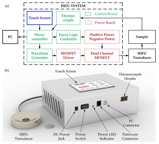
Figure 1.
HIFU system: (a) schematic diagram (b) 3D design.
As mentioned above, the digital potentiometer needed to be changed to the resistance of 50 kΩ to form the frequency of 2 MHz, and the microcontroller was programmed to transmit an amount of the bit required. On the power board, a 2-MHz squared wave input signal with the duty cycle 50%, which coincides with the 5 V TTL standard, was created by waveform generation block, then amplified by a 5 V MOSFET driver (EL7158ISZ, Renesas Inc., Milpitas, CA, USA) to obtain the high power 5 V signal. The output signal from the previous stage was then further amplified by the 12-V MOSFET driver EL7158ISZ to generate the 12 V high power signal which is used to excite the switching event of the MOSFET.
The 100V MOSFETs (Si4590DY, Vishay Intertechnology, Malvern, PA, USA) in this model were the dual-type, including NMOS and PMOS as two switching channels. The 12 V squared waveform signal that came from the MOSFET driver was the single input for both of them. Fundamentally, if V_gs > 0, NMOSFET was activated; meanwhile, the PMOSFET was enabled if V_gs < 0. When MOSFET was in ON-state, the current from the power supply was supplied to the input pins of MOSFET ICs, leading to the generation of high-power output drive signal for HIFU transducer. In order to create a bipolar squared wave (both positive and negative side) from the 12 V 2 MHz input signal to trigger HIFU transducer to launch the maximum acoustic power (at peak-to-peak voltage), the NMOS and PMOS channels needed to be used simultaneously. Therefore, the power supply was converted to both positive and negative voltage to apply on the two sides of MOSFETs. The parallel structure of MOSFETs’ output pins granting a very low output impedance which allows almost all the energy from the power source to the HIFU transducer and achieves the maximum acoustic pressure without using the impedance matching network [34,35].
A 5-inch LCD touch screen (NX8048T050, Nextion, Shenzhen, GD, China) was used to display a friendly interface (Figure 2) on the surface of the product, where the user could interact with the system through the built-in UART communication. The operating frequency was set at 2 MHz as a default value; it could also be changed from 0.1 to 5 MHz, at 0.1-MHz increments. The electrical output power was divided into six levels depending on the output signals, with the highest one being 50 W. In the manual mode, when the HIFU system was activated by pressing the button “Start”, the timer would start counting until the system was forced to stop. The user was able to set the working time in the auto mode by increasing the timer, with a maximum period of 300 s. The acoustic signals were continuously generated until the preset time period elapsed. In case of recording the temperature data during the HIFU experiment, the user could press the “Record” button before the exposure and press one more time to stop the data flow whenever needed.
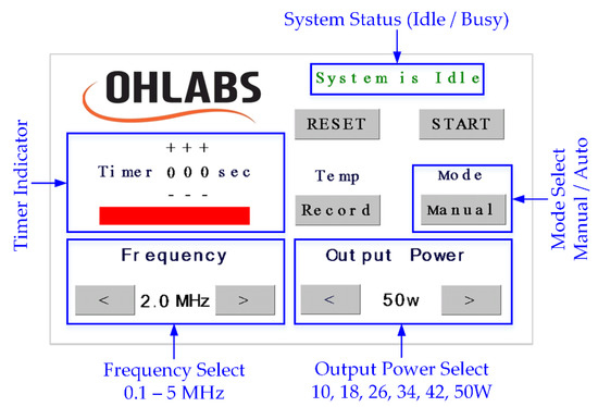
Figure 2.
HIFU system touch screen interface.
2.2. Characterization of HIFU System
The evaluation of the HIFU system was carried out in terms of electrical output voltage before applying for the HIFU transducer. An oscilloscope (InfiniiVision MSOX2024A, Keysight Technologies, Chandler, AZ, USA) was used to pick up the output signals from the HIFU system at a sampling rate of 2 G/s. The acoustic pressure signals generated from the HIFU transducer were captured by a hydrophone (0.2-mm needle, Precision Acoustics Ltd., Dorchester, UK) before being displayed on the oscilloscope (Figure 3a). The acoustic pressure was calculated as the equation below during the HIFU activation [36]:
where is the acoustic pressure waveform (W/cm2), P is the measured hydrophone voltage (Pa), is the water density (997 kg/m3), and is the sound velocity (1480 m/s) in the water at 20 °C. To protect the needle hydrophone from high power pressure during the measurements, only a low voltage level from the HIFU circuit (±9 V) was tested. A manual, three-axis stage with a spatial resolution of 0.1 μm drives the hydrophone to detect acoustic signals to attain corresponding pressure values.
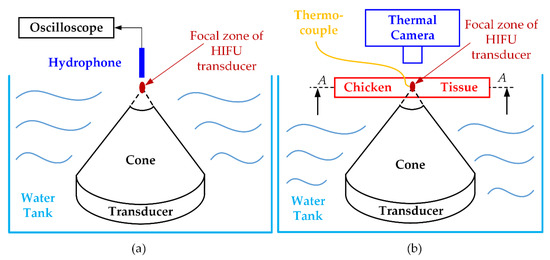
Figure 3.
Ex vivo experiment for validating HIFU system performance: (a) acoustic pressure measurement (b) maximum temperature achievement and fuzzy logic controller testing.
To illustrate the applicability of a certain HIFU system in the experimental environment, the thermal effect of this system was also considered, or, in other words, the ability to heat the target sample to a certain temperature was firmly confirmed. The chicken breast tissues (40 × 40 × 20 mm3) were used to check the maximum temperature of our HIFU system. Figure 3b indicates how to set up the HIFU ex vivo experiment. The HIFU transducer was delicately calibrated to focus the beam at the 2 mm away from the top surface of the chicken breast tissue. The HIFU transducer and half of the chicken breast tissue were laid underwater during the experiment. The thermocouple was attached under the surface of the tissue and 1 mm away from the treatment axis to avoid potential acoustic absorption caused by the thermocouple. In addition, to observe the maximum temperature and the temperature distribution during the experiment with the HIFU system, the IR thermal camera (FLIR i5, FLIR Systems Inc., Portland, OR, USA) was used to capture the surface (A-A) temperature image every 10 s interval. The HIFU circuit was turned on until the focused area reached the highest temperature, and thermal data was collected from two different sources.
2.3. Ex Vivo Experiment with Fuzzy Logic Control
In order to maintain the target sample at a constant temperature during the HIFU treatment to destroy the tumor, a fuzzy logic controller was applied to the microcontroller. The range of temperature errors was acceptable at around ±4 °C; therefore, a “good enough” solution like the fuzzy controller fit this requirement. With a classic feedback scheme, the exact temperature provided by the thermocouple must then be converted into the fuzzy value that comprises the variables of the predecessor in the rule base [37]. Likewise, the fuzzy values inferred from the rules must be transformed into commands for use in the voltage regulator. A general fuzzy system was introduced to control the target temperature as shown in Figure 4; the fuzzy set, fuzzy state, and the fuzzy rule are demonstrated in Table 1.
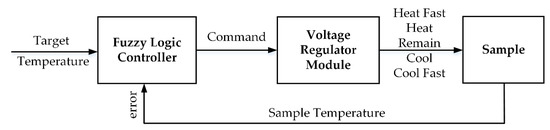
Figure 4.
Proposed Fuzzy Logic Control System.

Table 1.
Fuzzy set, fuzzy state and fuzzy rule of the proposed control system.
Following the datasheet of the step-down switching regulator (LT1074, Analog Devices, Northwood, MA, USA), both positive and negative output voltage could be adjusted by changing the resistance between switch voltage and feedback pins. By default, the output voltage was set at ±21 V with the value of resistors at 18.8 kΩ which is connected to a parallel group of fixed potentiometers. Each individual could be activated to change the total resistance and create the required bipolar output voltage. The output voltages ±18 V, ±15 V, ±12 V, ±9 V, ±6 V were chosen to be the outputs of the fuzzy logic controller corresponding to “heat fast”, “heat”, “remain”, “cool”, or “cool fast” the target sample.
The chicken breast tissues were also used to check the degree of thermal damage of the proposed HIFU design. The experimental setup was mostly the same as in the last section but this time, the focal point of the transducer would be justified on the middle plane of the tissue. The experiment duration was stretched to various periods of times (60, 120, 180, 240, and 300 s) for evaluating the extent of thermal coagulation. After the treatment, each sample was removed, and a cross-section was made in the longitudinal direction at the treated area. Later, every sample was captured by a digital camera, and the region of treatment was defined and consciously calculated five times (N = 5) in terms of the area in ImageJ (ImageJ 1.53a, National Institute of the Health, Bethesda, MD, USA).
2.4. Ex Vivo Experiment with PAI System
Before the experiments, bovine hemoglobin (Hb) (H3760, Sigma-Aldrich, MO, USA), and gelatin (G-2500, Sigma-Aldrich, MO, USA) were used to mimic breast tumors [38]. First, 10 mL saline was blended with 1 g of Hb powder and stirred at 60 °C for 15 min. Then, 2% gelatin was poured into the completely dissolved Hb powder and stirred again in 10 min to achieve a uniform Hb distribution. Next, to remove the accumulated bubbles produced in the mixing process, the prepared solution was placed into a vacuum machine (PVH-PO-27, Labpartners, Cincinnati, OH, USA). Additionally, chicken breast tissues with the same dimensions as described in the previous section were also prepared. Then, a cylindrical part in the middle of tissues with an 8-mm circular diameter was removed and placed on a petri dish. To create the tumor phantom, the Hb solutions were injected into the detached cylindrical tissues until the sample color turned black. Then, the petri dish was stored in a refrigerator at 0 °C for 5 min to freeze the sample. Afterward, the developed artificial tumor was inserted back to the hole left after rejecting the tissue earlier. Finally, the whole sample was stored again in the refrigerator for 10 min at 0 °C to prepare it for the experiment. With this procedure, the tumor and the normal tissue region are completely separated so that they are visually distinguished by the PAI system and it is much easier while conducting ex vivo experiments.
For tissue treatment and monitoring, a customized PAI module was constructed and integrated with the HIFU system. The entire configuration of the ex-vivo experiment, including HIFU and PAI system, is described in Figure 5a. The laser source used a pumping Q-switched diode (SPOT-10-100-532, Elforlight, Daventry, UK) operating at 5 kHz repetition rate. The 532-nm laser output wavelength was generated to scan the artificial tumor including Hb particles [39]. The laser beam was coupled to a 2-m single-mode fiber (P3-460B-FC-2, Elforlight, Daventry, UK) through a fiber coupler and a half-wave plate. The output laser of the fiber with the intensity energy under 13.3 mJ/cm2 was led in a PAI probe before irradiating the tissue sample as demonstrated in Figure 5c. The self-made acrylic PAI probe was designed and delicately fabricated by the milling machine. Figure 5b illustrates the structure of the PAI probe consisting of a focusing lens, an aluminum layer which reflects the laser beam to the sample. PA signals induced under the laser irradiation were detected using a flat single element 75-MHz ultrasound transducer (V2025, Olympus, Norfolk, VA, USA). A linear positioning in the z-axis direction was justified to calibrate the focal beam of the transducer to attain the maximum PA signal amplitude. A 2D linear stage (x-, y-axis) with 10 μm spatial resolution synchronized with the laser trigger was also used to scan the sample for constructing a 14 × 14 mm2 2D image. The received PA signals were filtered and amplified by two serially connected low-noise preamplifiers (ZFL-500LN, Mini-Circuit, Brooklyn, NY, USA) and finally caught by a high-speed digitizer (NI PXI-5124, National Instruments, Austin, TX, USA). The raw data were directly processed using Labview (Labview 2014, National Instruments, Austin, TX, USA) to reconstruct the 2D PA image. The ROI of PA images and 3D structure according to the color intensity of the treated area was also reconstructed in ImageJ. The photoacoustic amplitudes of the thermally denatured areas were also measured five times (N = 5) by using ImageJ.
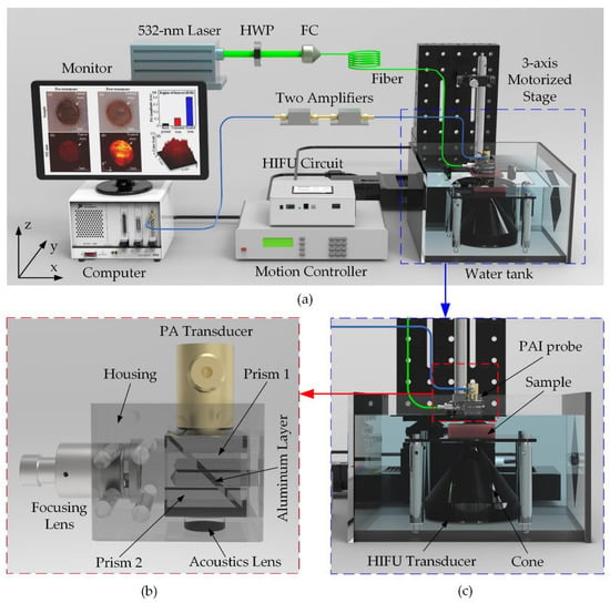
Figure 5.
Ex vivo HIFU experiment integrated with PAI system for artificial breast tumors treatment (a) System schematic diagram. HWP: Half-wave plate; FC: Fiber Coupler (b) Self-made PAI probe (c) Close-up of the blue-dash operating region.
2.5. Statistical Analysis
The statistical analysis, Kruskal Wallis as a nonparametric method, represents significant p < 0.05.
3. Results
3.1. Characteristic of HIFU System
Figure 6 exhibits the output waveforms created by the HIFU system at the various output voltages. The maximum output voltage the system could generate was ±21 V while the minimum was ±6 V. All the output waveforms had the center frequency of 2 MHz and the rising and falling time was equal to 30 ns. There was a moderate overshoot (20%) at the moment the waveforms changed from positive to negative and vice versa. The output signals with the symmetric positive and negative side square waveforms had been set at a 50% duty cycle before applying to the HIFU transducer. The acoustic pressure generated from the transducer was measured by the hydrophone at the focal point under the ±9 V voltage level. The peak-peak amplitude of the hydrophone signal was measured to 211 mV and the acoustic pressure was 105 mV in an electrical unit, which was equal to 2.3 MPa due to the 45 mV/MPa sensitivity. Using Equation (2) and several physical constants as described above, the acoustic pressure in this circumstance was 358 W/cm2. It is estimated that with the ±21 V output waveforms, the attainable acoustic pressure could be 5.4 MPa, and thus, a maximum acoustic intensity was possibly 1949 W/cm2 [40].
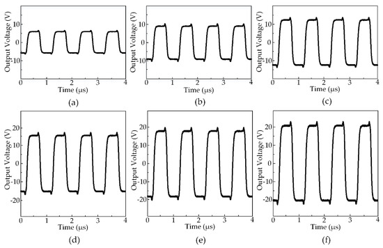
Figure 6.
The output waveforms from HIFU circuit measured at various voltage amplitudes at 50% duty cycle: (a) ±6 V (b) ±9 V (c) ±12 V (d) ±15 V (e) ±18 V (f) ±21 V.
The thermal ability of the HIFU system in the experiment with the chicken breast tissue was conducted to discover the maximum temperature at various output voltages. The temperature distribution at the surface of the tissue is shown in Figure 7a functioning by HIFU transducer at the biggest output voltage of ±21 V. The transducer beam formed a circular affected region on the surface of the tissue as the temperature rose with the time of exposure. There was a difference in the energy transmission between metal and tissue along with the thermocouple. Therefore, the circular treated region surrounding the thermal wire tip is slightly distorted. The tissue was heated to the highest temperature at 65 °C after 50 s of the treatment. The temperature data recorded by the thermocouple were presented in Figure 7b also confirmed this peak. It could be noticed that the temperature at the focused beam sharply increased in the first 20 s of the exposure time from 20.1 °C to 47.8 °C, then enhanced to 64.9 °C for the rest of the treatment. There is an insignificant deviation between the two ways of measuring then the data recorded from the thermocouple were rather reliable for the next experiment.
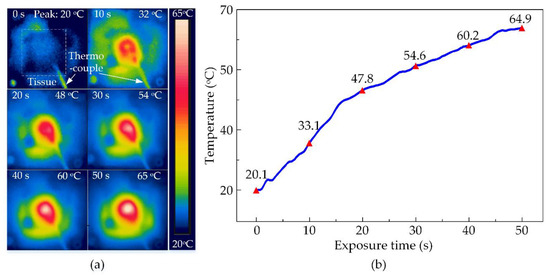
Figure 7.
The observed temperature of chicken breast tissues during HIFU treatment at ±21 V output voltage after 50 s (a) By thermal camera (b) By thermocouple.
3.2. Ex Vivo Experiment Results Using Fuzzy Logic Control
By the same method as described in the last section, the maximum temperatures obtained by other voltage outputs were also defined. These numbers are specified in the graph in Figure 8a with the minimum and maximum values at 55.9 ± 0.3 °C and 64.9 ± 0.2 °C corresponding to the output voltages of ±6 V and ±21 V. There are several different temperature peaks observed at 57.6 ± 0.3 °C, 59.9 ± 0.3 °C, 61.1 ± 0.2 °C, 63.0 ± 0.4 °C generated by ±9 V, ±12 V, ±15 V, ±18 V, respectively. Depending upon these peaks and the treatment target temperature, these output voltages acted as the outputs for the fuzzy logic control. Figure 8b shows the temperature observation graph in the entire 300 s of HIFU exposure in the ex vivo experiment using the fuzzy control system. The fuzzy controller helped the system to maintain a constant temperature in the target sample. Thus, the heated region is accurately located at the tumor model and avoid damaging the surrounding normal tissues during the HIFU treatment. The desired temperature was set to 60 °C and the system would actuate the HIFU transducer at the highest output voltage ±21 V to attain this value quickly. The tissue at the focal region under acoustic pressure was heated up to the target temperature within 40 s. Afterward, the target temperature remained at 60 °C with tolerable deviations of 4 °C during the exposure.
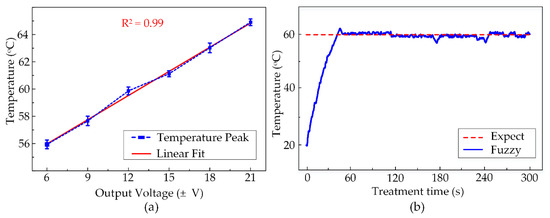
Figure 8.
(a) The temperature peaks reached by various output voltages (N = 5) (b) Temperature observation during 300 s of Fuzzy-control HIFU treatment.
The thermal coagulation cross-sectional images of chicken breast tissues at various exposure times are shown in Figure 9b. The opalescent regions representing the treated area were marked by the half-dash-dot line and visibly had ellipsoidal shapes due to the HIFU transducer focal beam. The smallest denaturation area was 13.5 ± 1.7 mm2 after 60 s of treatment then linearly increased to 31.7 ± 5.1 mm2, 46.5 ± 8.8 mm2, 70.9 ± 8.0 mm2 for 120 s, 180 s, and 240 s exposure time, respectively. The largest damaged region was 89.4 ± 9.1 mm2, produced after activating the HIFU system for 300 s, and it was almost seven times the size of the smallest one, as described in Figure 9a. The fuzzy-assisted HIFU system shaped a rising trend of the coagulation area as a linear fitting. Thus, the extension of the thermal denaturation of the tissue could be anticipated.
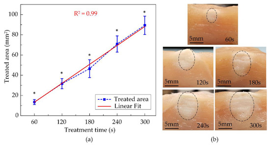
Figure 9.
The ex vivo experiment’s results using fuzzy logic control at various exposure times: (a) Treated areas (N = 5) (b) The cross-sectional images of treated tissues (* indicate significant difference at p < 0.05).
3.3. Ex Vivo HIFU Therapy Integrated with PAI System for the Artificial Breast Tumor Treatment
Figure 10 shows the top view of chicken breast tissue samples before and after HIFU treatment. Due to the artificial tumor preparation process, the region of the tumor could be distinguished from the normal tissue. The tumor area with its dark circular shape and pink surrounding tissues were discernible with the naked eyes, as shown in Figure 10a. The pretreatment PA image in Figure 10b also indicates the red colored area, representing the tumor region with the black background signifying normal surrounding tissues. Figure 10c shows the tissue sample after HIFU exposure; the tumor sample became opaque under the effect of hyperthermia. The PAI system was used to scan the sample one more time to differentiate the thermally treated region from the untreated tissues and is shown in Figure 10d. Using the ROI manager function of ImageJ software, the treated area was presented as a 3D image in terms of the color scale, as shown in Figure 10f. The higher the color scale, the stronger the PA signal resulting in a higher temperature. The HIFU transducer beam was focused in the center of the sample; therefore, the treated area was originally initiated here and then slowly spread to the surroundings. Figure 10e presents the significant increase of PA signal amplitude at the coagulated regions to 0.405 ± 0.005 while only 0.110 ± 0.001 for untreated tissue and 0.034 ± 0.002 for the background. Given considerable dissimilarities in image contrast, the acquired PA images were able to identify the situations of the breast tumor and the damaged tissue after the HIFU treatment.
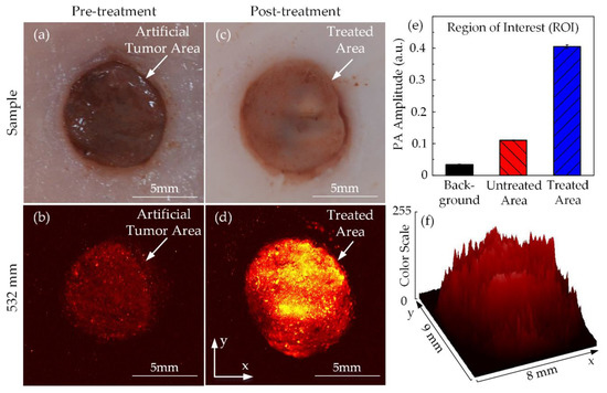
Figure 10.
PA images of tumor-injected chicken breast tissue in ex vivo HIFU treatment: tumor images (a) Before and (b) After treatment PA images (c) Before and (d) After treatment (e) PA amplitude (f) 3D image of the treated area according to the color scale.
4. Discussion
The study demonstrates a feasible thermal treatment for breast tumors with the combination of noninvasively fuzzy-integrated HIFU and PAI system. Compared to current methods, the proposed approach presented an affordable HIFU design for biomedical applications and a feasible imaging modality using laser and ultrasound to minimize the thermal injury during treatment.
The HIFU system consists of the function generator and the power amplifier was organized by the microcontroller in a compact design. The electrical technique with very low output impedance was employed to diminish the presence of the impedance matching circuit before applying for HIFU transducer. The changeable operating frequency and output power were highly suitable for numerous therapeutic applications. The indigenous control interface was also easily accessible to users.
A slight overshoot in the electrical output signals from the HIFU circuit due to the current surge during sudden MOSFET switching event (shown in Figure 6), acceptable for functioning fuzzy logic control. There were six different power levels produced by the HIFU system from 10 W to 50 W corresponding to the output voltage amplitude from ±6 V to ±21 V. With higher amplitude, the HIFU transducer generates the higher maximum target temperature. The strongest power delivered the most energetic acoustic pressure which enables temperature rising to a threshold of 64.9 ± 0.26 °C within 50 s (shown in Figure 7).
With temperature feedback from the thermocouple, the closed-loop fuzzy controller was implemented to maintain the 60 ± 4 °C temperature by modulating the output power during the treatment (Figure 8b). Figure 9 indicates the thermal effect of HIFU treatment in ex vivo chicken breast tissue, with the coagulation area linearly expanded with the exposure time. After 300 s of the HIFU treatment, the tissue coagulation area was 89.38 ± 9.1 mm2, which was substantially greater than those at 60 s (13.5 ± 2.5 mm2). The HIFU system with fuzzy logic control was able to maintain a constant target temperature. Present state-of-the-art studies only apply to a single preset temperature and need to be upgraded for a set of constant temperatures to tackle the unknown upcoming demands [41,42].
Previous studies have presented that contrast agent-assisted PAI was able to optically mimic the tumor [38]. The current study suggests a customized high-resolution PAI system guiding for artificial tumor treatment with the HIFU system. In Figure 10b, the tumor phantoms were sensitive with 532-mm laser wavelengths, so the PAI system could display a PA image of target regions even if the amplitude was not so strong. The appearance of the bright regions in Figure 10d, which represents the stronger PA signals, after the treatment process was probable evidence of the effectiveness of HIFU therapy in ex vivo experiments with phantom models. Depending on the significant differences among PA signals from both the untreated and treated regions, they were definitely separated, and the treated areas were effortlessly defined.
Despite the feasibility of the proposed fuzzy-controlled HIFU-PAI combined system; this study shows several limitations. Although the current HIFU system could deliver considerable acoustic intensity to affect target tissues, the electrical output signal should be refined to remove the overshoot phenomenon. The maximum acoustic intensity of H-148 HIFU transducer (46,161 W/cm2) could be achieved if the electrical system is capable of generating a high amplitude bi-polar squared output signal without noise. Another approach using different waveform principles such as harmonic reduced pulse-width modulation to maximize the output power of the single element transducer [43]. A whole new electrical design could be introduced to excite HIFU array transducer [44].
Moreover, even if the current temperature monitoring technique using the thermocouple has a real-time response advantage, this minimally invasive method is likely still restricted by clinical applications [45]. Additionally, the accuracy of this approach strongly varies from the relative position of the thermocouple tip and the focal beam of the HIFU transducer [46]. The single-point tracking of temperature is also a drawback since the observation of temperature in surrounding normal tissues during treatment is immensely important for clinical translation [47,48]. A noninvasive temperature monitoring method, such as using an embedded infrared camera, is a possible solution if the sensor’s thermal feedback speed is rapid enough [49].
For effective HIFU treatment, PAI takes the guiding role as a powerful biomedical imaging technique that provides the real-time structural information of the tissues. Currently, the potential of the PA method is extensive in hyperthermia therapy and the proposed PAI system shows the capacity to define the boundaries of the treated areas before and after HIFU treatment. PA ability should be typically utilized for real-time therapeutic observations of the treated area [30]. Furthermore, the temperature of the target sample can be directly measured from the PA amplitude. It is even possible to create a temperature map from the mathematical model [50]. The HIFU system could able to scan the surface area along with vertically deep inside tissues depending upon the penetration capacity of the laser source [30,51]. Our recent study by Nguyen et al., using 650–1064 nm laser wavelengths shows the ability of the PAI system to detect tumor phantom at 8-mm depth, producing a 3D PA image of the tumor region [52]. Moreover, the PAI technique shows the potential to examine the tumor microenvironment, which has been increasingly considered as a leading tool for cancer treatment [53,54,55]. Lastly, for the translation to clinical applications, besides the HIFU acoustic output power justification, the PAI-guided system needs to be improved to the 3D real-time PAI guidance and the target temperature should also be interpolated from the PAI system.
5. Conclusions
The integration of fuzzy-HIFU design with customized PAI system demonstrates a feasible thermal therapy for ex vivo tumor treatment. The proposed electrical system, using a single DC adapter power supply independently, works with HIFU transducer to deliver the amount of robust acoustic pressure. The incorporated fuzzy logic control provides assistance to handle the temperature feedback to manage the thermal coagulation. The fabricated PAI system is a feasible noninvasive guiding tool to monitor the treated region’s growth. Further developments based on improvements of both the HIFU design for higher power capacity and the PAI system for real-time monitoring will be pursued to meet the requirements of the clinical therapy.
Author Contributions
V.H.M.D. wrote the main manuscript text, designed the electrical system and conducted the HIFU experiment. V.T.N. set up and did the photoacoustic experiment. S.P. prepared the tissues and phantom models. J.C. and J.O. managed workflow and gave instructions. All authors have read and agreed to the published version of the manuscript.
Funding
This work was supported by Institute of Information & communications Technology Planning & Evaluation (IITP) grant funded by the Korea government (MSIT) (No.2020-0-01257, Development of Ultrasonic Test Automation system based on the collaborative robot for smart factory).
Acknowledgments
The authors would like to give a special thanks to Tran Thanh Nam Dinh, The Tuan Kiet Tran, Sudip Mondal for their helpful advice during the preparation of the manuscript.
Conflicts of Interest
The authors declare no conflict of interest.
References
- Kennedy, J.E. High-intensity focused ultrasound in the treatment of solid tumours. Nat. Rev. Cancer 2005, 5, 321–327. [Google Scholar] [CrossRef]
- Poissonnier, L.; Chapelon, J.Y.; Rouviere, O.; Curiel, L.; Bouvier, R.; Martin, X.; Dubernard, J.M.; Gelet, A. Control of prostate cancer by transrectal HIFU in 227 patients. Eur. Urol. 2007, 51, 381–387. [Google Scholar] [CrossRef]
- Colombel, M.; Poissonnier, L.; Martin, X.; Gelet, A. Clinical results of the prostate HIFU project. Eur. Urol. Suppl. 2006, 5, 491–494. [Google Scholar] [CrossRef]
- Maloney, E.; Hwang, J.H. Emerging HIFU applications in cancer therapy. Int. J. Hyperth. 2015, 31, 302–309. [Google Scholar] [CrossRef] [PubMed]
- Murat, F.J.; Poissonnier, L.; Pasticier, G.; Gelet, A. High-intensity focused ultrasound (HIFU) for prostate cancer. Cancer Control 2007, 14, 244–249. [Google Scholar] [CrossRef]
- Crouzet, S.; Blana, A.; Murat, F.J.; Pasticier, G.; Brown, S.C.; Conti, G.N.; Ganzer, R.; Chapet, O.; Gelet, A.; Chaussy, C.G.; et al. Salvage high-intensity focused ultrasound (HIFU) for locally recurrent prostate cancer after failed radiation therapy: Multi-institutional analysis of 418 patients. BJU Int. 2017, 119, 896–904. [Google Scholar] [CrossRef]
- Long, T.; Amin, V.; Roberts, R.; Thompson, R.B.; McClure, S.; Ryken, T. An experimental study of effects of overlaying tissues on HIFU lesion. AIP Conf. Proc. 2007, 911, 237–241. [Google Scholar] [CrossRef]
- Yao, H.; Ebbini, E.S. Real-time monitoring of the transients of HIFU-induced lesions. In Proceedings of the IEEE Symposium on Ultrasonics, Honolulu, HI, USA, 5–8 October 2003; pp. 1006–1009. [Google Scholar] [CrossRef]
- Grondin, J.; Payen, T.; Wang, S.; Konofagou, E.E. Real-time monitoring of high intensity focused ultrasound (HIFU) ablation of in vitro canine livers using harmonic motion imaging for focused ultrasound (HMIFU). J. Vis. Exp. 2015, 2015, 1–7. [Google Scholar] [CrossRef]
- Ziadloo, A.; Vaezy, S. Real-time 3D image-guided HIFU therapy. In Proceedings of the 2008 30th Annual International Conference of the IEEE Engineering in Medicine and Biology Society, Vancouver, BC, Canada, 20–25 August 2008; pp. 4459–4462. [Google Scholar] [CrossRef]
- Monn, M.F.; Flack, C.K.; Koch, M.O. High-intensity focused ultrasound. In Prostate Cancer; Academic Press: Cambridge, MA, USA, 2016; pp. 551–562. [Google Scholar] [CrossRef]
- Wu, F.; Wang, Z.B.; Chen, W.Z.; Zhu, H.; Bai, J.; Zou, J.Z.; Li, K.Q.; Jin, C.B.; Xie, F.L.; Su, H.B. Extracorporeal high intensity focused ultrasound ablation in the treatment of patients with large hepatocellular carcinoma. Ann. Surg. Oncol. 2004, 11, 1061–1069. [Google Scholar] [CrossRef]
- Li, J.L.; Liu, X.Z.; Zhang, D.; Gong, X.F. Influence of ribs on the nonlinear sound field of therapeutic ultrasound. Ultrasound Med. Biol. 2007, 33, 1413–1420. [Google Scholar] [CrossRef]
- Leslie, T.; Ritchie, R.; Illing, R.; Ter Haar, G.; Phillips, R.; Middleton, M.; Bch, B.M.; Wu, F.; Cranston, D. High-intensity focused ultrasound treatment of liver tumours: Post-treatment MRI correlates well with intra-operative estimates of treatment volume. Br. J. Radiol. 2012, 85, 1363–1370. [Google Scholar] [CrossRef]
- Thomsen, S. Pathologic analysis of photothermal and photomechanical effects of laser-tissue. Photochem. Photobiol. 1991, 53, 825–835. [Google Scholar] [CrossRef]
- Kajiyama, K.; Yoshinaka, K.; Takagi, S.; Matsumoto, Y. Micro-bubble enhanced HIFU. Phys. Procedia 2010, 3, 305–314. [Google Scholar] [CrossRef]
- Jensen, C.R.; Cleveland, R.O.; Coussios, C.C. Real-time temperature estimation and monitoring of HIFU ablation through a combined modeling and passive acoustic mapping approach. Phys. Med. Biol. 2013, 58, 5833–5850. [Google Scholar] [CrossRef]
- Karaböce, B.; Çetin, E.; Durmuş, H.O. Investigation of temperature rise in tissue—Mimicking material induced by a HIFU transducer. In Proceedings of the 2016 IEEE International Symposium on Medical Measurements and Applications, Benevento, Italy, 15–18 May 2016; pp. 1–6. [Google Scholar] [CrossRef]
- Jonda, S.; Fleischer, M.; Meixner, H. Temperature control of semiconductor metal-oxide gas sensors by means of fuzzy logic. Sens. Actuators B Chem. 1996, 34, 396–400. [Google Scholar] [CrossRef]
- Mohammad, N.N.; Kasuan, N.; Rahiman, M.H.F.; Taib, M.N. Steam temperature control using fuzzy logic for steam distillation essential oil extraction process. In Proceedings of the Control and System Graduate Research Colloquium (ICSGRC 2011), Shah Alam, Malaysia, 27–28 June 2011; pp. 53–58. [Google Scholar] [CrossRef]
- Singhala, P.; Shah, D.; Patel, B. Temperature control using fuzzy logic. Int. J. Instrum. Control Syst. 2014, 4, 1–10. [Google Scholar] [CrossRef]
- Rabkin, B.A.; Zderic, V.; Vaezy, S. Hyperecho in ultrasound images of HIFU therapy: Involvement of cavitation. Ultrasound Med. Biol. 2005, 31, 947–956. [Google Scholar] [CrossRef]
- Vaezy, S.; Shi, X.; Martin, R.W.; Chi, E.; Nelson, P.I.; Bailey, M.R.; Crum, L.A. Real-time visualization of high-intensity focused ultrasound treatment using ultrasound imaging. Ultrasound Med. Biol. 2001, 27, 33–42. [Google Scholar] [CrossRef]
- Zhang, L.; Chen, W.Z.; Liu, Y.J.; Hu, X.; Zhou, K.; Chen, L.; Peng, S.; Zhu, H.; Zou, H.L.; Bai, J.; et al. Feasibility of magnetic resonance imaging-guided high intensity focused ultrasound therapy for ablating uterine fibroids in patients with bowel lies anterior to uterus. Eur. J. Radiol. 2010, 73, 396–403. [Google Scholar] [CrossRef] [PubMed]
- Kuroda, K. MR techniques for guiding high-intensity focused ultrasound (HIFU) treatments. J. Magn. Reson. Imaging 2018, 47, 316–331. [Google Scholar] [CrossRef]
- Stehouwer, B.L.; Braat, M.N.G.; Veersema, S. Magnetic resonance imaging–guided high-intensity focused ultrasound is a noninvasive treatment modality for patients with abdominal wall endometriosis. J. Minim. Invasive Gynecol. 2018, 25, 1300–1304. [Google Scholar] [CrossRef]
- Cui, H.; Staley, J.; Yang, X. Integration of photoacoustic imaging and high-intensity focused ultrasound. J. Biomed. Opt. 2010, 15, 021312. [Google Scholar] [CrossRef]
- Cui, H.; Yang, X. Real-time monitoring of high-intensity focused ultrasound ablations with photoacoustic technique: An in vitro study. Med. Phys. 2011, 38, 5345–5350. [Google Scholar] [CrossRef]
- Beard, P. Biomedical photoacoustic imaging. Interface Focus 2011, 1, 602–631. [Google Scholar] [CrossRef]
- Kim, J.; Choi, W.; Park, E.Y.; Kang, Y.; Lee, K.J.; Kim, H.H.; Kim, W.J.; Kim, C. Real-time photoacoustic thermometry combined with clinical ultrasound imaging and high-intensity focused ultrasound. IEEE Trans. Biomed. Eng. 2019, 66, 3330–3338. [Google Scholar] [CrossRef]
- El-Desouki, M.M.; Hynynen, K. Driving circuitry for focused ultrasound noninvasive surgery and drug delivery applications. Sensors 2011, 11, 539–556. [Google Scholar] [CrossRef]
- Christoffersen, C.; Wong, W.; Pichardo, S.; Togtema, G.; Curiel, L. Class-DE ultrasound transducer driver for HIFU therapy. IEEE Trans. Biomed. Circuits Syst. 2016, 10, 375–382. [Google Scholar] [CrossRef]
- Song, R.; Christoffersen, C.; Pichardo, S.; Curiel, L. An integrated full-bridge class-DE ultrasound transducer driver for HIFU applications. In Proceedings of the 2016 14th IEEE International New Circuits and Systems Conference (NEWCAS), Vancouver, BC, Canada, 26–29 June 2016; pp. 1–4. [Google Scholar] [CrossRef]
- Lewis, G.K.; Olbricht, W.L. Development of a portable therapeutic and high intensity ultrasound system for military, medical, and research use. Rev. Sci. Instrum. 2008, 79, 114302. [Google Scholar] [CrossRef]
- Lewis, G.K.; Olbricht, W.L. Design and characterization of a high-power ultrasound driver with ultralow-output impedance. Rev. Sci. Instrum. 2009, 80, 114704. [Google Scholar] [CrossRef]
- Filippi, P.; Habault, D.; Lefebvre, J.P.; Bergassoli, A.; Raspet, R. Acoustics: Basic physics, theory and methods. J. Acoust. Soc. Am. 2000. [Google Scholar] [CrossRef]
- Aguilar, R.M.; Muoz, V.; Callero, Y. Control application using fuzzy logic: Design of a fuzzy temperature controller. Fuzzy Inference Syst.-Theory Appl. 2012, 379–396. [Google Scholar] [CrossRef]
- Nguyen, V.P.; Oh, J.; Park, S.; Wook Kang, H. Feasibility of photoacoustic evaluations on dual-thermal treatment of ex vivo bladder tumors. J. Biophotonics 2017, 10, 577–588. [Google Scholar] [CrossRef]
- Hirasawa, T.; Iwatate, R.J.; Kamiya, M.; Okawa, S.; Fujita, M.; Urano, Y.; Ishihara, M. Spectral-differential-based unmixing for multispectral photoacoustic imaging. Appl. Opt. 2018, 57, 2383–2393. [Google Scholar] [CrossRef]
- Park, S.; Pham, N.T.; Huynh, H.T.; Kang, H.W. Development of temperature controller-integrated portable HIFU driver for thermal coagulation. BioMed. Eng. Online 2019, 18, 77. [Google Scholar] [CrossRef]
- Elliott, R.S.; Storm, F.K.; Morton, D.L. Normal tissue and solid tumor effects of hyperthermia in animal models and clinical trials. Cancer Res. 1979, 39, 2245–2251. [Google Scholar]
- Bettaieb, A.; Wrzal, P.K.; Averill-Bates, D.A. Hyperthermia: Cancer treatment and beyond. In Cancer Treatment—Conventional and Innovative Approaches; InTechOpen: London, UK, 2013; pp. 257–283. [Google Scholar] [CrossRef]
- Adams, C.; Carpenter, T.M.; Cowell, D.; Freear, S.; McLaughlan, J.R. HIFU drive system miniaturization using harmonic reduced pulsewidth modulation. IEEE Trans. Ultrason. Ferroelectr. Freq. Control 2018, 65, 2407–2417. [Google Scholar] [CrossRef]
- Tamano, S.; Jimbo, H.; Azuma, T.; Yoshizawa, S.; Fujiwara, K.; Itani, K.; Umemura, S.I. Improvement of high-voltage staircase drive circuit waveform for high-intensity therapeutic ultrasound. Jpn. J. Appl. Phys. 2016, 55, 07KF17. [Google Scholar] [CrossRef]
- Yufeng, Z. Principles and Applications of Therapeutic Ultrasound in Healthcare; CRC Press: Boca Raton, FL, USA, 2015; p. 252. [Google Scholar] [CrossRef]
- Karaboce, B. Investigation of thermal effect by focused ultrasound in cancer treatment. IEEE Instrum. Meas. Mag. 2016, 19, 20–64. [Google Scholar] [CrossRef]
- Iwahashi, T.; Matsui, K.; Tianhan, T.; Azuma, T.; Sasaki, A.; Takagi, S.; Matsumoto, Y.; Sakuma, I.; Fujiwara, K.; Itani, K.; et al. Visualization of 3D temperature distribution caused by exposure of HIFU with thermo-chromic liquid crystal phantom. In Proceedings of the 2015 IEEE International Ultrasonics Symposium (IUS), Taipei, Taiwan, 21–24 October 2015; pp. 1–4. [Google Scholar] [CrossRef]
- Iwahashi, T.; Tang, T.; Matsui, K.; Fujiwara, K.; Itani, K.; Yoshinaka, K.; Azuma, T.; Takagi, S.; Sakuma, I. Visualization of temperature distribution around focal area and near fields of high intensity focused ultrasound using a 3D measurement system. Adv. Biomed. Eng. 2018, 7, 1–7. [Google Scholar] [CrossRef]
- Paul, A.; Narasimhan, A.; Kahlen, F.J.; Das, S.K. Temperature evolution in tissues embedded with large blood vessels during photo-thermal heating. J. Therm. Biol. 2014, 41, 77–87. [Google Scholar] [CrossRef]
- Zhou, Y.; Li, M.; Liu, W.; Sankin, G.; Luo, J.; Zhong, P.; Yao, J. Thermal memory based photoacoustic imaging of temperature. Optica 2019, 6, 198. [Google Scholar] [CrossRef]
- Kim, S.; Chen, Y.S.; Luke, G.P.; Emelianov, S.Y. In-vivo ultrasound and photoacoustic image-guided photothermal cancer therapy using silica-coated gold nanorods. IEEE Trans. Ultrason. Ferroelectr. Freq. Control 2014, 61, 891–897. [Google Scholar] [CrossRef]
- Nguyen, T.P.; Nguyen, V.T.; Mondal, S.; Pham, V.H.; Vu, D.D.; Kim, B.G.; Oh, J. Improved depth-of-field photoacoustic microscopy with a multifocal point transducer for biomedical imaging. Sensors 2020, 20, 2020. [Google Scholar] [CrossRef] [PubMed]
- Furlan, A.; Vercamer, C.; Heliot, L.; Wernert, N.; Desbiens, X.; Pourtier, A. Ets-1 drives breast cancer cell angiogenic potential and interactions between breast cancer and endothelial cells. Int. J. Oncol. 2019, 54, 29–40. [Google Scholar] [CrossRef] [PubMed]
- Cangkrama, M.; Wietecha, M.; Mathis, N.; Okumura, R.; Ferrarese, L.; Al-Nuaimi, D.; Antsiferova, M.; Dummer, R.; Innocenti, M.; Werner, S. A paracrine activin A–mDia2 axis promotes squamous carcinogenesis via fibroblast reprogramming. EMBO Mol. Med. 2020, 12, e11466. [Google Scholar] [CrossRef] [PubMed]
- Brown, E.; Brunker, J.; Bohndiek, S.E. Photoacoustic imaging as a tool to probe the tumour microenvironment. Dis. Models Mech. 2019, 12, dmm039636. [Google Scholar] [CrossRef]


Publisher’s Note: MDPI stays neutral with regard to jurisdictional claims in published maps and institutional affiliations. |
© 2020 by the authors. Licensee MDPI, Basel, Switzerland. This article is an open access article distributed under the terms and conditions of the Creative Commons Attribution (CC BY) license (http://creativecommons.org/licenses/by/4.0/).