Abstract
An efficient and all-inclusive health management encompassing condition-based maintenance (CBM) environment plays a pivotal role in enhancing the useful life of mission-critical systems. Leveraging high fidelity digital modelling and simulation, scalable to digital twin (DT) representation, quadruples their performance prediction and health management regime. The work presented in this paper does exactly the same for an electric braking system (EBS) of a more-electric aircraft (MEA) by developing a highly representative digital model of its electro-mechanical actuator (EMA) and integrating it with the digital model of anti-skid braking system (ABS). We have shown how, when supported with more-realistic simulation and the application of a qualitative validation approach, various fault modes (such as open circuit, circuit intermittence, and jamming) are implemented in an EMA digital model, followed by their impact assessment. Substantial performance degradation of an electric braking system is observed along with associated hazards as different fault mode scenarios are introduced into the model. With the subsequent qualitative validation of an EMA digital model, a complete performance as well as reliability profile of an EMA can be built to enable its wider deployment and safe integration with a larger number of aircraft systems to achieve environmentally friendly objectives of the aircraft industry. Most significantly, the qualitative validation provides an efficient method of identifying various fault modes in an EMA through rapid monitoring of associated sensor signals and their comparative analysis. It is envisaged that when applied as an add-on in digital twin environment, it would help enhance its CBM capability and improve the overall health management regime of electric braking systems in more-electric aircraft.
1. Introduction
The gradual transformation of more-hydraulic aircraft into more-electric aircraft is becoming more viable with the integration of more efficient technologies such as electro-mechanical actuators (EMA)—the electric equivalent of hydro-pneumatic/electro-hydrostatic actuators. This type of actuator, as the name suggests, is a combination of electric, electronic, and mechanical components. The electric motor of the actuator, usually a DC motor, provides the torque to the system, which can be converted into linear motion during further stages, typically by a ball screw or roller screw.
The existing B787 Dreamliner is one such example of more-electric aircraft (MEA) that employs EMAs for different systems, such as the horizontal stabilizer trim, the mid-board spoilers, and the electric braking system (EBS) [1,2,3]. Undoubtedly, this has accrued several benefits such as weight reduction, no hydraulic leaks, and faster response to the controller [4] towards achieving environmentally friendly objectives set by the aircraft industry. However, the wider utilization of EMAs in aircraft systems is still subject to extensive evaluation of their performance and reliability under varying operating conditions that may inflict unexpected, as well as some commonly occurring faults, which merit in-depth study and analysis.
There are several approaches proposed in literature that can be adapted and optimized to assess and evaluate the characteristic behaviour of EMAs under different fault conditions and enumerate their impact on the associated systems. For example, when supported with a condition-based maintenance (CBM) approach, the EMA integration into commercial airframes can be assured for enhanced reliability and performance through mechanisms that help in the early detection of anomalies and failures [5]. These mechanisms could employ digital tools, including modelling, that are not only time- and resource-efficient but also provide vital behavioral and structural assessments on the system under investigation to reinforce its predictive maintenance and health management regime. Leveraging digital twin (DT) technology coupled with machine learning (ML) is yet another more efficient and highly representative approach that helps enhance system reliability by providing an accurate and precise set of its health predictions [6,7].
Equally significant is the concurrent and synergetic combination of the analytical model-based approach with the experimental test environment [8] that promises the development of EMA health monitoring technology to increase prognostics and health management (PHM) value for EMA systems, not only by improving their reliability, but also aiding mitigation of the impact of undesired EMA failures. The authors in [9] have advanced a step further with the application of different architectures of artificial neural networks (ANNs) to prognosticate EMAs. Although limited in scope, the approach [9] can facilitate more detailed parametric analysis for accurate EMA health assessment.
Notwithstanding the foregoing, a fervent analysis of the aforementioned approaches reveals one key element missing—the qualitative validation approach. This approach, described in later sections of this paper, provides a rubric-based methodology that enables instant identification of fault modes affecting the EMA by weighting different sensor signals and evaluating their cumulative impact on the system. Apart from being a simplistic and efficient methodology, qualitative validation helps develop a better understanding of the issues, originating from varying fault modes, and further enhances the system reliability by optimizing EMA architecture at the design stage. It facilitates an effective and more accurate system health evaluation with vital parametric data collation by differentiating the performance outcome of each fault mode, and eventually constructing a realistic baseline to draw authentic comparison and analyses. Prior to carrying out the qualitative validation of EMA, its digital model is developed (using MATLAB/Simulink) and integrated with an anti-skid braking system (ABS) model to represent a more holistic electric EBS. Eventually, followed by rigorous simulation involving injection of various fault modes, a complete qualitative validation is performed.
The rest of the paper is organized into five sections. Section 2 provides an overview of the related work. Section 3 details the digital modelling of EMA and ABS with subsequent integration into EBS. The simulation of a braking system involving various faults is described in Section 4. Section 5 presents the qualitative validation approach and discusses its viability with respect to augmenting the health management regime of EMA, with CBM as its primary constituent. And finally, the paper concludes in Section 6.
2. Related Work
Integrated Vehicle Health Management (IVHM), as described in [10], has remained a key approach in optimizing maintenance of the aircraft and its vital systems. It is realized by generating a mechanism to analyze the data obtained from field operations through sensors and subsequently build efficient techniques for diagnostics and prognostics to assess the health of aircraft systems and structures in the real time. Although holistic in nature, the IVHM approach is not time- and resource-efficient. Application of IVHM in an EBS environment can be, however, made beneficial with the development and assimilation of rapid evaluation methods within IVHM.
With respect to optimizing the digital modelling approach for braking systems, a number of models have been developed and simulated using the MATLAB/Simulink environment with a variety of results obtained under different specific conditions. For example, in [11], an anti-skid braking system (ABS) is integrated onto the model to assesses the performance of the system under different landing conditions. Similarly, an experimental model in [12], built for an EMA, is integrated into EBS and subjected to different asphalt conditions for investigating system behavioral response. Another digital model for the braking system in [13] employs a controller to stabilize the slip value and evaluate the system behaviour, thereby enhancing the performance evaluation capability of the model.
Looking further, the EMA modelling approach, presented in [14], shows how an EMA can best be represented by a mathematical model using the MATLAB/Simulink environment. The model, when integrated with the aircraft electric braking system model, helps evaluate the reduction in the angular wheel speed against the aircraft speed, and gives a better picture of the systems’ overall performance.
In another study in [15], an ABS control for EBS employs an EMA model to evaluate the behaviour of the force applied to ABS braking system. The model helps make valuable assessments on the wheel and vehicle speed reduction responses. However, it lacks the consideration for adding some key factors such as motor angular velocity, force, and motor voltage as well as current to the model, that could provide a more holistic evaluation of the braking system reliability.
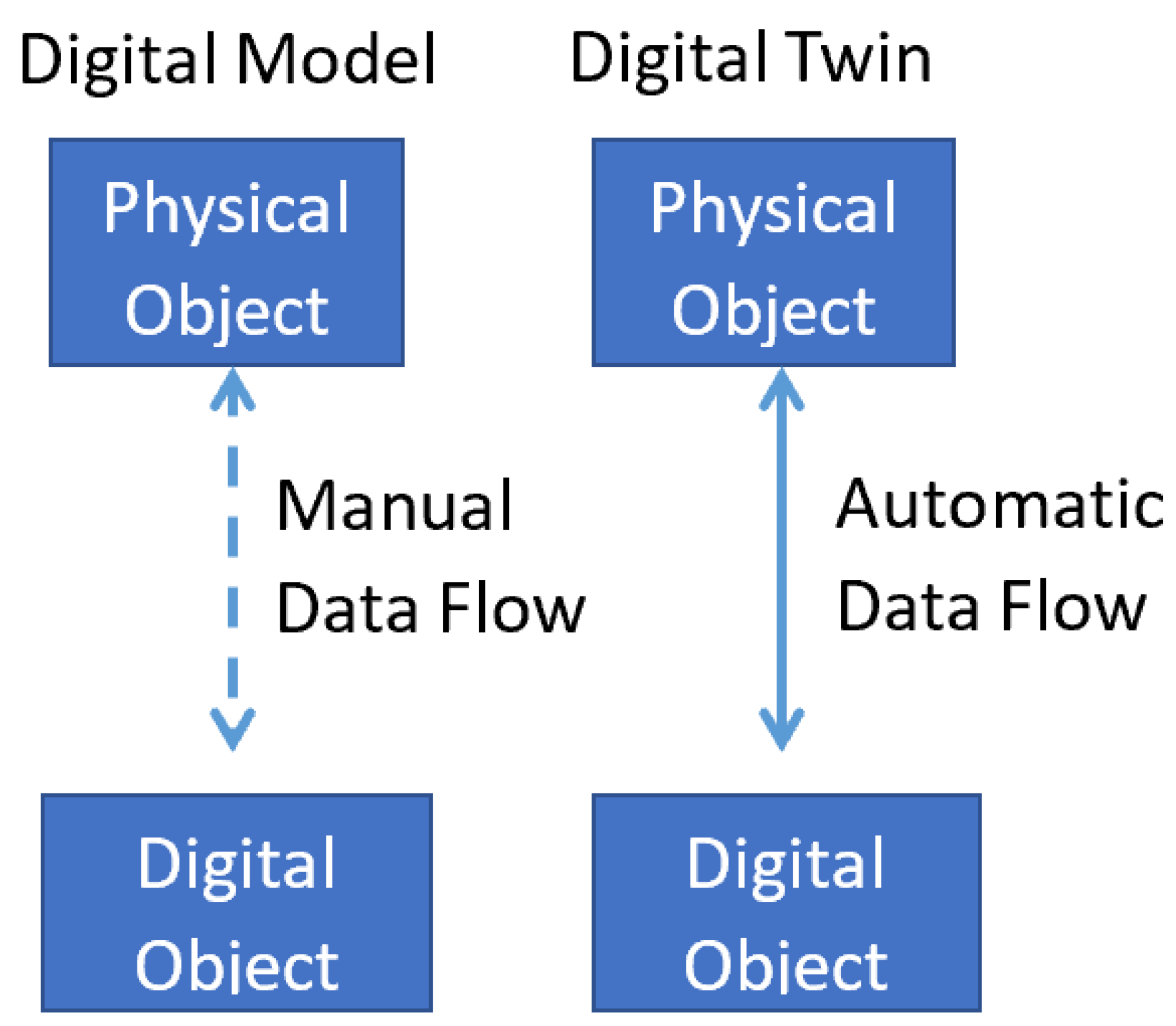
Recently, the interaction of a physical and digital machine, termed as digital twin (DT), with connectivity and data flow in both directions (as shown in Figure 1), is being actively pursued to increase the safety and reliability of aircraft and its systems through near-realistic predictive analysis [7]. It implies ensuring optimal fidelity level in order to attain an accurate assessment of system condition, as well as providing a viable prognosis as an integral part of the overall health management regime. This can be, however, further augmented with techniques such as those presented in this paper—the qualitative validation.
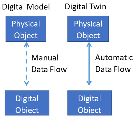
Figure 1.
The interaction between physical and digital objects depicting the difference between a “digital model” and “digital twin”.
The aforementioned approaches, aimed at optimizing the health management (including CBM) of electromechanical actuators and the aircraft electrical braking and anti-skid braking systems they serve, are limited to building models, factoring in different mechanical and electrical parameters, and then assessing their performance and reliability. On the one hand, the IVHM approach relies on the data acquired through multiple sensors and their analysis to maintain the integrity and ensure the availability of systems/sub-systems; digital models, on the other hand, provide efficient means of leveraging that data and constructing system performance and reliability profiles to help strategize associated maintenance activities. Our qualitative validation approach is a step further to augment and provide these approaches with more efficient and effective health management and condition-based maintenance regime for EMAs.
3. Development of the Electric Braking System (EBS) Model
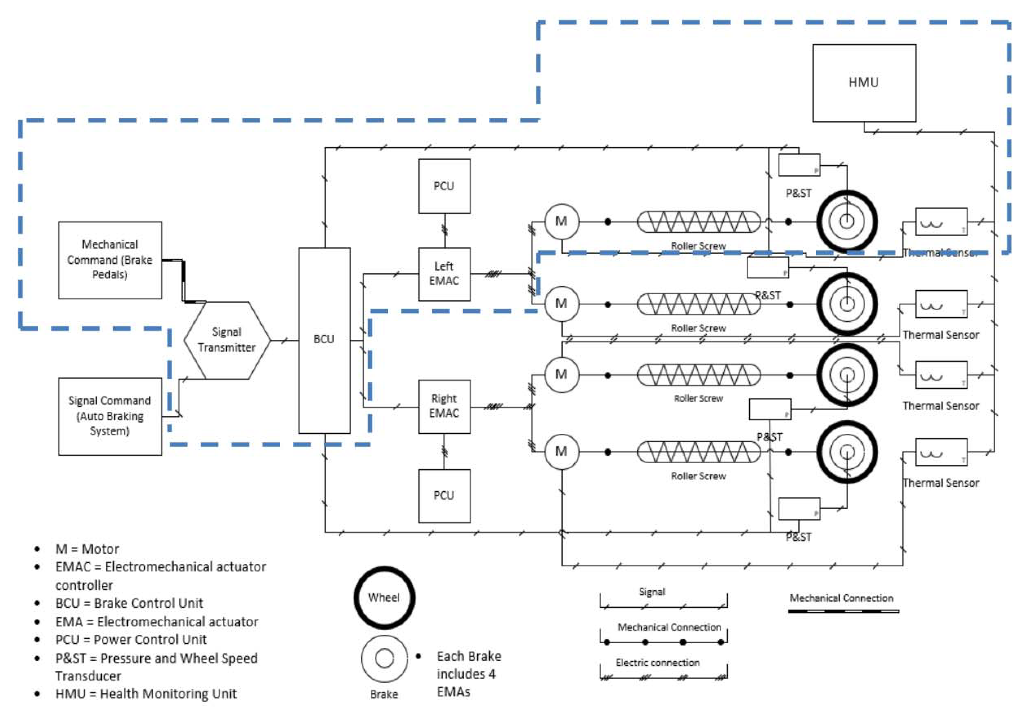
A simplistic architecture of an aircraft electric braking system (EBS) is shown in Figure 2. It consists of an electro-mechanical actuator (EMA), a braking control unit (BCU), EMA Controllers, sensors, and the wheels. The blue dotted lines signify a single EMA brake, whereas the single EMA connected to the brake acts as four actuators connected to the wheel for the simplification of simulation.
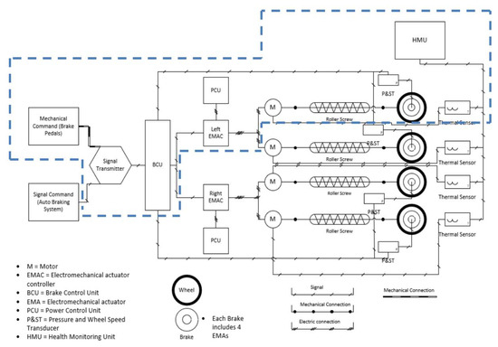
Figure 2.
The architecture of an aircraft electric braking system.
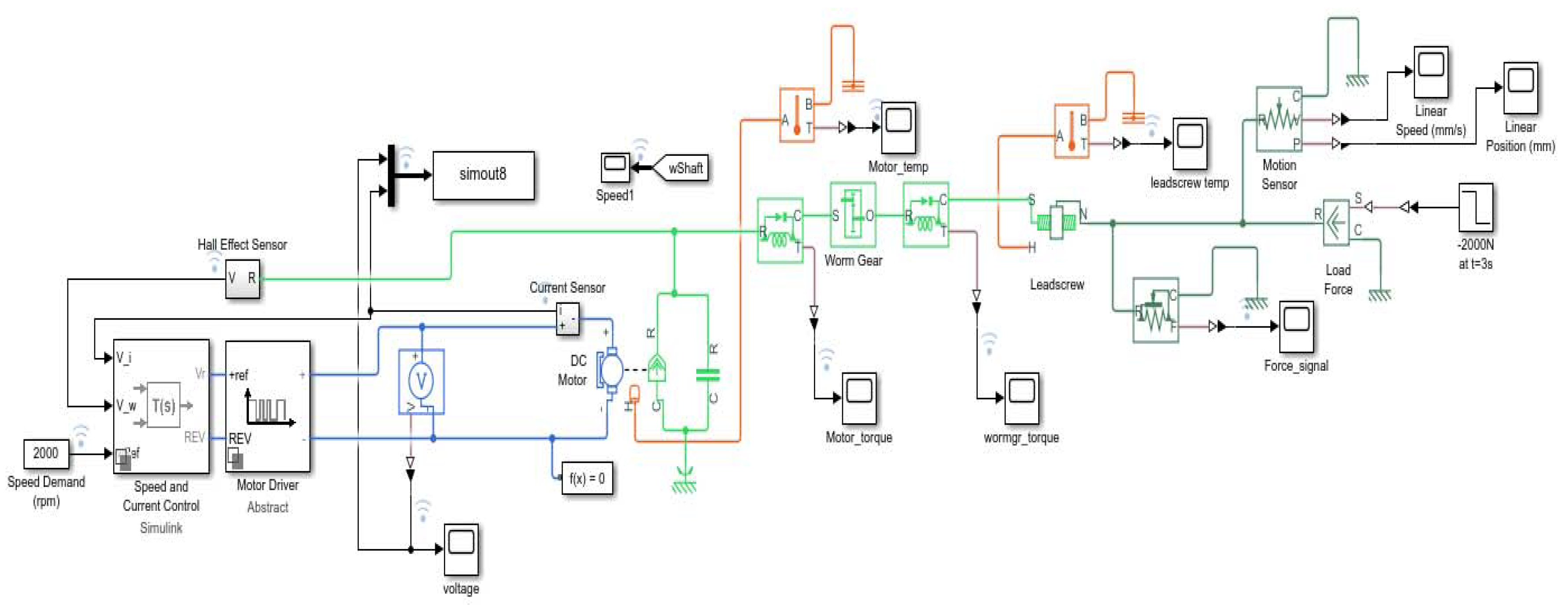
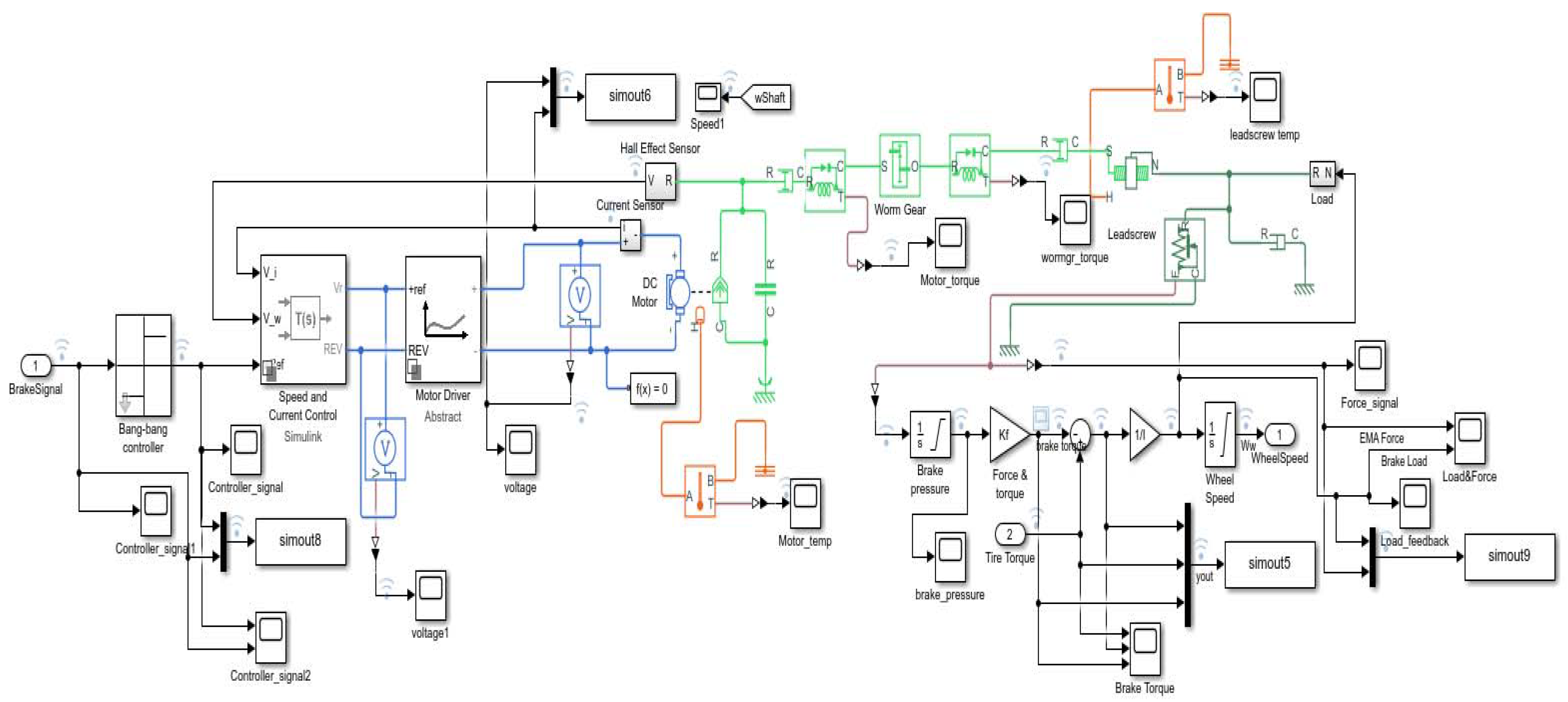
Based on this architecture (Figure 2), a highly representative digital model of electric braking system (EBS) including an anti-skid braking system (ABS) is developed in the MATLAB/Simulink environment using the Simscape library, as shown in Figure 3. The model is kept generic, meaning it does not mirror any specific aircraft braking system. It provides a scalable platform for fault modes integration, testing, and diagnosis. In order to have a suitable actuator for the simulation, a linear EMA with a worm gear and a leadscrew is used for the model.
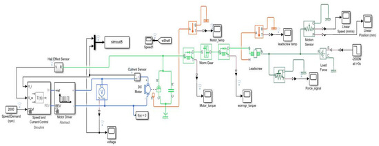
Figure 3.
The Simulink-based digital model of an electro-mechanical actuator (EMA).
3.1. Structure of the Linear EMA
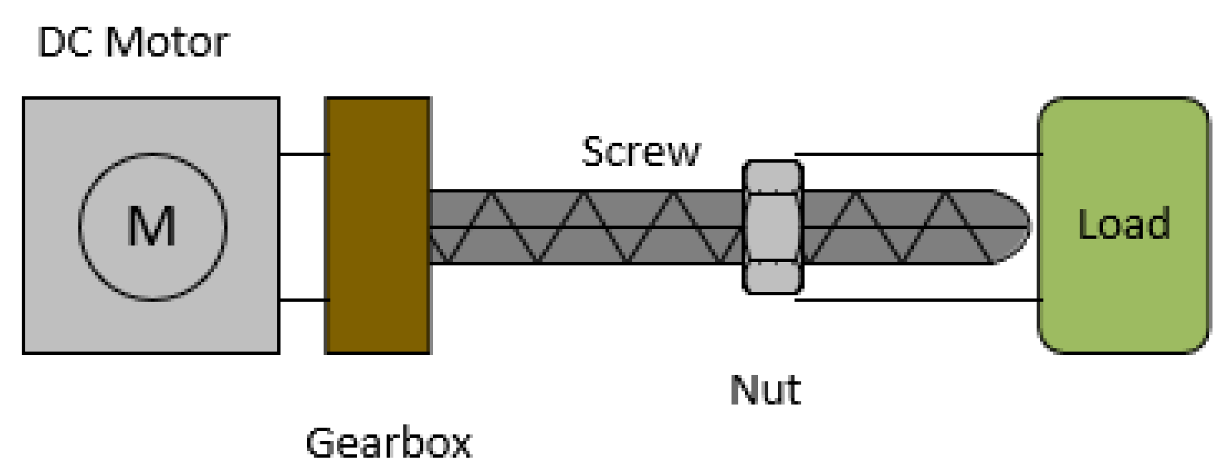
The component breakdown of the linear EMA is given in Figure 4. It is made up of the electric motor, a gearbox, leadscrew, nut, and an external load. The electric power provided by the energy source is converted into torque by the electric motor, which is then transformed into force and applied to the load.
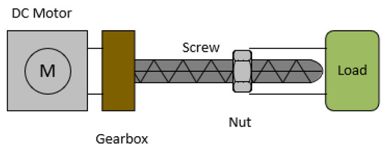
Figure 4.
The structural diagram of a linear electromechanical actuator.
As for the displacement of the system, the rotational motion from the electric motor is then converted into translational motion by the leadscrew, as required by the load. In order to define EMA optimally, the electrical and mechanical properties similar to existing EMA models are used to provide values for the system sizing and constraints.
3.2. The Electromechanical Actuator Model
Following the EMA definition, the basic components necessary to recreate the actuator are selected and integrated into the model, as shown in Figure 4. Firstly, an electric motor with a voltage source is used to power the system. Voltage, current, and temperature sensors are then inserted into the model to obtain useful data on the behaviour of the actuator.
As is evident from Figure 4, after the motor there is a worm gear (gear box), which enables the required increase in the torque provided primarily by the electric motor. Torque sensors before and after the worm gear are also included in order to verify the increment in the torque values as expected. The leadscrew is at the end of the system, providing the force output as required. A temperature sensor is also included to measure temperature variations under different operational conditions, which may impact the component performance. Finally, a step motor is included alongside an ideal force source to simulate as a load. A force sensor is placed in proximity to obtain essential data from the leadscrew.
It must be noted that the speed and current controller are placed as a first step whilst developing the model to condition the signal for the motor driver. The motor driver, coupled with a pulse-width modulation (PWM) voltage control and an H-bridge, is placed before the motor to provide suitable power to the motor. Frequency and voltage supplied by the motor driver to the electric motor provide normal operation. Once the EMA model is completed, the development and conditioning of the ABS system is undertaken, in order to integrate it into an EBS during further stages.
3.3. The Anti-Skid Braking System Model
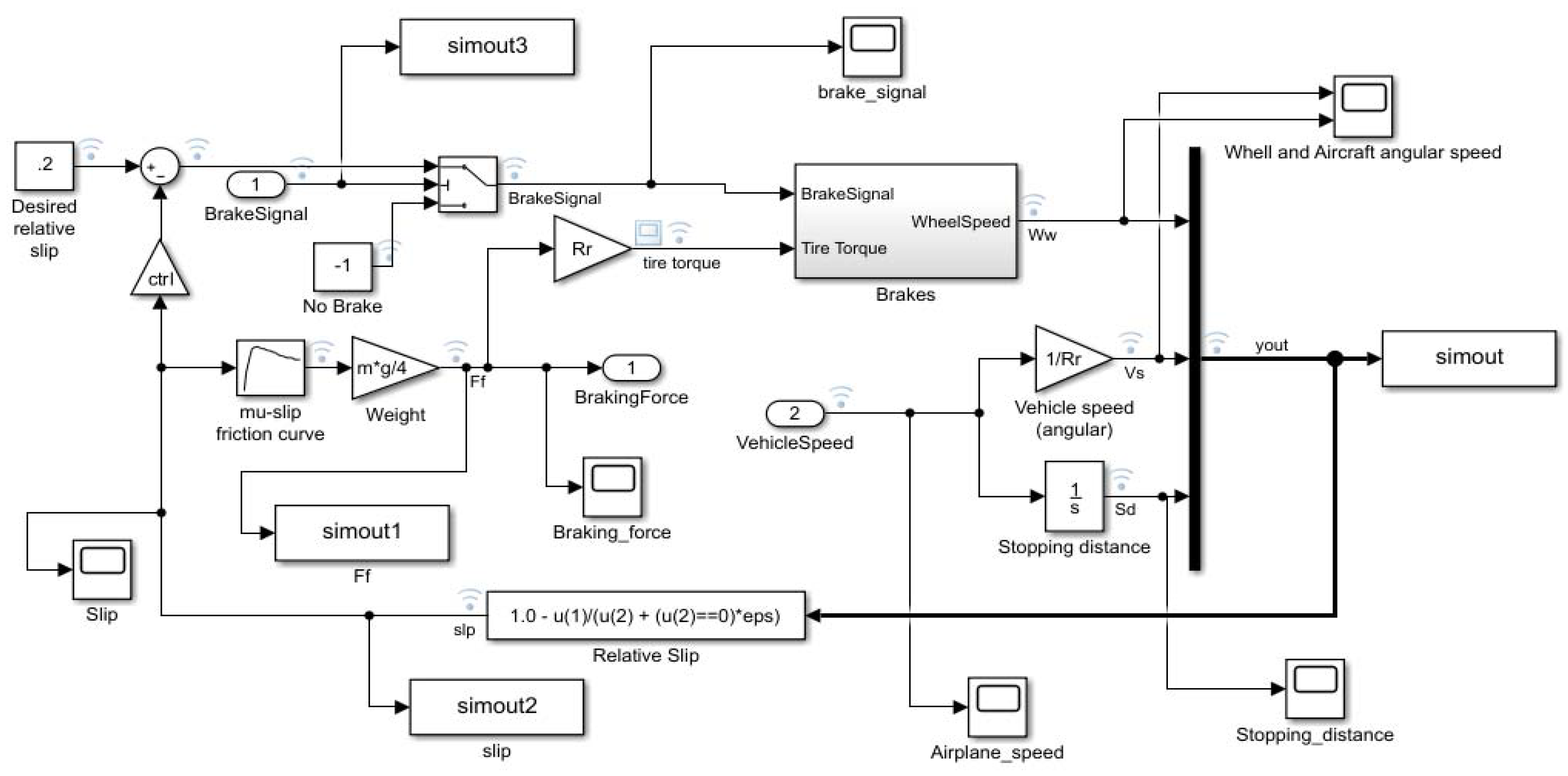
The ABS system is an important addition to the electric braking system by virtue of its capability to provide the required performance enhancement. It is worth mentioning that, as shown in the braking system architecture (Figure 2), the ABS system is part of the braking control unit (BCU). Figure 5 shows the ABS system used for the model simulation.
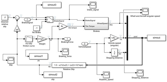
Figure 5.
The Simulink model of the anti-skid braking system.
To begin with, a normalized desired slip value of 0.2 is considered, in line with the preferred values, between 0.18 to 0.3, recommended in [12], for better system performance. The brake signal initiates the brake procedure after 1 s of the start of the simulation process. It is also considered prudent to implement a control gain to turn the ABS system on or off, as required by the simulation.
All the pertinent information (such as “vehicle weight” and “wheel radius”) about the aircraft is inserted into the ABS system. The tire torque value is obtained by the multiplication of those values, integrating the friction slip curve. The tire torque value is used during future stages of the simulation as it interacts with the EMA.
Different data can be collected at this stage of the model, such as the wheel and aircraft angular speed, stopping distance, airplane speed, braking force, and slip. As mentioned previously, the slip is an important value to monitor the performance of the brake.
3.4. Electric Braking System Integration
Once the EMA model is developed and functioning, it is integrated with the ABS system, thus representing a holistic electric braking system. The interaction between the ABS system and the EMA is shown in Figure 6. It is noted that Simulink common blocks and Simscape components are used and connected accordingly, considering different units and magnitudes provided by the model.
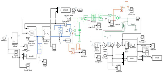
Figure 6.
The integrated model of electric braking system combining EMA and anti-skid braking system (ABS) models.
As can be observed in Figure 6, the ABS controller receives the braking signal and continues its conditioning before it is supplied to the EMA. The speed and current controller provide the voltage to the electric motor for generating PWM depending on the signal from the ABS controller. Torque is generated by the electric motor, increased by the gear box, and then converted into translational motion by the leadscrew.
The resultant force provided by the EMA is then properly conditioned by a force sensor and subsequently converted into torque by the Simulink blocks, to obtain the brake torque. The tire and brake torque are subtracted to obtain the resultant torque, which is then used as a load feedback to the actuator. The resultant torque is finally integrated to obtain the wheel speed, which is returned to the ABS system and used to control the wheel slip and the resultant tire torque.
Finally, simulation is iterated until the aircraft stops and provides a complete reading of the behaviour of the system, considering also no drag or other means of braking. As mentioned previously, different scenarios are modelled to obtain the system behaviour when certain fault modes are present using Simscape blocks and specific conditions.
4. Electric Braking System and Fault Modes Simulation
4.1. Braking System Simulation Parameters
Once the EMA has been integrated into an EBS, parameters are added to the model. Table 1 shows the EMA parameters used for the simulation. The required values were obtained from an existing actuator, that has been used as a baseline. Other parameters, such as motor armature inductance and motor rated speed were obtained from the base DC motor block parameter provided by MATLAB/Simulink.

Table 1.
The parameters of EMA used for simulation.
As for the physical blocks, damping, friction, and spring rate parameters were iterated until a suitable simulation was obtained. Controller values, such as gains and limits were modified accordingly to provide good actuator performance.
Following the EMA definition, aircraft and ABS parameters are given in order to provide a suitable scenario for the actuator. As no specific aircraft is being targeted, the values selected for the model assure that the simulation is produced accurately. Table 2 shows various aircraft and ABS parameters used.

Table 2.
Different aircraft and ABS parameters for simulation.
The EBS model in the simulation is used to represent a realistic approach of a brake using an EMA, without considering any other means for braking in an ideal scenario. Using Equation (1), the approximate stopping distance can be calculated as a function of the initial velocity and the ratio of friction force and vertical load (MU), assuming the values we defined previously [22].
where Mu is assumed as 1, E is the desired wheel slip 0.2 and g is the gravity constant 9.81 m/s2. The results show that the aircraft will take about 2 km to achieve full stop, so a similar distance should be expected from the ABS simulation to verify the proper integration of the model. In order to estimate the power required by the brakes to stop the vehicle, Equation (2) obtained from [21], derived from a free body diagram of an aircraft, can be used:
where is the velocity of the aircraft, starting from , and is the braking force required to stop the aircraft. Using an expected and estimated average braking force of 19 kN similar to the one used by [21], the peak braking power required to achieve full stop is found to be 1.67 MW, whilst the average power stands at 0.84 MW. As seen on the ABS system diagram (Figure 5), the wheel slip can be obtained by dividing the aircraft longitudinal speed by the wheel angular speed, as shown in Equation (3):
where is the wheel angular speed and is the aircraft longitudinal velocity. The wheel slip is 0 when both velocities are equal which means a non-braking condition exists. On the other hand, when the slip value is 1 due to the wheel being blocked, the angular speed drops to zero. Equation (4) represents the aircraft wheel speed as follows:
Dividing the aircraft linear speed by the wheel radius, the vehicle angular velocity is calculated. Stopping distance and the braking power are used in the following sections to compare the model results with the previous works and validate the different scenarios used on the simulations. Lastly, the simulation time is set for the duration of 60 s.
4.2. Fault Modes Simulation
In order to provide highly useful information to develop an efficient CBM, knowledge of different fault modes and their corresponding impact is essential. We considered three main fault modes including the open circuit (OC), intermittent open circuit (IOC) and jamming. These three fault modes have a medium level of appearance, but very high criticality related to the safety of the system.
The OC is simulated by adding an electric switch between the motor controller and the electric motor [23]. As the switch opens, the electric current stops flowing and the EMA freezes in the position the fault mode occurs. Presumably, this may result in the lack of angular displacement and velocity from the electric motor and complete electric current breakdown.
As with the common OC, the IOC is the cut on electric connection from the electric source to the motor, but in this case, with an intermittence. The switch opens and closes intermittently, powering and cutting power to the electric motor. This may result in fluctuation in electric power and increased motor temperature.
In addition to the above, the jamming effect was also simulated by increasing the Coulomb friction to 50 kN, as suggested by [24]. Some of the expected results from this scenario include the lack of angular displacement of the motor shaft, no angular velocity, increased temperature of the motor and increasing electric power [25,26].
5. Qualitative Validation—Results and Analysis
This section presents the results obtained from the simulation of the developed digital model of EMA (Figure 6) in conjunction with ABS and EBS. Primarily, comparison between different scenarios (mentioned in Section 4.1) and the corresponding impact of fault modes on the system performance is drawn. The ‘Normal Operation’ condition is used as the base scenario with the best overall performance.
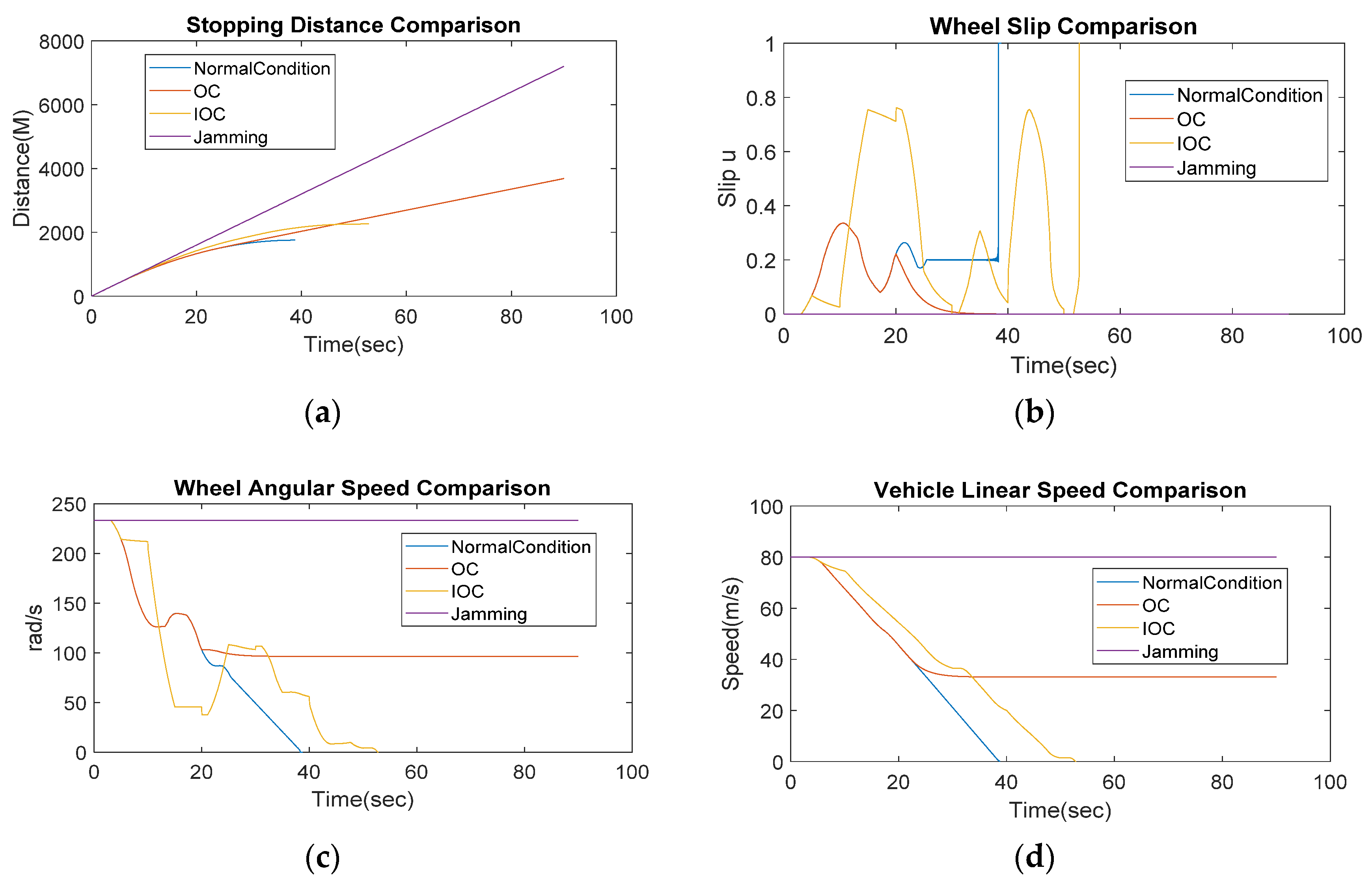
As can be seen in Figure 7, four key aircraft operation parameters, namely, Stopping Distance, Wheel Slip, Wheel Angular Speed, and the Vehicle Linear Speed are analysed against the EBS normal operation condition and the different fault modes. A significant impact is observable on all aircraft operation parameters with the introduction of faults, when compared with the ‘Normal Condition’ base scenario.
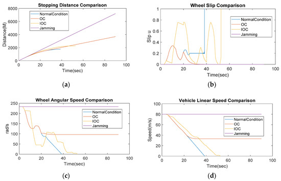
Figure 7.
A comparative impact analysis of different fault modes with the Normal Operation conditionof EMA (a) Stopping Distance comparison; (b) Wheel Slip comparison; (c) Wheel Angular Speed comparison; (d) Vehicle Linear Speed comparison.
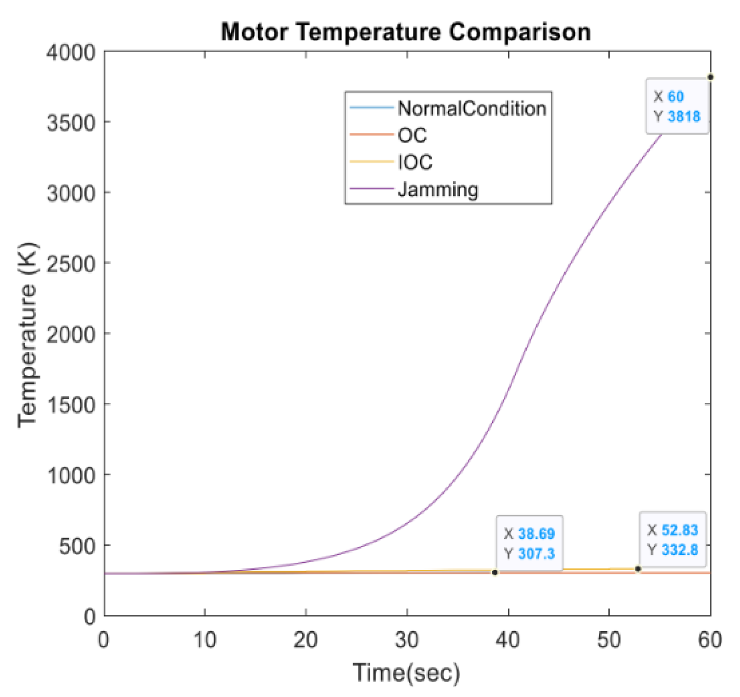
Most significant is the impact of “jamming,” as it halts the braking function of the aircraft altogether. The OC fault mode is similar to jamming in a way that as soon the signal brakes, it stops braking. The IOC also shows a reduction in performance when compared with the normal condition scenario. It is important to note that the jamming presents very hazardous environment, which may result in the damage to the actuator and other equipment near the actuator. The wheel and the brake itself can suffer notable issues with possible severe consequences for the aircraft. Figure 8 shows the change in the motor temperature. It can be seen that jamming causes maximum increase in temperature as compared with other fault scenarios, which could potentially lead to a hazardous situation compromising the integrity of the actuator and other peripheral systems. As for the OC and IOC, the increase in temperature seems much less dangerous; nevertheless, it indicates an ongoing fault in the system.
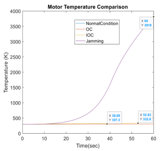
Figure 8.
The impact of fault modes on the temperature of the EMA.
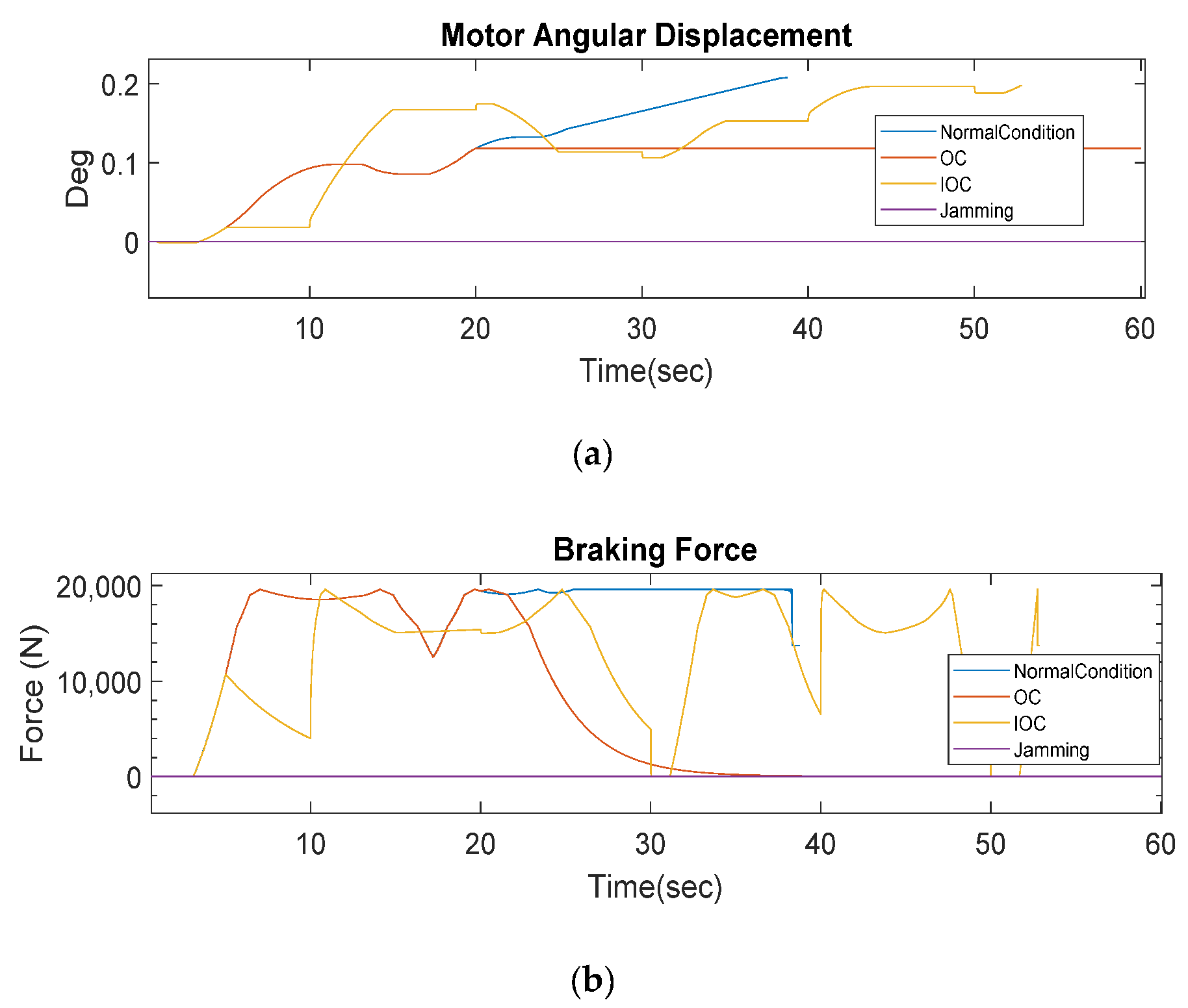
Similarly, the performance degradation trend is quite evident on the motor angular displacement and braking force, as shown in Figure 9. Again, jamming presents the maximum impact leaving the system with no force and angular displacement. OC stops abruptly as expected and IOC displays a considerable reduction in performance.
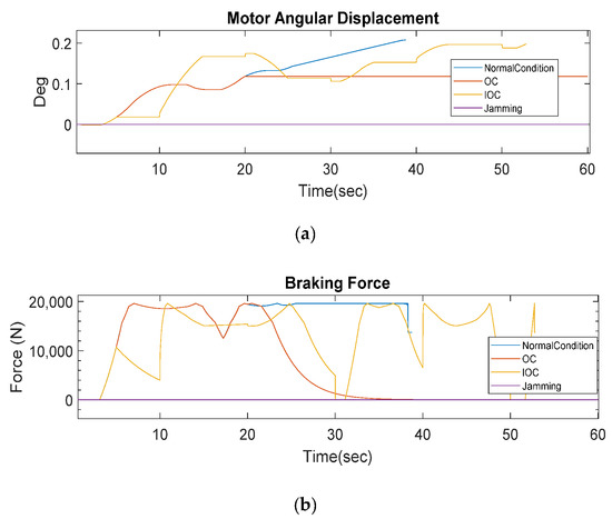
Figure 9.
The impact of fault modes on motor angular displacement and braking force; (a) motor angular displacement; (b) braking force.
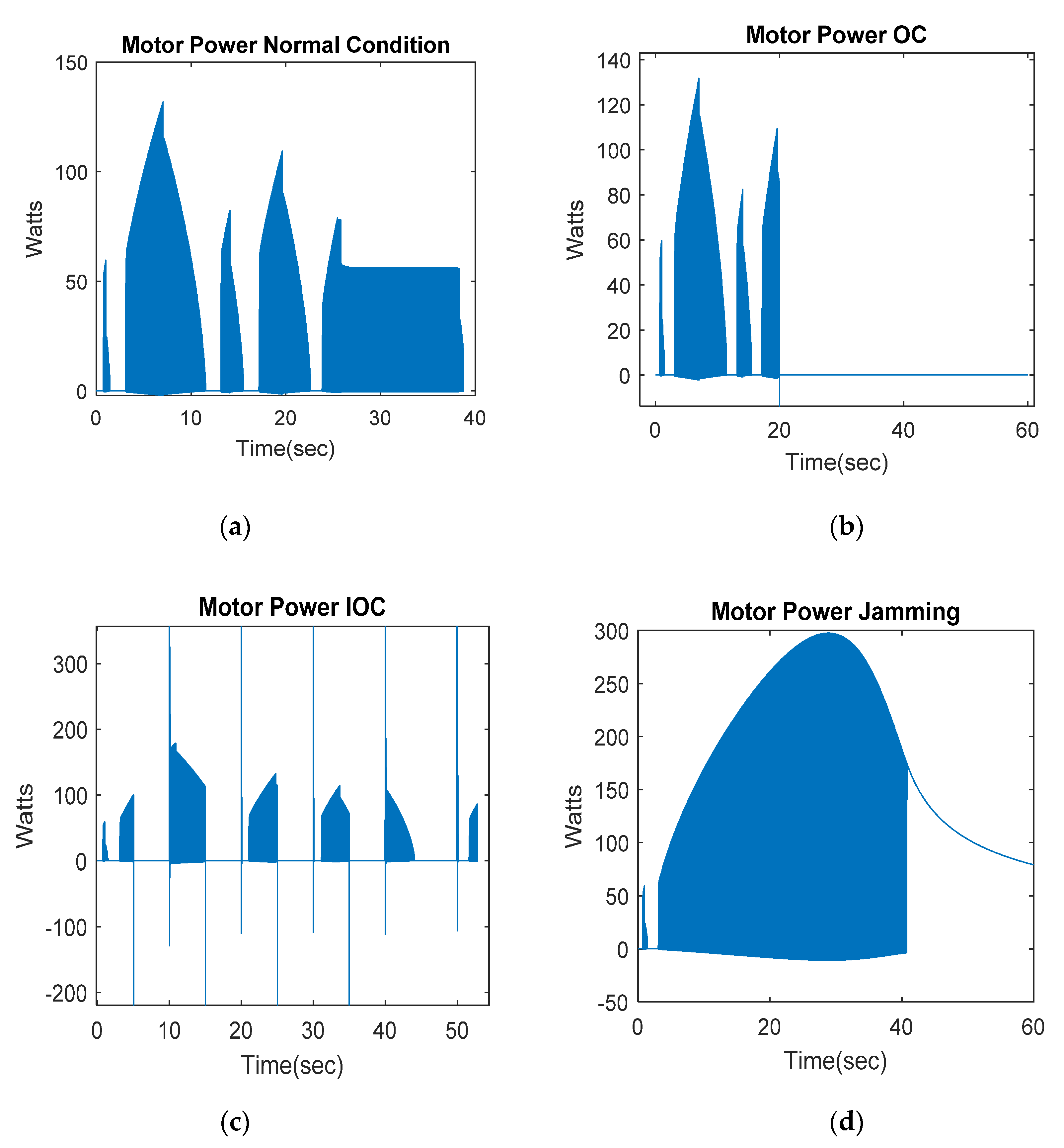
Lastly, the impact of the fault modes on the power of electric motor can be noted in Figure 10, where the normal condition (a) is compared with all the three scenarios. As is evident, there is a great variation in the electric power of the motor, which eventually impacts the overall performance of EMA. The scenario with the OC (b) shows the abrupt cut in power that affects the motor of the actuator, with a clear disruption in the system. In case of the scenario with IOC (c) displayed, the power cuts after every cycle and power spikes when the connection is closed, reducing the performance of the EBS. The fourth scenario (d) shows the electric power increasing with time as the actuator is subjected to the jamming condition, generating other disruptions, such as rapid temperature increase and no actuator displacement.
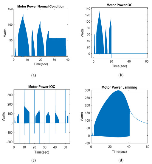
Figure 10.
The impact of fault modes of the electric power of the EMA electric motor (a) motor power in Normal Operation condition; (b) motor power in open circuit (OC); (c) motor power in intermittent open circuit (IOC); (d) motor power in jamming.
5.1. Qualitative Validation
It is important to assess and validate methods qualitatively so as to develop a better understanding of the issues presented by different operational fault scenarios [27]. This implies that the information can be gathered by differentiating the performance outcome of each scenario and accordingly setting up an expected baseline for more efficient system health evaluation.
Accordingly, a rubric scoring-based qualitative validation method is developed to evaluate the performance of the EBS under different scenarios with fault modes. An ascendant numerical qualification using numbers from 1 to 4 is given to describe the behaviour of the signal compared to the normal condition, with 4 representing the greatest change. The sum of the results obtained is compared to a range of values which define the fault mode. Table 3 describes the numerical assessment and the order used. Depending on the failure, a different combination in results can be expected and the failure identification process can be made. As seen in the previous section, the OC, IOC, and jamming have very different outcomes. Whilst the OC and IOC have electric power cut and no temperature change, with a jamming condition the same cannot be expected.

Table 3.
Qualitative validation method.
Table 4 shows the qualitative validation of the fault modes by comparing various related output signals. It is worth noting that each of them displays a specific value that can help identify the change each signal experiences. Comparing with the normal condition, the change in every signal is very noticeable, as all of them suffer from medium-to-great increase. The OC shows a complete lost signal as the electric connection of the actuator is disconnected.

Table 4.
Fault modes qualitative validation comparison.
5.2. Analysis
5.2.1. Normal Operation Condition
As a baseline, the normal operation scenario presents a smooth reduction on the aircraft speed achieved through proper control and modulation of the EMA by the actuator controller. The actuator provides enough force to the brake, which is capable of providing the required torque to stop the aircraft gradually. The wheel slip value is properly stabilized at 0.2 and provides a good difference in speed between the wheel and the aircraft.
With the actuator controller set at the specified parameters, the electric power is maintained at proper levels without having peak loads. The electric motor temperature increase is minimum, which suggests a good performance achieved by the controller. Moreover, the simulation shows the stopping distance of 2.1 km achieved under this scenario, which can be used to compare with the scenarios on which the aircraft actually achieves a full stop, such as the ABS OFF scenario, which stops after 2.6 km, showing a reduction in performance.
When comparing with the scenario in which the ABS system is OFF, the EBS fails to reduce the aircraft speed at the same pace as the wheel stops with the wheel slip at 1 and continues on that value until the end of the simulation. The force provided to the brake by the EMA is eventually reduced, which can be also seen on the braking torque, taking a longer time to stop the aircraft. The electric power from the actuator increases gradually to higher levels under the ABS ON scenario, which suggests a reduction in the performance of the system due to increase in the motor temperature.
5.2.2. Open Circuit
For this fault mode, the sudden cut of the electric power to the motor of the actuator presents an appreciable impact on the motor voltage, current, and controller signal which ultimately drop to zero as the switch transitions to “Open” state. This causes several other EMA data profiles to drop to zero as the actuator stops producing the braking force required for the aircraft to stop. The actuator staysor halts in the retracted position with no resultant braking torque.
It is also noteworthy that as the actuator shaft stops rotating with OC, the rise in motor temperature stalls and is maintained at the level it was at prior to the fault trigger. The qualitative validation of these data helps detect the occurrence of such a scenario, which indicates that the motor is not being powered electrically and it is not producing any torque, thereby rapidly providing an early stage diagnosis.
5.2.3. Intermittent Open Circuit
The IOC shows an abrupt power interruption with electric connection disrupting intermittently every 5 s. The data from the actuator controller show the fluctuating behaviour of the electric motor with intermittent power cuts and the subsequent power spikes occurring every time the connection switches between “Open” and “Closed” state. It helps understand the impact on the EMA and the controller as they experience functional challenges whilst aligning the braking procedure.
Under the IOC mode (contrary to OC), the aircraft manages to achieve a full stop but with a longer time (20% more) and distance (25% more) than it would under the normal operating conditions. The actuator becomes susceptible to damage or performance degradation with the increasing temperature values due to the power fluctuation and spikes and an improper modulation of the brake. As this information is validated qualitatively, an instant appreciation of the EMA and EBS health can be made and the maintenance regime can be adjusted accordingly.
5.2.4. Jamming
Under the jamming fault mode, as there is no movement from the EMA, there is no force applied and no ‘no-load’ feedback is available to the actuator. As a result, this prevents the controller from modulating effectively to achieve an unhindered braking procedure. The qualitative validation of jamming highlights the rapid increase in motor temperature due to higher current as a debilitating factor that may affect the reliability of EMA if it goes unnoticed and is not remedied promptly. In addition, considering the qualitative validation, the condition-based maintenance activities can be realigned to prevent the recurrence of jamming and help prolong the useful life of EMA and its associated equipment.
6. Conclusions
With the growing electrification requirements for more-electric aircraft (MEA), the enabling technology and systems must be on par with high reliability standards and maintained to the highest operational readiness levels. The existing health management regime that leverages several condition-based maintenance methods lacks the efficient and highly representative assessment techniques that could pinpoint the occurrence of faults in mission-critical systems and help realign the maintenance approach to foster system reliability. The qualitative validation approach presented in this paper plugs this gap and provides an efficient way of enhancing the existing CBM capabilities. Oriented towards electro-mechanical actuators (EMA) of an electric braking system (EBS), the newly developed qualitative validation is a rubric-scoring-based method that takes into consideration the sensor-based data on the change in behaviour of operational parameters under different aircraft operating conditions, differentiates, and classifies them according to the weighting score from 1 (min. change) to 4 (max. change). This helps with rapid identification of fault occurrence, building more robust remedial measures, and augmenting CBM capability for EMAs.
The whole qualitative validation scheme is built around a highly representative digital model of EMA integrated with an anti-skid braking system (ABS) model to provide a holistic EBS environment, more-realistic simulation with carefully selected three fault modes (open circuit (OC), intermittent open circuit (IOC), and jamming), and rigorous assessment of their impact on EMA performance and reliability.
As an early stage detection and analysis method, qualitative validation can be very useful to discard or include any relevant fault mode affecting the system. In addition, the developed qualitative validation method can be employed as an add-on to a digital twin (DT) environment for more rapid and realistic identification of faults in a given system. Furthering this research, we intend to expand the scope of fault modes (such as spalling, leadscrew structural problems, and other sensor issues) to build a large-scale EMA reliability database using qualitative validation for safe implementation in future more- and all-electric aircraft systems.
Author Contributions
Conceptualization, P.G., S.P. and A.W.; Investigation, P.G.; Methodology, P.G. and A.W.; Supervision, S.P., S.A. and A.W.; Writing—original draft, P.G.; Writing—review & editing, S.P. and S.A. All authors have read and agreed to the published version of the manuscript.
Funding
This research received no external funding.
Conflicts of Interest
The authors declare no conflict of interest.
References
- MOOG. Primary Flight Control Actuation System for 787. 2020. Available online: https://www.moog.com/products/actuation-systems/aircraft/primary-flight-control-actuation-system-for-787.html (accessed on 28 June 2020).
- SARAN. Boeing 787 Electric Brake: An Advanced Technology That Meets Airline Requirements. 2020. Available online: https://www.safran-landing-systems.com/media/boeing-787-electric-brake-advanced-technology-meets-airline-requirements-20170622 (accessed on 28 June 2020).
- Daggett, D.; Eelman, S.; Kristiansson, G. Fuel Cell APU. AIAA 2003, 1–9. [Google Scholar] [CrossRef]
- Gonzalez, C. Electromechanical Actuators. 2018. Available online: https://www.machinedesign.com/mechanical-motion-systems/article/21836654/engineering-refresher-the-basics-and-benefits-of-electromechanical-actuators (accessed on 23 June 2020).
- Gillespie, A. Condition Based Maintenance: Theory, Methodology & Application Amanda Gillespie Table of Contents. In Proceedings of the Reliability and Maintainability Symposium, Tarpon Springs, FL, USA, 26–29 January 2015. [Google Scholar]
- Fuller, A.; Member, S.; Fan, Z. Digital Twin: Enabling Technologies, Challenges and Open Research. IEEE Access 2020, 8, 108952–108971. [Google Scholar] [CrossRef]
- Jones, D.; Snider, C.; Nassehi, A.; Yon, J.; Hicks, B. Characterising the Digital Twin: A systematic literature review. CIRP J. Manuf. Sci. Technol. 2020, 29, 36–52. [Google Scholar] [CrossRef]
- Smith, M.J.; Byington, C.S.; Watson, M.J.; Bharadwaj, S.; Swerdon, G.; Goebel, K.; Balaban, E. Experimental and analytical development of health management for Electro-Mechanical Actuators. In Proceedings of the 2009 IEEE Aerospace Conference, Big Sky, MT, USA, 7–14 March 2009; pp. 1–14. [Google Scholar]
- Quattrocchi, G.; Berri, P.C.; Dalla Vedova, M.D.L.; Maggiore, P. Innovative Actuator Fault Identification Based on Back Electromotive Force Reconstruction. Actuators 2020, 9, 50. [Google Scholar] [CrossRef]
- Ezhilarasu, C.M.; Skaf, Z.; Jennions, I.K. The application of reasoning to aerospace Integrated Vehicle Health Management (IVHM): Challenges and opportunities. Prog. Aerosp. Sci. 2019, 105, 60–73. [Google Scholar] [CrossRef]
- Ming, Z.; Hong, N.; Xiao-hui, W.; Enzhi, Z. Research on modelling and simulation for aircraft anti-skid braking. In Proceedings of the 2008 2nd International Symposium on Systems and Control in Aerospace and Astronautics, Shenzhen, China, 10–12 December 2008; pp. 6–10. [Google Scholar] [CrossRef]
- Petersen, I.; Johansen, T.A.; Kalkkuhl, J.; Ludeman, J. Wheel slip control in abs brakes using gain scheduled constrained lqr. In Proceedings of the European Control Conference (ECC), Porto, Portugal, 4–7 September 2001; pp. 3–8. [Google Scholar]
- Guo, J.; Jian, X.; Lin, G. Performance Evaluation of an Anti-Lock Braking System for Electric Vehicles with a Fuzzy Sliding Mode Controller. Energies 2014, 7, 6459–6476. [Google Scholar] [CrossRef]
- Liu, J.; Yang, J.; Xiao, Y. Study on electric brake system of civil aircraft. In Proceedings of the IEEE International Conference on Aircraft Utility Systems (AUS), Beijing, China, 10–12 October 2016; pp. 917–922. [Google Scholar] [CrossRef]
- Morselli, R.; Zanasi, R. A self-tuning abs control for electromechanical braking systems. IFAC Proc. 2006, 39, 620–625. [Google Scholar] [CrossRef]
- National Instruments. What Is a Pulse Width Modulation (PWM) Signal and What Is It Used For? 2019. Available online: https://knowledge.ni.com/KnowledgeArticleDetails?id=kA00Z0000019OkFSAU&l=en-GB (accessed on 22 July 2020).
- UltraMotion. X1-High-Performance Linear Actuator from Ultra Motion. 2020. Available online: https://www.ultramotion.com/wp-content/uploads/2014/11/X1_datasheetnew-sitesmall.pdf (accessed on 22 July 2020).
- UltraMotion. ServoCylinder. 2020. Available online: https://www.ultramotion.com/linear-actuators/#specialty (accessed on 22 July 2020).
- Peng, L.; Zhi-gang, G.; Jun, Z.; Ni, R. Power Loss and Heat Dissipation Characteristics of High-Power Electromechanical Actuators. MATEC Web Conf. 2018, 153, 03003. [Google Scholar] [CrossRef][Green Version]
- UltraMotion. Aerospace Linear Actuators. 2020. Available online: https://www.ultramotion.com/industries/aerospace-linear-actuator/ (accessed on 22 July 2020).
- Dunster, M.R.; Stockman, G.S. Alternative Methods of Aircraft Braking; Digital Worcester Polytechnic Institute: Worcester, MA, USA, 2016. [Google Scholar]
- Office of Regulatory Analysis and Evaluation Plans and Policy. Tire Pressure Monitoring System. 2001. Available online: https://www.nhtsa.gov/sites/nhtsa.dot.gov/files/fmvss/tirepressure-fmvss-138.pdf (accessed on 22 July 2020).
- Tleis, N. Power Systems Modelling and Fault Analysis—Theory and Practice; Elsevier Ltd.: Oxford, UK, 2008; ISBN 978-0-7506-8074-5. [Google Scholar]
- Fu, J.; Mare, J.C.; Yu, L.; Fu, Y. Multi-level virtual prototyping of electromechanical actuation system for more electric aircraft. Chin. J. Aeronaut. 2018, 31, 892–913. [Google Scholar] [CrossRef]
- Balaban, E.; Field, M.; Aurora, E.; Cquisition, D.A.T.A.A.; Field, M.; Ntroduction, I. A Diagnostic Approach for Electro-Mechanical Actuators in Aerospace Systems. In Proceedings of the IEEE Aerospace Conference, Big Sky, MT, USA, 7–14 March 2009; pp. 1–13. [Google Scholar]
- Wander, J.; Romero, C.; Campillejo, Á.D.; Hidalgo, A.G. Simulation of electromechanical actuators with ballscrew and modelling of faults. In Proceedings of the Pegasus Student Conference, Madrid, Spain, 18–20 April 2018; pp. 1–9. [Google Scholar]
- University of Kansas. Qualitative Methods to Assess Community Issues. 2020. Available online: https://ctb.ku.edu/en/table-of-contents/assessment/assessing-community-needs-and-resources/qualitative-methods/main (accessed on 8 February 2020).
Publisher’s Note: MDPI stays neutral with regard to jurisdictional claims in published maps and institutional affiliations. |
© 2020 by the authors. Licensee MDPI, Basel, Switzerland. This article is an open access article distributed under the terms and conditions of the Creative Commons Attribution (CC BY) license (http://creativecommons.org/licenses/by/4.0/).

