Article

Crack Width and Propagation in Recycled Coarse Aggregate Concrete Beams Reinforced with Steel Fibres

by
Mansour Ghalehnovi
1,
Arash Karimipour
2,
Jorge de Brito
3,* and
Hamid Reza Chaboki
4
1
Department of Civil Engineering, Ferdowsi University of Mashhad, Mashhad 91779-48974, Iran
2
Department of Civil Engineering, Texas University at El Paso. Member of Center for Transportation Infrastructure Systems (CTIS), El Paso, TX 79968, USA
3
Department of Civil Engineering, Architecture and Georresources, Instituto Superior Técnico, Universidade de Lisboa, 1649-004 Lisbon, Portugal
4
Department of Civil Engineering, University of Birjand, Birjand 97174-34765, Iran
*
Author to whom correspondence should be addressed.
Appl. Sci. 2020, 10(21), 7587; https://doi.org/10.3390/app10217587
Submission received: 23 September 2020 / Revised: 10 October 2020 / Accepted: 20 October 2020 / Published: 28 October 2020
(This article belongs to the Special Issue Advances in High-Performance of Eco-Efficient Concrete)

Abstract

:
Reducing the crack width is a vital feature for protecting rebars from corrosion. In this investigation, the impact of steel fibres (SFs) on the cracking of recycled coarse aggregate reinforced concrete (RCARC) beams was investigated. Twenty-seven reinforced concrete (RC) experimental samples (150 mm × 200 mm × 1500 mm) were manufactured. Shear rebars were considered with different spacings. Specimens were tested under a four-point flexural setup. Recycled coarse aggregate (RCA) from a destroyed building was employed at 0%, 50% and 100% by weight. SFs were added at three contents (0%, 1% and 2%) in order to reduce the crack width. The mid-span load–displacement relationship and the crack propagation and width were measured during the tests. Therefore, this study intended to assess the impact of utilising RCA and natural coarse aggregate on cracks’ spacing and propagation in RC beams when SFs were employed. The obtained outcomes were compared with the requirements of CSA S474, NS 3473E, EC2-04, CEB-FIP and ACI 224R-01. It was found that enough shear rebars should be provided through the beams to control the crack width and propagation, but that SFs enhanced the bending performance of RCARC with no shear rebars.

1. Introduction

The corrosion of rebars accelerates when cracking occurs in reinforced concrete (RC) members. Cracking in RC is a phenomenon that cannot be avoided under tensile or flexural loading. Many types of research have been performed on the width of cracks in RC members [1,2,3,4,5,6,7,8,9]. Cracking occurs because of exceeding the concrete tension strain from the maximum tension capability. Therefore, rebars endure the tension force beyond what caused the cracks [10,11,12,13,14]. In many theories, slip is ignored at the first stage of cracking [11,12,13,14]. Therefore, the sections do not remain in place in the crack section.
Arora and Singh [15] studied the flexural performance of a concrete beam made with 100% recycled coarse aggregate (RCA) that was subjected to fatigue failure. The results were compared with those of natural coarse aggregate (NCA) concrete beams. They revealed that using 100% RCA in concrete in the place of NCA resulted in poor fatigue performance. Choi and Yun [16] studied the long-term deflection and flexural performance of reinforced concrete beams with RCA. The specimens were loaded for 360 days. Furthermore, the experiments were compared with ACI 318 analytical outcomes and a new model was proposed to calculate the long-term flexural deflections. Similar crack patterns were observed, regardless of the aggregate type, even though several cracks occurred in the beams made with recycled aggregate. Azad [17] studied the flexural behaviour of reinforced concrete beams made with recycled waste materials. In this study, polyethylene terephthalate (PET) wastes were used as a recycled material. The results indicated that PET waste could be used in concrete in proportions up to 15%. Gao and Zhang [18] investigated the flexural behaviour of steel fibres (SF) RCA concrete. The flexural strength, toughness and deflection dramatically improved by increasing the SF content. Based on previous studies, it is clear that adding SFs to RCA concrete beams is an effective method for improving their performance. Seara-Paz et al. [19] evaluated the influence of RCA on the flexural performance of reinforced concrete beams. The specimens were subjected to four-point loading after 28 days. The cracking behaviour showed differences between RCA and conventional concrete. Therefore, it is possible that using SFs could enhance the bending performance of RCA beams. Tošic et al. [20] compared the flexural performance of RCA-reinforced concrete with the Eurocode equations, based on 217 experimental specimens. They found that Eurocode 2 could anticipate the bending and shear resistance of RCA concrete beams without stirrups. Tarek et al. [21] used brick as the RCA to manufacture specimens. The results were compared with the proposed ACI 318-14 model to predict the flexural performance of the concrete beams. In comparison with virgin brick aggregate, the use of RCA did not reduce the cracking moment nor the maximum load-bearing capacity of the specimens. Zaetang et al. [22] used RCA at 0%, 20%, 40%, 60%, 80% and 100% by weight to produce concrete. Although the RCA beams were weaker than the NCA beams, improvements in the strength and abrasion resistance were obtained because of better bonding between the RCA and the cement paste due to the increased surface porosity and roughness of RCA.
Conversely, SFs offer a solution for reducing crack propagation. In some studies, the shear cracking in RC beams was investigated by using SFs only, a shear rebars ratio and the combination of stirrups and SFs [23,24,25,26]. Furthermore, the post-cracking stress transferability in concrete increases by increasing the SF content [27,28,29,30,31,32]. To evaluate the correct potential of the fibres, the transferred post-cracking stress through cracks must be considered by including an additional contributing term [33]. The slip occurred in tension rebars. Therefore, the load–displacement relationship can be measured as a criterion to study cracking [34,35,36,37,38,39,40]. Additionally, high SF contents improve the tensile strength of concrete members by improving the bond resistance between the concrete and rebars [41]. Conversely, if an insufficient SF content is used, the tensile strength is not considerably enhanced [42]. In 2008, Kim et al. [43] investigated the performance of FRC beams with four kinds of fibres and two SF contents (0.4 and 1.2%). According to the results, high strength steel twisted fibres perform significantly better than other SF in a higher strength matrix. Altun and Aktas [44] evaluated the influence of SF on the bending behaviour of lightweight concrete beams. Therefore, cracks propagate faster in RC members manufactured using lightweight concrete than in normal and high-strength concrete. It was shown that SFs increase the toughness capacity of prismatic concrete beams and their ductility. Yoo et al. [45] studied the post-cracking performance of normal and high-strength SF-reinforced concrete beams. The flexural strength, post-peak ductility and deflection capacity significantly increased by using a 1% SF content.
Mertol et al. [46] evaluated the effect of SF contents on the flexural behaviour of RC beams. For over-reinforced specimens, the post-peak stiffness of the beams was significantly lower than that of normal-weight concrete specimens. Patil and Single [47] tested SF reinforced concrete beams under predominant torsion and bending. They showed an improvement in the torsional strength, combined torsional–shear–bending strength and crack strength of the concrete when SFs were used. Luccioni et al. [48] investigated the static and dynamic behaviour of SF RC beams. Improvements were found in the static bending response with different fibre contents compared to those conducted under dynamic loading. Lee et al. [49] determined the structural response of SF RC beams under different loading values. The results indicated that the use of SFs improved the ductility of the beams regardless of the strain rate. Furthermore, the shear strength of the SF-reinforced beams substantially improved. RCA generally represents a way to change a waste creation into a reserve. Consequently, utilising demolished supplies as an alternative to natural ones could be a beneficial technique to keep the environment safe. RCA has widely been utilised in non-structural concrete elements and lower feature uses, such as back-fills and lower layers of roads, and natural aggregates have been used in a wide range of structures [50]. Alternatively, SFs not only delay the creation of cracks but also control their growth, and when combined with the post-crack bridging capability of fibres, SFs diminish the width of cracks when concrete is restrained [51]. In the hardened state, the interaction between SFs and mortar plays a bridging role in order to delay the widening of cracks. Therefore, if sufficiently high contents of SFs are provided in the specimens, the tension resistance of the concrete matrix will substantially increase. Furthermore, the bridging role of SFs in the mortar resulted in obtaining the composite performance of concrete that causes a transition from micro-cracks to macro-cracks and prevents increasing the cracks’ width. In concrete with a low fibre content, the fibres do not meaningfully enhance the tension and bending resistance of the concrete. Alternatively, in concrete containing a high SF content, the benefits of fibre reinforcement include raising the tension resistance, the strain-hardening response before cracking and a boosted stiffness beyond crack instalment [51]. When the member with fibres undergoes bending, their presence leads to enhancing the shear behaviour of the RC member. Furthermore, using fibres at the cracks’ location causes a postponement of the crack extension [52].
Different standards suggest different equations to predict the crack spacing and width in RC beams. According to CSA S474 [53], the average crack distance ( S m ) is calculated as follows:
S m ، C S A = 2 ( c + 0.1 s ) + k 1 k 2 d b h e f f b A s t ,
where c, s, b, d b and A s t are the reinforcement cover (mm), outer rebar’s layer distance (mm), cross-section width (mm), rebar diameter (mm) and outer area of the tension rebar’s layer (mm2), respectively. Furthermore, k 1 refers to the participation rate and boundary condition coefficients for rebars, which are considered equal to 0.4 and 0.8 for smooth and conventional rebars, respectively; k 2 is the strain coefficient, which is equal to 0.25 ( ε 1 + ε 2 ) / 2 ε 1 , where ε 1 and ε 2 
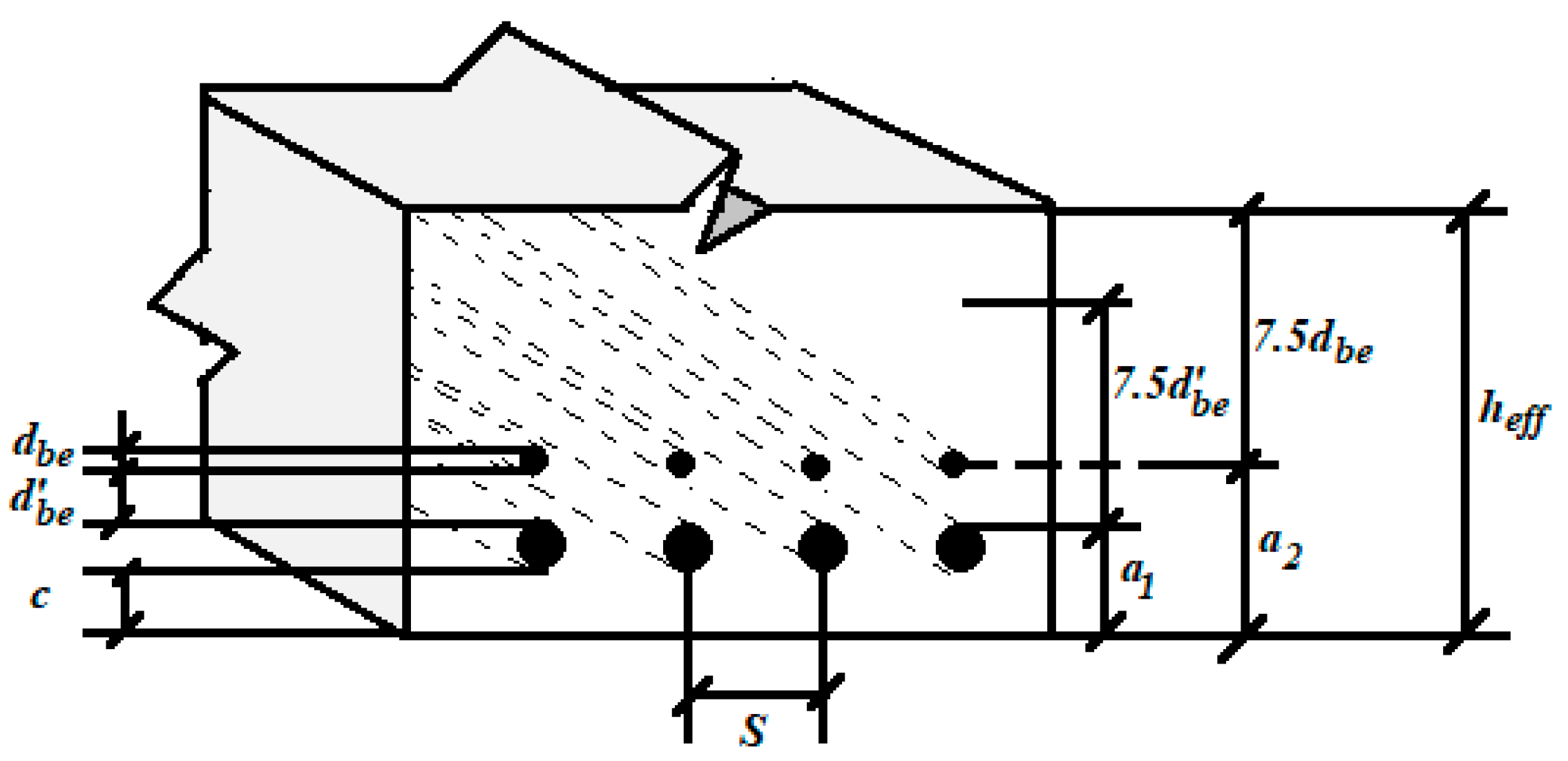
are the highest and lowest effective strains in the tensioned area, respectively. Moreover, h e f f is the effective tensioned depth (mm) and is considered equal to the largest amount of either a 1 + 7.5 d b or a 2 + 7.5 d b . Furthermore, it should not be much larger than the tensioned area or half the height of the section, according to CSA S474 [53]. Furthermore, it should not be much larger than the area of the tension or half the thickness as shown in Figure 1.
NS 3473E [54] presents a similar equation for calculating the average crack distance, as follows:
S m ، N S = 2 ( c + 0.1 s ) + k 1 k 2 d b ρ t N S ,
where c and s are the concrete cover’s and the outer rebar layer’s distance (mm), respectively. k 1 is an environmental factor that is based on the rebar’s corrosion, which is equal to 0.4 for ribbed rebars; k 2 is a strain factor equal to 0.25 ( ε 1 + ε 2 ) / 2 ε 1 , where ε 1 and ε 2 are the highest and the lowest effective strains in the tensioned area, respectively. ρ t N S 
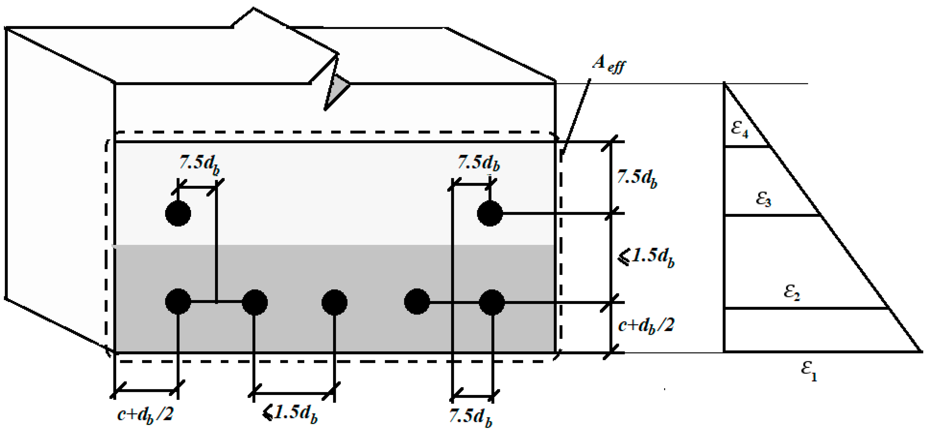
is the effective rebar’s ratio, equal to A s t / A c t , where A c t is the effective cross-section area of concrete and A s t is the area of the tensile rebars (Figure 2).
CSA S474 [53] and NS 3473E [54] propose a similar formula to anticipate the crack spacing, with little variance in the slope of strain, which calculates the effective rebar’s section. According to NS 3473E [54], the crack spacing is determined using the following relationship.
W k ، N S = 1.7 W m ، N S ; W m ، N S = r w ε 1 S m ، n s ,
r = 1 β 2.5 k 1 ( σ s r σ s ) 2 0.4 ,
where the correction coefficient r represents the plasticisers’ impact on the hardened concrete’s strain. ε 1 is the tensile strain in the outer tensile rebar’s layer, according to a non-axial stress distribution, with the main stress direction parallel to the longitudinal reinforcement, ε 1 = ε S = σ S / E S . σ S , E S and S m are the steel rebar’s stress, the steel rebar’s modulus of elasticity and the average distance between cracks, according to Equation (2), respectively. Furthermore, β is the conditional factor, which is defined according to the environment condition (in a natural condition with no humidity, it is considered equal to 1), and k 1 is equal to 0.4 for ribbed rebars. CSA-S474-04 [53] recommends calculating the average crack spacing according to average crack spacing as in Equation (1). According to EC2 [
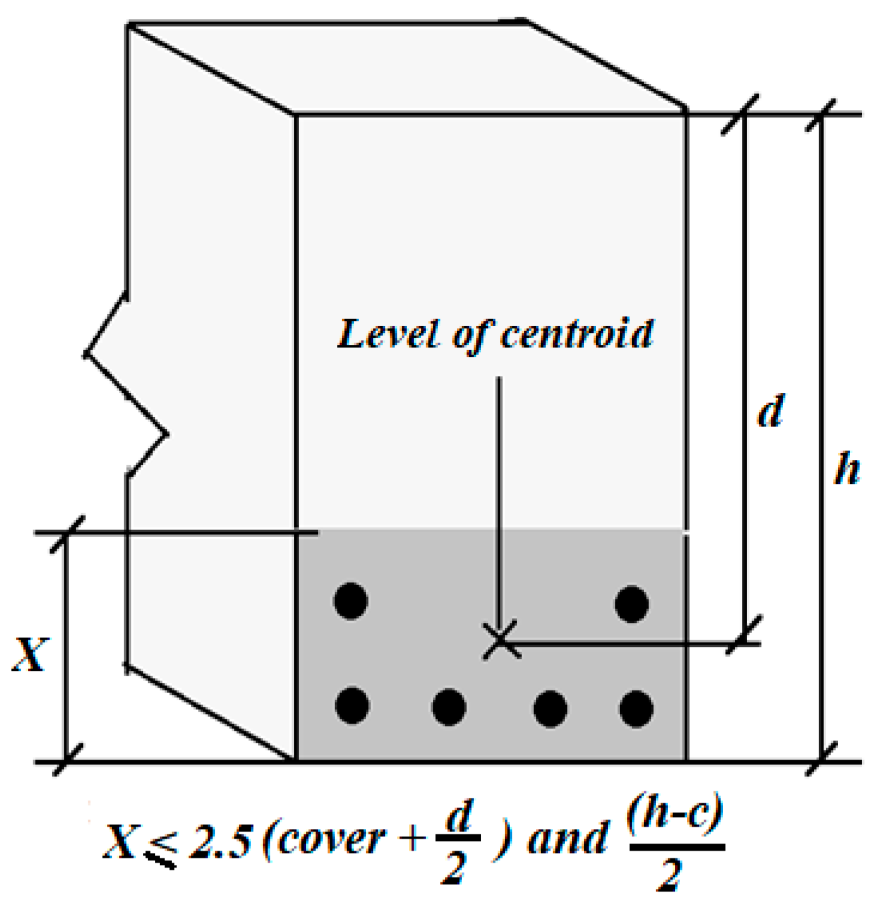
55], the concrete cover is the first parameter that affects the flexural crack’s spacing. According to this standard, the average flexural crack’s spacing can be obtained using the following formula:
S m ، E C 2 = 2 C + k 1 k 2 d b A c t 4 A s t ,
where C and d b are the reinforcement cover and diameter (mm), respectively. A s t / A c t is the effective cross-section rebar’s ratio.   k 1 is equal to 0.8 and 1.6 for ribbed and smooth rebars, respectively. k 2 is equal to 0.5 for members under bending and 1.0 for those under pure torsion (Figure 3).
The crack spacing ( W k ) is calculated as follows:
W k ، E C 2 = β E C 2 ; W m ، E C 2 = S m ، E C 2 ξ ε s 2 ,
where W k ، E C 2 is the design crack spacing, S m ، E C 2 the crack spacing according to Equation (3) and ξ is a dimensionless coefficient between 0 and 1. ε s 2 is the average strain under external load combinations. β E C 2 is the average cracking ratio for design purposes
CEB-FIP [56] suggests a different formula for predicting the crack spacing. According to this standard, the crack spacing can be obtained utilising the formula below:
S m ، C E B = 2 3 l s ، m a x ,
where l s ، m a x is the length of tension rebar’s slip, which can be calculated using Equations (8) and (9) for the complete cracking and first crack, respectively:
l s ، m a x = d b 3.6 ρ t C E B ,
l s ، m a x = σ s 2 2 τ b d b 1 ( 1 + α ) ρ t C E B ,
where σ s 2 is the rebars’ tension stress at cracking (MPa); d b is the rebar’s diameter (mm); τ b is the mean value of the boundary stress (MPa), which is equal to 1.8 f c t m ( t ) , where f c t m ( t ) is the average value of concrete’s tensile strength at cracking (MPa). ρ t C E B is the effective rebar’s area, equal to A s t / A c t , where A s t and A c t are the longitudinal rebar’s area and the concrete’s effective cross-sectional area, respectively. Furthermore, to simplify Equation (9), the value of (1 + α )can be considered equal to 1.0, where α is the ratio between the moduli of the elasticity of steel and concrete ( E s E c ) . CEB-FIP [56] offers the following equation to determine the flexural crack spacing:
w k ، C E B = l s ، m a x ( ε s 2 β C E B ε s r 2 ε c s ) ,
where ε c s is the free concrete shrinkage strain, ε s r 2 is the rebar’s stress due to the cracks under an equivalent load f c t m , which can be calculated as A c e f ε s r 2 = f c t m / A c e f ( 1 + α ρ t C E B ) . Furthermore, β C E B is a dimensionless constant and ε s 2 is the steel’s strain, which can be ignored in the transition section. Using ACI 224R-14 [
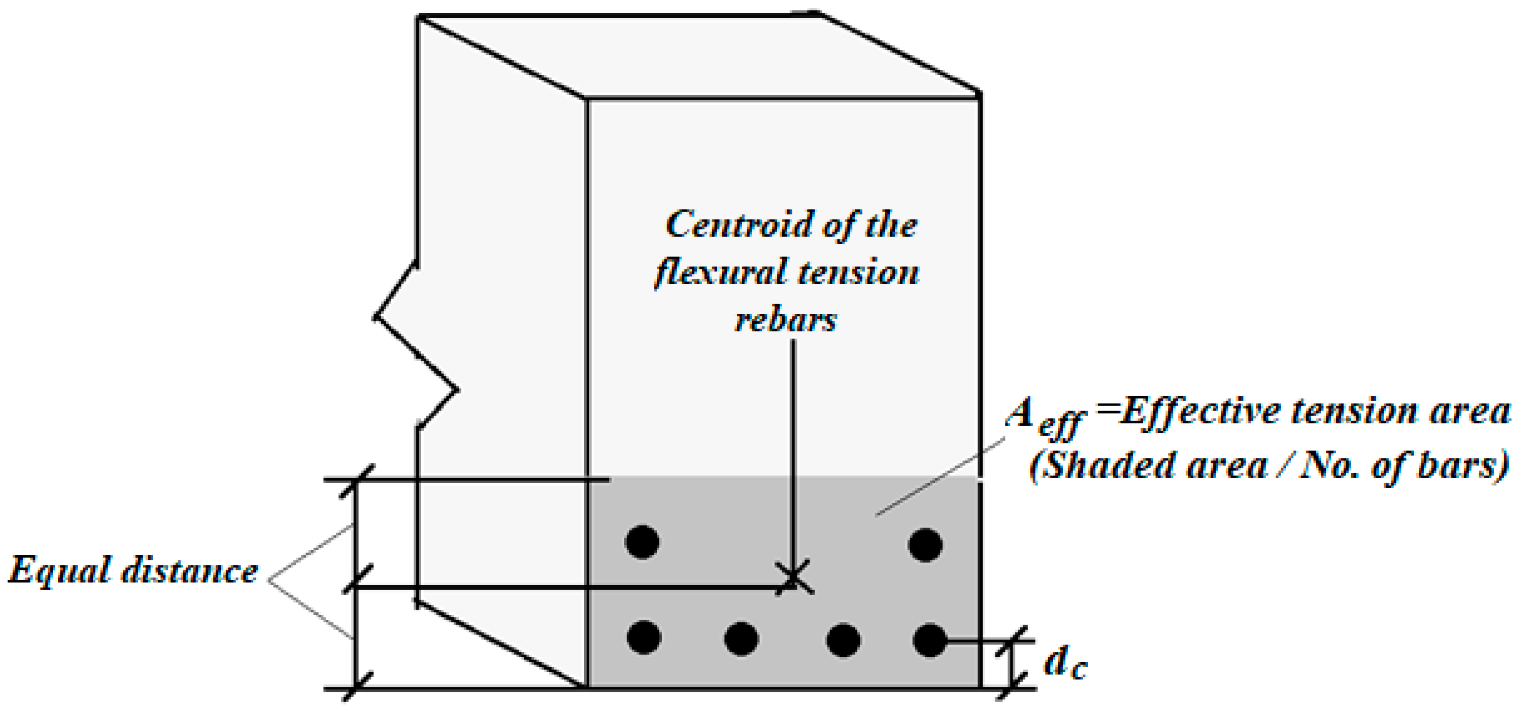
57], the maximum crack spacing in the beams and slabs is calculated based on static analysis. Thus, the maximum bending crack spacing can be calculated using the following formula:
W k ، A C I = 0.076 β A C I f s d c A 3 × 10 3 ,
where W k ، A C I is the maximum crack spacing (mm), f s is the steel rebar’s stress (MPa), d c is the cover of the outer tensile rebar’s layer (mm) and A the symmetrical concrete’s cross-sectional area (mm2). β A C I is a ratio equal to 1.2 times the space between the horizontal axis and the concrete’s outer tensile layer divided by the distance between the horizontal axis and the longitudinal rebars in the RC beam, as shown in Figure 4.
According to ACI 224R-14 [57], the moment crack spacing restricts the rebars stress f s at the cracked section under a load of 2/3 f y . Furthermore, the distance between the tensile rebar’s and concrete’s outer tensile layer (S) should not exceed the following value:
S ( m m ) = 15 ( 95000 540 f s ) 2.5 C c ,
where C c is the minimum distance between the surface tensile rebar’s or prestressed rebar’s and the concrete’s outer tension layer.

2. Research Significance

A short-term literature review indicated that many types of studies have been done to evaluate the crack spacing and width in RC beams. According to previous studies, crack spacing is slightly reduced by increasing the SF content. Alternatively, SFs can enhance the bending and shear behaviour of concrete beams [58,59,60] but the impact of RCA on the flexural and shear crack width and propagation has not been studied. Therefore, in this study, the influence of RCA and SF on the compressive and tensile strength of concrete was evaluated because the compressive and tensile strengths of concrete influence the flexural and shear strength of RC beams. This issue could also be observed in models proposed by several standards. Then, the influence of SFs on the crack spacing of RC beams manufactured using different values of RCA and NCA, as well as of the shear rebar’s spacing, was analysed. The main objective was to control the cracking and their propagation in RC beams when RCA was used, which is an important factor in the failure mode of RC beams and the corrosion potential of rebars. After the evaluation of cracking and their width in experimental specimens, the results were compared with those from numerical models proposed by several standards to show the ability of codes to predict crack widths when RCA and SFs are used.

3. Materials and Methods

3.1. Specimens’ Specifications

As discussed above, the crack spacing and propagation in SF RCARC beams was investigated. In this section, the properties of materials’ and specimens’ characteristics are described briefly.
The NCA was characterised according to the Chaboki et al. investigation [58]. In this research, RCA and NCA were used in specimens. The RCA came from demolished buildings and RCA was incorporated at 0%, 50% and 100% by weight. The used NCA and RCA are demonstrated in Figure 5 and Figure 6, correspondingly. Additionally, the grading graph of the aggregates is demonstrated in Figure 7. The characteristics of the aggregates were determined and are shown in Table 1.
Cement was mixed with the RCA, NCA and SFs, and then a solution of water and high-performance super-plasticiser was added to the mix until the SFs were uniformly distributed in the concrete mixture. The SFs were used at 0%, 1% and 2% (by volume). In addition, the NCA was substituted by RCA at 0%, 50% and 100% by mass. The concrete mix design properties and the compression and tension strengths for the various concrete mixes are specified in Table 2.
In Table 2, SF and RCA in the denomination of the mixes indicate the SF and RCA contents, e.g. 1SF-50RCA means 1% SFs by volume and 50% RCA by mass. Rebars with diameters of 20 mm, 10 mm and 8 mm were employed as tensile, compressive and shear rebars, correspondingly. The rebars were investigated in the direct tension setup and their specifications are shown in Table 3. To make the mixes, SFs with two bent ends were used. The tensile strength, modulus of elasticity and failure strain of the SFs were 200 GPa, 2 GPa and 3%, correspondingly. It should be stated that the length and equivalent diameter of the SFs were respectively 60 mm and 0.9 ± 0.03 mm, as shown in Figure 8.
In this study, a total of 27 RC beams with a 200 mm height, 150 mm width and 1500 mm span were produced using diverse SF and RCA contents. Shear rebars were spaced at 100 mm and 200 mm and without rebars. Three of these laboratory samples were selected as the control samples with no SFs or RCA. The geometrical characteristics and arrangements of the rebars are shown in Figure 9.

3.2. Test Setup and Loading Condition

After 28 days, the specimens were tested using a four-point bending setup. The beams were supported by round bars and two concentrated line loads, as shown in Figure 10a.
The test was carried out under displacement control circumstances and the stopping condition was set to be the failure of the specimens. The deflection of the beam was documented at each load step using Linear variable differential transformers (LVDTs). Furthermore, to measure the strain–stress performance of the cylindrical specimens, a laser strain gauge device was used, as shown in Figure 10b. It should be stated that the friction in this setup was automatically neglected by using the laser strain gauge. Conversely, to measure the crack widths in the beams, a mechanical calliper with an accuracy of 0.01 mm was used and the crack widths were recorded at each loading step. In addition, to measure the crack widths, a crack camera was used.

4. Results and Discussion

Since the compression and tension strengths of concrete determine the bending performance of concrete beams and their cracking, the impact of the SF and RCA contents on the concrete compression capability was studied. The results are represented in Figure 11. According to this figure, the cracking occurred only in the concrete surface when SFs were added and the specimen did not collapse, which became more perceptible when 2% SFs were added. The lack of concrete tensile strength led to collapsing of the specimen and the cores of the specimens were broken. Hence, by adding SFs, a resistant core of concrete specimens prevented it from collapse, and only the specimens’ surface was cracked and detached. This issue resulted from the bridging role of SFs that kept the particles close together and increased the tensile strength of the concrete. Alternatively, due to RCA’s higher and more angled specific surface compared to NCA, they were better impregnated with cement paste, which prevented the complete disintegration of the sample. Hence, the incorporation both SFs and RCA increased the adhesion between the cement paste and the aggregates and fibres. Therefore, more force was needed to separate the particles from each other and break than the unreinforced concrete, which improved the behaviour of the concrete.
The tensile behaviour of the concrete specimens with RCA and SFs was also studied. In order to investigate the failure of specimens under the Brazilian test (splitting tensile strength), the results are presented in Figure 12. According to this figure, a specimen with no SFs was divided into two parts. However, the addition of SFs prevented the two parts from separating when it failed due to the bridging role of the fibres in the concrete paste. Furthermore, using RCA weakened the tensile strength of the specimen, which could be compensated for by adding SFs. Hence, RCA could be used as a replacement for NCA when SFs were used, with no considerable reduction in the tensile strength.
To evaluate the compressive and tensile behaviour of the unreinforced concrete in detail, the stress–strain performance of the specimens produced using different RCA and SF contents were studied. Figure 13 shows the stress–strain curves of the tested specimens.
Each stress–strain curve was obtained by averaging the stress–strain outcomes of three specimens. These relationships were determined using uniaxial compression tests. Using SFs led to an increased strain, which increased the deformation of the concrete and reduced the crack widths, but it did not have an impact on the maximum stress. Therefore, the strain was significantly improved when 2% SFs were used and the concrete beams could be deformed more without a sudden collapse with the use of SFs. Contrariwise, raising the RCA content reduced the maximum strain but the maximum stress increased. The maximum stress and strain increased when both RCA and SFs were used. Therefore, NCA could be replaced by RCA when SFs were used with no reduction in the tensile performance of the concrete. Furthermore, trend lines with high R2 values were determined in order to predict the stress and strain of the RCARC. As per Figure 13, the maximum error between the experimental outcomes and presented formulas was 6%, which indicates a high accuracy. Table 4 presents the obtained formulas for different specimens.

5. Flexural Capacity and the Load–Displacement Relationship

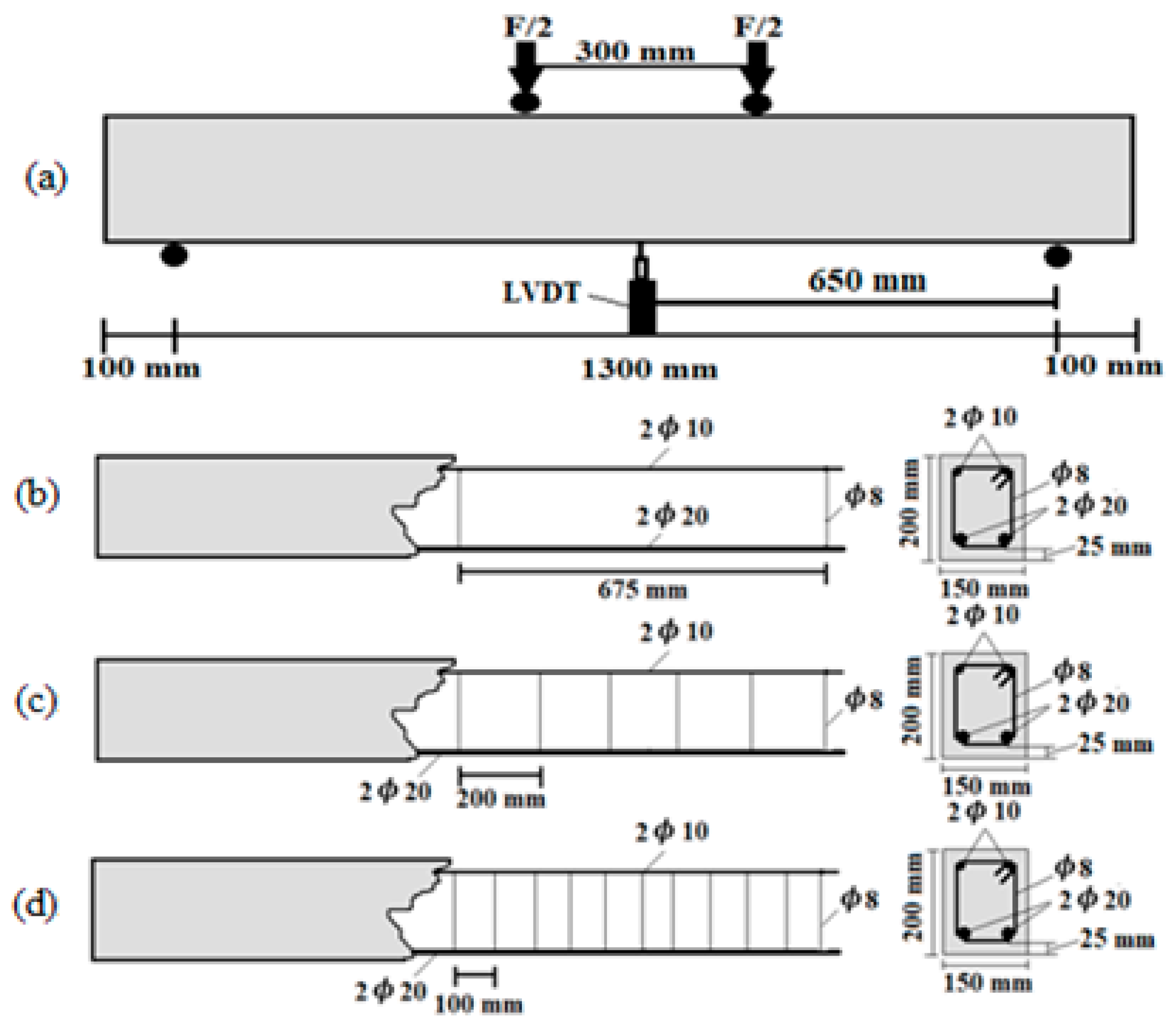
After evaluating the influence of SFs and RCA on the compressive and tensile behaviour of unreinforced concrete, 27 SF-reinforced RCARC beams were produced and measured, where the results are presented in this section. SFs were used at 0%, 1% and 2% (by volume). RCA was incorporated at 0%, 50% and 100% by weight. Furthermore, the effect of shear rebars was considered via different stirrup spacings. The load–displacement behaviour at the mid-span of the specimens, the maximum load-bearing capability and the crack widths and propagation were studied. In Figure 14, Figure 15, Figure 16, Figure 17, Figure 18 and Figure 19, the loading capacity and load-displacement behaviour of the specimens are represented.
As per Figure 14 and 
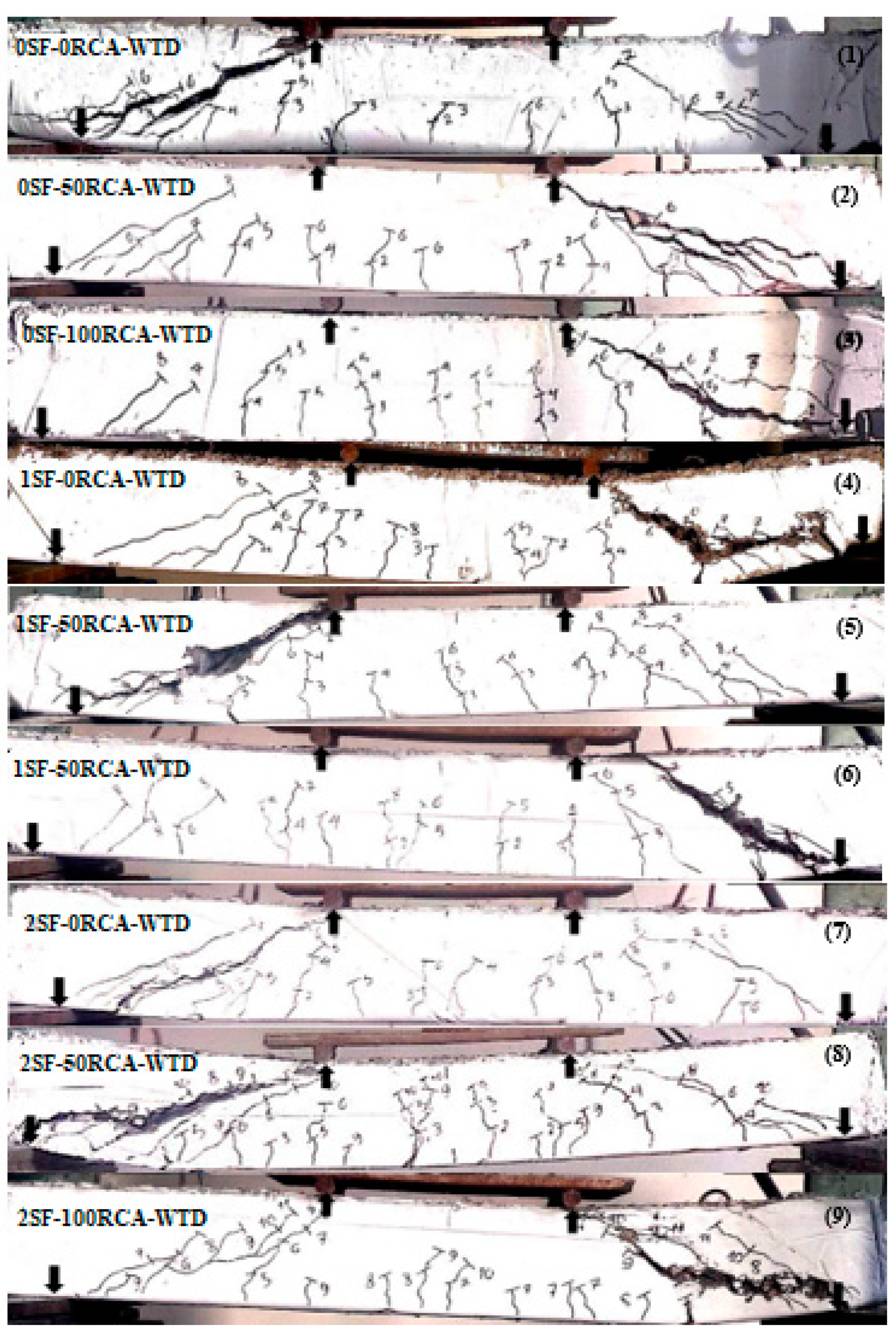
Figure 15, the maximum bearing capability was substantially increased by increasing the SF content due to the effective role of SFs in improving the compressive and tensile strength of the unreinforced concrete. Furthermore, using RCA had a momentous impact on the maximum loading capacity. Furthermore, SFs enhanced the bending resistance strength of concrete due to the lack/insufficiency of shear rebars. Hence, SFs played a role as partial transverse reinforcement and improved the shear performance of the concrete beams. Therefore, the SFs reduced the inclined and shear crack widths and led to improving the first crack loading. As seen in Figure 15, the lack of shear rebars led to shear failure of the specimens but crack propagation increased and the inclined crack widths were reduced by using RCA. Based on the models proposed by several standards, improving the compressive strength of the concrete led to improving the shear behaviour of RC beams. Therefore, according to the results of the compressive behaviour of the unreinforced concrete and the tested beams, RCA was used to produce RC beams without shear reinforcement when 2% SFs were used (Figure 14 and Figure 15).
According to Figure 16 and 
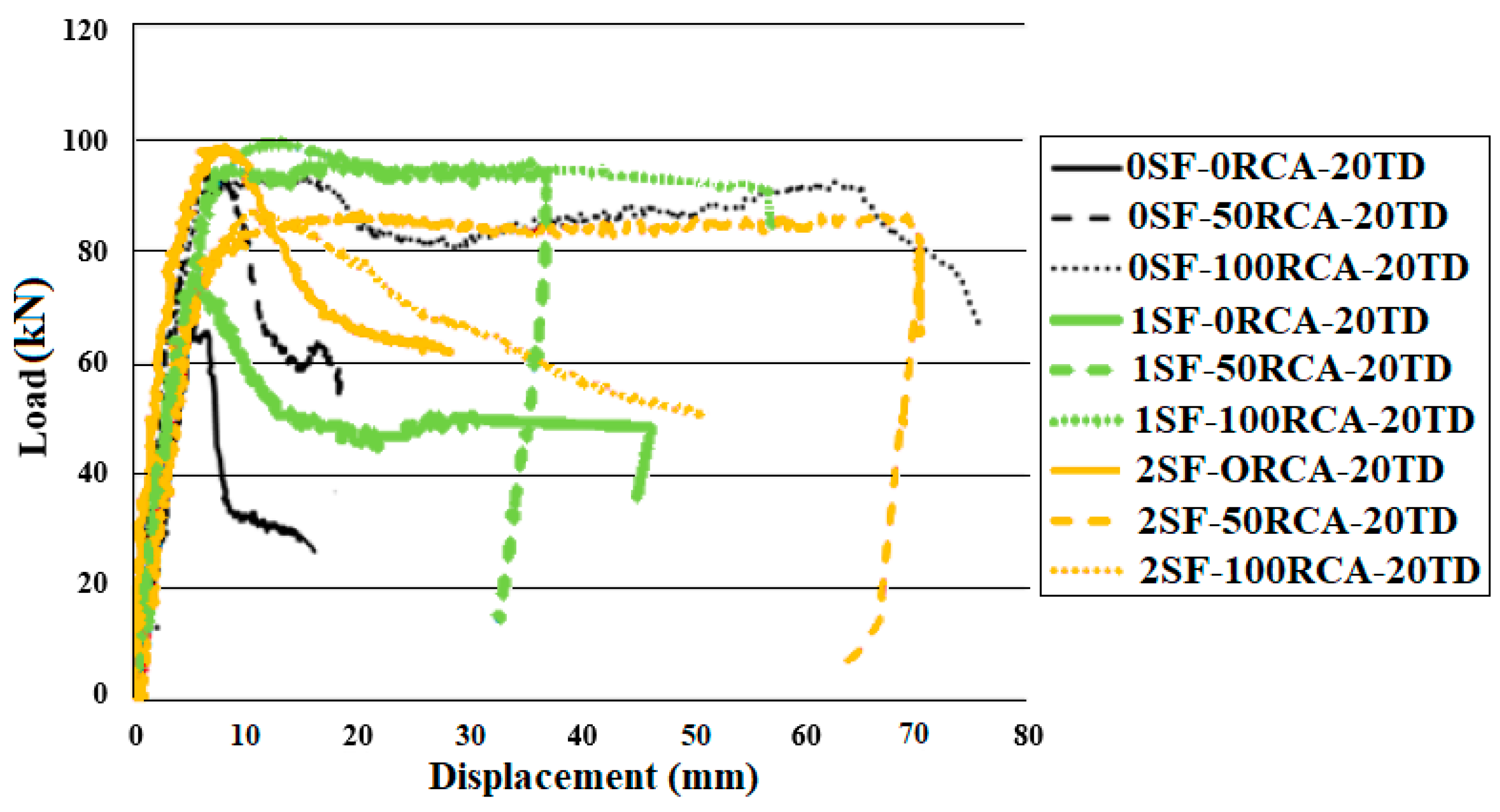
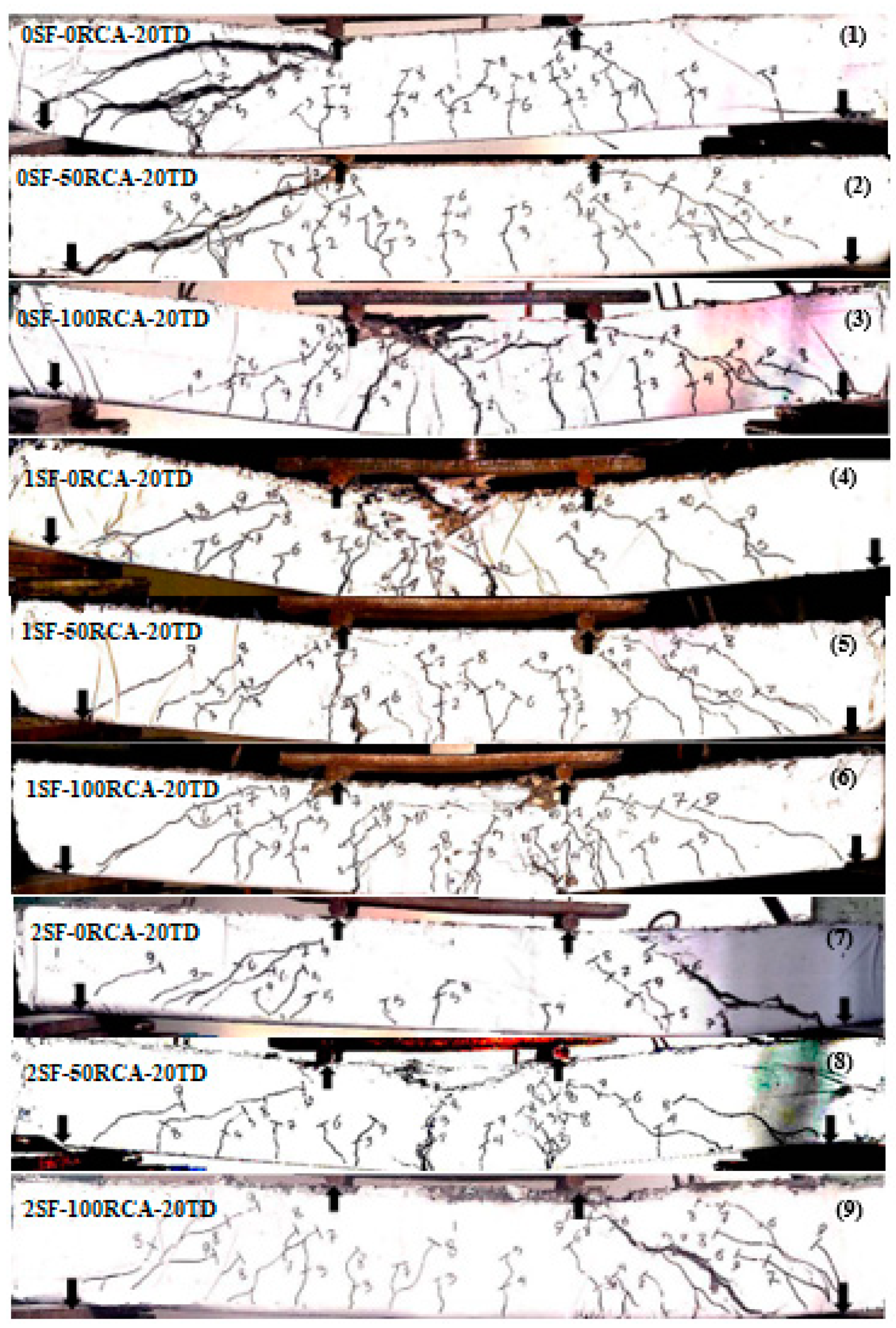
Figure 17, the flexural behaviour improved by providing shear rebars spaced 200 mm apart, which was further enhanced by increasing the RCA content. Conversely, the maximum bearing resistance capacity dropped after the maximum bearing capability point when 100% RCA was used. This led to a dramatically increased crack propagation but the flexural capacity abruptly decreased after the maximum loading point in specimens without RCA. Furthermore, the flexural capacity was increased by utilising SF. Furthermore, reducing the shear rebars’ spacing was necessary. Therefore, enough stirrups should be provided and SFs should be added to the concrete mix.
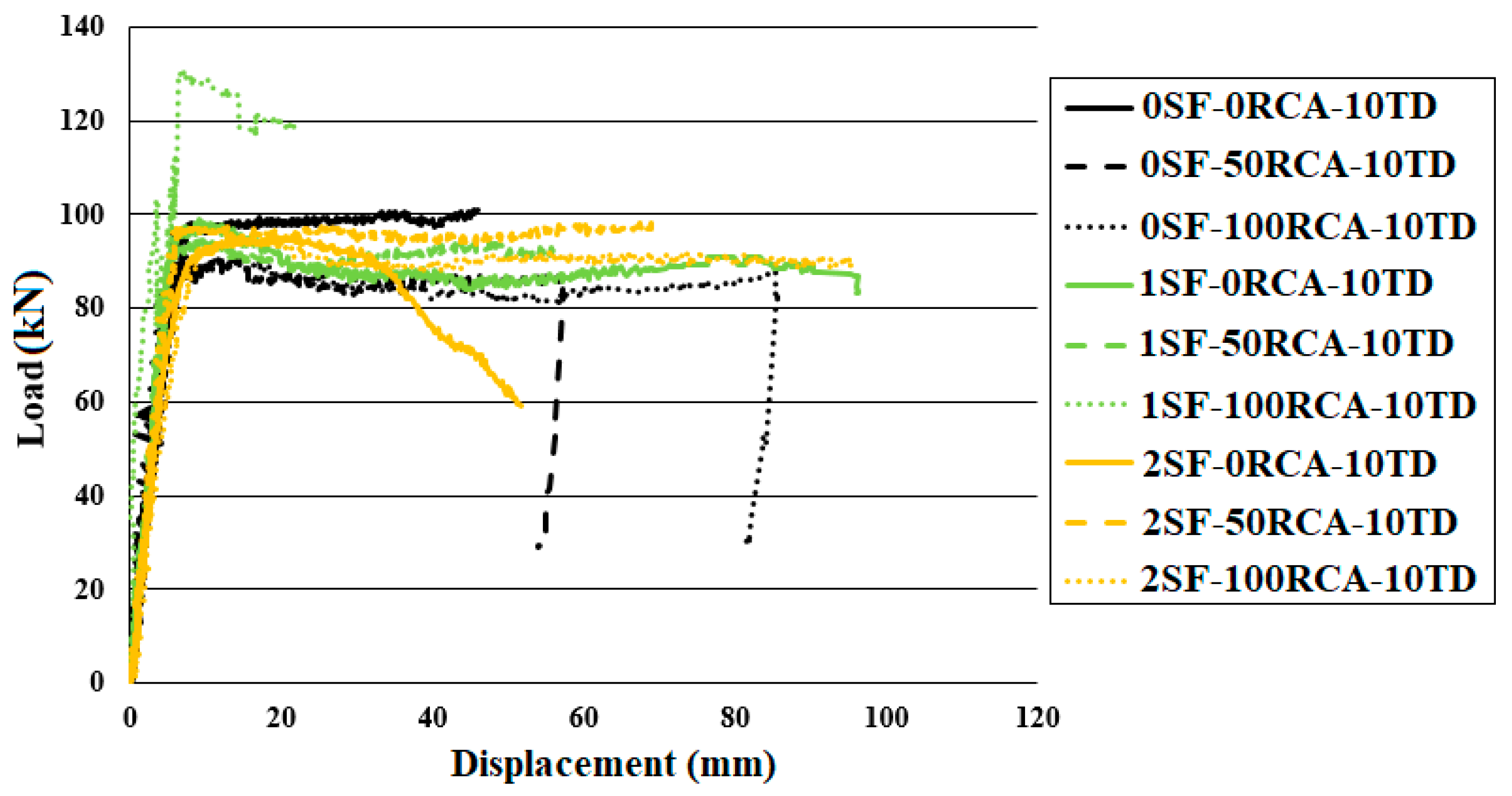
Conversely, reducing the shear rebars’ spacing to 100 mm led to an increase in the bending capability and failure cracks occurred at the middle of the specimen’s width with the maximum spacing (Figure 18 and Figure 19). Adding SFs to concrete improved the bending performance of the specimens as a result of improving the compressive and stress–strain behaviour of the unreinforced concrete. The minimum shear rebars’ spacing should be provided but SFs should be included as well. As it is seen in Figure 18 and Figure 19, NCA could be replaced with RCA at 100% if enough stirrups and SFs are provided in the specimen by comparison with the control specimen (without RCA and SF). According to 
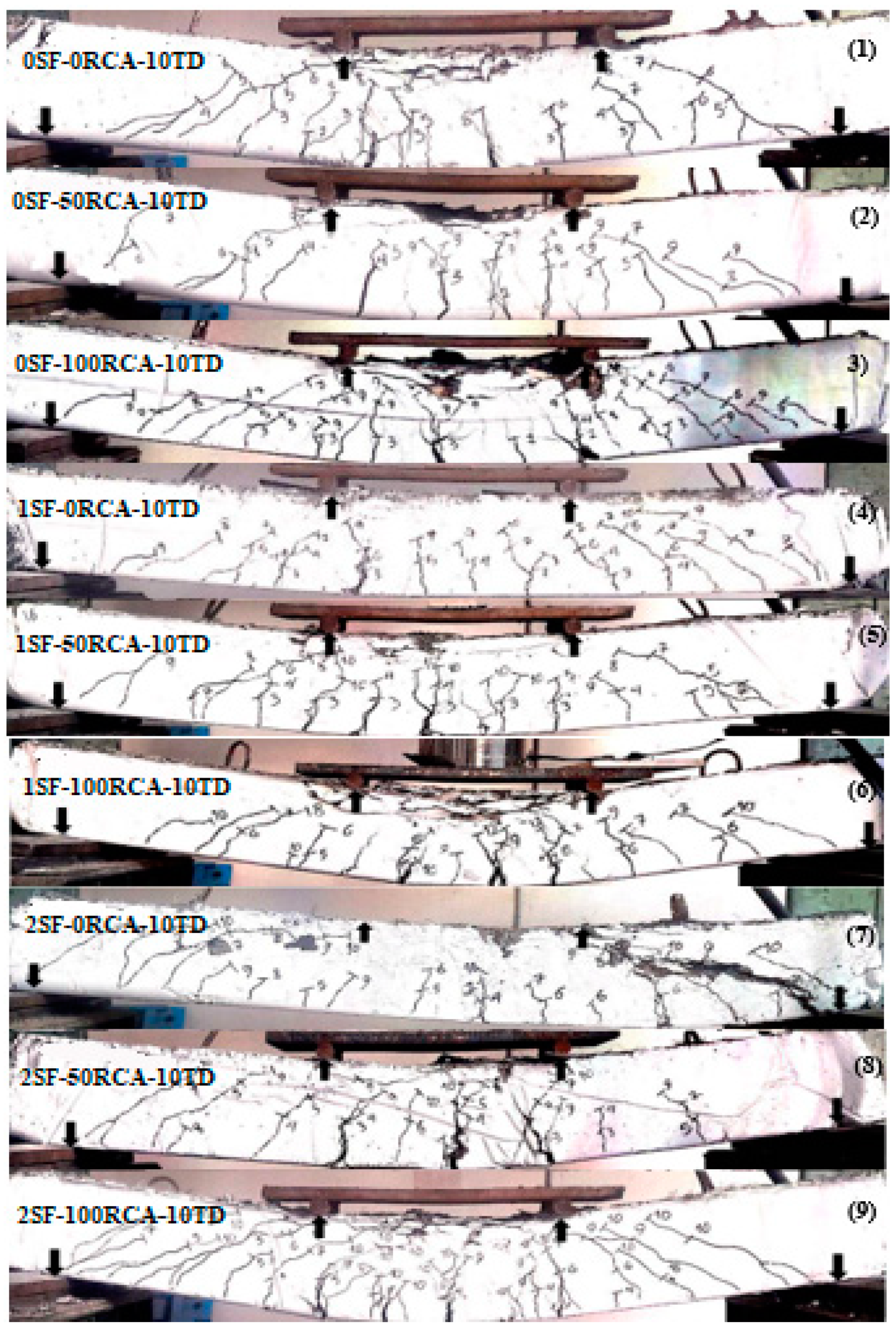
Figure 19, in addition to increasing the bond between the reinforcement and the concrete, cracks developed less when SFs were used due to the bridging role of the SFs. Therefore, specimens with 2% SFs showed greater ductility and did not fail suddenly.
According to Figure 19, reducing shear rebars’ spacing to 100 mm led to dropping the impact of SFs on the bending performance of the RCARC beams. Furthermore, raising the RCA contents generally led to an increased deformation; however, adding SFs did not have a momentous effect on the maximum flexural capability. On the other hand, providing enough shear rebars caused an improvement in the bending performance of specimens. Therefore, crack propagation increased and the crack widths decreased. Furthermore, the first crack loading increased when increasing the RCA content. Hence, using SFs in RC beams that were manufactured with sufficient shear rebars (100 mm spacing) only reduced the crack widths and there was no significant influence of the structural performance of the RC beams. However, when insufficient shear rebars (200 mm spacing) were used, using SFs not only limited the crack widths and their propagation but also improved the structural performance of RC beams.
According to Figure 15, Figure 17 and Figure 19, in addition to increasing the bonding between the rebars and the concrete, cracks developed less after adding SFs due to the bridging role of the fibres and the improvement of the bond-slip between the rebars and the concrete because, with the reduction of the slip between the concrete and rebars, the crack widths were lower. Therefore, specimens with 2% SFs deformed with more ductility and did not collapse abruptly. In specimens with no SFs, the crack propagation was much shorter than in those with SFs. In contrast, in beams with SFs, the final crack spacing corresponding to the stabilised cracking phase was on average 23% smaller than that of the specimens with no SFs. According to these outcomes, it became clear that the formed cracks were consistently much more irregular in beams with SFs than in those without. The crack spacing’s variation ratio ranged from 14 to 39% in beams with no SFs, and from 39 to 46% in specimens with SFs. The relationship between the maximum and average crack spacing was a momentous factor too. This relation was 1.60 in specimens with no SFs and 1.74 in specimens with SFs.
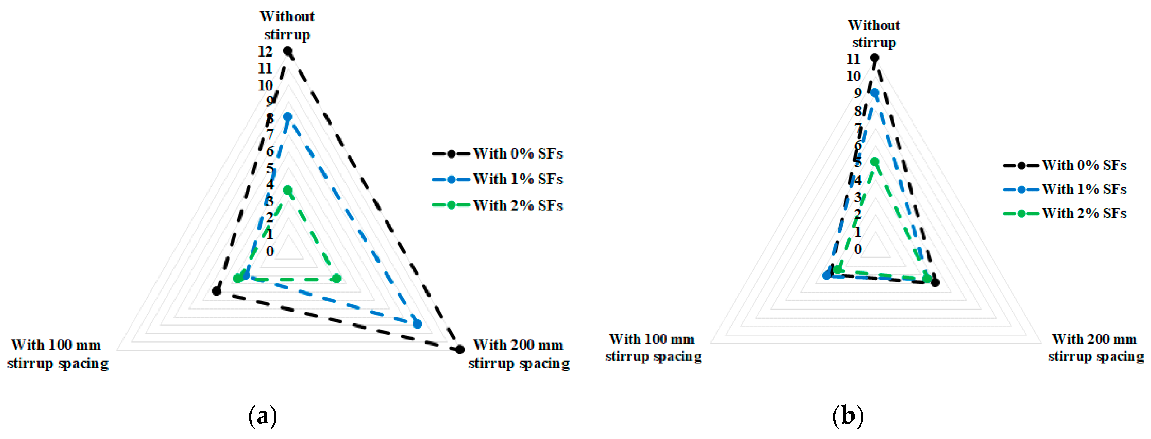
To study the effect of RCA and SF contents as a function of the shear rebars’ spacing, the crack spacing at the peak loads are presented in Table 5 and Figure 20. In Figure 20, the enclosed area of the polygons indicates the influence of the variables on the crack spacing. This means that a reduction of the enclosed area shows a reduction of the crack widths and the positive influence of SFs. Furthermore, in Table 5, the corresponding cracking loads are shown. According to Table 5, using SFs resulted in a considerably decreased crack width at the peak load. Contrariwise, using RCA with more broken surfaces led to a better aggregate bond with cement than using NCA. Therefore, this resulted in reducing the crack widths and increasing the flexural capacity. Providing enough shear rebars along the specimens’ length was essential, especially in specimens with shear cracks, but using SFs could dramatically control the effect of the lack of shear rebars in terms of a reduction in the crack widths. Regarding Figure 20, SFs had a substantial impact on reducing the crack widths at the peak load but there was no significant difference when 1% and 2% SFs were used (Figure 20). Alternatively, using 1% SFs did not have an extensive impact on reducing the crack widths when 100% RCA was used (Figure 20c), but using 2% SFs improved the crack widths in all specimens. According to Figure 20, using 2% SFs significantly reduced the crack widths at the peak load, in contrast to using 1% SFs. Conversely, increasing the RCA content reduced the ultimate crack width reduction effect of SFs.
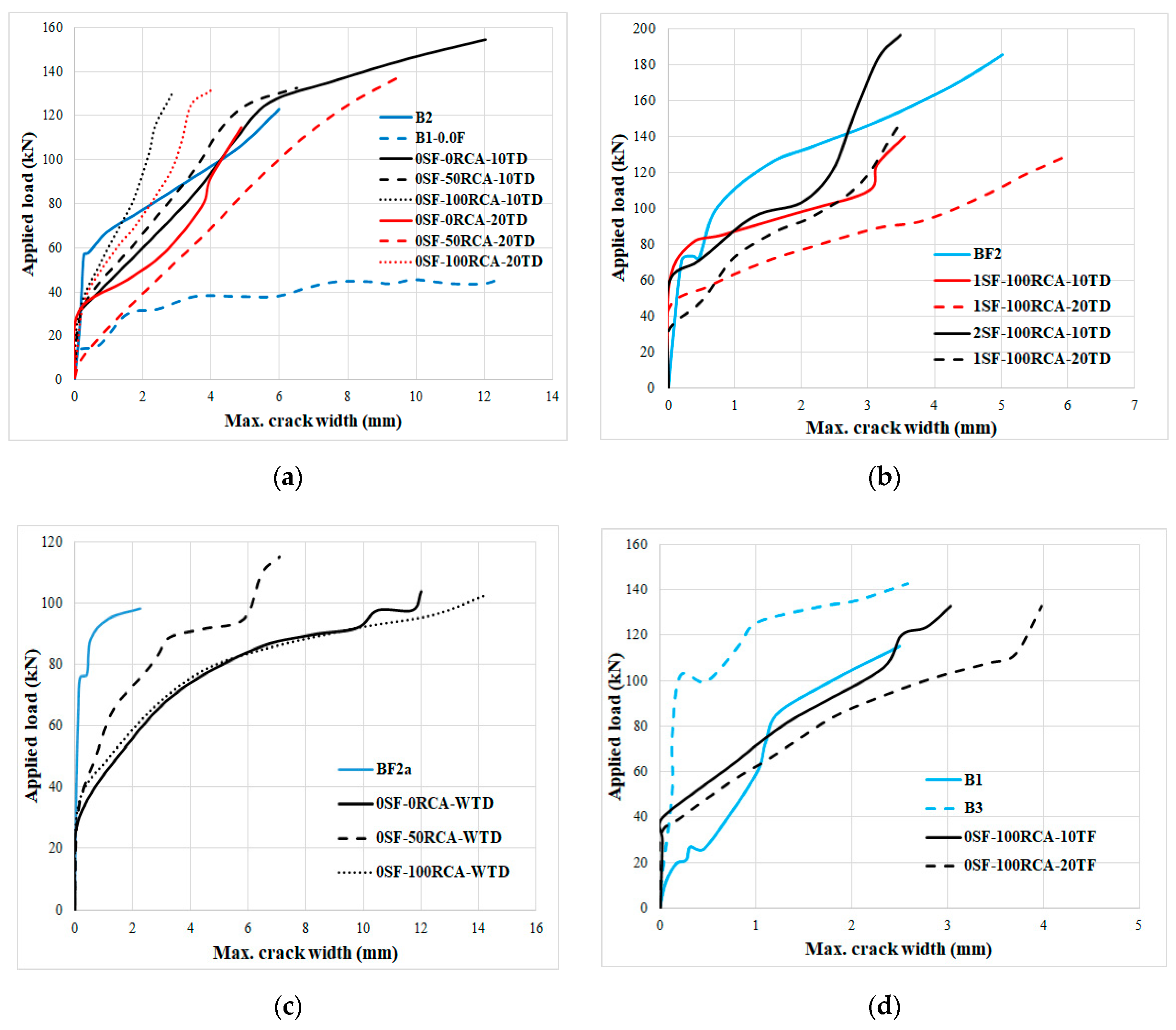
Therefore, the characteristics of these specimens are demonstrated in Table 6. Moreover, in order to provide an accurate analysis, the results were compared with those of the literature and are presented in Figure 21 [59,60].
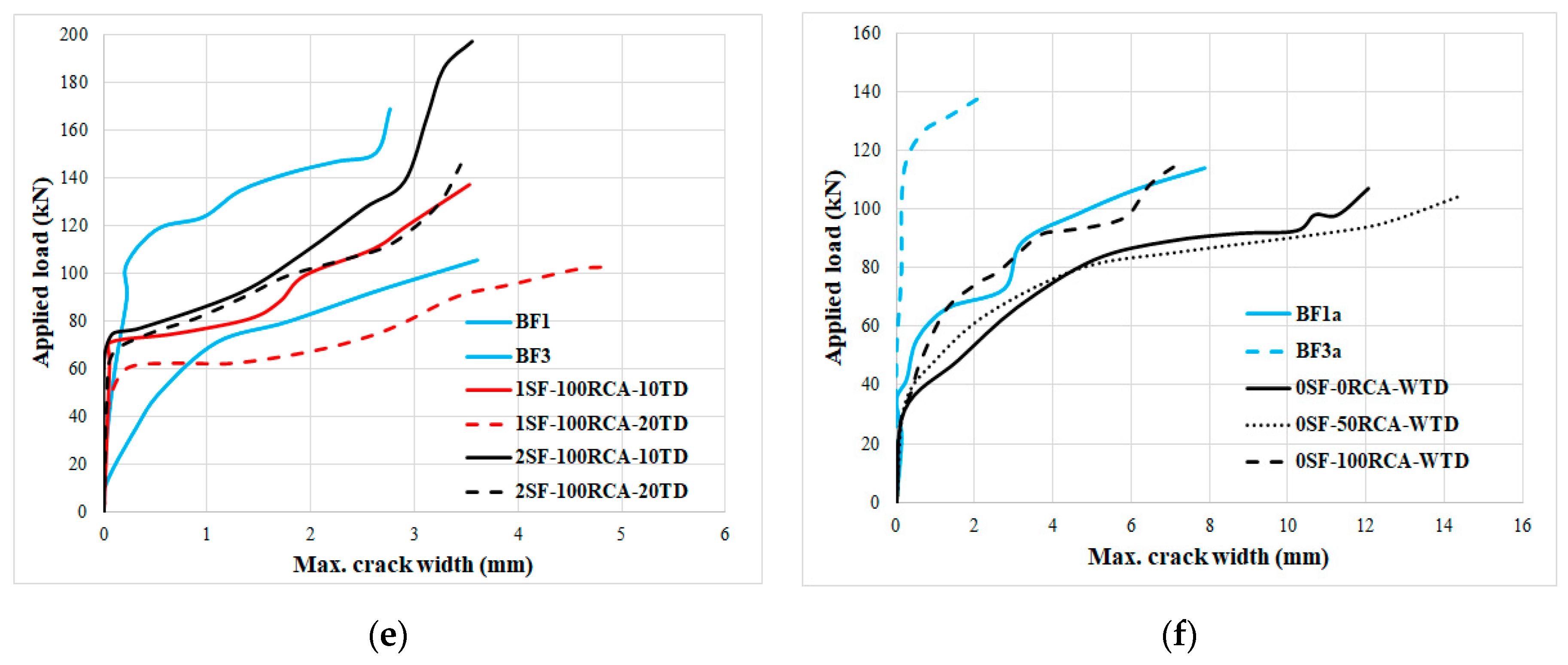
The crack width increased under loading after increasing the shear rebars’ spacing. Furthermore, using RCA resulted in lower crack widths and a greater flexural moment resistance when cracks occurred. Using SFs led to lower flexural crack widths and the flexural strength was also significantly increased after cracks appeared (Figure 21b,e). As seen in Figure 20c and Figure 21f, the flexural crack widths were increased by increasing the tensile rebars’ diameter in the RCARC beams. Furthermore, Figure 21a–d shows that the effect of longitudinal tensile rebars was more than the effect of the shear rebars on the crack widths. Therefore, providing enough shear rebars limited the crack propagation and the crack widths decreased. Furthermore, the crack at the peak load increased due to increasing the RCA contents. Additionally, cracks developed less by adding SFs due to the bridging role of the fibres. However, in specimens with no SFs, the crack propagation was considerably lower than that with SFs. Therefore, it could be observed that the cracks were more irregular in the SF-reinforced beams relative to those of the control specimens (with no SFs or RCA).
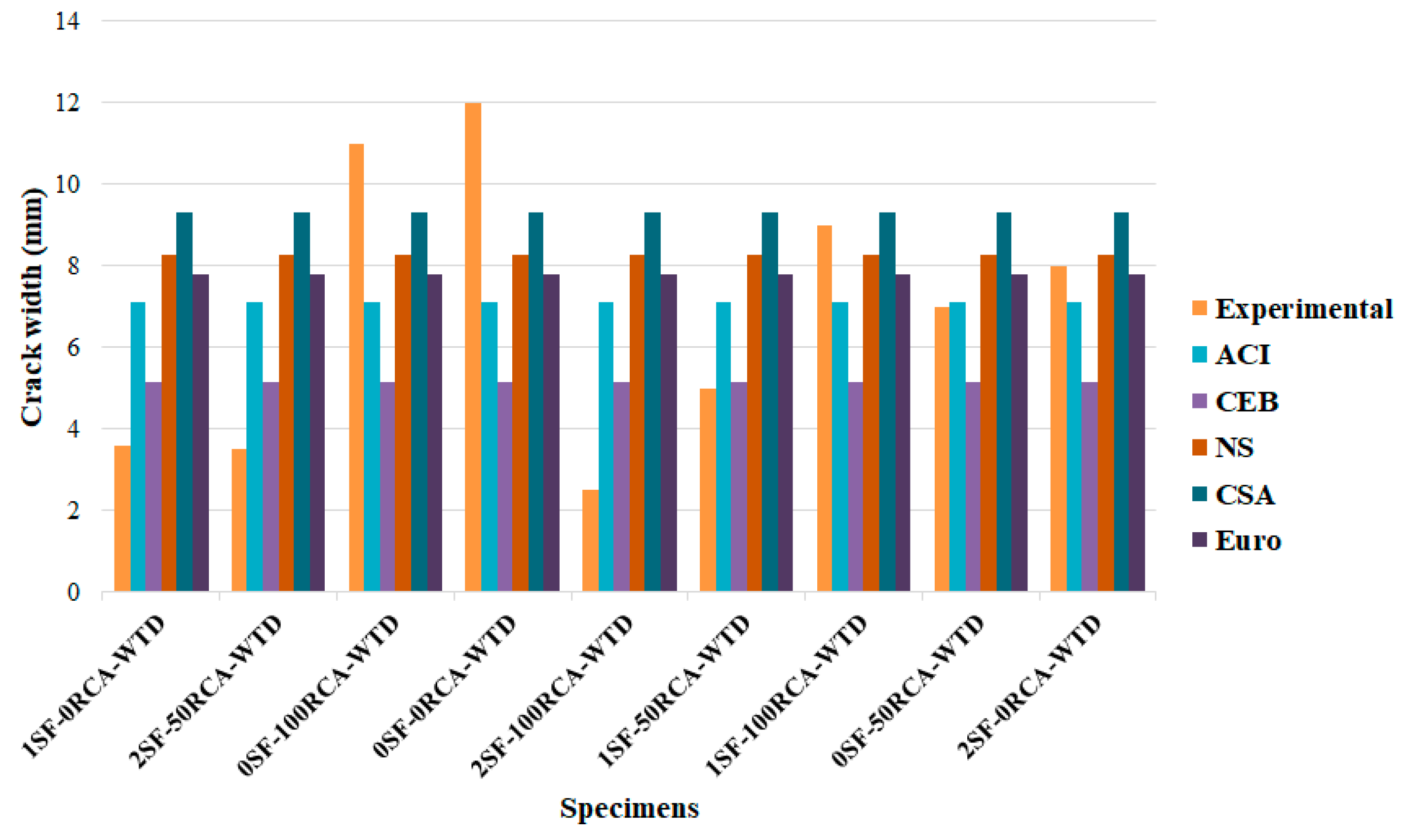
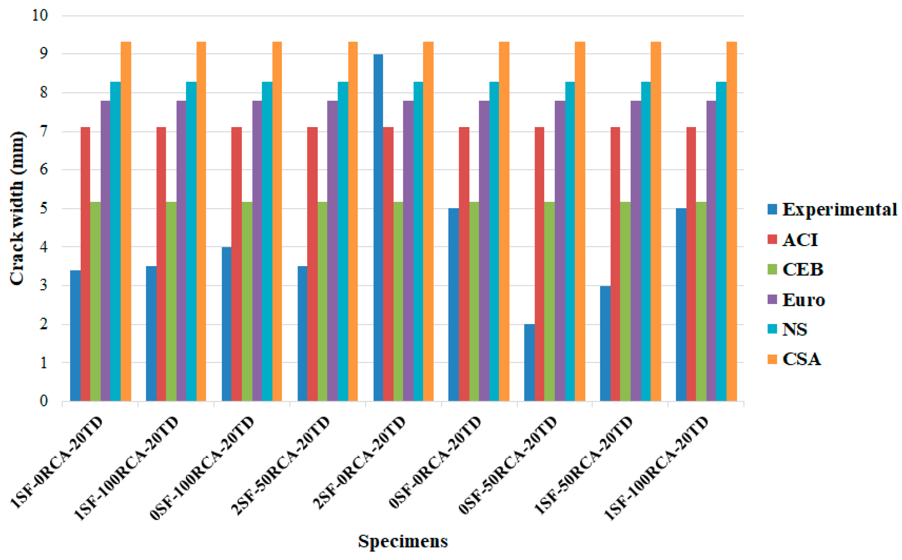
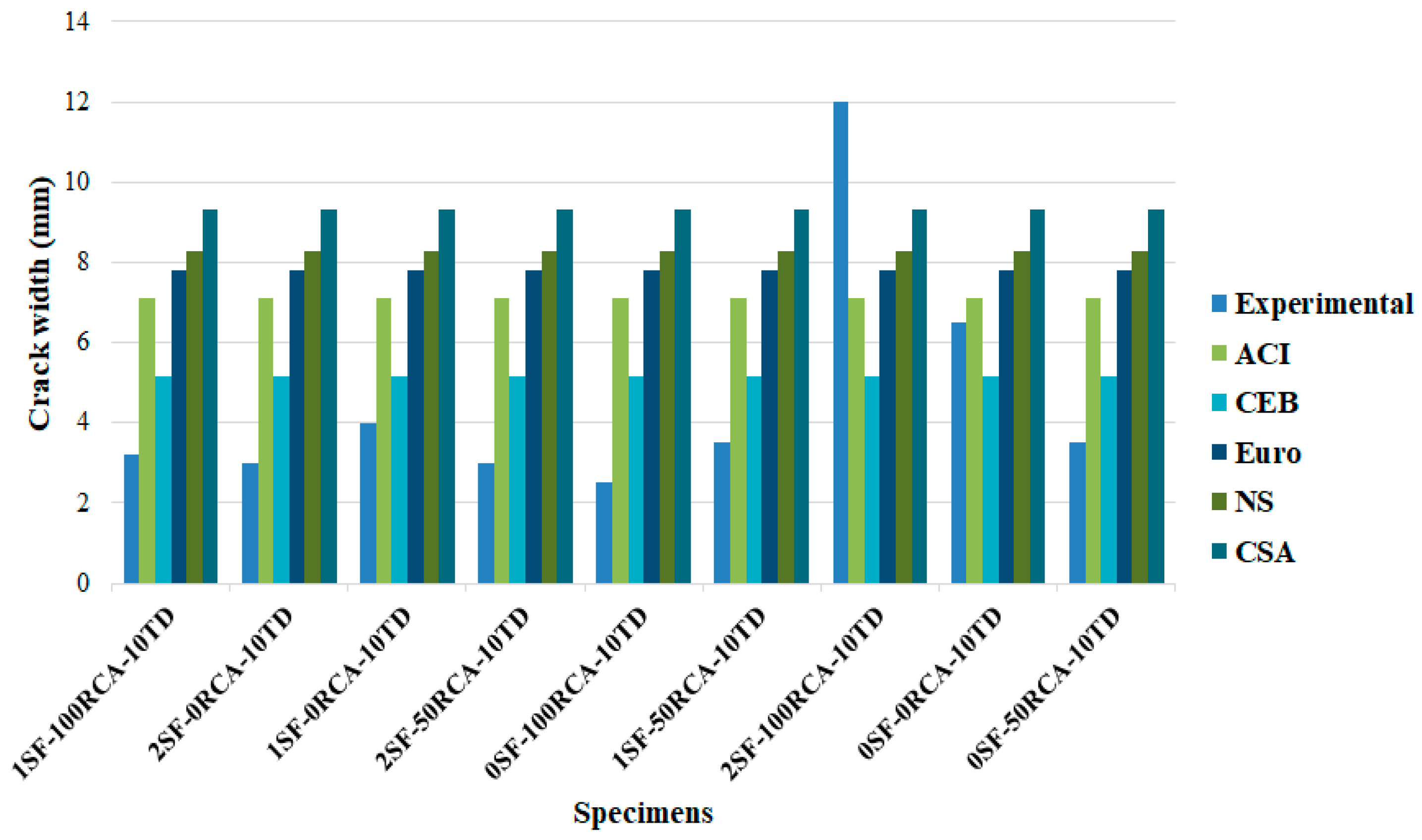
Finally, the results were compared with the requirements of CSA S474 [53], NS 3473E [54], EC2-04 [55], CEB-FIP [56] and ACI 224R-14 [57], where the results are shown in Figure 22, Figure 23 and Figure 24. In specimens with no shear rebars or SFs, the available equations predicted crack widths lower than the obtained results, where crack width was reduced by adding SFs. Furthermore, codes could not predict the crack width when NCA was replaced with RCA, especially for 100% replacement. CSA predicted the crack width properly but CEB predicted inaccurate widths when no SFs were used in the RCARC specimens (the predicted crack widths were less than that obtained numerically). Conversely, in the experimental samples with 200 mm and 100 mm shear rebar spacings, all standards presented appropriate equations regarding predicting the crack width at different SF and RCA contents (Figure 22, Figure 23 and Figure 24). It should be mentioned that CEB properly predicted the crack width in specimens with 200 mm and 100 mm stirrup spacings. Additionally, the obtained experimental results were compared with those achieved based on the requirements of the codes, as illustrated in Table 7.

6. Conclusions

In this research, the impact of SFs on the cracking in RCARC beams was evaluated. The research involved tests on 27 RC beams. In the specimens, SFs were mixed at different contents (0%, 1% and 2%). In the tests, the mid-span load–displacement relationship and the crack propagation and widths were measured. The obtained laboratory results were also compared with the proposed equations of CSA S474 (2004), NS 3473E (2003), EC2-04 (2004), CEB-FIP (2010) and ACI 224R-14 (2014). According to the achieved outcomes, the following conclusions could be drawn:
  • RCA is an appropriate material that can be used instead of natural materials in concrete for buildings.
  • The bending capability increased by increasing the RCA content. Additionally, using 100% RCA decreased the load drop after the maximum bearing capability point, while in the specimen without RCA, the bending resistance abruptly dropped after the maximum load.
  • SFs enhanced the maximum bearing capability and using this material with RCA enhanced the flexural resistance of the RCARC beams compared to the control specimens.
  • Enough shear rebars must be provided over the beams to control the crack width and propagation but SFs can enhance the bending performance of RCARC beams without shear rebars.
  • In addition to increasing the bonding between the rebars and concrete, cracks developed less when SFs were used. Therefore, specimens with a 2% SF content deformed with more ductility and did not collapse quickly.
  • Adding SFs to concrete improved the bending performance of the specimens. A minimum number of shear rebars should be provided but SFs should be used in the specimens.
  • In specimens with no shear rebars, CSA properly predicted the crack width, unlike CEB. On the other hand, all codes presented an appropriate equation to predict crack width in specimens with different SF and RCA contents.
  • In cylindrical specimens under pressure, by adding SFs, cracking occurred only in the concrete surface. Furthermore, due to RCA’s higher and more angulated specific surface compared to NCA, RCA was better impregnated with cement paste, which prevented the complete disintegration of the sample.
  • In cylindrical specimens under indirect tensile stresses, a specimen with no SFs broke into two parts but using SFs prevented them from separating. The use of RCA increased the tensile strength of the specimen.
  • SFs had a significant effect on reducing the initial crack’s width but there was no significant difference when 1% and 2% SFs were used. On the other hand, using 1% SFs did not have a considerable effect on reducing the initial crack’s width when 100% RCA were used.

Author Contributions

Conceptualization, M.G. and J.d.B.; Formal analysis, M.G.; Investigation, A.K. and H.R.C.; Methodology, A.K. and H.R.C.; Software, M.G.; Supervision, M.G. and J.d.B.; Writing–original draft, A.K. and H.R.C.; Writing–review & editing, J.d.B. All authors have read and agreed to the published version of the manuscript.

Funding

This research received no external funding.

Acknowledgments

The authors wish to thank the CERIS (Civil Engineering Research and Innovation for Sustainability) research centre and the FCT (Foundation for Science and Technology).

Conflicts of Interest

The authors declare that they have no conflict of interest.

Data Availability

The raw/processed data required to reproduce these findings cannot be shared at this time as the data also forms part of an ongoing study.

Notation

A c t effective concrete cross-sectional area
A s t outer area of the tension rebars layer
bcross-sectional width
Cconcrete cover
deffective depth
d b diameter of the rebars
E S elasticity modulus of the steel rebars
f c concrete compressive resistance
f y yield strength of the steel rebars
k 2 strain coefficient
l s ، m a x length of the tension rebars’ slip
NCAnatural coarse aggregate
RCreinforced concrete
RCArecycled coarse aggregate;
RCARCrecycled coarse aggregate reinforced concrete;
Sdepth of the outer reinforcement layer
SFssteel fibres
S m average distance between the cracks
S m ، C S A average crack distance according to CSA S474 2004;
TDshear rebars’ spacing
W k ، E C 2 design crack spacing
ε 1 highest effective strain in the tensioned area
ε 2 lowest effective strain in the tensioned area
ε c s free shrinkage strain of concrete
ε s r 2 rebars’ stress in the cracks under equivalent load f c t m
ρ t N S effective reinforcement ratio.

References

  1. Hu, B.; Wu, Y.F. Quantification of shear cracking in reinforced concrete beams. Eng. Struct. 2017, 147, 666–678. [Google Scholar] [CrossRef]
  2. Schanack, F.; Ramos, Q.R.; Reyes, J.P.; Low, A.A. Experimental study on the influence of concrete cracking on timber-concrete composite beams. Eng. Struct. 2015, 84, 362–367. [Google Scholar] [CrossRef]
  3. Chen, H.; Yi, W.J.; Hwang, H.J. Cracking strut-and-tie model for shear strength evaluation of reinforced concrete deep beams. Eng. Struct. 2018, 163, 396–408. [Google Scholar] [CrossRef]
  4. Hu, H.T.; Chou, T.F. Strengthening of BWR Mark III reinforced concrete containment with fibre composite laminate material. Int. J. Press. Vessels Pipingm. 2002, 79, 297–308. [Google Scholar] [CrossRef]
  5. Gail, S.; Kolluru, V.; Subramaniam, L. Investigation of the dilatant behaviour of cracks in the shear response of steel fibre reinforced concrete beams. Eng. Struct. 2017, 152, 832–842. [Google Scholar] [CrossRef]
  6. Pahlavan, L.; Zhang, F.; Blacquière, G.; Yang, Y.; Hordijk, D. Interaction of ultrasonic waves with partially-closed cracks in concrete structures. Constr. Build. Mater. 2018, 167, 899–906. [Google Scholar] [CrossRef]
  7. Kuang, K.S.C.; Goh, T.W.K. Crack sensing and healing in concrete beams based on wire-crack sensors and healing tube. Constr. Build. Mater. 2017, 132, 395–411. [Google Scholar] [CrossRef]
  8. Ghahremannejad, M.; Mahdavi, M.; Saleh, A.E.; Abhaee, S.; Abolmaali, A. Experimental investigation and identification of single and multiple cracks in synthetic fibre concrete beams. Case Stud. Constr. Mater. 2018, 9, e00182. [Google Scholar] [CrossRef]
  9. Karimipour, A.; Esfahani, M.R. The Effect of Steel Fibers on Flexural Cracking of Fiber in Reinforced Concrete Beams with Lap-spliced Bars. Ferdowsi Univ. J. Civ. Eng. 2018, 31. [Google Scholar] [CrossRef]
  10. Luo, D.; Yue, Y.; Li, P.; Ma, J.; Ismail, Z. Concrete beam crack detection using tapered polymer optical fibre sensors. Measurement 2016, 88, 96–103. [Google Scholar] [CrossRef]
  11. Ramos, I.S.; Aït-Salem Duque, O.; De Merodio, M.H.G.; Pozhilova, N. Cracking study of a reinforced concrete beam. Procedia Struct. Integr. 2016, 1, 257–264. [Google Scholar] [CrossRef] [Green Version]
  12. Wosatko, A.; Genikomsou, A.; Pamin, J.; Polak, M.A.; Winnicki, A. Examination of two regularized damage-plasticity models for concrete with regard to crack closing. Eng. Fract. Mech. 2018, 194, 190–211. [Google Scholar] [CrossRef]
  13. Ghalehnovi, M.; Karimipour, A.; de Brito, J. Influence of steel fibres on the flexural performance of reinforced concrete beams with lap-spliced bars. Constr. Build. Mater. 2019, 229, 116853. [Google Scholar] [CrossRef]
  14. Siad, A.; Bencheikh, M.; Hussein, L. Effect of combined pre-cracking and corrosion on the method of repair of concrete beams. Constr. Build. Mater. 2017, 132, 462–469. [Google Scholar] [CrossRef]
  15. Arora, S.; Singh, S.P. Analysis of flexural fatigue failure of concrete made with 100% coarse recycled concrete aggregates. Constr. Build. Mater. 2016, 102, 782–791. [Google Scholar] [CrossRef]
  16. Choi, W.C.; Yun, H.D. Long-term deflection and flexural behaviour of reinforced concrete beams with recycled aggregate. Mater. Des. 2013, 51, 742–750. [Google Scholar] [CrossRef]
  17. Azad, A.M. Flexural behavior and analysis of reinforced concrete beams made of recycled PET waste concrete. Constr. Build. Mater. 2017, 155, 593–604. [Google Scholar]
  18. Gao, D.; Zhang, L. Flexural performance and evaluation method of steel fiber reinforced recycled coarse aggregate concrete. Constr. Build. Mater. 2018, 159, 126–136. [Google Scholar] [CrossRef]
  19. Seara-Paz, S.; González-Fonteboa, B.; Martínez-Abella, F.; Eiras-López, J. Flexural performance of reinforced concrete beams made with recycled concrete coarse aggregate. Eng. Struct. 2018, 156, 32–45. [Google Scholar] [CrossRef]
  20. Tošic’, N.; Marinkovic, S.; Ignjatovic, I. A database on flexural and shear strength of reinforced recycled aggregate concrete beams and comparison to Eurocode 2 predictions. Constr. Build. Mater. 2016, 127, 932–944. [Google Scholar] [CrossRef]
  21. Tarek, T.M.; Das, H.K.; Mahmood, A.H.; Rahman, M.N.; Awal, M.A. Flexural performance of RC beams made with recycled brick aggregate. Constr. Build. Mater. 2017, 134, 67–74. [Google Scholar]
  22. Zaetanga, Y.; Sata, V.; Wongsa, A.; Chindaprasir, P. Properties of pervious concrete containing recycled concrete block aggregate and recycled concrete aggregate. Constr. Build. Mater. 2016, 111, 15–21. [Google Scholar] [CrossRef]
  23. Karimipour, A.; Ghalehnovi, M.; de Brito, J. The effect of polypropylene fibres on the compressive strength impact and heat resistance of self-compacting concrete. Structures 2020, 25, 72–87. [Google Scholar] [CrossRef]
  24. Alyousef, R.; Topper, T.; Al-Mayah, A. Crack growth modelling of tension lap spliced reinforced concrete beams strengthened with fibre reinforced polymer wrapping under fatigue. Constr. Build. Mater. 2018, 166, 345–355. [Google Scholar] [CrossRef]
  25. Li, C.Q.; Yang, S.T. Prediction of concrete crack spacing under combined reinforcement corrosion and applied load. J. Eng. Mech. 2011, 137, 722–731. [Google Scholar] [CrossRef] [Green Version]
  26. Karimipour, A.; Edalati, M. Shear and flexural performance of low. Normal and high-strength concrete beams reinforced with longitudinal SMA, GFRP and steel rebars. Eng. Struct. 2020, 221, 111086. [Google Scholar]
  27. Cai, J.Y.; Liu, Y.Y.; Wang, X.L.; Xiong, J.L.; Wan, H.X.; Tu, Z.F. Comparative study on crack spacing prediction for concrete flexural members with GFRP reinforcement. Adv. Mater. Res. 2011, 64, 971–992. [Google Scholar] [CrossRef]
  28. Xu, Q.; Huang, W.; Wu, H.Z.; Wang, J.Y.; Liu, J.Y. Study of the crack spacing of the fibre reinforced polymer beam. Adv. Mater. Res. 2011, 59, 806–827. [Google Scholar] [CrossRef]
  29. Karimipour, A.; Edalati, M. Influence of untreated coal and recycled aggregates on the mechanical properties of green concrete. J. Clean. Prod. 2020, 276, 124291. [Google Scholar] [CrossRef]
  30. Rezaiee-Pajand, M.; Karimipour, A.; Mohebi Najm Abbadi, J. Crack Spacing Prediction of Fibre-Reinforced Concrete Beams with Lap-Spliced Bars by Machine Learning Models. Iran. J. Sci. Technol. Trans. Civ. Eng. 2020, 20, 12–30. [Google Scholar]
  31. Piyasena, R.; Loo, Y.C.; Fragomeni, S. Determination of crack spacing and crack spacing in reinforced concrete beams. Struct. Eng. Mech. 2003, 15, 159–180. [Google Scholar] [CrossRef]
  32. Rezaiee-Pajand, M.; Rezaiee-Pajand, A.; AMohebi Najm Abbadi, J.A. Particle Swarm optimization algorithm to suggest formulas for the behaviour of the recycled materials reinforced concrete beams. Int. J. Optim. Civ. Eng. 2020, 10, 451–479. [Google Scholar]
  33. Chaboki, M.R.; Ghalehnovi, M.; Karimipour, A.; de Brito, J. Experimental study on the flexural behaviour and ductility ratio of steel fibres coarse recycled aggregate concrete beams. Constr. Build. Mater. 2018, 186, 400–422. [Google Scholar] [CrossRef]
  34. Okabayashi, T.; Okumatsu, T.; Koba, T.; Nakamura, H. Concrete crack and spacing detecting by high-resolution-digital devices. Rep. Fac. Eng.—Nagasaki. Univ. 2003, 33, 143–158. [Google Scholar]
  35. Karimipour, A.; Ghalehnovi, M.; de Brito, J. Mechanical and durability properties of steel fibre-reinforced rubberised concrete. Constr. Build. Mater. 2020, 257, 119463. [Google Scholar] [CrossRef]
  36. Farokhpour Tabrizi, M.; Ghalehnovi, M.; Karimipour, A. Investigation of the effect of steel fibers on failure extension of recycled aggregate concrete beams with lap-spliced bars. Sharif J. Civ. Eng. 2019, 18. [Google Scholar] [CrossRef]
  37. Elshafey, A.A.; Dawood, N.; Marzouk, H.; Haddara, M. Predicting of crack spacing for concrete by using neural networks. Eng. Fail. Anal. 2013, 31, 344–359. [Google Scholar] [CrossRef]
  38. Anvari, A.; Ghalehnovi, M.; de Brito, J.; Karimipour, A. Improved bending behaviour of steel fibres recycled aggregate concrete beams with a concrete jacket. Mag. Concr. Res. 2019, 20, 35–51. [Google Scholar]
  39. Farokhpour Tabrizi, M.; Ghalehnovi, M.; Karimipour, A. Effect of Polypropylene Fibers on the Recycled Aggregate Concrete. In Proceedings of the 6th National Conference on Applied Research in Civil Engineering, Architecture and Urban Management and 5th Conference & Specialized Exhibition on Tehran mass Producers, Tehran, Iran, 10 December 2019. [Google Scholar]
  40. Mahmod, M.; Hanoon, A.N.; Abed, H.J. Flexural behaviour of self-compacting concrete beams strengthened with steel fibre reinforcement. J. Build. Eng. 2018, 16, 228–237. [Google Scholar] [CrossRef]
  41. Yoo, D.Y.; Yang, J.M. Effects of the stirrup, steel fibre, and beam size on shear behaviour of high-strength concrete beams. Cem. Concr. Compos. 2018, 87, 137–148. [Google Scholar] [CrossRef]
  42. Zhang, F.; Ding, Y.; Xu, J.; Zhang, Y.; Shi, Y. Shear strength prediction for steel fibre reinforced concrete beams without stirrups. Eng. Struct. 2016, 127, 101–116. [Google Scholar] [CrossRef]
  43. Kim, D.J.; Naaman, A.E.; El-Tawil, S. Comparative flexural behaviour of four fibre reinforced cementitious composites. Cem. Concr. Compos. 2008, 30, 917–928. [Google Scholar] [CrossRef]
  44. Altun, F.; Aktas, B. Investigation of reinforced concrete beams behaviour of steel fibre added lightweight concrete. Constr. Build. Mater. 2013, 38, 575–581. [Google Scholar] [CrossRef]
  45. Yoo, D.Y.; Yoon, Y.S.; Banthia, N. Predicting the post-cracking behaviour of normal- and high-strength steel-fibre-reinforced concrete beams. Constr. Build. Mater. 2015, 93, 477–485. [Google Scholar] [CrossRef]
  46. Mertol, H.C.; Baran, E.; Jibril Bello, H. Flexural behaviour of lightly and heavily reinforced steel fibre concrete beams. Constr. Build. Mater. 2015, 98, 185–193. [Google Scholar] [CrossRef]
  47. Patil, S.P.; Single, K.K. Tests of steel fibre reinforced concrete beams under predominant torsion and bending. J. Build. Eng. 2016, 6, 157–162. [Google Scholar] [CrossRef]
  48. Luccioni, B.; Isla, F.; Codina, R.; Ambrosini, D.; Zerbino, R.; Giaccio, G.; Torrijos, M.C. Effect of steel fibres on static and blast response of high strength concrete. Int. J. Impact Eng. 2017, 107, 23–37. [Google Scholar] [CrossRef] [Green Version]
  49. Lee, J.Y.; Shin, H.O.; Yoo, D.Y.; Yoon, Y.S. Structural response of steel-fibre-reinforced concrete beams under various loading rates. Eng. Struct. 2018, 156, 271–283. [Google Scholar] [CrossRef]
  50. Guo, Y.; Zhang, J.; Chen, G.; Xie, Z. Compressive behaviour of concrete structures incorporating recycled concrete aggregates rubber crumb and reinforced with steel fibre, subjected to elevated temperatures. J. Clean. Prod. 2014, 72, 193–203. [Google Scholar] [CrossRef]
  51. Carneiro, J.A.; Lima, P.R.L.; Leite, M.B.; Filho, R.D. Compressive stress-strain behaviour of steel fibre reinforced-recycled aggregate concrete. Cem. Concr. Compos. 2014, 46, 65–72. [Google Scholar] [CrossRef]
  52. Chaboki, M.R.; Ghalehnovi, M.; Karimipour, A.; de Brito, J.; Khatibinia, M. Shear behaviour of concrete beams with recycled aggregate and steel fibres. Constr. Build. Mater. 2019, 204, 809–827. [Google Scholar] [CrossRef]
  53. Canadian Standard Associations. S474 Concrete Structures; Canadian Standard Associations: Mississauga, ON, Canada, 2004. [Google Scholar]
  54. Norwegian Council for Building Standardization. NS 3473E, Concrete Structures Design Rules; Norwegian Council for Building Standardization: Oslo, Norway, 2003. [Google Scholar]
  55. EC2; Eurocode 2. Design of Concrete Structures—Part I: General Rules and Rules for Buildings; Committee for Standardization: Paris, France, 2004. [Google Scholar]
  56. Comité Euro Internationale du Béton and Fédération Internationale de la Précontrainte. CEB-FIP Model Code 2010; Comité Euro Internationale du Béton and Fédération Internationale de la Précontrainte: Lausanne, Switzerland, 2010. [Google Scholar]
  57. ACI Committee 224R-14. Control of cracking in concrete structures reported by ACI Committee 224-2001: 17-21. Structures 2014, 163, 396–408. [Google Scholar] [CrossRef]
  58. Chaboki, M.R.; Ghalehnovi, M.; Karimipour, A. Investigation of flexural behavior of concrete beams made of recycled aggregate. Concr. Res. Q. J. 2019, 10, 45–68. [Google Scholar] [CrossRef]
  59. Randic, J.; Markota, L.M.; Haraptin, A. Numerical model for crack spacing calculation in concrete elements. Struct. Eng. Int. 2006, 16, 59–65. [Google Scholar] [CrossRef]
  60. Wiesława, G.; Marek, Z. Cracking behaviour of steel fiber reinforced waste sand concrete beams in flexure—Experimental investigation and theoretical analysis. Eng. Struct. 2018, 176, 1–10. [Google Scholar] [CrossRef]
Figure 1. Thickness of the buried area according to CSA-S474-2044 [53].
Applsci 10 07587 g001
Figure 2. Calculation of the effective area to determine the flexural crack spacing, according to NS 3473E 2003 [54].
Applsci 10 07587 g002
Figure 3. The effective area [55].
Applsci 10 07587 g003
Figure 4. Determination of A, d c and S to calculate the flexural crack spacing according to ACI 224R-01 [57].
Applsci 10 07587 g004
Figure 5. Recycled coarse aggregate (RCA).
Applsci 10 07587 g005
Figure 6. Natural coarse aggregate (NCA).
Applsci 10 07587 g006
Figure 7. Grading curve of the aggregates employed in the current investigation.
Applsci 10 07587 g007
Figure 8. Type and dimension of the SFs used in this study.
Applsci 10 07587 g008
Figure 9. Geometry of the beams and arrangement of the rebars: (a) boundary condition, (b) specimen without transverse reinforcement, (c) specimens with a 200 mm transverse reinforcement spacing and (d) specimens with a 100 mm transverse reinforcement spacing. (Note: LVDT: Linear variable differential transformer).
Applsci 10 07587 g009
Figure 10. Test setup: (a) four-point bending test of the beams and the (b) compressive stress–strain setup.
Applsci 10 07587 g010
Figure 11. Effects of the SF and RCA contents on the concrete’s compressive behaviour.
Applsci 10 07587 g011
Figure 12. Effects of the SF and RCA contents on the concrete’s tensile behaviour.
Applsci 10 07587 g012aApplsci 10 07587 g012b
Figure 13. Stress–strain curves of the specimens (a) with no RCA, (b) 50% RCA and (c) 100% RCA.
Applsci 10 07587 g013aApplsci 10 07587 g013b
Figure 14. Bending behaviour of the specimens with various SF and RCA contents and no shear rebars. WTD: without transverse reinforcement.
Applsci 10 07587 g014
Figure 15. Failure and crack propagation of the specimens without a stirrup.
Applsci 10 07587 g015
Figure 16. Bending behaviour of specimens with various SF and RA contents and 200 mm shear rebars’ spacing. 20TD: transverse reinforcement spacing 200 mm.
Applsci 10 07587 g016
Figure 17. Failure and crack propagation in specimens with a 200 mm shear rebar spacing.
Applsci 10 07587 g017
Figure 18. Bending behaviour of specimens with various S values and RCA contents and a 100 mm shear rebar spacing.
Applsci 10 07587 g018
Figure 19. Failure in specimens with 100 mm stirrup spacing and crack propagation.
Applsci 10 07587 g019
Figure 20. Effect of SFs on the maximum crack widths for (a) 0% RCA, (b) 50% RCA and (c) 100% RCA.
Applsci 10 07587 g020aApplsci 10 07587 g020b
Figure 21. Applied load–crack width performance of specimens with various SF and RA contents (a) specimens without SF with different RCA contents, (b) specimens with different SF contents and 100% RCA, (c) specimens without SF and stirrup, (d) specimens without SF and with 100% RCA, (e) specimens with different SF contents, 100 RCA and different stirrup spacing and (f) specimens without fibres and stirrup with different RCA contents.
Applsci 10 07587 g021aApplsci 10 07587 g021b
Figure 22. Observed versus predicted ultimate crack width of specimens without shear rebars.
Applsci 10 07587 g022
Figure 23. Observed versus predicted ultimate crack widths of specimens with a 200 mm shear rebar spacing.
Applsci 10 07587 g023
Figure 24. Observed versus predicted ultimate crack width of specimens with a 100 mm shear rebar spacing.
Applsci 10 07587 g024
Table 1. Physical and chemical properties of RCA and NCA.
Physical PropertiesAggregate Type
NCARCA
Apparent density (g/cm3)2.82.7
Bulk density (g/cm3)2.72.6
Water absorption (wt%)1.441.19
Crush index (%)30.0048.9
Porosity (%)3.93.88
Table 2. Concrete mixes’ compositions and strengths.
Specimens0SF-0RCA0SF-50RCA0SF-100RCA1SF-0RCA1SF-50RCA1SF-100RCA2SF-0RCA2SF-50RCA2SF-100RCA
Water (kg/m3)165165165165165165165165165
Cement (kg/m3)400400400400400400400400400
SFs (kg/m3)000787878156156156
RCA (kg/m3)042084003857650345685
NCA (kg/m3)840420076538506853450
NFA (kg/m3)950950950950950950950950950
Average tensile stress (MPa)3.784.294.045.006.124.105.014.684.99
Tensile stress coefficient of variation0.170.040.090.010.270.040.270.090.13
Average compressive resistance (MPa)38.435.037.136.835.735.736.935.735.6
Compressive strength coefficient of variation1.561.081.651.331.190.851.381.000.78
NFA: natural fine aggregates, SFs: steel fibres. The number before SF refers to the percentage by volume of steel fibres, while the number before the RCA refers to the percentage of recycled coarse aggregate by mass.
Table 3. Rebar test results.
PropertiesResults
Rebar diameter (mm)81020
Yield stress (MPa)370410370
Ultimate stress (MPa)560680560
Yield strain (%)13.013.015.3
Ultimate strain (%)25.025.425.9
Modulus of elasticity (GPa)209.3210.10213.2
Table 4. Stress-strain formulas for different SF reinforced RCARC.
SpecimensFormula R 2
0SF-0RCA y = 1 × 10 7 x 2 + 40269 x 0.37 0.9838
1SF-0RCA y = 9 × 10 6 x 2 + 35670 x 0.19 0.9959
2SF-0RCA y = 2 × 10 6 x 2 + 18183 x + 2.85 0.9429
0SF-50RCA y = 3 × 10 7 x 2 + 22481 x + 5.28 0.8862
1SF-50RCA y = 1 × 10 7 x 2 + 47581 x 0.28 0.9839
2SF-50RCA y = 3 × 10 6 x 2 + 20805 x + 2.63 0.9574
0SF-100RCA y = 3 × 10 7 x 2 + 69316 x + 1.75 0.9921
1SF-100RCA y = 2 × 10 7 x 2 + 47953 x + 1.75 0.9921
2SF-100RCA y = 4 × 10 6 x 2 + 25425 x + 4.88 0.9492
Table 5. Cracking and load corresponding to crack occurrences.
SpecimensLoading of First Crack Occurrence (kN)Specimen’s Failure Load (kN)Crack Widths at the Peak Load (mm)Mode of Failure
0SF-0RCA-WTD20.070.012.0Shear
0SF-0RCA-20TD20.280.112.0Shear
0SF-0RCA-10TD20.690.55.0Flexural
0SF-50RCA-WTD20.170.27.0Shear
0SF-50RCA-20TD20.290.16.5Shear
0SF-50RCA-10TD20.690.72.0Flexural
0SF-100RCA-WTD20.180.011.0Shear
0SF-100RCA-20TD30.490.04.0Flexural
0SF-100RCA-10TD20.890.53.0Flexural
1SF-0RCA-WTD20.280.18.0Shear
1SF-0RCA-20TD20.8100.09.0Flexural
1SF-0RCA-10TD30.2100.63.5Flexural
1SF-50RCA-WTD10.180.25.0Shear
1SF-50RCA-20TD20.090.63.0Flexural
1SF-50RCA-10TD20.695.42.5Flexural
1SF-100RCA-WTD20.080.19.0Shear
1SF-100RCA-20TD20.6100.23.5Flexural
1SF-100RCA-10TD40.4100.93.2Flexural
2SF-0RCA-WTD20.280.03.6Shear
2SF-0RCA-20TD40.490.03.4Shear
2SF-0RCA-10TD40.8100.53.5Flexural
2SF-50RCA-WTD20.090.14.0Shear
2SF-50RCA-20TD20.190.73.5Flexural
2SF-50RCA-10TD20.6100.33.5Flexural
2SF-100RCA-WTD30.090.15.0Shear
2SF-100RCA-20TD40.2100.53.5Shear
2SF-100RCA-10TD50.5110.22.5Flexural
Table 6. Characteristics of the various specimens.
Series NumberBeamsDimensions (mm)Tensile Reinforcement (mm)Stirrups (mm)Volume Fraction (%)
1B1150 × 200 × 15002#8#6@125---
BF1150 × 200 × 15002#8#6@1251
BF1a150 × 200 × 15002#8---1
2B2150 × 200 × 15002#12#6@125---
BF2150 × 200 × 15002#12#6@1251
BF2a150 × 200 × 15002#12---1
3B3150 × 200 × 15002#16#6@125---
BF3150 × 200 × 15002#16#6@1251
BF3a150 × 200 × 15002#16---1
4B1-0.0F150 × 200 × 1500#3#3@127---
# and @ indicates the size of transverse rebars and their spacing, respectively, e.g. #6@125 means stirrups with diameter of 6 mm with 125 mm spacing.
Table 7. Comparison between the numerical and experimental results of the crack widths.
Specimens W A C I W e x p W C E B F I P W e x p W E u r o W e x p W N S W e x p W C S A W e x p
1SF-100RCA-10TD2.2208151.612632.433322.5849922.911027
1SF-0RCA-20TD2.0901791.5177692.2901842.4329342.73979
1SF-0RCA-WTD1.9740581.4334492.1629512.2977712.58758
1SF-100RCA-20TD2.0304591.4744042.224752.3634212.66151
2SF-0RCA-10TD2.3688691.7201382.5955412.7573253.105096
2SF-50RCA-WTD2.0304591.4744042.224752.3634212.66151
1SF-0RCA-10TD2.0304591.4744042.224752.3634212.66151
0SF-100RCA-WTD0.6460550.4691290.7078750.7519980.846844
2SF-50RCA-10TD1.7766521.2901041.9466562.0679942.328822
0SF-100RCA-20TD1.7766521.2901041.9466562.0679942.328822
2SF-50RCA-20TD2.0304591.4744042.224752.3634212.66151
0SF-100RCA-10TD2.3688691.7201382.5955412.7573253.105096
0SF-0RCA-WTD0.5922170.4300350.6488850.6893310.776274
2SF-0RCA-20TD0.7896230.5733790.865180.9191081.035032
0SF-0RCA-20TD1.4213221.0320831.5573251.6543951.863057
1SF-50RCA-10TD2.8426432.0641663.114653.308793.726115
2SF-100RCA-WTD2.8426432.0641663.114653.308793.726115
0SF-50RCA-20TD3.5533042.5802083.8933124.1359874.657643
1SF-50RCA-20TD2.3688691.7201382.5955412.7573253.105096
1SF-50RCA-WTD1.4213221.0320831.5573251.6543951.863057
1SF-100RCA-WTD0.7896230.5733790.865180.9191081.035032
0A-50RCA-WTD1.015230.7372021.1123751.1817111.330755
2SF-100RCA-10TD2.0304591.4744042.224752.3634212.66151
2SF-0RCA-WTD0.8883260.6450520.9733281.0339971.164411
2SF-100RCA-20TD1.4213221.0320831.5573251.6543951.863057
0SF-0RCA-10TD0.5922170.4300350.6488850.6893310.776274
0SF-50RCA-10TD1.0933240.793911.1979421.2726111.433121
Note: The subscripts on the Ws in the numerators denote the standards being assessed, while the exp subscript refers to the experimental value.
Publisher’s Note: MDPI stays neutral with regard to jurisdictional claims in published maps and institutional affiliations.

