Robust LQR Control for PWM Converters with Parameter-Dependent Lyapunov Functions


Abstract
:1. Introduction
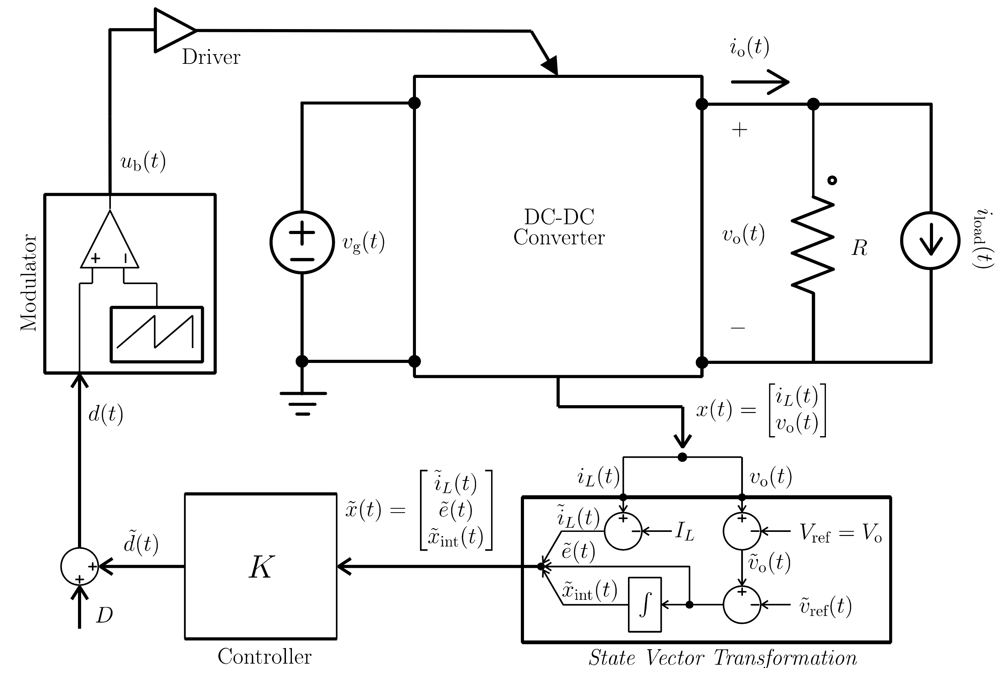
2. Modeling of the DC–DC Converter and LQR State Feedback Control
2.1. Averaged Model of the DC–DC Boost Converter
2.2. Previous LMI Formulation of the LQR Synthesis Problem
3. New Formulation of the LQR Problem for Linear Parameter-Varying (LPV) Polytopic Systems
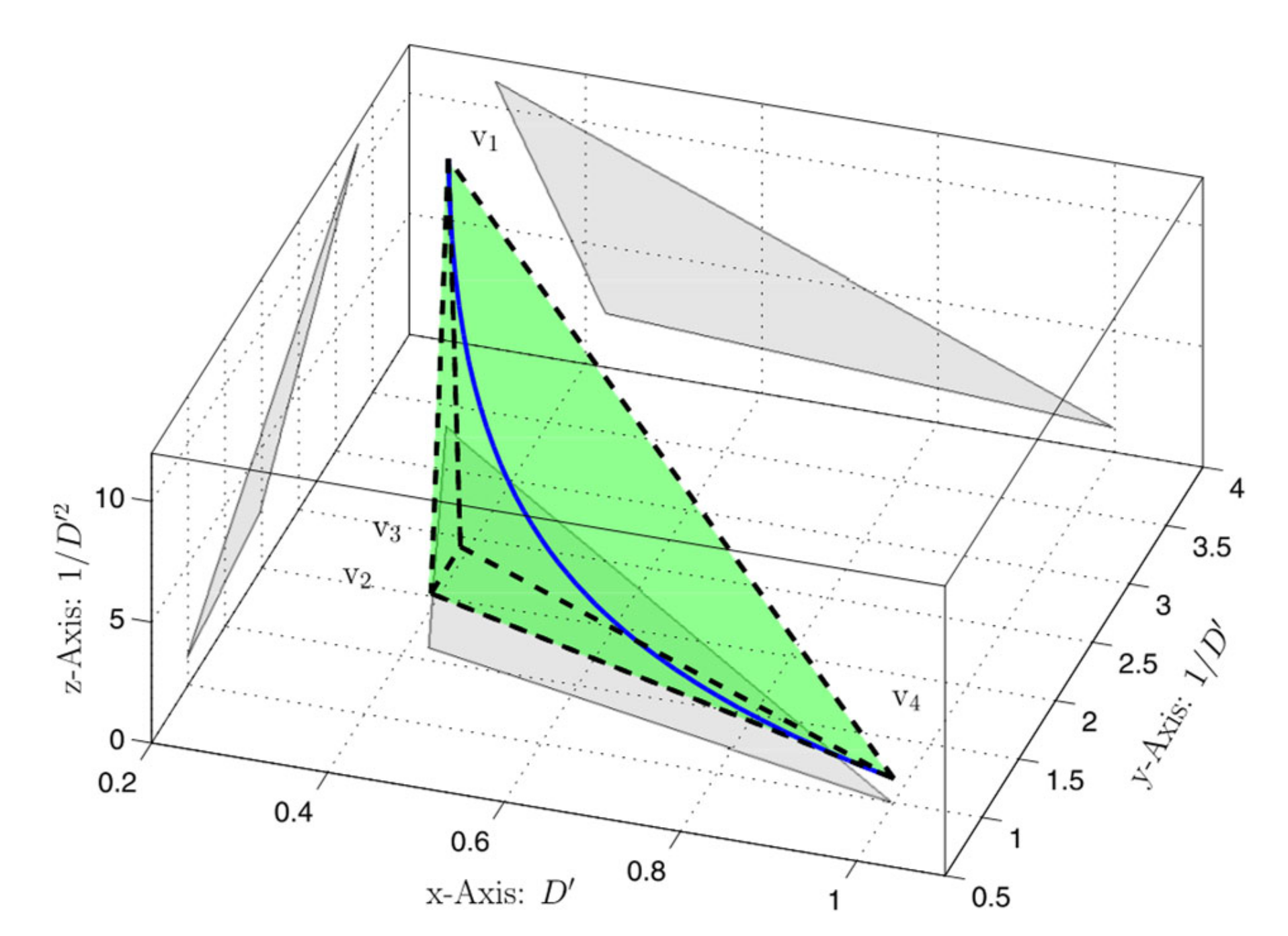
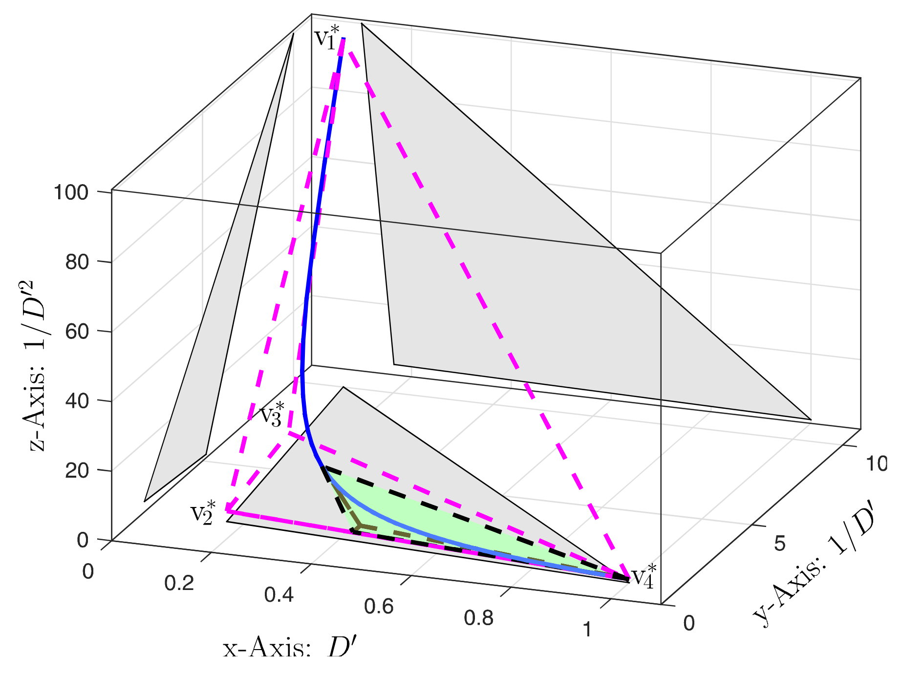
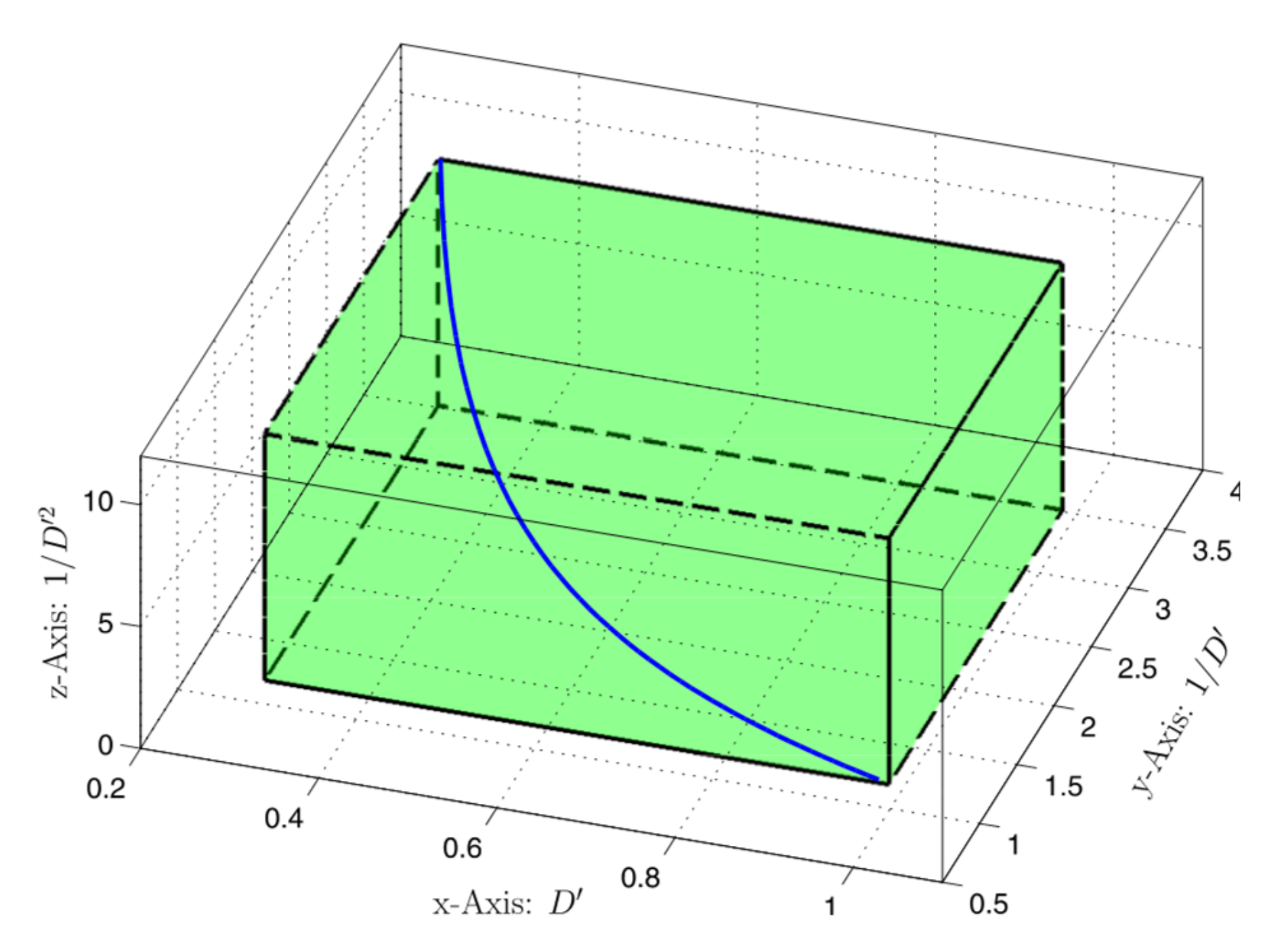
3.1. Proposed Representation of Uncertainty and Its Rate of Variation
3.2. New LQR Problem Formulation for Uncertain LPV System
4. Synthesis of Improved LQR Controllers for DC–DC Boost Converters
4.1. Modeling
4.2. Synthesis Results
4.2.1. Previous LQR Synthesis Method
- −
- With :.
- −
- With : The set of LMIs is infeasible.
- −
- With : The set of LMIs is infeasible.
4.2.2. Proposed LQR Synthesis Method
- −
- With , b = 1·104, α = 1·105, R = 1·10-6, the result is .
- −
- With , b = 1·104, α = 1·105, R = 1·10-6, the result is .
- −
- With , b = 1·104, α = 1·105, R = 1·10-5, the result is .
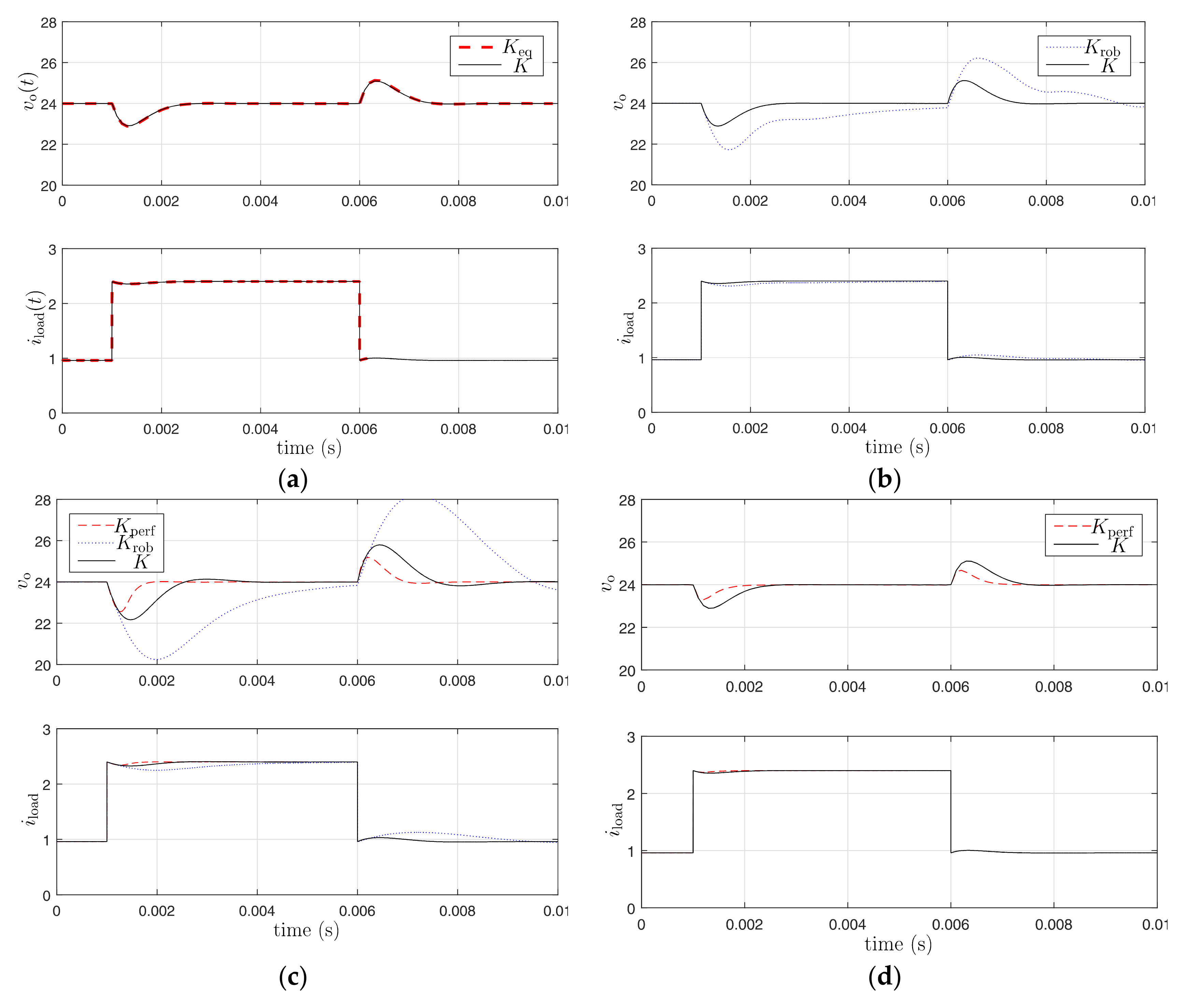
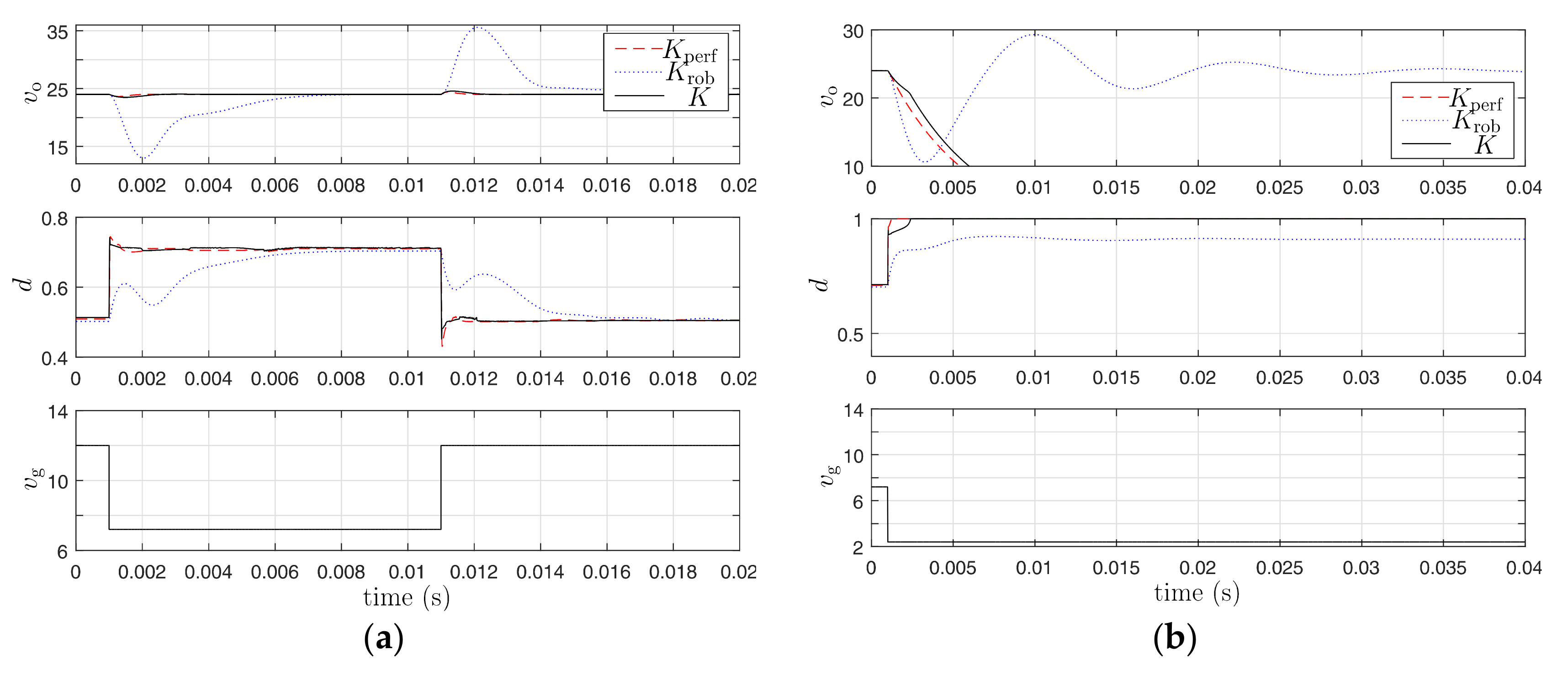
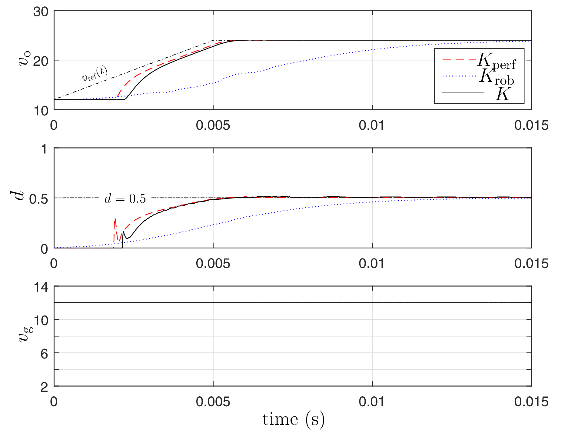
5. Simulation Results
6. Conclusions
Author Contributions
Funding
Conflicts of Interest
References
- Middlebrook, R.D.; Ćuk, S. A general unified approach to modelling switching-converter power stages. Int. J. Electron. 1977, 42, 521–550. [Google Scholar] [CrossRef]
- Erickson, R.W.; Maksimović, D. Fundamentals of Power Electronics; Springer: Cham, Switzerland, 2001. [Google Scholar]
- Deisch, C. Simple switching control method changes power converter into a current source. IEEE Power Electron. Spec. Conf. 1978, 300–306. [Google Scholar] [CrossRef]
- Capel, A.; Ferrante, G.; O’Sullivan, D.; Weinberg, A. Application of the injected current model for the dynamic analysis of switching regulators with the new concept of LC3 modulator. IEEE Power Electron. Spec. Conf. 1978, 135–147. [Google Scholar] [CrossRef]
- Montagner, V.; Peres, P. Robust pole location for a DC-DC converter through parameter dependent Control In Proceedings of the 2003 International Symposium on Circuits and Systems, ISCAS 2003. Bangkok, Thailand, 25–28 May 2003; Volume 3, pp. 351–354. [Google Scholar]
- Olalla, C.; Leyva, R.; el Aroudi, A.; Garces, P.; Queinnec, I. LMI robust control design for boost PWM converters. IET Power Electron. 2010, 3, 75. [Google Scholar] [CrossRef]
- Olalla, C.; Leyva, R.; el Aroudi, A.; Queinnec, I. Robust LQR Control for PWM Converters: An LMI Approach. IEEE Trans. Ind. Electron. 2009, 56, 2548–2558. [Google Scholar] [CrossRef]
- Gabe, I.J.; Montagner, V.F.; Pinheiro, H. Design and Implementation of a Robust Current Controller for VSI Connected to the Grid Through an LCL Filter. IEEE Trans. Power Electron. 2009, 24, 1444–1452. [Google Scholar] [CrossRef]
- Olalla, C.; Queinnec, I.; Leyva, R.; el Aroudi, A. Optimal State-Feedback Control of Bilinear DC–DC Converters With Guaranteed Regions of Stability. IEEE Trans. Ind. Electron. 2011, 59, 3868–3880. [Google Scholar] [CrossRef]
- Maccari, L.A.; Massing, J.R.; Schuch, L.; Rech, C.; Pinheiro, H.; Oliveira, R.C.L.F.; Montagner, V.F. LMI-Based Control for Grid-Connected Converters With LCL Filters Under Uncertain Parameters. IEEE Trans. Power Electron. 2013, 29, 3776–3785. [Google Scholar] [CrossRef]
- Albea-Sanchez, C.; Garcia, G. Robust hybrid control law for a boost inverter. Control Eng. Pr. 2020, 101, 104492. [Google Scholar] [CrossRef]
- Sferlazza, A.; Albea-Sanchez, C.; Garcia, G. A hybrid control strategy for quadratic boost converters with inductor currents estimation. Control Eng. Pr. 2020, 103, 104602. [Google Scholar] [CrossRef]
- Olalla, C.; Leyva, R.; Queinnec, I.; Maksimovic, D. Robust Gain-Scheduled Control of Switched-Mode DC–DC Converters. IEEE Trans. Power Electron. 2012, 27, 3006–3019. [Google Scholar] [CrossRef]
- Aouani, N.; Salhi, S.; Ksouri, M.; Garcia, G. H2 analysis for LPV systems by parameter-dependent Lyapunov functions. IMA J. Math. Control Inf. 2011, 29, 63–78. [Google Scholar] [CrossRef]
- Aouani, N.; Salhi, S.; Garcia, G.; Ksouri, M. New robust stability and stabilizability conditions for linear parameter time varying polytopic systems. In Proceedings of the 2009 3rd International Conference on Signals, Circuits and Systems (SCS), Medenine, Tunisia, 6–8 November 2009; pp. 1–6. [Google Scholar]
- Xie, W. H2 gain scheduled state feedback for LPV system with new LMI formulation. IEEE Proc. Control Theory Appl. 2005, 152, 693–697. [Google Scholar] [CrossRef]
- Cao, Y.-Y.; Lin, Z. A Descriptor System Approach to Robust Stability Analysis and Controller Synthesis. IEEE Trans. Autom. Control 2004, 49, 2081–2084. [Google Scholar] [CrossRef]
- Wu, F.; Grigoriadis, K.M. LPV Systems with parameter-varying time delays: Analysis and Control. Automatica 2001, 37, 221–229. [Google Scholar] [CrossRef]
- Wu, F.; Packard, A. LQG control design for LPV systems. In Proceedings of the 1995 American Control Conference—ACC’95, Seattle, WA, USA, 21–23 June 1995. [Google Scholar]
- Rödönyi, G.; Bokor, J. LQG control of LPV systems with parameter-dependent Lyapunov function. In Proceedings of the 10th Mediterranean Conference, on Control and Automation—MED2002, Lisbon, Portugal, 9–12 July 2002. [Google Scholar]
- Osório, C.; Koch, G.; Oliveira, R.C.; Montagner, V.F. A practical design procedure for robust H2 controllers applied to grid-connected inverters. Control Eng. Pr. 2019, 92. [Google Scholar] [CrossRef]
- Liu, Z.; Theilliol, F.; Gu, D.; He, Y.; Yang, L.; Han, J. State Feedback Controller Design for Affine Parameter-Dependent LPV systems. IFAC PapersOnLine 2017, 50, 9760–9765. [Google Scholar] [CrossRef]
- Ilka, A.; Vesely, V. Robust LPV-based infinite horizon LQR design. In Proceedings of the 2017 21st International Conference on Process Control (PC), Štrbské Pleso, Slovakia, 6–9 June 2017; pp. 86–91. [Google Scholar]
- Tarbouriech, S.; Souères, P.; Gao, B. A multicriteria image-based controller based on a mixed polytopic and norm-bounded representation of uncertainties. In Proceedings of the 44th IEEE Conference on Decision and Control, Seville, Spain, 12–15 December 2005; pp. 5385–5390. [Google Scholar]
- Olalla, C.; Queinnec, I.; Leyva, R.; el Aroudi, A. Robust optimal control of bilinear DC–DC converters. Control Eng. Pr. 2011, 19, 688–699. [Google Scholar] [CrossRef]
- PSIM User Manual, Powersim Inc. 2003. Available online: https://powersimtech.com/drive/uploads/2019/04/PSIM-user-manual.pdf (accessed on 30 August 2020).
- Olalla, C.; Leyva, R.; el Aroudi, A.; Queinnec, I.; Tarbouriech, S. Hinf Control of DC-DC Converters with Saturated Inputs. In Proceedings of the IEEE Annual Conference on Industrial Electronics IECON, Porto, Portugal, 3–5 November 2009. [Google Scholar]


| 0.3 | 1/0.3 | 1/0.9 | 1/10 | |
| 0.3 | 1/0.3 | 1/4.5 | 1/50 | |
| 0.425 | 1.6 | 2.25/10 | 1/10 | |
| 0.425 | 1.6 | 2.25/50 | 1/50 | |
| 0.425 | 2 | 2.25/10 | 1/10 | |
| 0.425 | 2 | 2.25/50 | 1/50 | |
| 1 | 1 | 1/10 | 1/10 | |
| 1 | 1 | 1/50 | 1/50 |
| 0.1 | 1/0.1 | 1/0.1 | 1/10 | |
| 0.1 | 1/0.1 | 1/0.5 | 1/50 | |
| 0.165 | 1.8 | 3/10 | 1/10 | |
| 0.165 | 1.8 | 3/50 | 1/50 | |
| 0.165 | 5.2 | 1 | 1/10 | |
| 0.165 | 5.2 | 1/5 | 1/50 | |
| 1 | 1 | 1/10 | 1/10 | |
| 1 | 1 | 1/50 | 1/50 |
Publisher’s Note: MDPI stays neutral with regard to jurisdictional claims in published maps and institutional affiliations. |
© 2020 by the authors. Licensee MDPI, Basel, Switzerland. This article is an open access article distributed under the terms and conditions of the Creative Commons Attribution (CC BY) license (http://creativecommons.org/licenses/by/4.0/).
Share and Cite
Aouani, N.; Olalla, C. Robust LQR Control for PWM Converters with Parameter-Dependent Lyapunov Functions. Appl. Sci. 2020, 10, 7534. https://doi.org/10.3390/app10217534
Aouani N, Olalla C. Robust LQR Control for PWM Converters with Parameter-Dependent Lyapunov Functions. Applied Sciences. 2020; 10(21):7534. https://doi.org/10.3390/app10217534
Chicago/Turabian StyleAouani, Nedia, and Carlos Olalla. 2020. "Robust LQR Control for PWM Converters with Parameter-Dependent Lyapunov Functions" Applied Sciences 10, no. 21: 7534. https://doi.org/10.3390/app10217534
APA StyleAouani, N., & Olalla, C. (2020). Robust LQR Control for PWM Converters with Parameter-Dependent Lyapunov Functions. Applied Sciences, 10(21), 7534. https://doi.org/10.3390/app10217534