Article

A Study on Failure Analysis and High Performance of Hydraulic Servo Actuator

Korea Institute of Machinery & Materials, 156 Gajeongbuk-ro, Yuseong-gu, Daejeon 34103, Korea
*
Author to whom correspondence should be addressed.
Appl. Sci. 2020, 10(21), 7451; https://doi.org/10.3390/app10217451
Submission received: 29 September 2020 / Revised: 20 October 2020 / Accepted: 21 October 2020 / Published: 23 October 2020
(This article belongs to the Special Issue Reliability Modelling and Analysis for Complex Systems)

Abstract

:
Hydraulic servo actuator is used as the core actuator in tensile compression fatigue life test equipment as it operates the micro displacement very precisely at a high frequency and can be used continuously for a long period of time. Recently, the life expectancy of automobiles has been extended, the load conditions of accelerated life testing on auto parts have been increased, and the life test time and number of tests have increased significantly in order to secure the reliability of the guaranteed life of produced vehicles. Therefore, hydraulic servo actuators mounted on accelerated life testing equipment for automotive parts are essential for much higher performance and a longer life than those tested. However, small- and medium-sized companies that supply test equipment for the fatigue life of auto often fail to develop technology due to a lack of research personnel and the development budget compared to the capabilities of large automobile manufacturers, resulting in frequent breakdowns due to the technical overload of test equipment. In this study, servo actuators were used to test automotive parts, with a maximum output of 2 ton, a maximum frequency of 3.3 Hz and a maximum displacement of 50 mm. The hydraulic servo actuator, which was installed in the tensile compression fatigue life test equipment, failed to operate normally at the site, and by analyzing it, we realized this resulted from the heat generation of insulation compression due to the accumulation of air and gas into the hydraulic oil and the increase in friction due to the deterioration of flow. A static pressure bearing was adopted as a design change to improve the root cause for this failure mode, and a very high level of geometric concentricity was secured by inserting concentric tubes outside the labyrinth seal type piston. The newly designed and manufactured actuator is the result of research that has achieved a semi-permanent long life and improved performance up to 100 Hz by non-contact operation.

1. Introduction

Hydraulic servo actuators have been widely used in industrial applications because of their high power-to-weight ratio, high stiffness, high payload capability, etc. For example, test devices, aircraft pilot simulators, anti-lock braking systems, hydraulic excavators, press, plate hot rolling, shaking systems and steam control valve actuator of power plant turbines. [1,2,3,4,5,6].
To improve servo actuators, techniques applied to control elements were introduced [7], which resulted in good results in field operations. A hydraulic actuated clutch control system for commercial cars was also analyzed [8,9]. Comprehensive effects coming from measurement noises and matched and mismatched uncertainties make it difficult for electro-hydraulic servo systems to further attain a high-accuracy tracking level. The existing control strategies often consider these control issues one-sidedly. Accordingly, Guichao Yang and Jianyong Yao develop two different control strategies combining integral robust control and direct adaptive control for high-precision position control of double-rod electro-hydraulic systems to account for these control issues concurrently [10].
Kun Zhang, Jinyong Yao, and Tongmin Jiang present a degradation assessment and life prediction method for electrohydraulic servo valve (EHSV). Unlike traditional statistical methods, the work is motivated by the failure mechanism of erosion wear. The degradation of the performance characteristics was related to structure wear in twin flapper-nozzle valve and spool valve, which is also related to the hydraulic servo actuator [11]. The system reliability is most important part in the industrial group because the users need to prevent the failures of the system before failures and collapses occur. Failures and collapses of steel truss towers may be caused by various factors, which often occur simultaneously. The evaluation of truss tower reliability when single elements fail constitutes an important research area [12,13].
N. Sebe and K. Suyama were concerned with the design of fault-tolerant servo systems against actuator failure. A controller structure consisting of a diagonal servo compensator and full matrix stabilizing controller is proposed for the fault-tolerant servo systems [14]. Two output feedback controllers are proposed for motion control of double-rod electrohydraulic servo actuators with matched and mismatched disturbances rejection [15]. Additionally, Andrea Macaluso and Giovanni Jacazio introduce the prognostic and health management system for fly-by-wire electro-hydraulic servo actuators for the detection and tracking of actuator faults [16].
Friction in hydraulic actuators can be described using nonlinear, velocity dependent models. In this paper, the friction is described by an exponential Stribeck friction model [17]. The dynamic equations describing the pressure changes in the chambers cannot be combined into a single load pressure equation. This complicates the controller design since it not only increases the dimension of the system to be dealt with but also brings in the stability issue of the added internal dynamics [18]. In a typical real-time hybrid simulation (RTHS) setup, servo-hydraulic actuators serve as interfaces between the computational and physical substructures. Time delay introduced by actuator dynamics and the complex interaction between the actuators and the specimen has detrimental effects on the stability and accuracy of the RTHS [19,20,21].
Dynamic testing of structures and components in the laboratory to determine their mechanical properties is an essential part of engineering research and development. Test apparatus of increasing sophistication has been designed over the past few decades to replicate real-world forces and motions within the laboratory environment [22,23,24].
A hydraulic servo actuator, as shown in Figure 1, has a large output density, operates micro displacement very precisely at frequencies higher than 100 Hz, and can be used continuously for a long period of time, and therefore it is used as a core device for tensile compression fatigue life testing equipment.
Recently, the life expectancy of automobiles has been extended to more than 100,000 miles over 10 years, and the load conditions of accelerated life testing on auto parts have been increasing in order to secure the reliability of produced vehicles within a short period of time, and the number of tests has also increased significantly. Therefore, hydraulic servo actuators mounted on accelerated life testing equipment for automotive parts must have significantly higher performance and ten times longer life than those tested. However, compared to the high research capabilities of large automakers, small and medium-sized companies that supply fatigue life test equipment for automobile parts are stagnant or their technological development level is lagging behind due to a lack of research personnel and development budget. As a result, frequent breakdowns occur due to technical overload of test equipment.
The hydraulic servo actuator, which operates the auto parts accelerated fatigue life test equipment with a maximum displacement of 50 mm and a maximum output of 2 ton at a maximum frequency of 3.3 Hz, frequently failed to burn the rod surface and cylinder surface, which are the seal contact surfaces. The analysis of this cause of failure in this study shows that the gas (air and gas) mixed in hydraulic oil accumulates inside the hydraulic cylinder, resulting in high heat (approximately 500 degrees) due to the insulation compression of the gas, and interferes with lubrication, adding friction to the seal. We changed the design to improve the root cause of the burning of the cylinder surface and the road surface, which was the seal contact surface of the hydraulic servo actuator. Therefore, static pressure bearings were designed for both rod parts, and the piston was designed with labyrinth seals. In addition, concentric tubes were inserted into the outside of the piston to secure a very high level of geometric concentricity with the piston and both rods.
The newly designed hydraulic servo actuator is mixed with hydraulic oil and the gas flowing into the cylinder immediately flows out into the fine gap between the static pressure bearing and the labyrinth seal, so gas does not accumulate, and the concentricity is accurately secured without using a seal, so solid friction does not happen. Existing actuators had frequent failures even at 3.3 Hz, but in the test device equipped with the developed actuator, as shown in Figure 2, the performance was improved to control normally even at 100 Hz, and the non-contact method was improved to achieve a semi-permanent lifetime.

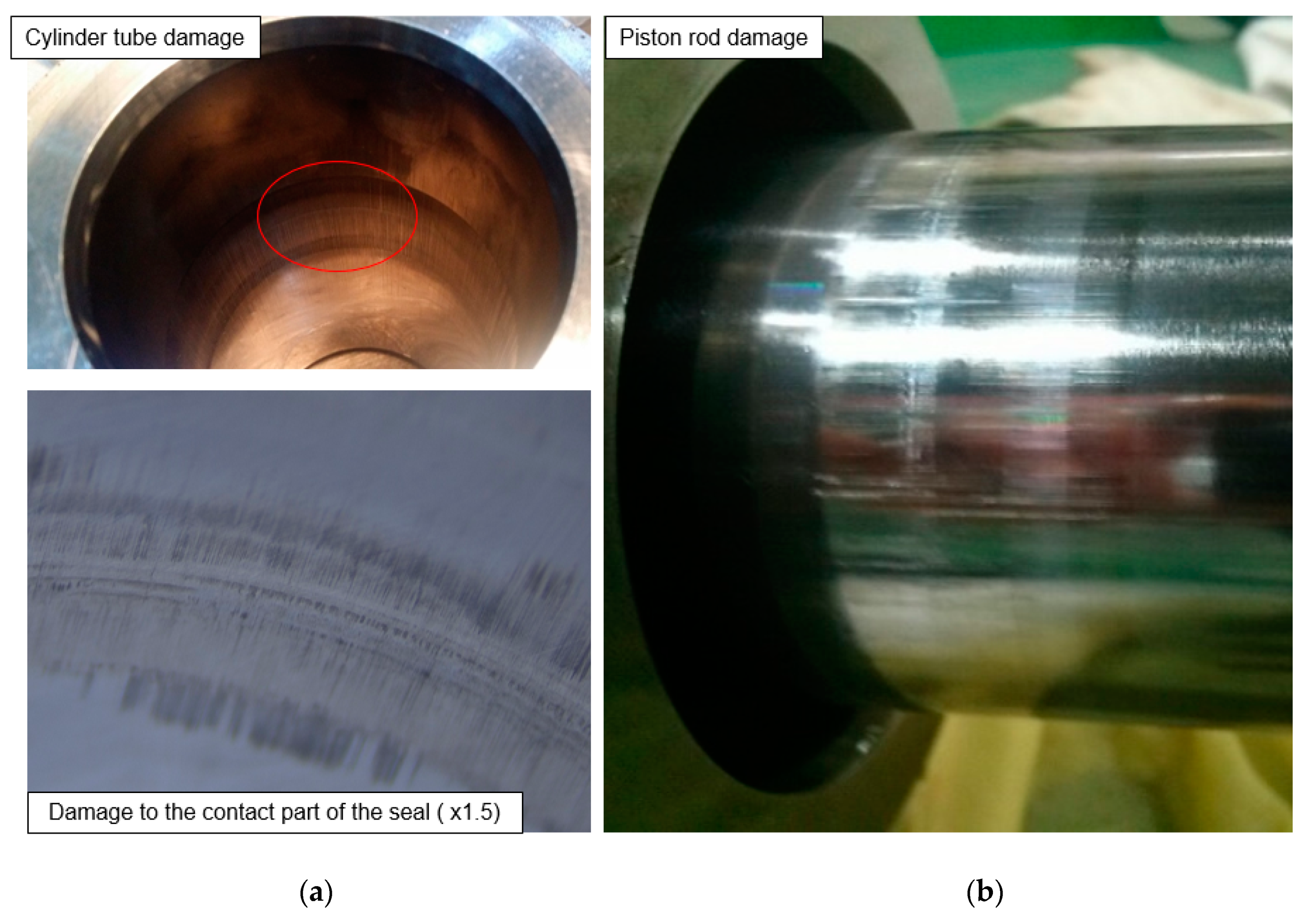
2. Failure Mode Analysis of Hydraulic Servo Actuator

In order to analyze the cause of the failure of the hydraulic servo actuator, the characteristics of use in the test equipment are summarized as follows: first, very fast operating frequency; second, micro displacement; third, high load; fourth, durability; and fifth, increasing the frequency of use.
The results of failure of the hydraulic servo actuators are external leakage and power reduction, reduction in control precision, discoloration of the rod and tube parts, as shown in Figure 3, and noise or overheating. Fast frequency (0.1 to 100 Hz) produces rapid iterative friction on the seal assembly and on the rod and cylinder tube surface. Micro displacement, which is smaller than the width of the seal, inhibits sufficient lubrication and increases friction. In particular, it is not possible to release the residual air and gas inside the hydraulic servo actuator, resulting in high temperature due to the insulation compression of the gas. Additionally, if the operating pressure is increased for the high load test, the pressure of the seal increases and the friction increases.
Hydraulic servo actuators are used in the approximate (0.1–80%) range of maximum stroke.
As the displacement of the actuator fails to operate in the 100% range, the hydraulic oil introduced inside the actuators is not fully drained, the initial pressurization state is maintained continuously, and the hydraulic oil of the micro displacement control level is supplied. At this time, the incoming gas remains inside the actuator, reducing the control precision with compression. The gas in the cylinder and piston chamber is heated by insulation compression, as shown in Equation (1), accelerating the lubrication degradation and resulting in mechanical efficiency degradation and wear failure due to excessive friction.
The oil temperature of the hydraulic system,   T 1 , is managed at 50 °C and the maximum working pressure, P 2 , is used at 21 MPa. Thus, the internal gas rises high to about 500 °C as shown in formula (1), which damages the seal by burning it, which increases friction. Adiabatic coefficient for air k is 1.4 [25,26].
T 2 = T 1 × P 2 · V 2 P 1 · V 1 = T 1 ( P 2 P 1 ) k 1 k = ( 273 + 50 ) × ( 21 1 ) 1.4 1 1.4 771 ( ° K ) 498 ( )
Therefore, the main failure mode was analyzed and found to be the over burning of the seal contact area due to friction, which was analyzed and found to be caused by overloading the seals, incorrect misalignment of the precision device and compression of gas. To solve this problem, low friction hydrostatic bearing should be employed to prevent the overload of the seal part, and misalignment requires the recruitment of bush-use design technology to secure concentricity and the insulation compression of gas requires the use of air-dissipating design technology [27,28].

3. Design of Hydraulic Servo Actuators

In order to solve the problem using hydraulic servo actuators, this study employed a labyrinth seal in the piston section, as shown in Figure 4b, in comparison to the previous use of low friction seals, as shown in Figure 4a.
A hydrostatic bearing was used in the rod section to discharge gas when small amounts of fluid were transferred from high pressure to low pressure in a minute gap. This allowed permanent performance safety and longevity without producing solid friction while operating, even though some loss of flow rate for concentric assurance and lubrication occurred in the design concept.

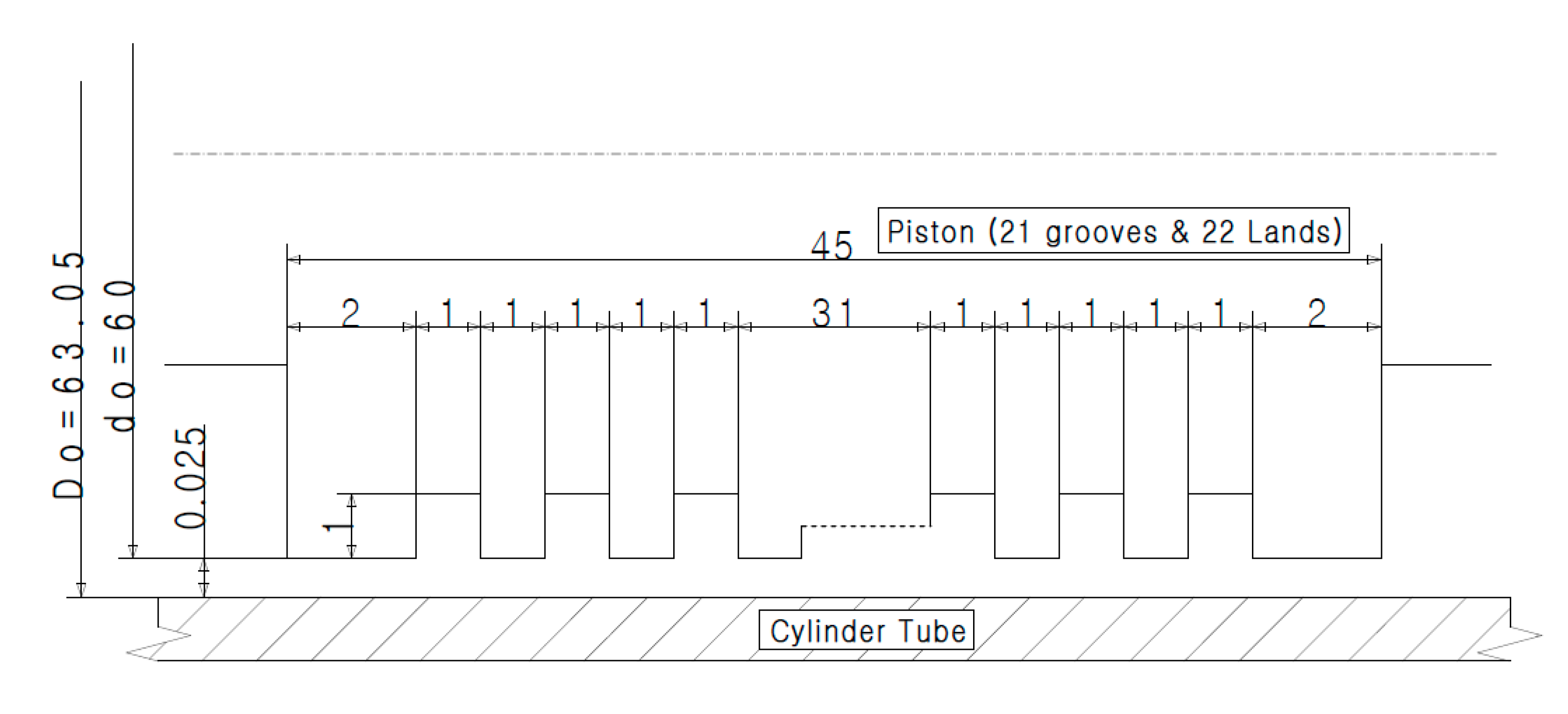
3.1. Low Friction Hydrostatic Bearing

Previously, low fraction elastic seals were used in servo actuators, but friction occurred excessively depending on the characteristics of the seal in direct contact with fast operating frequencies, resulting in a reduced lifetime as well as reduced control precision. Therefore, in this design, four pockets of static pressure bearing were applied for the rod part, as shown in Figure 5, and the labyrinth seal type static pressure bearing for the piston part.
Analysis of the flow characteristics of the static pressure bearing of a typical hydraulic servo actuator shows that the flow from the orifice is the same as Equation (2), and the flow through clearance through the piston rod q 2 and bearing land q 3 part in the bearing pocket is shown in Equation (3).
The flow rate of the land from the static-bearing pocket to the pocket is negligible due to little pressure difference in the neighboring pocket. Where Equations (2)–(4) are combined, the pressure and flow of the pockets can be calculated and the power consumed by the use of static pressure bearing can be identified [29,30].
q 1 = C A 2 g r ( P s P ) × 60
q 2 = δ o 3 P 12 × α 100 × r g × l × π 4 d × 2 × 60
q 3 = 0
here, δ 0 is the radial clearance, P is the internal pressure (MPa), g is the gravity acceleration (m/s2),   r is the oil specific gravity,   l is the clearance length(m), d is the rod diameter(m), and α is the oil viscosity.
In the piston section, the labyrinth seal type static pressure bearing is arranged repeatedly by multiple lands and grooves, and in the modeling tool, the ring gaps of Figure 6 with different diameters are connected repeatedly. The pressure drop P A B passing through the ring gap is then the subtraction of outlet port pressure (port B p ) from input port pressure (port A p ) as shown in Equation (5) and the volume flow Q is the sum of pressure driven flow Q d p (lamina pipe flow or Poiseuille flow) and the velocity driven flow Q d v (drag flow or Couette flow) as shown in Equation (6). In addition, the volume flow rate of the lateral flow condition, disregarding the pressure drop, is the same as Equation (7), and Equation (8) when considering the pressure drop. At this time, K ( R e ) is determined by the Reynolds number and the gap structure [31].
P A B = p o r t A p p o r t B p
Q = Q d p + Q d v
Q = π · d m · s 3 12 · L · v · ρ · ( 1 + 3 2 · e 2 s 2 ) · P A B
Q = π · d m · s 3 12 · L · v · ρ · ( 1 + 3 2 · e 2 s 2 ) · ( 1 1 + K ( R e ) ) · P A B
here,   d m is the middle diameter in the gap(m), s is the mean gap height (m), L is the length (m), v is the kinematic viscosity (m2/s), ρ is the density (kg/m3), R e is the Reynolds number, and e is the factor of eccentricity (m).
In this study, the internal diameter of the cylinder tube was 63.05 mm, in which the diameter of the piston with 22 lands was 63 mm, and the diameter of the piston with 21 grooves arranged 1 mm apart from each land was 61 mm, so the piston and tube gap was designed to be 0.025 mm, as shown in Figure 7.
Using Simulation X 3.7, a dynamic special analysis tool, we modeled the labyrinth seal, as shown in Figure 7, for design optimization and performed the simulated analysis of it with Figure 8.
When the flow passes from the high-pressure (21 MPa) side to the low-pressure side (0 MPa), a vortex flow occurs in each groove, which degrades the pressure, as shown in Figure 9. Assuming that there was no eccentricity, the result of the simulation showed a pressure drop of 5.01% for groove 1 at 19.958 MPa, a pressure drop of 50.59% for groove 10 at 10.375 MPa, and a pressure drop of 92.93% for groove 21 at the end at 1.485 MPa. In addition, it was verified that the flow rate at 21 MPa was 0.27 L/min, that is, 30.34% of the flow rate of 0.89 L/min when the labyrinth seal grooves were not used [32,33,34].
If eccentricity occurs due to the anomaly in static pressure bearing or a large load change of both rods, the result of the simulation in the case of the most eccentric e = ( D 0 d 0 ) / 2 showed a pressure drop of 5.01% at 19.948 MPa, as shown in Figure 10.
The pressure in groove 10 was 10.375 MPa with a pressure drop of 50.59%, and the pressure in the final stage of groove 21 was 1.485 MPa, with a pressure drop of 92.93%. In addition, with the supply pressure of 21 MPa and no eccentricity, the flow rate is analyzed to be 0.27 L/min and with the maximum eccentricity, it is 0.67 L/min. Without the labyrinth seal grooves, the maximum eccentricity was 30.34% and 75.28% of the maximum flow rate of 0.89 L/min.

3.2. Control System Equipped with the Servo Actuator

The design of the hydraulic servo actuator of tensile compression fatigue test equipment has been designed with low friction hydrostatic bearings to solve failure modes. Misalignment was designed with a double bush design for concentricity, and the thermal compression of gas was designed to allow air emissions.
In order to minimize the loss of fluid power in the static pressure bearing, the optimal parameters for the land and groove parts were set through the simulation and the prototype was made according to the specification of the maximum load of 2 ton and maximum displacement of 200 mm.
The proportional integral (PI) controller in a typical Windows operating system (OS) has a limitation of control as the phase difference between the reference signal and feedback signal occurs and increases at frequencies up to 7 Hz. Thus, in order to reduce the phase difference between the reference signal and the feedback signal of the hydraulic servo actuator, a real-time OS-based controller for the operation of the PI controller can be built to implement the computation speed of the reference signal and the feedback signal with at least 100 μs to control up to 100 Hz. The control system of the hydraulic servo actuator is a PI controller based on a real-time OS, which can be controlled in two modes of displacement and force and is configured as shown in Figure 11. As shown in Figure 12, the PI controller is a control technique that uses integral control, which creates control signals by integrating error signals, in parallel to the proportional control.
The transfer function of the PI controller, which is displayed as a transfer function between the error signal and the control signal, is shown in Equation (9). Here, K p is called a proportional factor, and K i is called an integral coefficient.
C ( s ) = U ( s ) E ( s ) = K p + K i s = K p ( s + K i K p ) s

4. Results and Discussion

The tested hydraulic servo actuator was previously designed with a 4-pocket type hydrostatic bearing on both rods to solve the problem of burning contact surfaces due to the friction between the seal and the two loads, and 21 groves and 22 lands were designed with a labyrinth seal that fundamentally blocked the accumulation of gases inside the piston. In addition, a duplex bush design was applied to ensure the concentricity of pistons, cylinder tubes and both rod static pressure bearings.
Therefore, there is no friction because there is no solid contact for fluid sealing unlike before.
As hydraulic oil on the high pressure side is constantly leaking to the low pressure side through a tiny gap (25 μm) in the labyrinth seal, gas flowing in with the hydraulic oil is discharged without accumulating, and no stick slip occurs even in very slow displacement, and there is no gas heating due to compressed heat. This worked particularly reliably when it was controlled at a high frequency—up to 100 Hz.
Figure 13a is a relatively low frequency operating example of a PI controller in Windows OS that tests up to 7 Hz at a stroke of ±20 mm, shows no stick slip, no gas heating due to compression heat, and that operates reliably. Figure 13b indicates that when tested at 7 Hz with the maximum load of ±2 tons of this equipment, no friction loss occurs and it operates reliably with a control force.
Further, no damage or trace was found in the newly improved hydraulic servo actuator and the total test time was reduced by 45% as a result of fatigue testing of a car’s engine mount spring, which was frequently tested at the site, with a peak load of ±1000 kgf and a test frequency of 6 Hz, as shown in Figure 14. To further verify this effect, PI controllers in real-time OS with high-speed frequency control were used to perform normal operations even at very slow frequencies—0.1 Hz. It was also able to accurately control in the range of 100 Hz, which is the high frequency range. Test results using the PI controller of a real-time operating system show that precise control up to a frequency range of (0.1~100 Hz) was possible, as shown in Figure 15.

5. Conclusions

In this study, damage to the tube and rod surface of the hydraulic servo actuator was caused by burning and the generation of high heat, especially with the oil temperature controlled at a level of 50 °C. This was first analyzed to be caused by the temperature of the gas accumulated in the oil chamber of the actuators, which rose to about 500 °C through adiabatic compression, which inhibited the lubrication of the seal and increased friction. For the failed thrust 2 ton motor vehicle component life tester, the piston was replaced by a friction seal of the labyrinth seal type, and the rod was optimized by using a 4-pocket type static pressure bearing, and a dynamic modelling & simulation tool. The newly designed hydraulic servo actuators were able to operate up to 100 Hz at the existing 3.3 Hz level, and since solid friction was not generated, the semi-permanent lifetime was secured.

Author Contributions

Conceptualization, Y.-b.L.; writing—original draft, J.-w.P.; funding acquisition, Y.-b.L., J.-w.P. and G.-c.L.; investigation, Y.-b.L. and J.-w.P.; methodology and evaluation, J.-w.P. and G.-c.L.; writing—review and editing, Y.-b.L., J.-w.P. and G.-c.L. All authors have read and agreed to the published version of the manuscript.

Funding

This work was supported by the Material and Component Fusion Alliance (No. 1415166303) and the Development Project on Virtual Engineering Platform for Future Transportation Parts Manufacturing (No. 1415166310) of the Ministry of Trade, Industry and Energy, Korea.

Conflicts of Interest

The authors declare no conflict of interest.

References

  1. Alleyne, A.; Liu, R. A simplified approach to force control for electro-hydraulic systems. Control Eng. Pr. 2000, 8, 1347–1356. [Google Scholar] [CrossRef]
  2. Bonchis, A.; Corke, P.; Rye, D.; Ha, Q. Variable structure methods in hydraulic servo systems control. Automatica 2001, 37, 589–595. [Google Scholar] [CrossRef]
  3. Pugi, L.; Pagliai, M.; Nocentini, A.; Lutzemberger, G.; Pretto, A. Design of a hydraulic servo-actuation fed by a regenerative braking system. Appl. Energy 2017, 187, 96–115. [Google Scholar] [CrossRef]
  4. Kim, M.Y.; Lee, C.-O. An experimental study on the optimization of controller gains for an electro-hydraulic servo system using evolution strategies. Control Eng. Pr. 2006, 14, 137–147. [Google Scholar] [CrossRef]
  5. Hua, Z.; Rong, X.; Li, Y.; Chai, H.; Li, B.; Zhang, S. Analysis and Verification on Energy Consumption of the Quadruped Robot with Passive Compliant Hydraulic Servo Actuator. Appl. Sci. 2020, 10, 340. [Google Scholar] [CrossRef] [Green Version]
  6. Liu, J.; Qiao, B.-J.; Chen, X.-F.; Yan, R.; Chen, X. Adaptive vibration control on electrohydraulic shaking table system with an expanded frequency range: Theory analysis and experimental study. Mech. Syst. Signal Process. 2019, 132, 122–137. [Google Scholar] [CrossRef]
  7. Guan, C.; Pan, S. Adaptive sliding mode control of electro-hydraulic system with nonlinear unknown parameters. Control Eng. Pr. 2008, 16, 1275–1284. [Google Scholar] [CrossRef]
  8. Montanari, M.; Ronchi, F.; Rossi, C.; Tilli, A. Backstepping Position Control of a Hydraulically Actuated Clutch Servo System. IFAC Proc. Vol. 2004, 37, 139–144. [Google Scholar] [CrossRef]
  9. Montanari, M.; Ronchi, F.; Rossi, C.; Tilli, A.; Tonielli, A. Control and performance evaluation of a clutch servo system with hydraulic actuation. Control Eng. Pr. 2004, 12, 1369–1379. [Google Scholar] [CrossRef]
  10. Yang, G.; Yao, J. High-precision motion servo control of double-rod electro-hydraulic actuators with exact tracking performance. ISA Trans. 2020, 103, 266–279. [Google Scholar] [CrossRef]
  11. Zhang, K.; Yao, J.; Jiang, T. Degradation assessment and life prediction of electro-hydraulic servo valve under erosion wear. Eng. Fail. Anal. 2014, 36, 284–300. [Google Scholar] [CrossRef]
  12. Mochocki, W.; Radoń, U. Analysis of Basic Failure Scenarios of a Truss Tower in a Probabilistic Approach. Appl. Sci. 2019, 9, 2662. [Google Scholar] [CrossRef] [Green Version]
  13. Park, S.; Choi, S.; Sikorsky, C.; Stubbs, N. Efficient method for calculation of system reliability of a complex structure. Int. J. Solids Struct. 2004, 41, 5035–5050. [Google Scholar] [CrossRef]
  14. Sebe, N.; Suyama, K. Fault-Tolerant Servo Systems against Actuator Failures. In Proceedings of the 7th IFAC Symposium on Robust Control Design, The International Federation of Automatic Control, Aalborg, Denmark, 20–22 June 2012; pp. 505–510. [Google Scholar]
  15. Yang, G.; Yao, J. Output feedback control of electro-hydraulic servo actuators with matched and mismatched disturbances rejection. J. Frankl. Inst. 2019, 356, 9152–9179. [Google Scholar] [CrossRef]
  16. Macaluso, A.; Jacazio, G. Prognostic and Health Management System for Fly-by-wire Electro-hydraulic Servo Actuators for Detection and Tracking of Actuator Faults. Procedia CIRP 2017, 59, 116–121. [Google Scholar] [CrossRef]
  17. Márton, L.; Fodor, S.; Sepehri, N. A practical method for friction identification in hydraulic actuators. Mechatronics 2011, 21, 350–356. [Google Scholar] [CrossRef]
  18. Yao, B.; Bu, F.; Chiu, G.T.C. Adaptive Robust Motion Control of Electro-Hydraulic Servo Systems Driven by Single-Rod Actuators; IFAC Motion Control: Grenoble, France, 1998; pp. 49–54. [Google Scholar]
  19. Qian, Y.; Ou, G.; Maghareh, A.; Dyke, S.J. Parametric identification of a servo-hydraulic actuator for real-time hybrid simulation. Mech. Syst. Signal Process. 2014, 48, 260–273. [Google Scholar] [CrossRef]
  20. Maghareh, A.; Silva, C.E.; Dyke, S.J. Parametric model of servo-hydraulic actuator coupled with a nonlinear system: Experimental validation. Mech. Syst. Signal Process. 2018, 104, 663–672. [Google Scholar] [CrossRef]
  21. Maghareh, A.; Silva, C.E.; Dyke, S.J. Servo-hydraulic actuator in controllable canonical form: Identification and experimental validation. Mech. Syst. Signal Process. 2018, 100, 398–414. [Google Scholar] [CrossRef]
  22. Plummer, A.R. Control techniques for structural testing: A review. Syst. Control Eng. 2007, 221, 139–169. [Google Scholar] [CrossRef]
  23. Choi, H.; Han, C.; Hong, W.; Kang, E.; Choi, H. Dual Servo Mechanism for High Precision Positioning with VCM and PZT Actuator. IFAC Proc. Vol. 2004, 37, 283–288. [Google Scholar] [CrossRef]
  24. Fischer, J.; Bradler, P.R.; Lang, R.W. Test equipment for fatigue crack growth testing of polymeric materials in chlorinated water at different temperatures. Eng. Fract. Mech. 2018, 203, 44–53. [Google Scholar] [CrossRef]
  25. Lee, Y.B.; Lee, J.J. A Study on the Air Vent Valve of the Hydraulic Servo Actuator for Steam Control of Power Plants. Trans. Korean Soc. Mech. Eng. B 2016, 40, 397–402. [Google Scholar] [CrossRef]
  26. Lee, Y.B.; Jung, D.S.; Lee, G.C.; Kang, B.S.; Lee, J.J. A Study on the Main Failure Mode Analysis and Lifetime Improvement of Hydraulic Servo Actuators. J. Drive Control 2018, 15, 48–54. [Google Scholar]
  27. Lee, Y.; Yoon, Y.H. Modeling & Simulation of a Hydraulic Servo Actuator Cushion for Power Plants. J. Korean Soc. Tribol. Lubr. Eng. 2013, 29, 7–12. [Google Scholar] [CrossRef]
  28. Lee, Y.B.; Lee, G.C.; Chang, M.S. Study of Wear Characteristics of Hydraulic Equipment Used in Power Plants. Trans. Korean Soc. Mech. Eng. A 2013, 37, 1183–1188. [Google Scholar] [CrossRef] [Green Version]
  29. Goodwin, A.B. Fluid Power Systems-Theory, Worked Example and Problems; The Macmillan Press: London/Basinstoke, UK, 1976. [Google Scholar]
  30. Cameron, A. Basic Lubrication Theory, 3rd ed.; Ellis Horwood Limited: West Sussex, UK, 1981; pp. 168–178. [Google Scholar]
  31. Simulation, X. Training guide, ESI ITI GmbH, Professional Edition Vision 4.1; J&F Solution: Kowloon Bay, China, 2020; pp. 8–421. [Google Scholar]
  32. Lee, Y. A New Approach to the High Efficiency of Hydraulic Excavator. J. Drive Control 2014, 11, 39–45. [Google Scholar] [CrossRef] [Green Version]
  33. Park, T.J. Analysis of flow characteristics in a groove of hydraulic spool valve. J. Korea Fluid Power Syst. Soc. 2007, 4, 15–20. [Google Scholar]
  34. Hong, S.-H.; Son, S.-I.; Kim, K.-W. Study on Lubrication Characteristics of Spool Valve with Various Cross-sectional Groove Shapes. J. Korean Soc. Tribol. Lubr. Eng. 2013, 29, 149–159. [Google Scholar] [CrossRef] [Green Version]
Figure 1. Tensile compression fatigue test equipment.
Applsci 10 07451 g001
Figure 2. Fatigue test equipment equipped with hydraulic servo actuators developed under test.
Applsci 10 07451 g002
Figure 3. Fault picture of hydraulic servo actuator (a) Tube burning (b) Rod burning.
Applsci 10 07451 g003
Figure 4. Comparison of elastic seal type and labyrinth seal type. (a) Low friction seal; (b) Labyrinth seal.
Applsci 10 07451 g004
Figure 5. Flow characteristics of hydrostatic bearing.
Applsci 10 07451 g005
Figure 6. Ring gap for modeling the piston labyrinth seal.
Applsci 10 07451 g006
Figure 7. Dimensional arrangement of the five square grooves.
Applsci 10 07451 g007
Figure 8. Modeling of labyrinth seal for piston.
Applsci 10 07451 g008
Figure 9. Result of labyrinth seal simulation.
Applsci 10 07451 g009
Figure 10. Pressure drop of the fluid flow through 21 radial grooves.
Applsci 10 07451 g010
Figure 11. Real-time system block diagram.
Applsci 10 07451 g011
Figure 12. Block diagram of actuator control system.
Applsci 10 07451 g012
Figure 13. Results of hydraulic servo actuator according to the frequency change of the power control device.
Applsci 10 07451 g013
Figure 14. Fatigue life test of engine mount spring with large eccentric load (106 cycles).
Applsci 10 07451 g014
Figure 15. Displacement test results of hydraulic servo actuator according to the frequency change of the power control device.
Applsci 10 07451 g015
Publisher’s Note: MDPI stays neutral with regard to jurisdictional claims in published maps and institutional affiliations.

