Article

Long-Term Remote Monitoring of Ground Deformation Using Sentinel-1 Interferometric Synthetic Aperture Radar (InSAR): Applications and Insights into Geotechnical Engineering Practices

Department of Civil and Environmental Engineering, Korea Advanced Institute of Science and Technology (KAIST), Daejeon 34141, Korea
*
Author to whom correspondence should be addressed.
Appl. Sci. 2020, 10(21), 7447; https://doi.org/10.3390/app10217447
Submission received: 29 September 2020 / Revised: 17 October 2020 / Accepted: 21 October 2020 / Published: 23 October 2020
(This article belongs to the Special Issue Advances in Geotechnical Engineering)

Abstract

:
Development of synthetic aperture radar (SAR) technology and the dedicated suite of processing tools have aided the evolution of remote sensing techniques for various Earth Observation (EO) applications. Interferometric SAR (InSAR) is a relatively new geodetic technique which provides high-speed and reliable geographic, geologic, and hazards information allowing the prognosis of future environmental and urban planning. In this study, we explored the applicability of two differential interferometry techniques, conventional and advanced differential InSAR (A-DInSAR), for topographic mapping and long-term geotechnical monitoring by exploiting satellite data, particularly Sentinel-1 SAR data, which is publicly shared. We specifically used the open-source tools of SeNtinel Application Platform (SNAP) and Stanford Method for Persistent Scatterers (StaMPS) for interferometric data processing to implement A-DInSAR. This study presents various applications, which include generation of a digital elevation model (DEM), mapping of seismically induced displacement and associated damages, and detection and long-term monitoring of tunneling-induced ground deformation and rainfall-induced landslide. Geometric and temporal decorrelations posed challenges and limitations in the successful implementation of Sentinel-1 SAR interferometry specifically in vegetated areas. The presented results proved the validity and reliability of the exploited SAR data and InSAR techniques for addressing geotechnical engineering related problems.

1. Introduction

High precision geodetic measurements with coarse-to-fine spatial and temporal resolutions significantly complement geological, seismic, and geotechnical investigations and characterizations of geodynamic processes related to natural and human-induced activities. The continual development of synthetic aperture radar (SAR) technology and the dedicated suite of processing tools over the past years have introduced numerous opportunities in the fields of remote sensing and civil engineering. Interferometric SAR (InSAR) and advanced differential InSAR (A-DInSAR) are relatively new geodetic techniques in these fields which have proven their capability of providing centimeter- to millimeter-level change records of terrain topography and surface deformations. SAR pixel-based derived classifications and measurements promote it from the sparse point Global Positioning System (GPS) technology, while processing both SAR amplitude and phase information make it unique and advantageous over conventional imaging techniques.
The DInSAR technique utilizes the phase information contained between two complex SAR images captured in different times over the same region and forms an interferometric pair. However, these acquired images must share almost the same geometry in order to obtain coherent interferometric pairs that are useful for digital elevation model (DEM) generation or deformation detection, mapping, and monitoring. Decorrelations [1,2] related to atmospheric perturbations in different acquisitions, system noise signal, reference DEM, orbit and baseline inaccuracies are common sources of errors in conventional DInSAR. A-DInSAR also known as multitemporal InSAR (MT-InSAR) and time series InSAR (TS-InSAR) has been developed to overcome these problems. Two general approaches exist nowadays. The Permanent Scatterer InSAR (PS-InSAR) is based on a single master-slave configuration [3]. Many algorithms were developed for this purpose using the same principle. The Small BAseline Subset (SBAS) utilizes the small baseline separation between different interferometric pairs allowing multiple master-slave configurations [4]. Nowadays, these A-DInSAR techniques can be combined or merged as in the Stanford Method for Persistent Scatterers (StaMPS) algorithm [5,6]. Recently, a new method called SqueeSAR is aiming to combine both PS and DS (distributed scatterer) [7].
SAR image pairs have been utilized to generate high-resolution DEM [8,9,10] covering large areas with low costs and high precision. The DInSAR technique has also been successfully employed in several studies for large earthquakes [11,12,13,14] and the utilization of the coherence difference in earthquake damage assessment and liquefaction mapping [15,16,17,18]. Particularly, A-DInSAR techniques can determine spatiotemporal deformation patterns related to tunneling-induced ground subsidence [19,20,21,22,23] and landslides [24,25,26,27,28,29,30]. Its ability to measure both vertical and horizontal displacements with sub-millimeter level accuracy has been proven. While above listed applications are based on the SAR phase information, its application for studying vegetation, soil moisture content, or terrain classification are based on the radar’s capability to reflect the dielectric property of the ground target.
In South Korea, the popularity of SAR data and InSAR techniques in both remote sensing and civil engineering fields has made important contributions in understanding the most recent geological hazards and environmental disasters that posed threats both to infrastructure and public safety. Processing of commercial SAR data acquired by TanDEM-X satellite mission has provided the extraction of high-resolution DEM [31,32] and precise topographic change [33]. InSAR also permitted the study of the deformations induced by several geophysical phenomena in the Korean Peninsula, such as the two reported largest earthquakes in 2016 [34] and in 2017 [35] and vertical land motion due to sea level rise [36]. It has also allowed monitoring of volcanos [37], bridge deflection [38], and buildings due to urban subsidence [39]. However, there are no available records found of case studies in the country that investigate specifically the exploitation of the new generation SAR system Sentinel-1 for tunneling-induced ground deformation and rainfall-induced landslides. Korean local authorities and city planners benefit from the results of these additional investigations through disaster mitigation and risk reduction and design effective plans ensuring the safety of buildings, private and public facilities and ultimately, the people.
This paper describes the different types of InSAR techniques and presents the InSAR-derived results for various geotechnical engineering practices. Specifically, this work addresses the capability of processing freely available Sentinel-1 SAR data using the SeNtinel Application Platform (SNAP) and StaMPS free software packages. The InSAR techniques were implemented for DEM generation, and detection, mapping, and monitoring of ground deformation associated with earthquakes, underground tunneling, and rainfall-induced landslide events in the Korean Peninsula. The remainder of the paper describes InSAR analysis techniques, datasets, and tools used together with the description of the test sites (Section 2), presents the interferometry results (Section 3), discusses their main applications with advantages and limitations (Section 4), and concludes with some outlooks (Section 5).

2. Materials and Methods

2.1. Description of Test Sites

We chose several recent geohazard events in South Korea to examine the capability of remote sensing analysis using freely available SAR data processed with open-source software packages. These events include earthquake-induced, and tunneling-induced ground deformations in urban areas, and a rainfall-induced landslide in a densely vegetated slope that stretches along a national highway, as well as the DEM generation. Figure 1 depicts the selected areas of interest (AOI) investigated in South Korea.

2.1.1. Site A: Seogwipo, Jeju Province

For DEM generation, Seogwipo, the second-largest city located in the southern part of Jeju Island, was chosen. This volcanic island houses a volcanic mountain, called Mt. Halla, at the center of the island (Figure 1), which has a height of 1950 m above sea level with an inclination of approximately 3–5° from the peak [40].

2.1.2. Site B: Pohang, North Gyeongsang Province

For the earthquake-induced ground deformation analysis, the city of Pohang was selected. This city stands on the alluvium deposit located in North Gyeongsang Province and serves as a main seaport in the southeast coast of South Korea. An earthquake with the moment magnitude Mw = 5.4 struck the city on 15 November 2017, one of the strongest and most damaging earthquakes in the Korean Peninsula. It was a moderate-sized earthquake with an estimated focal depth of 5 km [35]. It has an oblique strike-slip mechanism with a reverse faulting. Over 1000 aftershocks followed the mainshock, and among them, the largest event was with the magnitude 4.6 on 11 February 2018. Table A1 shows the epicenters of the major seismic events of the Pohang earthquake [41]. Moreover, a local magnitude 3.1 earthquake was relocated during the hydraulic stimulation operations at an Enhanced Geothermal System (EGS) site in Pohang [42]. The mainshock caused widespread liquefaction, and heavily damaged the town of Heunghae and many neighboring villages which in turn resulted in over 80 fatalities and left thousands of people homeless.

2.1.3. Site C: South Chungcheong Province

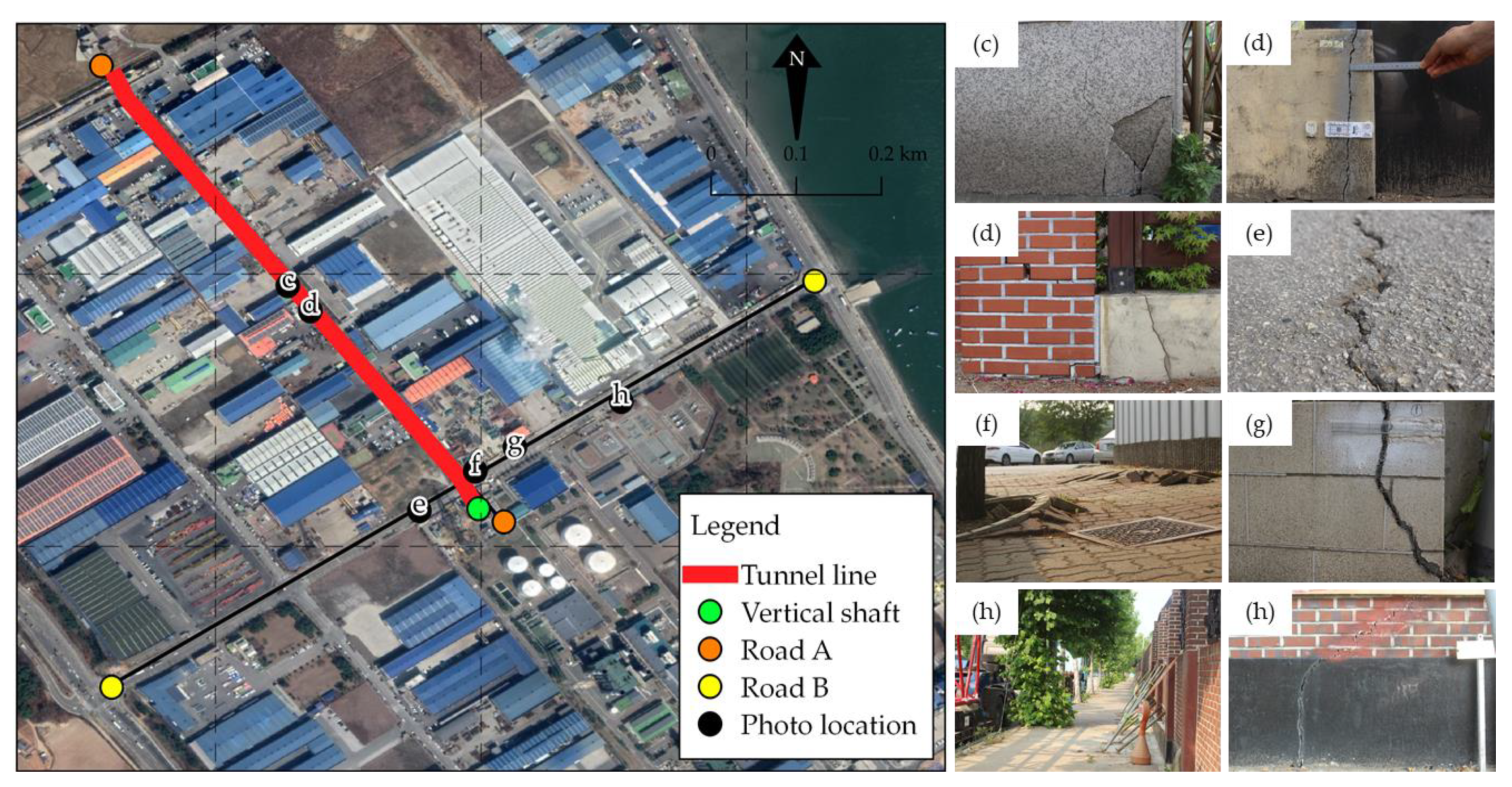
We chose a tunnel construction site in South Chungcheong Province for the tunneling-induced ground deformation analysis. The site has notable geologic characteristics, as follows. (a) This AOI is a reclamation area, which had been subjected to dramatic land development, transforming itself into a coastal industrial zone which houses several manufacturing factories and steel mills. (b) The site is located seaside close to a shore. (c) The geologic strata are composed of a Songak gneiss rock formation and a Pyeongtaek migmatitic gneiss rock formation with overlaying Quaternary alluvial deposits. In the chosen site, excavation of a vertical shaft for the tunnel construction using a shield tunnel boring machine (TBM) began in 2017. The excavation caused excessive inflow of groundwater into the excavated vertical shaft and called pumping-out of the inflowing groundwater with intermittent suspensions of excavation works. After 13 months, the horizontal tunneling of the TBM started. However, when the TBM advanced approximately 95 m after 3 months, it was again temporarily terminated, as damages in neighboring structures and ground cracks along the roads near the vertical shaft were reported, as shown in Figure 2. Table A2 briefly outlines the construction sequence of the tunnel construction schedule.

2.1.4. Site D: Gyeongju, North Gyeongsang Province

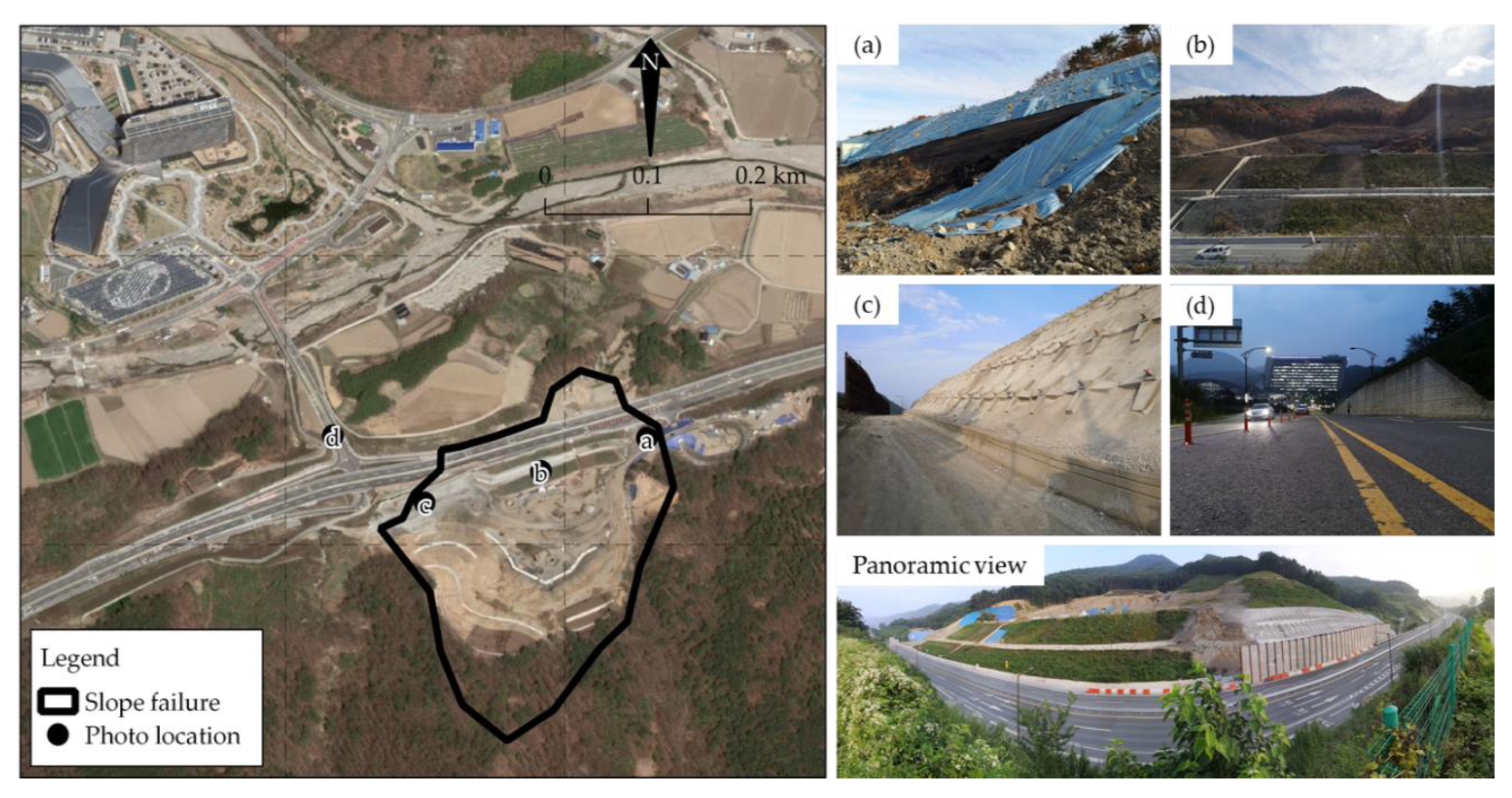
For rainfall-induced landslide analysis, the AOI covers a cut slope along a motorway and its uphill Yangbuk Mountain area in the city of Gyeongju. On 7 October 2018, more than 300 mm of rain fell under the influence of Typhoon Kongrey. This heavy rainfall caused failure of the reinforced slope of 20 m wide and 250 m long, as shown in Figure 3. Slope stabilization works which involved pile reinforcement and groundwater level control were implemented to improve safety. On 30 June 2019, 0.70 km of the Janghang Intersection was opened to relieve the transportation inconvenience. Ramp sections connecting the Janghang Intersection to the building complex were opened on 5 July 2019.

2.2. Datasets Used

This study used Level 1 Single-Look-Complex (SLC) SAR dataset acquired by Sentinel-1 radar system equipped with C-band. This C-band has a radar wavelength of 5.6 cm. The images were acquired using the Interferometric Wide (IW) swath mode with co-vertical polarization (VV). Sentinel-1, a constellation of two satellites, is in a near-polar, sun-synchronous orbit. Therefore, it passes over the AOI in both ascending and descending flights with a 12-day repeat cycle alone. The SAR data are freely shared in public. The Sentinel-1A was launched in 2014 and the Sentinel-1B in 2016 through the COPERNICUS Programme of the European Space Agency (ESA). ESA’s Sentinel-1 missions operate in Terrain Observation by Progressive Scans SAR (TOPSAR) mode which provides a SAR image with wide area coverage of around 250 × 200 km. The IW swath mode captures three swaths comprising a series of bursts. The SAR image has the moderate ground resolution of approximately 14 × 4 m in azimuth (parallel to the flight direction) and range (perpendicular to the flight direction) directions, respectively. Orbit state vectors in the metadata of the acquired SAR products are updated using the Sentinel-1 Precise Orbit Ephemerides (POE) in order to provide refined satellite position and velocity information. Aside from SLC dataset, Ground Range Detected (GRD) and Ocean (OCN) data can also be searched and ordered from the COPERNICUS Sentinel Open Access Hub or Alaska SAR Facility. Table A3 lists the characteristics of Sentinel-1 missions.
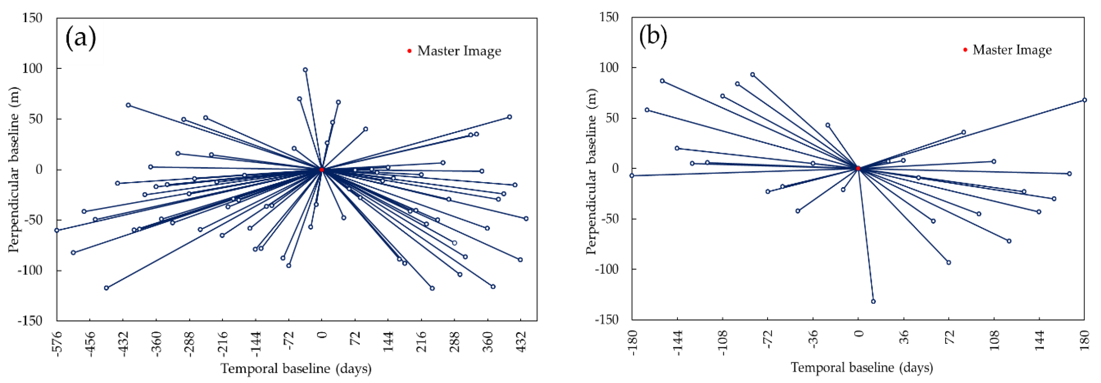
A total of 114 Sentinel-1 SAR scenes were processed: two images for Seogwipo (Site A, descending track 134), three images for Pohang (Site B, descending track 61), 78 images for South Chungcheong province (Site C, descending track 134), and 31 images for Gyeongju (Site D, descending track 61). All images were acquired at night to ensure high signal-to-noise ratio (SNR) and high coherence on the AOIs and mitigate atmospheric delay in the interferometric phase [43,44,45]. Figure 4 shows the Sentinel-1 images connection graph for the A-DInSAR analysis performed in Site C and Site D.
Table 1 lists the summary of applications of interferometry in various geotechnical engineering related problems investigated in South Korea.

2.3. Sentinel-1 SAR Interferometry

2.3.1. Basic Concept

SAR is an active imaging system where the sensor emits microwave radiation to illuminate the Earth’s surface and receives the reflected signal, called backscatterer. It works any time of the day and in any cloud-cover condition towards the surface. The backscattered signals are expressed as an image of which each pixel contains both amplitude (A) and phase (φ) information, recorded as complex numbers (c) [46]:
c = A e i φ
where i is the imaginary number. By pairing two SAR images obtained at distant periods with disparate look angles over the same location, one image is set as master (m) and the other as slave (s), an interferogram (I) is generated. An interferogram is computed by multiplying the amplitude of both images and calculating the difference in phase (Equation (2)). The InSAR technique exploits the phase difference between φm and φs, named interferometric phase (φip), expressed in Equation (3).
I = c m c s = A m A s e i ( φ m   φ s )
φ m   φ s = φ i p = φ e l e v + φ d e f o + φ f l a t + φ a t m + φ n o i s e
where φelev is the topographic phase, φdefo is the phase contribution due to surface deformation, φflat is the flat-earth phase, φatm is the atmospheric phase screening, and φnoise is the phase noise related to some processing-induced factors. Through interferometry, the desired phase contributor, which is typically the elevation or the surface deformation, can be isolated from the other phase components. However, the final quantitative measurements of elevation or surface deformation from interferometry will greatly depend of the quality of the generated interferogram.
While the SAR technology creates satellite images that cover almost the entire planet, not every resolution cell contains valuable information. The main condition for the InSAR application is the degree of coherence. When ground targets or objects change between acquisition periods, the coherent sum of backscattered signals varies resulting from coherence degradation due to decorrelation. To quantify the impact of decorrelation for our InSAR application, the coherence (γ) is calculated:
γ = | Σ n = 1 N c m c s e i ( φ m   φ s ) | Σ n = 1 N | c m | 2 Σ n = 1 N | c s | 2
where N is the coherence window size. The calculated coherence indicates how identical each pixel is between master and slave scenes from a scale of 0 (completely out of phase) to 1 (completely in phase). Any ground deformation associated with natural hazard generates different radar signal paths for the same ground target between two observation periods. Hence, radar signals received by the sensor from damaged structures such as buildings and road pavements can lead to coherence loss. In principle, under ideal condition co-event image pair coherence (γco) would be lower than that of the pre-event image pair coherence (γpre). The coherence difference (γdiff) between those two pairs can be used to delineate damaged areas after the disastrous event. In this study, the coherence difference is calculated as follows [17,18]:
γ d i f f = γ p r e   γ co

2.3.2. Standard Repeat-Pass Interferometry (Single Pair)

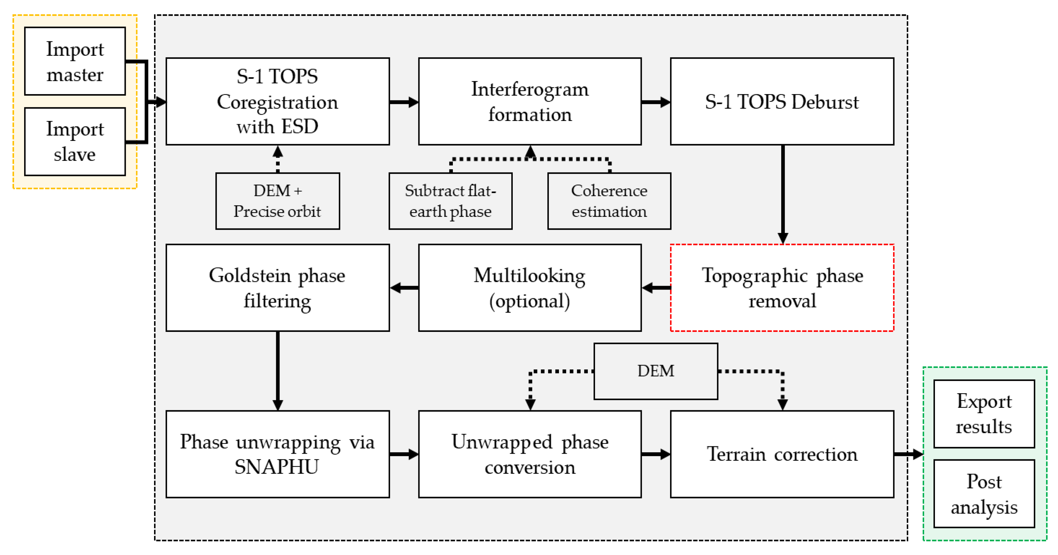
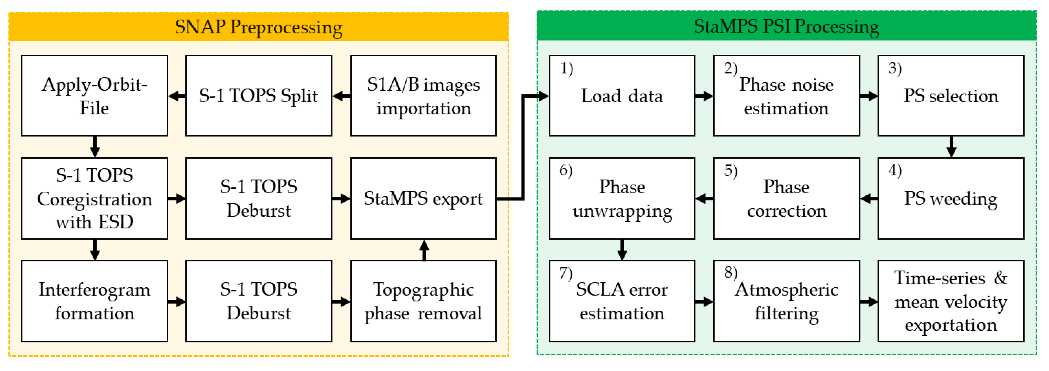
For the DEM generation in Site A (Seogwipo) and earthquake-induced ground deformation in Site B (Pohang), a standard repeat-pass interferometry was conducted by using SNAP (Sentinel-1 Toolbox) developed and freely distributed by ESA. Figure 5 presents the processing chain for the single pair standard repeat-pass InSAR.
First, coregistration of two SAR images employing the Enhanced Spectral Diversity (ESD) method was performed after accurate orbit data implementation to create the interferogram of AOI and after subtraction of flat-earth phase. During the interferogram formation, coherence was also estimated. The output is then debursted to smoothly stitch all burst data into a single image. For the DEM generation, topographic phase was not removed as it is the contributor of interest to be estimated. Moreover, multilooking was not performed as it reduces the spatial resolution of the resulting DEM product. For ground deformation estimation, the topographic phase was removed using precise orbit data and Shuttle Radar Topography Mission (SRTM) DEM 1 arcsec data. Phase filtering was then performed to increase the SNR. Phase unwrapping was performed using the SNAPHU program. Thereafter, the unwrapped phase was converted into either elevation or displacement. The converted product which was still in the radar geometry was then geocoded into the World Geodetic System 1984 (WGS84) and exported for post analysis and visualization in Google Earth and QGIS.

2.3.3. A-DInSAR Analysis with SNAP and StaMPS Integration

The A-DInSAR analysis based on the PS-InSAR technique was performed using the acquired Sentinel-1 free dataset. The PS-InSAR technique has emerged as a matured geodetic monitoring tool characterized by millimeter accuracy. The processing is split into two independent workflows [47,48,49] and presented in Figure 6: (1) single master DInSAR processing through SNAP, and (2) the PS-InSAR processing through StaMPS.
In SNAP processing, the master image was selected using the InSAR Stack Overview tool. The selected master image was approximately in the barycenter of the dataset considering both the temporal and spatial baselines to ensure high coherence in all interferometric pairs generated over the whole stack. Image splitting and orbit file correction were applied, and slave images were coregistered to the geometry of the master image. Interferograms were generated and topographic phase was removed using SRTM DEM 1 arcsec data. Then, debursting was applied to both the original coregistered images and interferograms. Finally, the processed data was exported in a format that is compatible with StaMPS readers. The snap2stamps scripts were used to automate the process except for the master image selection [50]. It is worth noting that interferograms need to be checked before proceeding to the next part to avoid processing errors during the PS-InSAR analysis.
The second part is StaMPS processing. The first step is the preparation of the SNAP exports into StaMPS using the mt_prep_snap script included in the distribution. After running the script, Matlab was launched, and StaMPS processing was subsequently carried out from Step 1 (Load data) through Step 8 (Atmospheric filtering). Additionally, to mitigate the tropospheric phase screens, the aps_linear approach was used as part of the integrated Toolbox for Reducing Atmospheric InSAR Noise (TRAIN) [43]. Finally, the displacement time series and mean annual velocity were exported for post analysis and visualization in StaMPS-Visualizer [51] and QGIS.

3. Results

3.1. DEM Generation over Site A—Seogwipo City

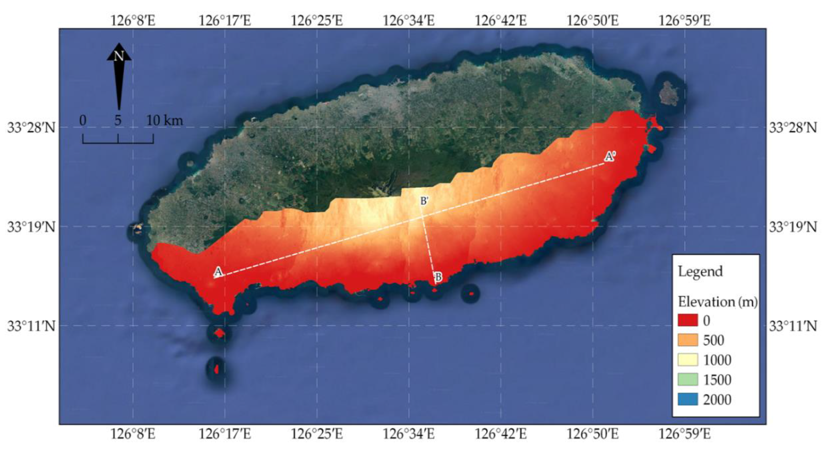
An interferometric pair with the shortest temporal baseline and the highest perpendicular baseline assessed the DEM based on Sentinel-1 SAR data over Seogwipo. Figure 7 shows the interferometric phase generated and the corresponding coherence to check the quality of phase information. The interferometric fringes are clearly shown in the lowlands towards the coast, which is a good indication of topographic information, but are not visible in the vicinity of Mt. Halla. The dominant grassy and vegetated nature of the AOI in the vicinity of Mt. Halla caused considerable loss of coherence due to strong temporal decorrelation (i.e., surface change between the 12-day time interval). The mean coherence of the whole AOI is below 0.30. Figure 8 shows the InSAR-derived DEM.
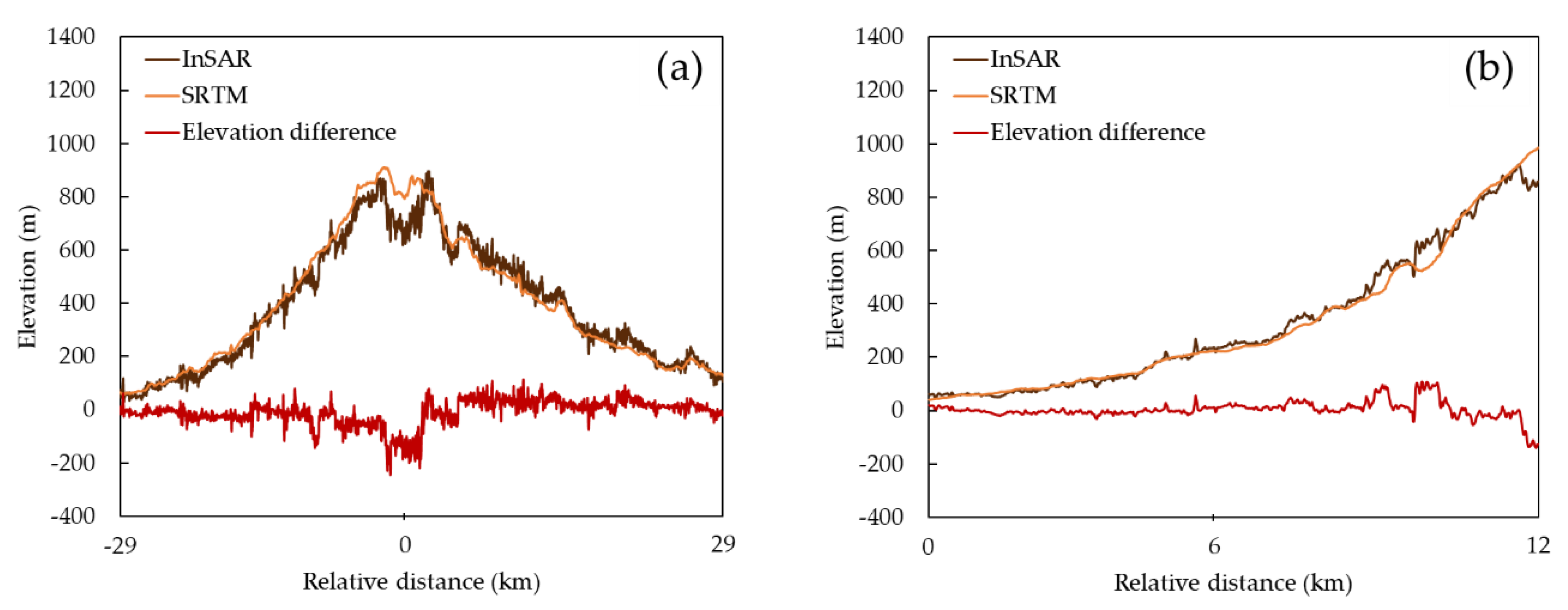
Figure 9 shows the comparison to the reference model (SRTM DEM). Figure 10 shows the elevation profiles along sections A-A’ and B-B’. Although the InSAR-derived DEM and the SRTM DEM appear to be almost similar to each other, the elevation profiles derived from InSAR show more fluctuation compared to the smooth SRTM elevation profiles. More importantly, the InSAR result shows that better elevation measurements can be obtained from plain areas compared to hilly areas and vegetated areas. It underestimates the elevation value towards the mountain peak; the absolute elevation difference can be as high as 250 m. For the lowlands, the absolute elevation difference between InSAR-DEM and SRTM DEM can be as low as 1 m.

3.2. Earthquake-Induced Ground Deformation Mapping over Site B—Pohang City

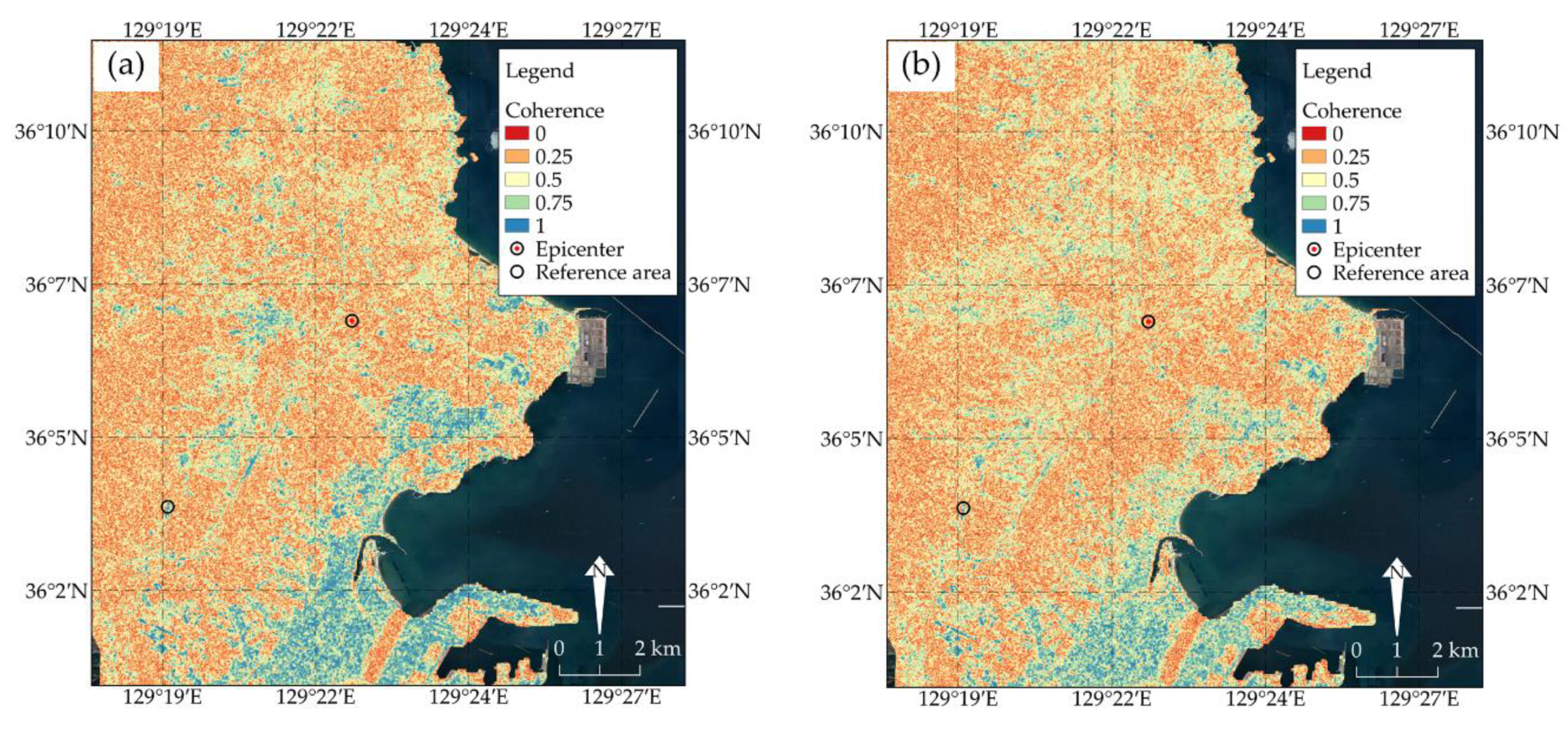
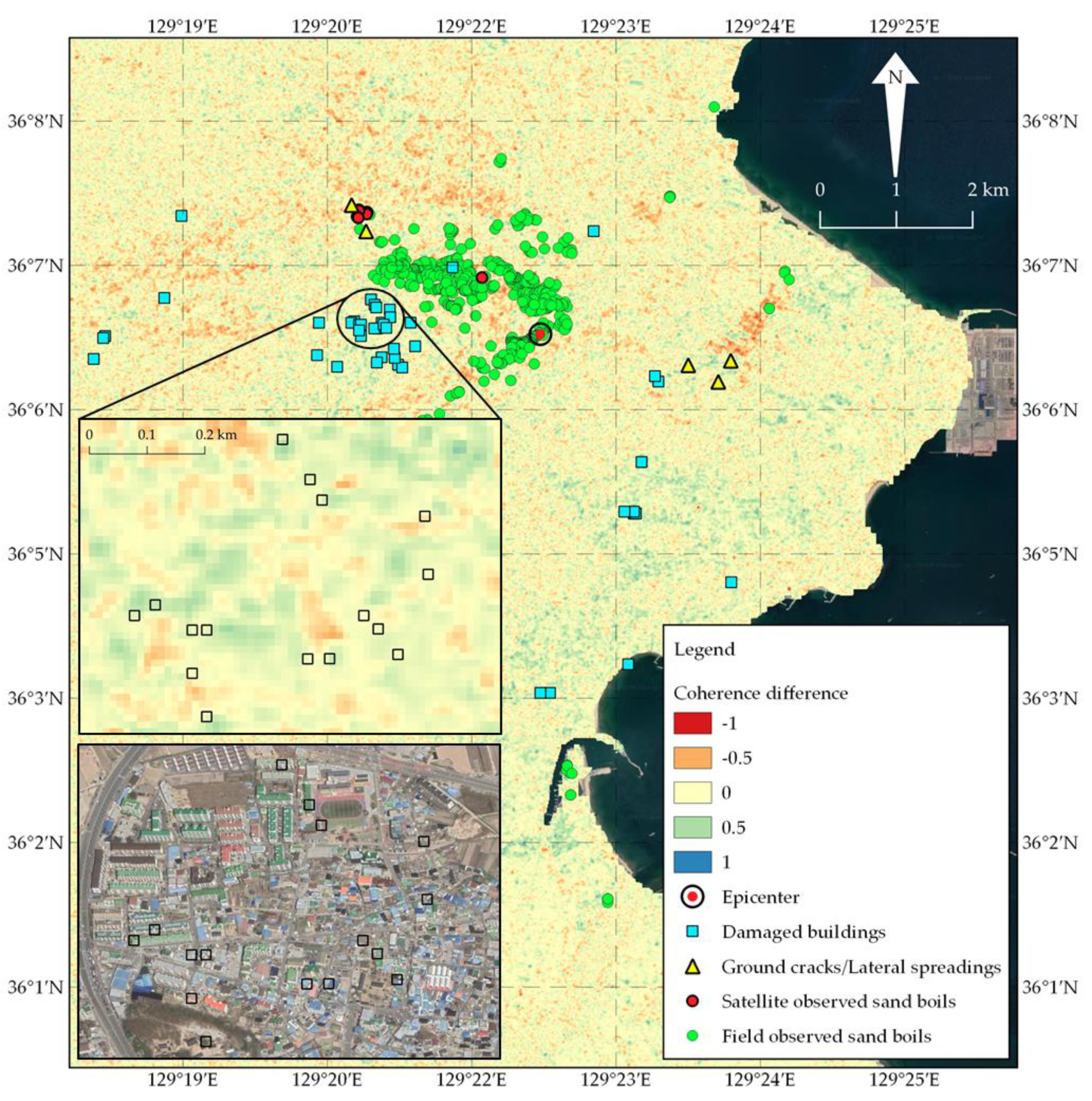
Pre- and co-seismic interferometric pairs were processed to detect the surface changes related to the 15 November 2017 earthquake. Figure 11 presents the pre- and co-seismic coherence maps. It is observed that the overall co-seismic coherence is less than the pre-seismic coherence in most urban areas located in the west, southeast, and southern regions of the epicenter. This coherence degradation indicates the damaged buildings and the inherent differential settlement caused by seismic ground motion and associated liquefaction. Meanwhile, liquefaction phenomena have been reported in the northern and western parts of the epicenter, which is consistent with the observed coherence reduction.
Figure 12 displays the coherence difference map overlaid with the reported liquefaction features, building damages, and ground cracks [41,52,53]. The scale of coherence difference is between −1 and 1. The negative coherence difference (warm color) shows areas that were modified (i.e., by natural processes) before the event but were not modified during the co-seismic interval. The positive coherence difference (cold color) represents areas that had surface changes during the co-seismic interval but little to no change before the event. In the map, positive coherence difference is found mostly in the southeastern part of the AOI, which is associated with damaged buildings in urban areas. Whereas, negative coherence difference is placed dominantly in the northern region. Most areas in this northern part from the epicenter are arable land where little to no liquefaction features were reported [54].
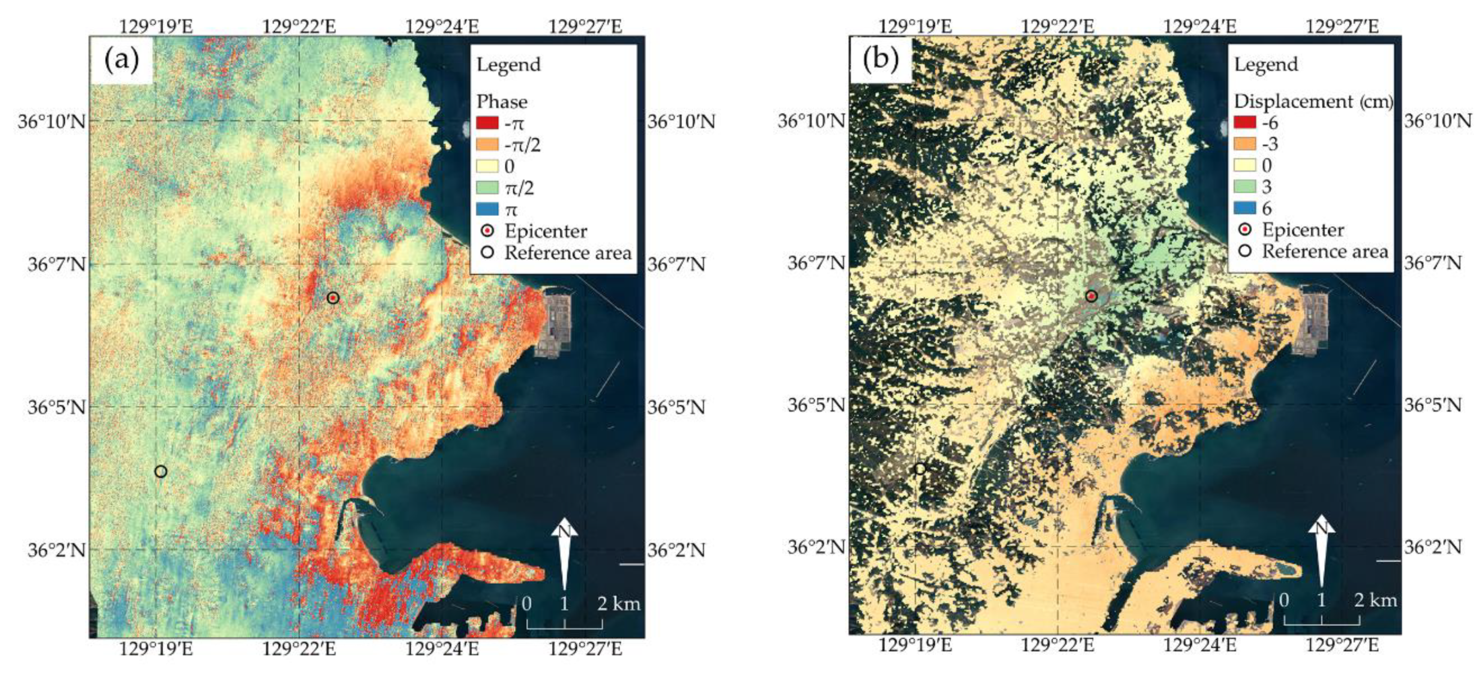
Figure 13 shows the co-seismic differential interferogram and the corresponding ground deformation, which were obtained by using the descending track SAR data. The interferometric fringe delineates the surface displacement in the direction of the radar’s line-of-sight (LOS) in a unit of the radar half-wavelength (i.e., one fringe cycle equals 2.8 cm for Sentinel-1). The interferogram clearly reveals visible co-seismic deformation along the radar LOS. In the displacement map, uplift and subsidence areas were distinguished which caused damage to neighboring buildings. Since Sentinel-1B acquires images in a right-looking mode, positive values indicate uplift and easting, and the negative values suggest subsidence and westing. The reference area, which was assumed not to be affected by the seismic ground motion, is marked on the map and has a coherence value close to 1. The areas (or pixels) with the coherence value less than 0.30 were masked out from the map. Displacement values of more than 5 cm (uplift) from the vicinity of the epicenter were reported.

3.3. Tunneling-Induced Ground Deformation Detection and Monitoring over Site C—Chungcheong

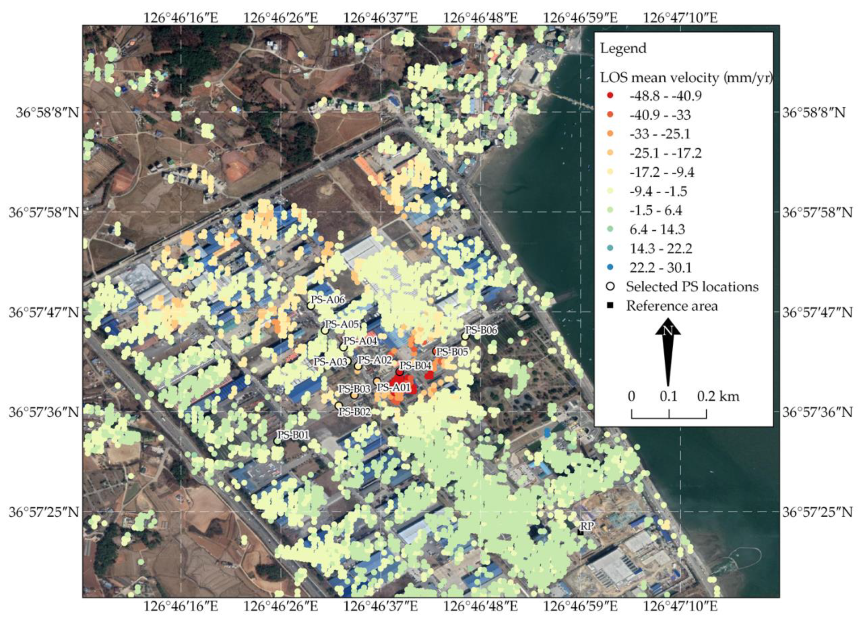
Figure 14 shows the LOS mean velocity for a period of 1009 days estimated by using the PS-InSAR technique from Sentinel-1B data. In the map, the color scale is between −50 and +30 mm/yr. Positive (in blue color) and negative (in red color) values denote movement towards and away from the radar LOS, respectively. Spatial distribution of the PS points was relatively dispersed, showing the complete absence of a rebound deformation trough. Due to the presence of buildings in the project site, the map shows a dense distribution of PS points except in the NW and SW corner regions, where the regions are mostly cultivation lands. A remarkable subsidence trough was observed in the industrial zone where the tunnel construction has commenced and was almost nonexistent in the SE corner region. The subsidence trough consists of yellow, orange, and red color variants depending on the magnitude of deformation.
Figure 15 shows the time histories of InSAR-derived displacements of the selected PS points located along the two road segments (A and B) passing through the vertical shaft. All displacements are estimated in the LOS direction. The tunnel construction phases are highlighted with grey color and marked with letters A–E (Table A2). It is observed that ground deformations near the vertical shaft accelerated during Phase C. Prior to this, no appreciable displacements were recorded along the two roads. Moreover, subsidence increased as the PS distance from the shaft decreased. The settlement started to slow down gradually at the end of Phase D after the shield tunneling was temporarily stopped. No extreme ground deformation was then observed at the end of Phase D that continued towards the end of Phase E. PS-A01, B04, and B05 show the cumulative displacements of more than 5 cm towards the end of the monitoring period.

3.4. Rainfall-Induced Landslide Detection over Site D—Gyeongju

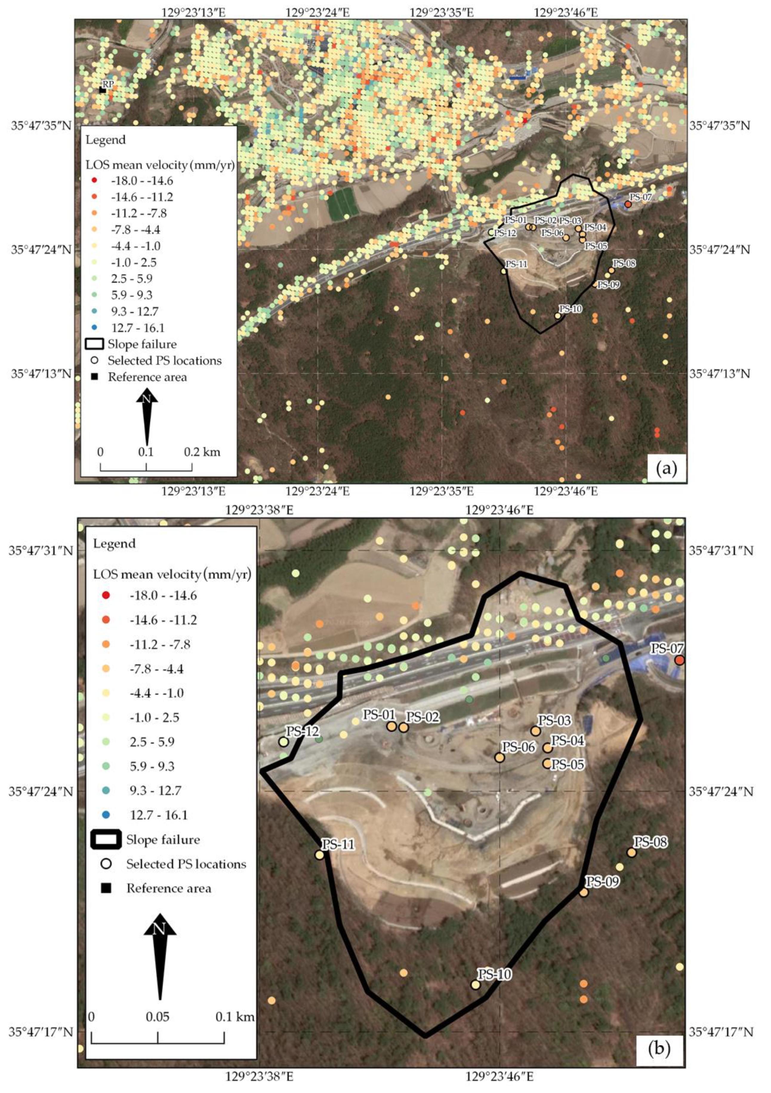
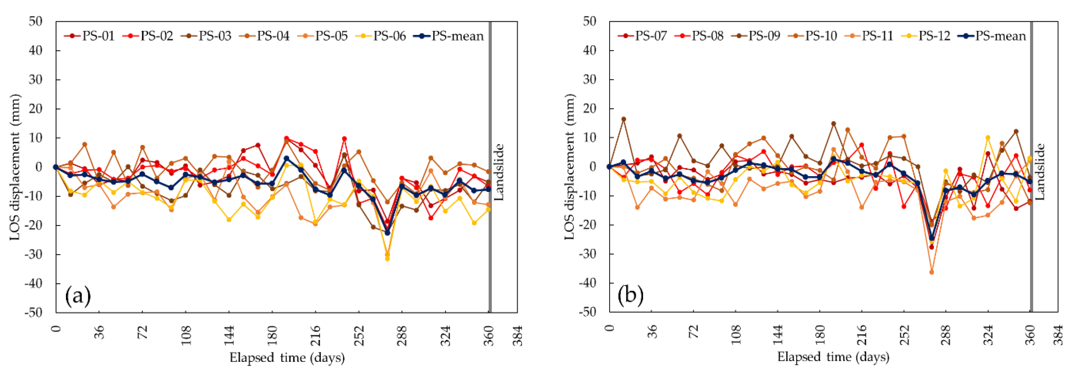
Figure 16 shows the LOS mean velocity for a period of 361 days prior to the landslide as well as the selected PS points over the target AOI. In the map, the color scale is between −18 and +16 mm/yr. The PS points were densely placed in a building complex located on the upper part of the figure and along the National Route 4 of the Janghang Intersection. These PS points showed various motions related to natural factors and seasonal changes (i.e., contraction and expansion due to temperature change).
On the other hand, limited measurement points were present within Yangbuk Mountain due to low coherence related to significant environmental changes between the image acquisitions. The available revisit period was longer than 6 days for the target AOI. Dense vegetation over Yangbuk Mountain led to temporal decorrelation which resulted in bad interferogram quality.
Figure 17 shows the temporal changes in displacement of the selected PS points located within the failed slope and its periphery (Figure 16b). There existed instability patterns throughout the analysis period. The initial plunge in the displacement history plot, which occurred between day 252 and day 288, represents a considerable surface displacement. This time interval in Gyeongju, measured with respect to the first SAR image, has the greatest number of rainfall events that last for about 13 days and typically aggregates to almost 200 mm of precipitation. This also coexists with the occurrence of the monsoon season in the region and with the continuous rain events which starts in late June until early August, displacements are triggered. The mean displacement time series plots of the two groups of measurement points are also shown (Figure 17).

4. Discussion and Outlook

4.1. Advantages and Limitations of InSAR

In this study, our results obtained by using standard repeat-pass InSAR and A-DInSAR (based on PS-InSAR) techniques with Sentinel-1 SAR data and open-source SNAP and StaMPS software packages show its capability in generating DEM and estimating changes in deformation or damages in various geotechnical engineering practices. SAR, as an active radar imaging technique, operates day and night in all weather conditions which has greater advantage over optical remote sensing techniques. InSAR and A-DInSAR techniques have matured and become viable solutions complimenting conventional geodetic, optical, and LiDAR techniques and integrated in multidisciplinary fields. Moreover, the improved temporal and spatial resolutions, wider area coverage, and free access of Sentinel missions allow a weekly repeat observation for ground anomaly detection, and near real-time monitoring of various geohazards.
Meanwhile, the following limiting factors should be accounted for prior to practice. Geometric and temporal decorrelations are the major limiting factors in the successful implementation of Sentinel-1 SAR interferometry [55]. Geometric decorrelation occurs when the geometries of the master and slave images poorly match each other in association with the changes in a look angle and non-parallel orbits. This also happens when the baseline between the two SAR acquisitions deviates, as a result of the satellite’s orbit separation in space, from zero [56]. Non-zero baseline tends to have higher geometric decorrelation. Temporal decorrelation on the other hand occurs as the time separation between SAR observation is large owing to the dynamic surface changes of the Earth. Shorter temporal baseline ensures that these changes can be captured related to the SAR phase, hence, minimizing the temporal decorrelation.
For deformation detection, mapping, and monitoring at the rest of the test sites (Sites B, C, and D), a shorter perpendicular baseline is favored to reduce the phase signal due to topography. Meanwhile, the temporal baseline depends on the magnitude and type of deformation being investigated. Thanks to the short revisit times and tight orbital navigation of Sentinel-1 constellation (Figure 4 and Table 1), these decorrelation effects were minimized. In addition to these decorrelations, atmospheric perturbations also affect the propagation of the SAR signals on standard repeat-pass InSAR that was used for the Pohang earthquake at Site B.
The proportion of Sentinel-1′s short wavelength to the size of water molecules as it comes closer to the edge of the atmospheric window makes it sensitive to atmospheric effects. The troposphere and ionosphere tend to delay and accelerate, respectively, the electromagnetic wave, which yields incorrect elevation and deformation calculations. Geometric distortions due to layover, foreshortening, and shadowing in mountainous regions could result in miscalculations especially for landslide applications (i.e., in Gyeongju) [29]. Layover occurs when the top of the mountain appears before its bottom in the radar LOS. Foreshortening exists when the slope angle is less than the incidence angle of the observation. Whereas, shadowing happens when the mountain blocks the view of observation.

4.2. Possible Improvement of InSAR-Based Detection and Monitoring

The C-band Sentinel-1 mission currently provides free, open-access, medium-resolution SAR image data with worldwide coverage, which we used in this study for various geotechnical engineering related phenomena. The datasets were processed using SNAP and StaMPS which are also open-source software packages. The potential of using shared data and tools can be further utilized for recurring geohazards caused by natural phenomena and human activities around the world. This is possible by (1) combining both Sentinel-1A/B SAR data to achieve an effective 6-day revisiting period which is shorter compared to the 12-day repeat cycle for one constellation alone (if available), (2) combining both ascending and descending data from the same orbit to obtain the true N–S and E–W ground motions, (3) acquiring short-time span and high-resolution SAR products (i.e., from COSMO-SkyMed and TerraSAR-X), and (4) using SAR data acquired with longer radar wavelength (i.e., from ALOS PALSAR 2). Furthermore, (5) no means least is the integration of InSAR techniques with other surveying methods. Use of precise leveling for monitoring of ground movements can complement the satellite-based remote sensing techniques after InSAR detects a potential threat due to ground deformations caused by natural factors and human activities. These further improvements ensure more efficient temporal decorrelation consideration and more PS detection capability even in sub-urban and/or rural areas. As one of the possible examples, these enhancements will allow to inspect and manage the tunnel construction sequence before proceeding to the next stage when untoward incidents happen. Infrastructures and people’s lives can also be safeguarded against landslides if an early detection method of precursory slope movement is in place.

5. Conclusions

This work highlighted the limitations, performance, and the great contribution of using medium-resolution SAR images for various geotechnical engineering related phenomena. The study demonstrated the applicability of using shared Sentinel-1 SAR data provided by ESA under the COPERNICUS Programme processed with open-source software packages, SNAP and StaMPS, employing the conventional and advanced interferometric processing. Two well-defined processing workflows were presented and tested in four geotechnical engineering applications namely DEM generation, earthquake- and tunneling-induced ground deformations, and rainfall-induced landslide in the Korean Peninsula. The major limitations of SAR interferometry were also discussed, which will serve as important pointers in future projects involving continuous deformation monitoring and landslide early detection with improved satellites features.
Overall, the challenges that the authors have encountered on using open data and open-source software tools have created and promoted a conducive and scientific learning environment between remote sensing and geotechnical engineering fields. The experience gained through this work opens new opportunities to explore in addressing timely social and environmental impacts of various geohazards.

Author Contributions

Study design, R.R. and T.-H.K.; methodology, R.R.; formal analysis, R.R. and T.-H.K.; data curation, R.R.; writing—Original draft preparation, R.R.; writing—Review and editing, R.R., T.-H.K. and S.-R.L.; project administration, S.-R.L.; funding acquisition, S.-R.L. All authors have read and agreed to the published version of the manuscript.

Funding

This research was supported by the Basic Research Laboratory Program through the National Research Foundation of Korea (NRF) funded by the MSIT (NRF-2018R1A4A1025765).

Acknowledgments

The authors would like to thank the European Space Agency (ESA) for freely supplying Sentinel-1 SAR data under the COPERNICUS Programme (https://scihub.copernicus.eu). The authors would also like to thank the United States Geological Survey (USGS) in cooperation with the National Aeronautics and Space Administration (NASA) for providing the SRTM DEM (https://earthexplorer.usgs.gov). SNAP (by ESA), StaMPS (by Andrew Hooper), and TRAIN (by David Bekaert) software packages are freely distributed under GNU-GPL license.

Conflicts of Interest

The authors declare no conflict of interest.

Appendix A

Table A1. Summary of major earthquake events in Pohang (Site A) [41].
EarthquakeDate and Time of Occurrence (KST)EpicenterDepth (km)ML
LatitudeLongitude
Mainshock2017.11.15 14:29:3136.11129.377.05.4
Aftershock 12017.11.15 16:49:3036.12129.3610.04.3
Aftershock 22017.11.16 09:02:4236.12129.378.03.6
Aftershock 32017.11.19 23:45:4736.12129.369.03.5
Aftershock 42017.11.20 06:05:1536.14129.3612.03.6
Aftershock 52017.12.25 16:19:2236.11129.3610.03.5
Aftershock 62018.02.11 05:03:3336.08129.339.04.6
Table A2. Construction phases of the shield tunneling in South Chungcheong Province (Site C).
StructurePhaseElapsed Time, DaysActivity
Vertical shaftA385Start excavation
454Stop drilling due to groundwater inflow
B454Restoration of groundwater level
597Restoration of groundwater level completion
C598Restart excavation
751Excavation completion
E947Start of slip foam construction work
989Slip foam construction work completion
1008Restoration of groundwater level
Shield tunnelD788Start TBM drilling
875Stop construction
Table A3. ESA’s Sentinel-1 mission specifications.
ParameterDefinition
Launch date3 April 2014 (Sentinel-1A), 22 April 2016 (Sentinel-1B)
Type of orbitNear-polar Sun-synchronous
Altitude693 km
Band, frequency, wavelengthC-band, 4–8 GHz, 5.55 cm
Repeat cycle12 days (6 days with Sentinel-1A/B ensembled orbits)
PolarizationSingle (HH or VV) or Dual (HH + HV or VV + VH)
Look directionRight side-looking
Type of productsLevel 0 (Raw data), Level 1 (Single Look Complex, Ground Range Detected), Level 2 (Ocean)
Acquisition modesStripmap Mode (SM), Interferometric Wide Swath Mode (IW), Extra Wide Swath Mode (EW), Wave Mode (WM)
IW SLC features
Nominal resolution20 × 5 m (azimuth × range)
Ground swath width250 km
Incidence angle32.9° (IW1), 38.3° (IW2), 43.1° (IW3)

References

  1. Zebker, H.A. Decorrelation in interferometric radar echoes. IEEE Trans. Geosci. Remote Sens. 1992, 30, 950–959. [Google Scholar] [CrossRef] [Green Version]
  2. Gatelli, F.; Monti Guarnieri, A.; Parizzi, F.; Pasquali, P.; Prati, C.; Rocca, F. The wavenumber shift in SAR interferometry. IEEE Trans. Geosci. Remote Sens. 1994, 32, 855–865. [Google Scholar] [CrossRef] [Green Version]
  3. Ferretti, A.; Prati, C.; Rocca, F. Permanent scatterers in SAR interferometry. IEEE Trans. Geosci. Remote Sens. 2001, 39, 8–20. [Google Scholar] [CrossRef]
  4. Berardino, P.; Fornaro, G.; Lanari, R.; Sansosti, E. A new algorithm for surface deformation monitoring based on small baseline differential SAR interferograms. IEEE Trans. Geosci. Remote Sens. 2002, 40, 2375–2383. [Google Scholar] [CrossRef] [Green Version]
  5. Hooper, A. A multi-temporal InSAR method incorporating both persistent scatterer and small baseline approaches. Geophys. Res. Lett. 2008, 35, L16302. [Google Scholar] [CrossRef] [Green Version]
  6. Hooper, A.; Bekaert, D.; Spaans, K.; Arikan, M. Recent advances in SAR interferometry time series analysis for measuring crustal deformation. Tectonophysics 2012, 514, 1–13. [Google Scholar] [CrossRef]
  7. Ferretti, A.; Fumagalli, A.; Novali, F.; Prati, C.; Rocca, F.; Rucci, A. A new algorithm for processing interferometric data-stacks: SqueeSAR. IEEE Trans. Geosci. Remote Sens. 2011, 49, 3460–3470. [Google Scholar] [CrossRef]
  8. Crosetto, M.; Crippa, B. Quality assessment of interferometric SAR DEMs. Int. Arch. Photogramm. Remote Sens. 2000, 33, 46–53. [Google Scholar]
  9. Nitti, D.O.; Bovenga, F.; Nutricato, R.; Intini, F.; Chiaradia, M.T. On the use of COSMO/SkyMed data and weather models for interferometric DEM generation. Eur. J. Remote Sens. 2013, 46, 250–271. [Google Scholar] [CrossRef]
  10. Jiang, H.; Zhang, L.; Wang, Y.; Liao, M. Fusion of high-resolution DEMs derived from COSMO-SkyMed and TerraSAR-X InSAR datasets. J. Geod. 2014, 88, 587–599. [Google Scholar] [CrossRef]
  11. Massonnet, D.; Rossi, M.; Carmona, C.; Adragna, F.; Peltzer, G.; Feigl, K.; Rabaute, T. The displacement field of the Landers earthquake mapped by radar interferometry. Nature 1993, 364, 138–142. [Google Scholar] [CrossRef]
  12. Zebker, H.; Rosen, P.; Goldstein, R.; Gabriel, A.; Werner, C. On the derivation of coseismic displacement fields using differential radar interferometry: The Landers earthquake. J. Geophys. Res. 1994, 99, 19617–19634. [Google Scholar] [CrossRef]
  13. Price, E.; Sandwell, D. Small-scale deformations associated with the 1992 Landers, California, earthquake mapped by synthetic aperture radar interferometry phase gradients. J. Geophys. Res. 1998, 103, 27001–27016. [Google Scholar] [CrossRef]
  14. Fialko, Y.; Simons, M.; Agnew, D. The complete (3-D) surface displacement field in the epicentral area of the 1999 Mw 7.1 Hector Mine earthquake, California, from space geodetic observations. Geophys. Res. Lett. 2001, 28, 3063–3066. [Google Scholar] [CrossRef] [Green Version]
  15. Fielding, E.J.; Talebian, M.; Rosen, P.A.; Nazari, H.; Jackson, J.A.; Ghorashi, M.; Walker, R. Surface ruptures and building damage of the 2003 Bam, Iran, earthquake mapped by satellite synthetic aperture radar interferometric correlation. J. Geophys. Res. 2005, 110, B03302. [Google Scholar] [CrossRef] [Green Version]
  16. Matsuoka, M.; Yamazaki, F. Building damage mapping of the 2003 Bam, Iran, earthquake using Envisat/ASAR intensity imagery. Earthq. Spectra 2005, 21, 285–294. [Google Scholar] [CrossRef]
  17. Ishitsuka, K.; Tsuji, T.; Matsuoka, T. Detection and mapping of soil liquefaction in the 2011 Tohoku earthquake using SAR interferometry. Earth Planets Space 2012, 64, 1267–1276. [Google Scholar] [CrossRef] [Green Version]
  18. Lu, C.H.; Ni, C.F.; Chang, C.P.; Yen, J.Y.; Chuang, R.Y. Coherence difference analysis of Sentinel-1 SAR interferograms to identify earthquake-induced disasters in urban areas. Remote Sens. 2018, 10, 1318. [Google Scholar] [CrossRef] [Green Version]
  19. Perissin, D.; Wang, Z.; Lin, H. Shanghai subway tunnels and highways monitoring through COSMO-SkyMed Persistent Scatterers. ISPRS J. Photogramm. Remote Sens. 2012, 73, 58–67. [Google Scholar] [CrossRef]
  20. Strozzi, T.; Caduff, R.; Wegmüller, U.; Raetzo, H.; Hauser, M. Widespread surface subsidence measured with satellite SAR interferometry in the Swiss alpine range associated with the construction of the Gotthard Base Tunnel. Remote Sens. Environ. 2017, 190, 1–12. [Google Scholar] [CrossRef]
  21. Bayer, B.; Simoni, A.; Schmidt, D.; Bertello, L. Using advanced InSAR techniques to monitor landslide deformations induced by tunneling in the Northern Apennines, Italy. Eng. Geol. 2017, 226, 20–32. [Google Scholar] [CrossRef]
  22. Roccheggiani, M.; Piacentini, D.; Tirincanti, E.; Perissin, D.; Menichetti, M. Detection and monitoring of tunneling-induced ground movements using Sentinel-1 SAR interferometry. Remote Sens. 2019, 11, 639. [Google Scholar] [CrossRef] [Green Version]
  23. Gheorghe, M.; Armaș, I.; Dumitru, P.; Călin, A.; Bădescu, O.; Necsoiu, M. Monitoring subway construction using Sentinel-1 data: A case study in Bucharest, Romania. Int. J. Remote Sens. 2020, 41, 2644–2663. [Google Scholar] [CrossRef]
  24. Colesanti, C.; Ferretti, A.; Prati, C.; Rocca, F. Monitoring landslides and tectonic motions with the permanent scatterers technique. Eng. Geol. 2003, 68, 3–14. [Google Scholar] [CrossRef]
  25. Herrera, G.; Notti, D.; Garcia-Davalillo, J.C.; Mora, O.; Cooksley, G.; Sánchez, M.; Arnaud, A.; Crosetto, M. Analysis with C- and X-band satellite SAR data of the Portalet landslide area. Landslides 2011, 8, 195–206. [Google Scholar] [CrossRef]
  26. Fiaschi, S.; Mantovani, M.; Frigerio, S.; Pasuto, A.; Floris, M. Testing the potential of Sentinel-1A TOPS interferometry for the detection and monitoring of landslides at local scale (Veneto Region, Italy). Environ. Earth Sci. 2017, 76, 492. [Google Scholar] [CrossRef]
  27. Intrieri, E.; Raspini, F.; Fumagalli, A.; Li, P.; Del Conte, S.; Farina, P.; Allievi, J.; Ferretti, A.; Casagli, N. The Maoxian landslide as seen from space: Detecting precursors of failure with Sentinel-1 data. Landslides 2018, 15, 123–133. [Google Scholar] [CrossRef] [Green Version]
  28. Shirani, K.; Pasandi, M. Detecting and monitoring of landslides using persistent scattering synthetic aperture radar interferometry. Environ. Earth Sci. 2019, 78, 42. [Google Scholar] [CrossRef]
  29. Qin, Y.; Hoppe, E.; Perissin, D. Slope hazard monitoring using high-resolution satellite remote sensing: Lessons learned from a case study. ISPRS Int. J. Geo-Inf. 2020, 9, 131. [Google Scholar] [CrossRef] [Green Version]
  30. Aslan, G.; Foumelis, M.; Raucoules, D.; De Michele, M.; Bernardie, S.; Cakir, Z. Landslide mapping and monitoring using persistent scatterer interferometry (PSI) technique in the French Alps. Remote Sens. 2020, 12, 1305. [Google Scholar] [CrossRef] [Green Version]
  31. Lee, S.-K.; Ryu, J.-H. High-accuracy tidal flat digital elevation model construction using TanDEM-X science phase data. IEEE J. Sel. Top. Appl. Earth Obs. Remote Sens. 2017, 10, 2713–2724. [Google Scholar] [CrossRef]
  32. Choi, C.; Kim, D.-J. Optimum baseline of a single-pass InSAR system to generate the best DEM in tidal flats. IEEE J. Sel. Top. Appl. Earth Obs. Remote Sens. 2018, 11, 919–929. [Google Scholar] [CrossRef]
  33. Hwang, D.-J.; Kim, B.-J.; Choi, J.-K.; Ryu, J.-H. Precise topographic change study using multi-platform remote sensing at Gomso bay tidal flat. Korean J. Remote Sens. 2020, 36, 263–275. [Google Scholar]
  34. Park, S.-C.; Yang, H.; Lee, D.-K.; Park, E.-H.; Lee, W.-J. Did the 12 September 2016 Gyeongju, South Korea earthquake cause surface deformation? Geosci. J. 2018, 22, 337–346. [Google Scholar] [CrossRef]
  35. Song, S.-G.; Lee, H. Static slip model of the 2017 Mw 5.4 Pohang, South Korea, Earthquake constrained by the InSAR data. Seismol. Res. Lett. 2018, 90, 140–148. [Google Scholar] [CrossRef]
  36. Palanisamy Vadivel, S.K.; Kim, D.-J.; Jung, J.; Cho, Y.-K.; Han, K.-J.; Jeong, K.-Y. Sinking tide gauge revealed by space-borne InSAR: Implications for sea level acceleration at Pohang, South Korea. Remote Sens. 2019, 11, 277. [Google Scholar] [CrossRef] [Green Version]
  37. Kim, J.-R.; Lin, S.-Y.; Yun, H.-W.; Tsai, Y.-L.; Seo, H.-J.; Hong, S.; Choi, Y.-S. Investigation of potential volcanic risk from Mt. Baekdu by DInSAR time series analysis and atmospheric correction. Remote Sens. 2017, 9, 138. [Google Scholar] [CrossRef] [Green Version]
  38. Jung, J.; Kim, D.-J.; Palanisamy Vadivel, S.K.; Yun, S.-H. Long-term deflection monitoring for bridges using X and C-band time-series SAR interferometry. Remote Sens. 2019, 11, 1258. [Google Scholar] [CrossRef] [Green Version]
  39. Kim, S.-W.; Choi, J.-H.; Hong, S.-H.; Lee, J.-H.; Cho, J.; Lee, M.-J. Monitoring the risk of large building collapse using persistent scatterer interferometry and GIS. Terr. Atmos. Ocean. Sci. 2018, 29, 535–545. [Google Scholar] [CrossRef] [Green Version]
  40. Quan, H.-C.; Lee, B.-G. GIS-Based Landslide Susceptibility Mapping Using Analytic Hierarchy Process and Artificial Neural Network in Jeju (Korea). KSCE J. Civ. Eng. 2012, 16, 1258–1266. [Google Scholar] [CrossRef]
  41. Kim, H.-S.; Sun, C.-G.; Cho, H.-I. Geospatial Assessment of the Post-Earthquake Hazard of the 2017 Pohang Earthquake Considering Seismic Site Effects. ISPRS Int. J. Geo-Inf. 2018, 7, 375. [Google Scholar] [CrossRef] [Green Version]
  42. Grigoli, F.; Cesca, S.; Rinaldi, A.P.; Manconi, A.; López-Comino, J.A.; Clinton, J.F.; Westaway, R.; Cauzzi, C.; Dhm, T.; Wiemer, S. The November 2017 Mw 5.5 Pohang Earthquake: A Possible Case of Induced Seismicity in South Korea. Science 2018, 360, 1003–1006. [Google Scholar] [CrossRef] [PubMed] [Green Version]
  43. Bekaert, D.P.S.; Walters, R.J.; Wright, T.J.; Hooper, A.J.; Parker, D.J. Statistical Comparison of InSAR Tropospheric Correction Techniques. Remote Sens. Environ. 2015, 170, 40–47. [Google Scholar] [CrossRef] [Green Version]
  44. Liang, C.; Agram, P.; Simons, M.; Fielding, E.J. Ionospheric Correction of InSAR Time Series Analysis of C-band Sentinel-1 TOPS Data. IEEE Trans. Geosci. Remote Sens. 2019, 57, 6755–6773. [Google Scholar] [CrossRef] [Green Version]
  45. Milczarek, W.; Kopeć, A.; Głąbicki, D. Estimation of Tropospheric and Ionospheric Delay in DInSAR Calculations: Case Study of Areas Showing (Natural and Induced) Seismic Activity. Remote Sens. 2019, 11, 621. [Google Scholar] [CrossRef] [Green Version]
  46. Strozzi, Y.; Luckman, A.; Murray, T.; Wegmüller, U.; Werner, C.L. Glacier motion estimation using SAR Offset-tracking Procedures. IEEE Trans. Geosci. Remote Sens. 2002, 40, 2384–2391. [Google Scholar] [CrossRef] [Green Version]
  47. Czikhardt, R.; Papco, J.; Bakon, M.; Liscak, P.; Ondrejka, P.; Zlocha, M. Ground Stability Monitoring of Undermined and Landslide Prone Areas by Means of Sentinel-1 Multi-Temporal InSAR, Case Study from Slovakia. Geosciences 2017, 7, 87. [Google Scholar] [CrossRef] [Green Version]
  48. Delgado Blasco, J.M.; Foumalis, M.; Stewart, C.; Hooper, A. Measuring Urban Subsidence in the Rome Metropolitan Area (Italy) with Sentinel-1 SNAP-StaMPS Persistent Scatterer Interferometry. Remote Sens. 2019, 11, 129. [Google Scholar] [CrossRef] [Green Version]
  49. Cian, F.; Delgado Blasco, J.M.; Carrera, L. Sentinel-1 for Monitoring Land Subsidence of Coastal Cities in Africa Using PSInSAR: A Methodology Based on the Integration of SNAP and StaMPS. Geosciences 2019, 9, 124. [Google Scholar] [CrossRef] [Green Version]
  50. Foumelis, M.; Delgado Blasco, J.M.; Desnos, Y.L.; Engdahl, M.; Fernández, D.; Veci, L.; Lu, J.; Wong, C. ESA SNAP-StaMPS Integrated Processing for Sentinel-1 Persistent Scatterer Interferometry. In Proceedings of the 2018 IEEE International Geoscience and Remote Sensing Symposium, Valencia, Spain, 22–27 July 2018; pp. 1364–1367. [Google Scholar]
  51. Höser, T. Analysing the Capabilities and Limitations of InSAR using Sentinel-1 Data for Landslide Detection and Monitoring. Master’s Thesis, Department of Geography, University of Bonn, Bonn, Germany, 2018. [Google Scholar]
  52. Gihm, Y.S.; Kim, S.W.; Ko, K.; Choi, J.H.; Bae, H.; Hong, P.S.; Lee, Y.; Lee, H.; Jin, K.; Choi, S.-J.; et al. Paleoseismological Implications of Liquefaction-induced Structures caused by the 2017 Pohang Earthquake. Geosci. J. 2018, 22, 1–10. [Google Scholar] [CrossRef]
  53. Naik, S.P.; Kim, Y.-S.; Kim, T.; Su-Ho, J. Geological and Structural Control on Localized Ground Effects within the Heunghae Basin During the Pohang Earthquake (Mw 5.4, 15th November 2017), South Korea. Geosciences 2019, 9, 173. [Google Scholar] [CrossRef] [Green Version]
  54. Baik, H.; Son, Y.-S.; Kim, K.-E. Detection of Liquefaction Phenomena from the 2017 Pohang (Korea) Earthquake Using Remote Sensing Data. Remote Sens. 2019, 11, 2184. [Google Scholar] [CrossRef] [Green Version]
  55. Wei, M.; Sandwell, D.T. Decorrelation of L-Band and C-Band Interferometry Over Vegetated Areas in California. IEEE Trans. Geosci. Remote Sens. 2010, 48, 2942–2952. [Google Scholar]
  56. Simons, M.; Rosen, P.A. Interferometric Synthetic Aperture Radar Geodesy. In Treatise on Geophysics, 2nd ed.; Elsevier: Amsterdam, The Netherlands, 2015; pp. 339–385. [Google Scholar]
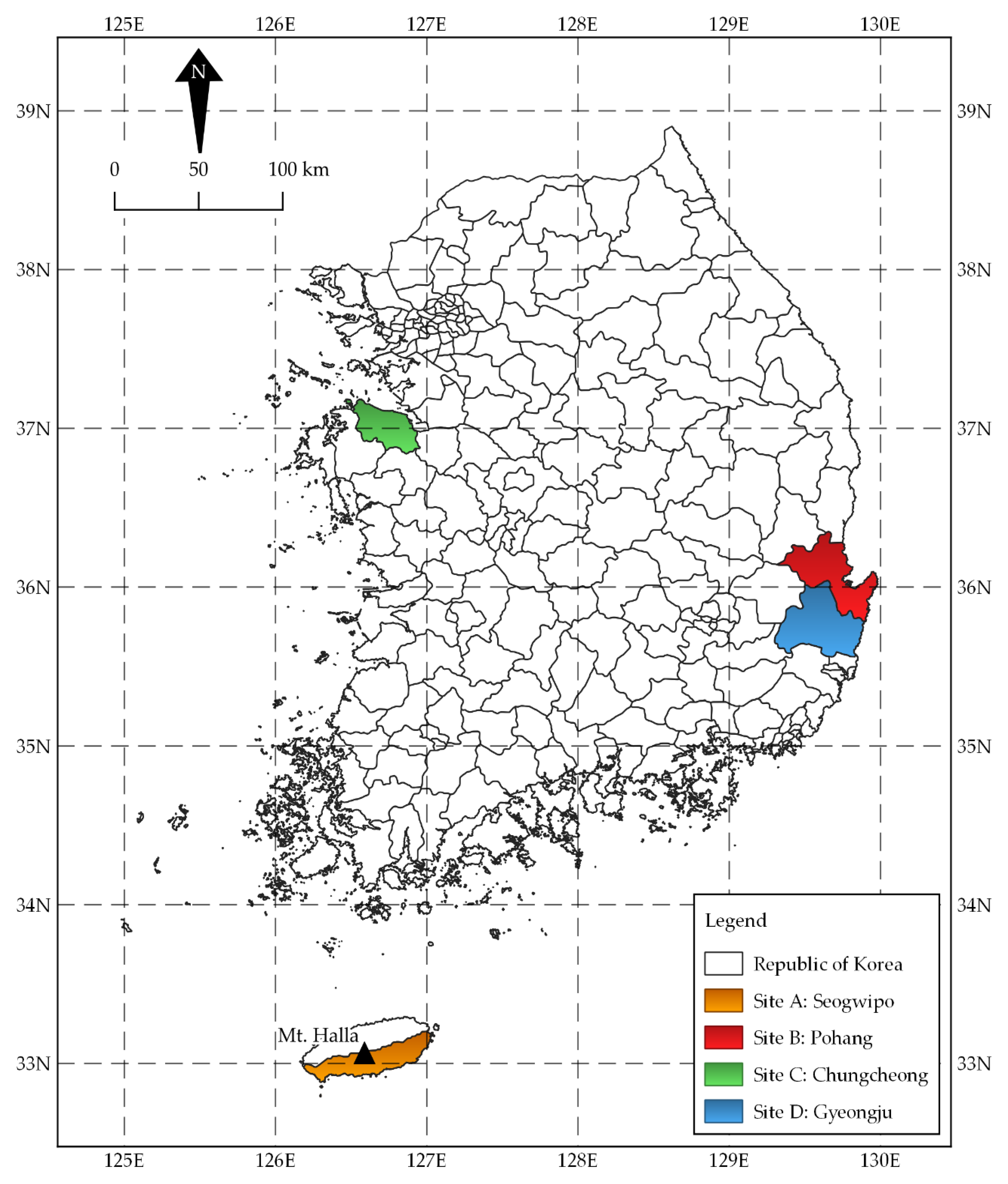
Figure 1. Map of South Korea highlighting the selected test sites for interferometry using Sentinel-1 synthetic aperture radar (SAR) data and open-source SeNtinel Application Platform (SNAP) and Stanford Method for Persistent Scatterers (StaMPS) tools.
Applsci 10 07447 g001
Figure 2. Tunnel alignment and vertical shaft location. Roads A and B intersect near the vertical shaft. Photos were taken in June 2019. Road pavement cracks (photo (e)) and masonry fences cracks (photos (c,d,g,h)) were observed during the field investigation. Path sections near the vertical shaft were either depressed or raised (photo (f)).
Applsci 10 07447 g002
Figure 3. Approximate area of slope failure and slope stabilization works. Photos (a,b) were taken in November 2019. Photos (c,d), and panoramic view were taken in August 2020.
Applsci 10 07447 g003
Figure 4. Master-slave configuration for (a) tunneling-induced ground deformation in Site C and (b) rainfall-induced landslide in Site D. The time interval between successive SAR acquisition is equal to or less than 24 days. All perpendicular baselines for each interferometric pair were less than 150 m. Each point in the graphs represents a SAR image and each line represents an interferometric pair. Horizontal and vertical axes define the temporal (BTemp) and perpendicular (BPerp) baselines, respectively.
Applsci 10 07447 g004
Figure 5. Standard repeat-pass interferometry processing workflow implemented in SNAP for digital elevation model (DEM) generation in Site A and ground deformation analysis in Site B.
Applsci 10 07447 g005
Figure 6. Advanced differential interferometric synthetic aperture radar (A-DInSAR) (based on Permanent Scatterer InSAR (PS-InSAR) technique) processing workflow through integration of SNAP and StaMPS. The workflow was implemented for tunneling-induced ground deformation monitoring in Site C and rainfall-induced landslide analysis in Site D.
Applsci 10 07447 g006
Figure 7. Quality check of InSAR-derived DEM using (a) interferometric phase and (b) interferometric coherence.
Applsci 10 07447 g007
Figure 8. InSAR-derived DEM using Sentinel-1 SAR data processed through SNAP.
Applsci 10 07447 g008
Figure 9. The maps shown were resampled to the pixel resolution of the InSAR-derived result. (a) SRTM DEM and (b) elevation difference.
Applsci 10 07447 g009
Figure 10. Comparison of elevation profile between InSAR-DEM and SRTM-DEM. (a) Section A-A’ and (b) section B-B’.
Applsci 10 07447 g010
Figure 11. Interferometric coherence map for (a) pre-seismic pair and (b) co-seismic pair.
Applsci 10 07447 g011
Figure 12. Coherence difference map. The insets of the figure show a smaller area encircled in black to highlight the detected damaged buildings using the coherence difference analysis method.
Applsci 10 07447 g012
Figure 13. Map for (a) interferometric phase and (b) ground deformation.
Applsci 10 07447 g013
Figure 14. Line-of-sight (LOS) mean velocity map.
Applsci 10 07447 g014
Figure 15. LOS displacement time series for selected PS points (a) PS-A01~A06 and (b) PS-B01~B06. The tunnel construction phases are highlighted with grey color and marked with letters A–E. The horizontal axis is presented in days measured with respect to the first SAR image.
Applsci 10 07447 g015
Figure 16. LOS mean velocity map, (a) whole study area and (b) enlarged picture of the failed slope.
Applsci 10 07447 g016
Figure 17. LOS displacement time series for selected PS points (a) PS-01~06 and (b) PS-07~12.
Applsci 10 07447 g017
Table 1. SAR dataset used.
ApplicationTest SiteMethodImage PairBTemp (Days)BPerp (m)
DEMAInSAR20180321~040212170
EarthquakeBDInSAR20171023~11041233
20171104~11161267
TunnelingCA-DInSARFigure 4a12~5761~117
LandslideDA-DInSARFigure 4b12~3721~125
Publisher’s Note: MDPI stays neutral with regard to jurisdictional claims in published maps and institutional affiliations.