1. Introduction
A laser headlight, representing the most advanced, cutting-edge and efficient vehicle lighting system, has higher illumination efficiency than halogen and xenon headlights, and its energy efficiency is also no less than that of an LED headlight [
1]. With a small size and strong penetration, laser technology has become the mainstream for next wave vehicle lighting. Since its successful development in a laboratory in 1960, laser has been considered an extremely important scientific achievement; however, it is rarely used in lighting applications [
2]. Laser automotive headlights, which exhibit the characteristics of single wavelength, high homology, high directivity and high penetration, [
3] are considered to be extremely innovative and energy efficient [
4,
5].
Advanced headlight technology such as adaptive headlighting system are timely research topics. In this paper, a proposed optical design and simulation is our present approach, aimed at not only improving the headlight efficiency with laser diode, but also supporting adaptive headlighting technologies. Generally speaking, the advantage of using a laser application in headlights is that the laser diode is only one-tenth or less the size of a conventional halogen lamp. In addition, advanced technology today significantly improves the performance of various laser diodes, which saves space and reduces power consumption further. Laser automotive headlights produce 170 lumens per watt, as opposed to the 100 lumens per watt produced by LEDs, indicating that the luminous efficiency achieved using a laser is 70% higher than that obtained using LED headlights. In terms of penetration, laser automotive headlights can penetrate as much as 600 m, which is twice the penetration achieved when using traditional halogen, xenon and LED lights, and is considered to be energy efficient in a vehicle-proven environment. Furthermore, the small size of the laser device provides a considerable degree of freedom in the design of the vehicle [
6,
7].
Laser diodes as the light source and their simulation in this proposed research could be further analyzed from the point of view of the background of the simulation software and how it works.
1.1. Background
Automotive illumination technology improved fast over the last decade and a half. As we have seen, incandescent halogen bulbs give way to high intensity discharge (HID) and light emitting diode (LED) and its related technologies. Even Audi and BMW have started to ship vehicles that use a laser-based illumination system [
8,
9] in recent days.
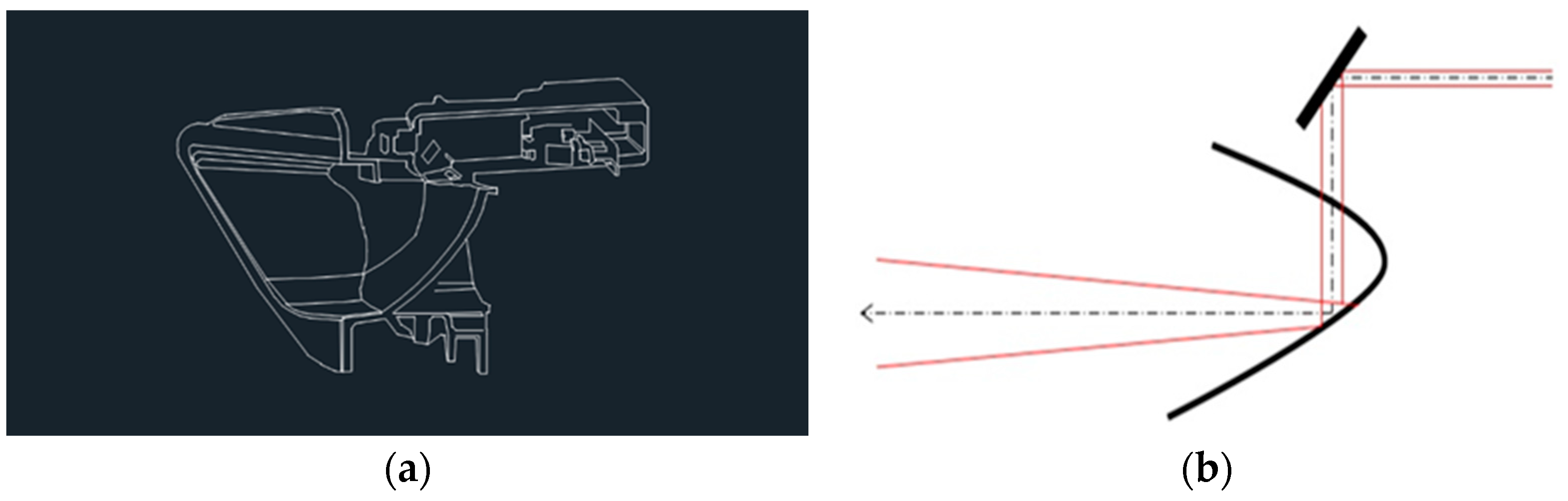
Currently, BMW has the most mature technology for the mass production of laser light modules (
Figure 1), wherein the laser source moves toward the mirror, which reflects the light on the freeform reflector lamp cup. This then diffuses and projects the laser beam over the area to be illuminated [
10]. Audi has its design performed by ultra-precise aspherical reflection surface [
11].
One of the major problems is optical design and simulation for newer lighting sources due to their optical characteristics. Furthermore, new developments in adaptive headlamp technologies and laser diode as light source become more complicated from the point view of optical system design. For example, the Audi Pixelated Laser Headlights Light employed a laser lighting system and a micro mirror device (DMD), which is very close to DLP projectors from the point view of optical design. This system can vary its lighting pattern directionally, then have its image projected on the road. In this proposed research, we have incorporated an adaptive lighting capability into our simulation of automotive Illumination with laser source [
12].
1.2. Optical Software: LightTools
In most cases, optical system design plays the role in opto-mechatronic system. Optical system design is based on ray tracing so that computer-aid design and optimization is a critical issue.
LightTools is a 3D optical engineering and design software product that supports virtual prototyping, simulation, optimization and photorealistic renderings of illumination applications. Its unique design and analysis capabilities, combined with ease of use, support for rapid design iterations and automatic system optimization, help to ensure the delivery of illumination designs according to specifications and schedule [
13].
1.3. Simulation for Laser Diode and System
It was not feasible to accurately model the laser diode that can make up a modern headlamp system. A more practical approach was to gather real world data from headlamp measurements and use that as a look-up table in our headlight model. These data employed in this research were provided by LightTools laser diode data base, which provides the luminance value for reference laser diode for simulation purposes [
13].
All proposed research work in this paper was executed by LightTools either ray tracking or optimization. Neither protype nor manufacture was done in this experiment. We might have opportunities to proceed with the prototype work in case automotive companies show their interests in further developments. Cost and light efficiency of advanced laser technology will play a role in further improvements.
In this study, a diode laser was designed as the headlight source, and a headlight optical model was constructed, together with several new optical devices, using novel optical component design concepts. The designed model could effectively diffuse a laser point source into a laser surface source. Then, light patterns of the high and low beams could be generated by controlling the liquid lens.
Section 2 introduces the concepts of the headlight optical system and the new optical devices.
Section 3 details the simulation and analysis of the headlight optical system, and evaluates whether the optical system satisfies the regulatory requirements, based on the simulation results for each device and on the overall simulation results.
Section 4 also compares the laser headlight system with the current specifications to establish whether it had performed better than anticipated.
2. Concept Design of Laser Car Headlight System
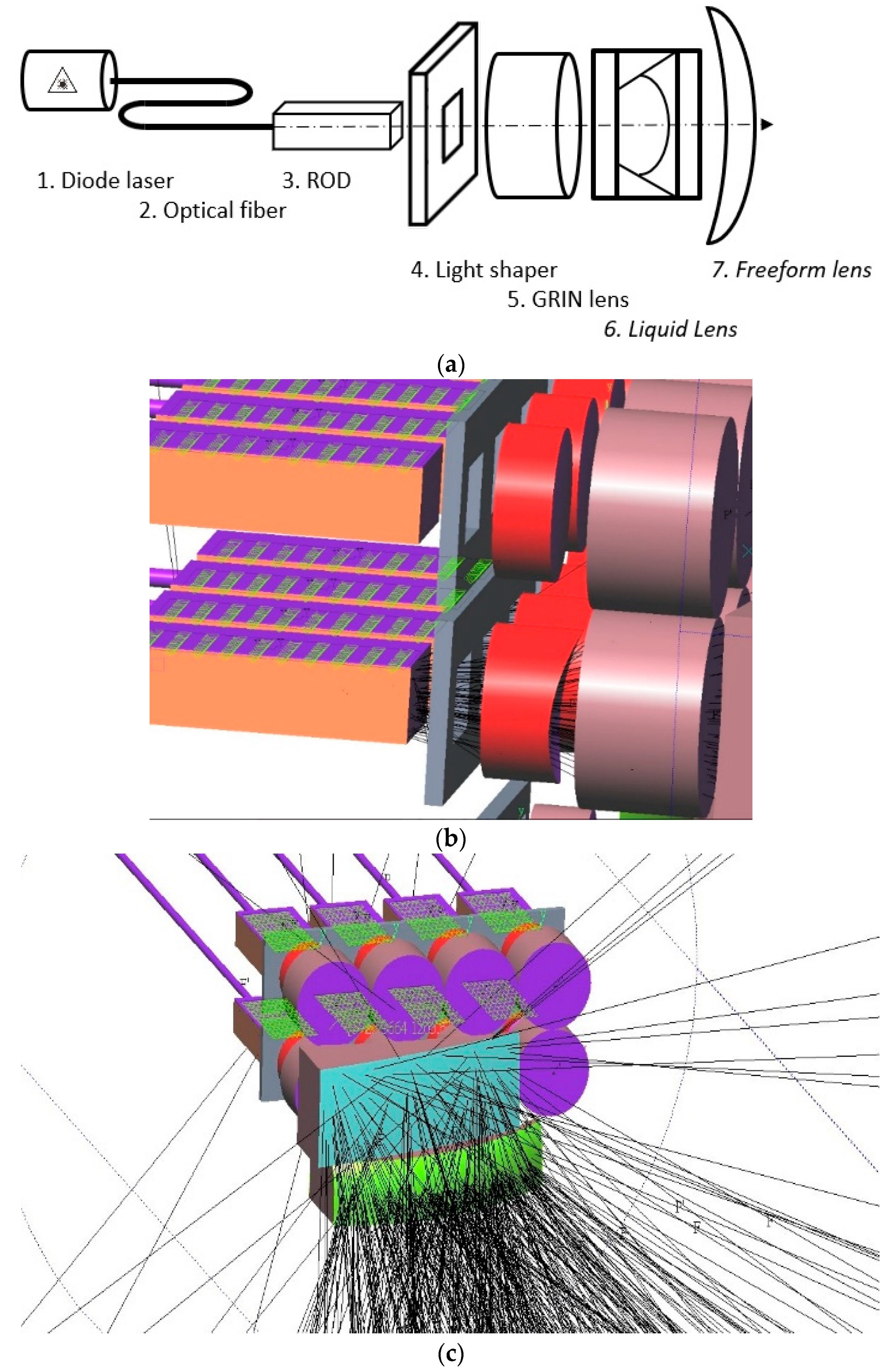
This study conceives an optical model that directly diffuses light; it does not use a mode of reflected light and it is different from the optical system used in the BMW i8 laser headlights. The purpose of designing this optical system is to minimize the amount of stray light and, therefore, reduce the loss of light energy. The laser headlight optical system comprises a laser source, an optical fiber, a ROD, a gradient-index lens (GRIN lens), a liquid lens and a freeform lens [
14,
15,
16].
Figure 2a shows the transmission of laser beams in the optical device. The concept of the optical system is one of beam diffusion. A laser outputs a high intensity, polarized, Gaussian distribution beam, which must be diffused into a surface light source to be suitable for use in lighting applications. The laser was transmitted from the laser diode to the headlight system via optical fibers that have the ability to transmit light over long distances and can eliminate the phenomenon of partially polarized light through total reflection [
8]. The laser beam was transmitted to the ROD via optical fibers, whereby the ROD rearranged the laser beam and eliminated the polarized light pattern, thus facilitating the subsequent diffusion process. The profile of the ROD’s light output was adjusted using a light shaper, which also removed excess stray light. First, the GRIN lens plays a role in the proposed optical design because the shape of the incident light is modified and optimized simultaneously to meet the specifications. Second, liquid lenses with various focal lengths can converge light from the laser source into the laser surface source to optimize the best performance between the high and low beams of the system specification. In other words, after the optimization work, the liquid lens variations in focal length may provide the best performance for either the low- or high-beam mode. According to the illuminance of the low- and high-beam modes, and the specifications of the illumination area, a freeform lens, with the function of adjusting the light pattern and illumination area, was used to satisfy the requirements of the headlight regulations. The light emitted by the laser diode was first modified by the specially designed ROD through fiber optic cables. Throughout the entire light shape (aperture stop), rays were converged via a GRIN lens, focal length and extremely complex freeform optics to deliver the best high-beam/low-beam model performance. The functions and applications of the optical devices used in this study are described below (see
Figure 2b,c for the device numbers). The above description corresponds to a single light source module; a collection of many light source modules can form an automobile light system.
The color temperature of the automobile light source is in the range of 4000–6000 K and its penetration power and lighting ability are excellent [
17]. Therefore, this study used 5500 K white lasers as the light source. No. 1 in
Figure 2 is a diode laser, which exhibits the characteristics of homochromatic, high intensity, high penetration and high-beam parallelism, and has become a new option in automobile lighting. Due to its small size and high energy conversion efficiency, a diode laser can be effectively used as the headlight source [
18,
19]. However, the disadvantage of the diode laser is that its small size makes it difficult to dissipate heat, and heat dissipation is a crucial technical consideration [
20].
No. 2 is the optical fiber that this study uses to transfer laser light. Optical fibers are flexible and can be bent to direct light to a desired location. The laser light source is small in size, which makes it difficult to dissipate heat; therefore, the laser light source is eliminated from the headlight system and an optical fiber is used to direct the light to the system. A suitable laser source heat dissipation system can, therefore, be effectively established, allowing for the maintenance of the laser light source. This study uses Ø 1 mm single-mode fiber as the optical transmission component.
No. 3 is a ROD. A ROD is an all-around surface-polished optical device, with an appearance similar to that of a cylindrical lens. It comprises a highly reflective mirror, and its function is to integrate a light source and produce a uniform light beam with a specific shape created by a ROD [
21]. Its purpose is to focus laser gaussian beam then after multiple reflection, finally form a homogenized laser light distribution. Therefore, the laser beam will become more uniform in square shape after entering a light shaper ROD, which is commonly seen in pico-laser projectors.
No. 4 is a light shaper. Its main function is to adjust the light type. To produce a clear cut-off line that satisfies the regulations, the exit light should be a square type to produce a cut-off line effect.
No. 5 is a GRIN lens. The GRIN lens is a cylindrical lens, which has different refractive indices when viewed along the lens axis, and can be used to focus or diffuse light beams. The use of GRIN lens can reduce the number of lenses required to achieve the effect of light diffusion [
22].
No. 6 is a liquid lens. Liquid lenses represent a new technology in optical devices, in which the shape of interface between the two liquids in the lens is changed by controlling the electricity. Therefore, the direction of light projection can be controlled, and the focus can be varied. The use of liquid lenses made from certain special liquids, such as disulfide, enables precise control of the focal length, where the liquid must eliminate the stray light to enable the lens to produce accurate and reliable light. In this study, a liquid lens was used as a change switch, which was capable of switching between the high and low beams by adjusting the liquid lens curvature and optical axis. This pioneering study can effectively satisfy the simplified requirements of the headlight components.
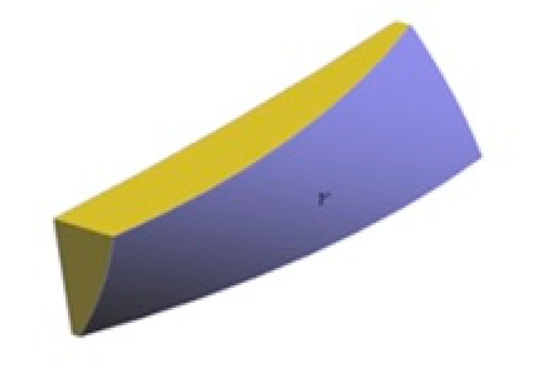
No. 7 is a freeform lens. The laser beam processed using the six optical devices described above was diffused in this study. However, the output light pattern failed to satisfy regulatory requirements. Therefore, we adjusted the output light pattern using a freeform lens, which has an aspheric surface with asymmetrical and multi-symmetric axes, and was designed using Equation (1). By controlling the curvature parameters of the X- and Y-axes of the lens, a lens with an asymmetrical pattern can be manufactured, and the projected light pattern can be changed. The shape of the freeform lens is depicted in
Figure 3.
where
, z denotes the depth from the surface to the mirror,
c denotes the central curvature of the mirror,
r denotes the perpendicular distance from any point on the mirror to the optical axis,
k denotes the conic constant (quadratic curve),
Cj denotes the monomial coefficient and
m and
n denote the powers of
x and
y terms in the polynomial series.
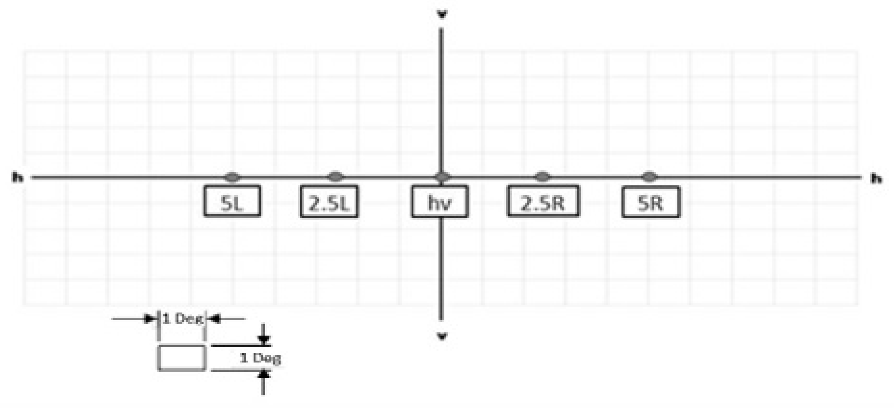
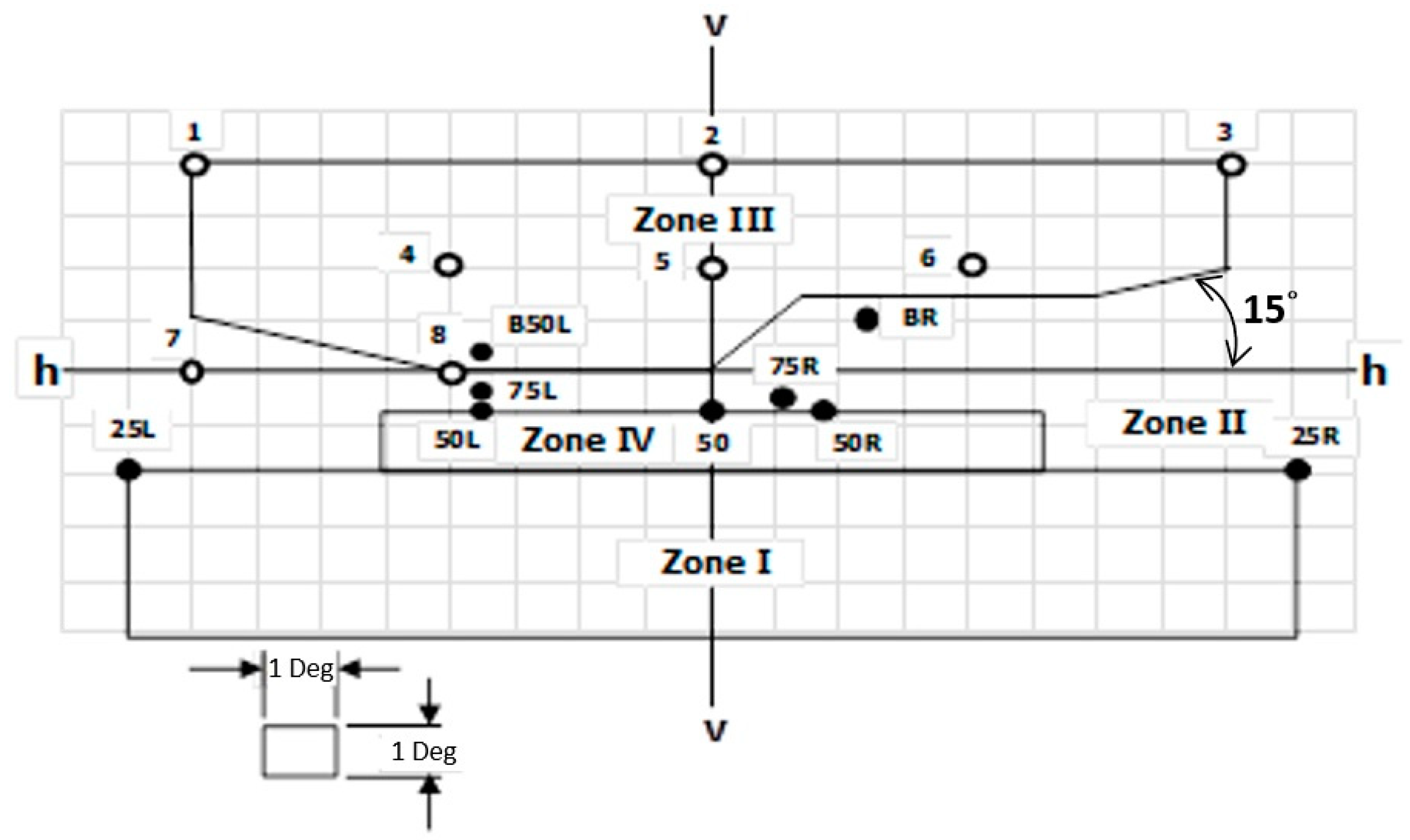
Figure 4 and
Figure 5 denote the European regulations associated with the high- and low-beam distribution range and intensity. The test configurations of the high and low beams are the same. When testing, the light source is 25 m away from the detection screen. The test environment illumination is 0 lux. For the high-beam test, the maximum illumination area needs to be located at the intersection of the h–h line and v–v line, as shown in
Figure 4. Other locations and specifications are shown in
Table 1 [
23].
When the low beam is illuminated, it is necessary for it to measure below 20 lux for Zone I, below 0.7 lux for Zone III and above 3 lux for Zone IV, as shown in
Figure 5. Zone III’s regional illumination is limited to 0.7 lux to prevent glare. The lower edge of Zone III is the cut-off line position, which must be controlled to prevent glare. The position and specification of the low-beam detection points are shown in
Figure 5. The cut-off line of the left-hand car is divided into the v–v line, and the left side is on the h–h line. The right side extends from the intersection of the h–h and v–v lines at 15° to the upper right side. Detailed specifications are shown in
Table 2.
3. Simulation and Analysis of the Headlight Optical System
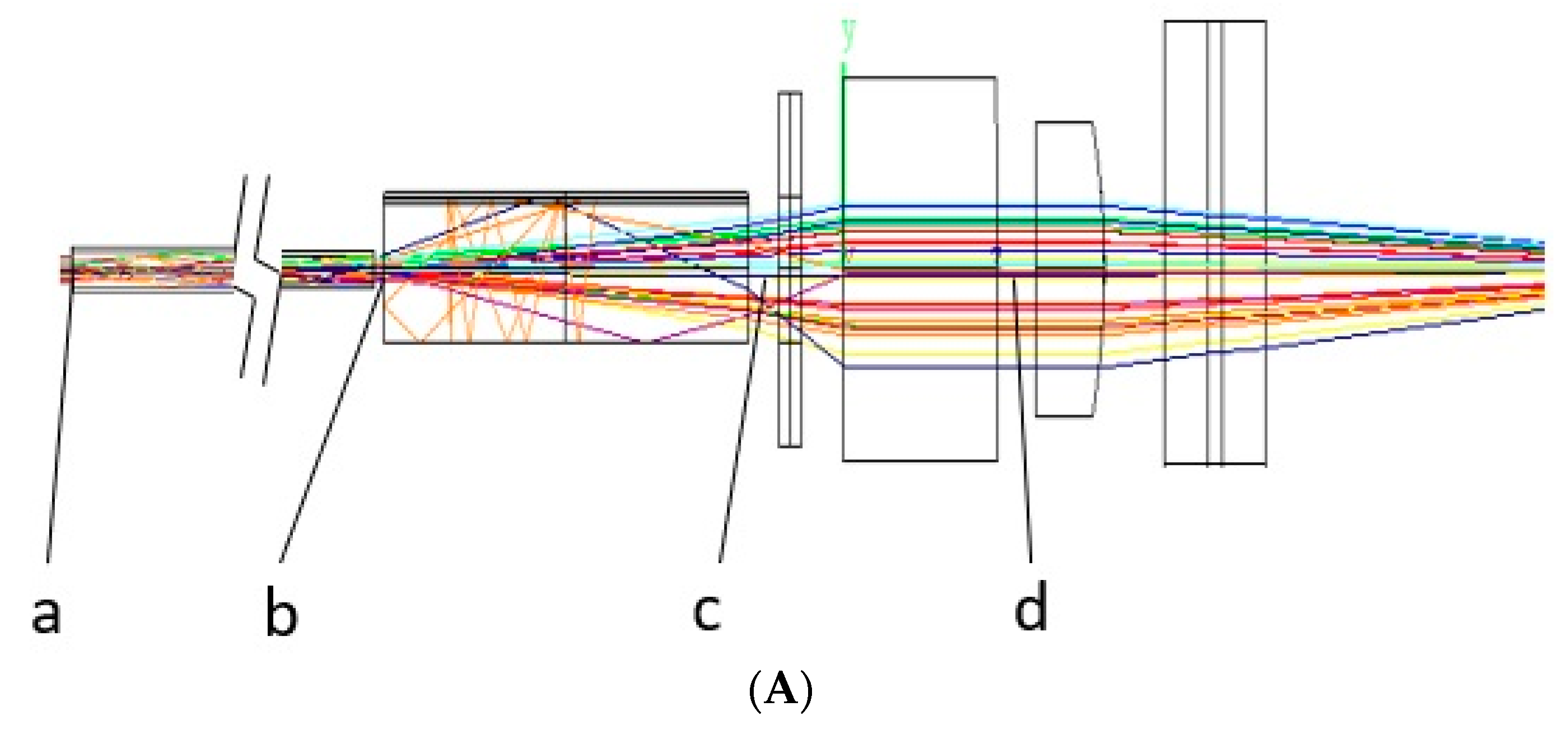
Due to the complexity of the optical system, the output light pattern from the laser source to the freeform lens requires a large number of calculations. Therefore, geometric optical theory was used to design the preliminary light propagation framework. However, the details must be verified using a finite element method. This study used LightTools
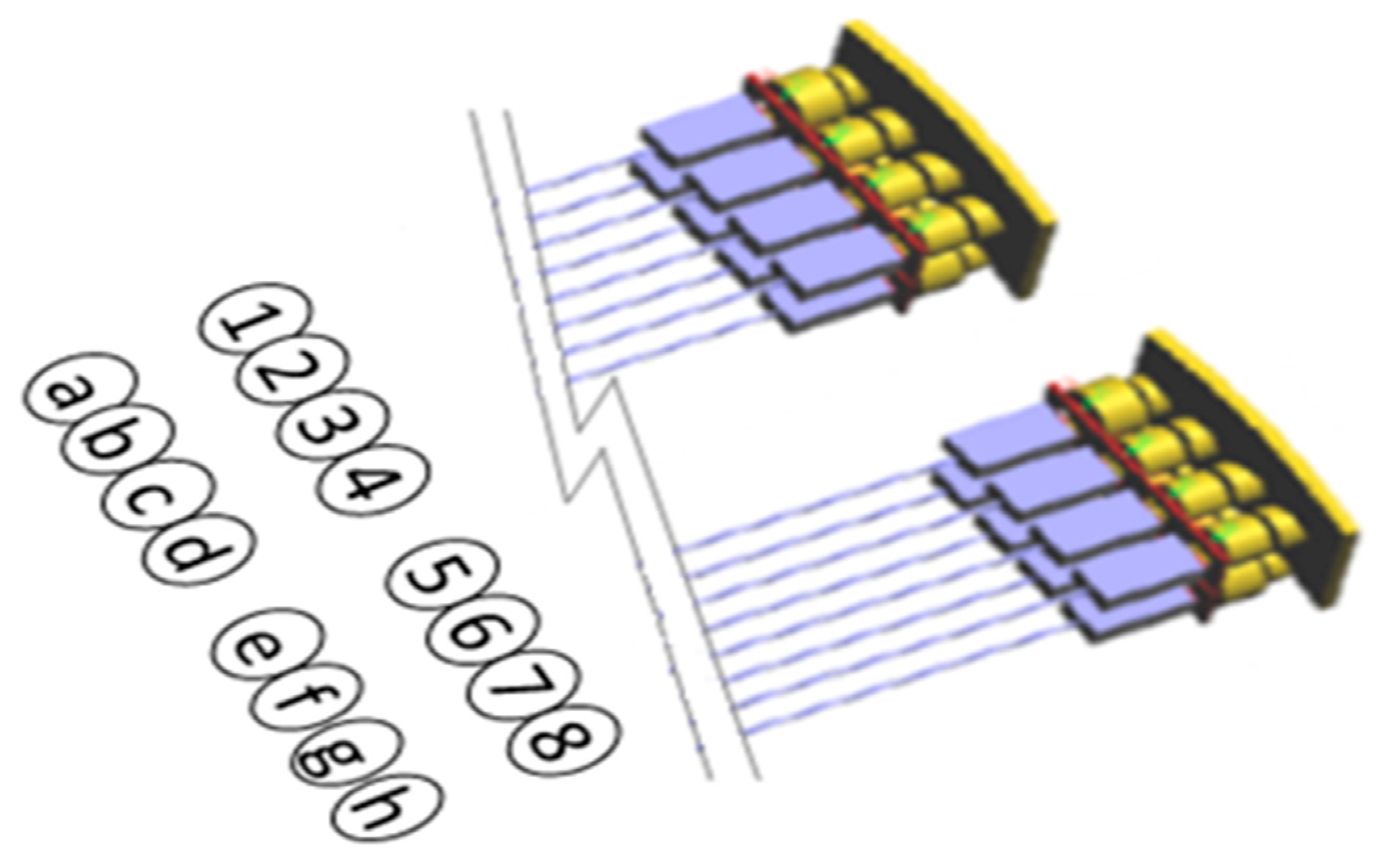
® optical simulation software to perform the necessary simulations and analysis to verify the accuracy of the optical model results. First, a three-dimensional (3D) digital model of each optical device was developed, with various parameters being assigned to the digital model, according to its optical characteristics. The optical devices were further combined into a 3D digital system based on the optical architecture that was designed in this experiment. There are two lighting modules available in this proposed system: a left and right headlight set. Each light source module was a combination of eight 1 W white diode lasers in a 4 × 2 array. There was a total of 16 laser sources; therefore, the total power of the laser source was 16 W. All laser sources were numbered (see
Figure 6).
The ray trace analysis of the optical system is shown in
Figure 7A. Each chart below shows the different light source distribution on each image plane after simulation to achieve light efficiency [
24,
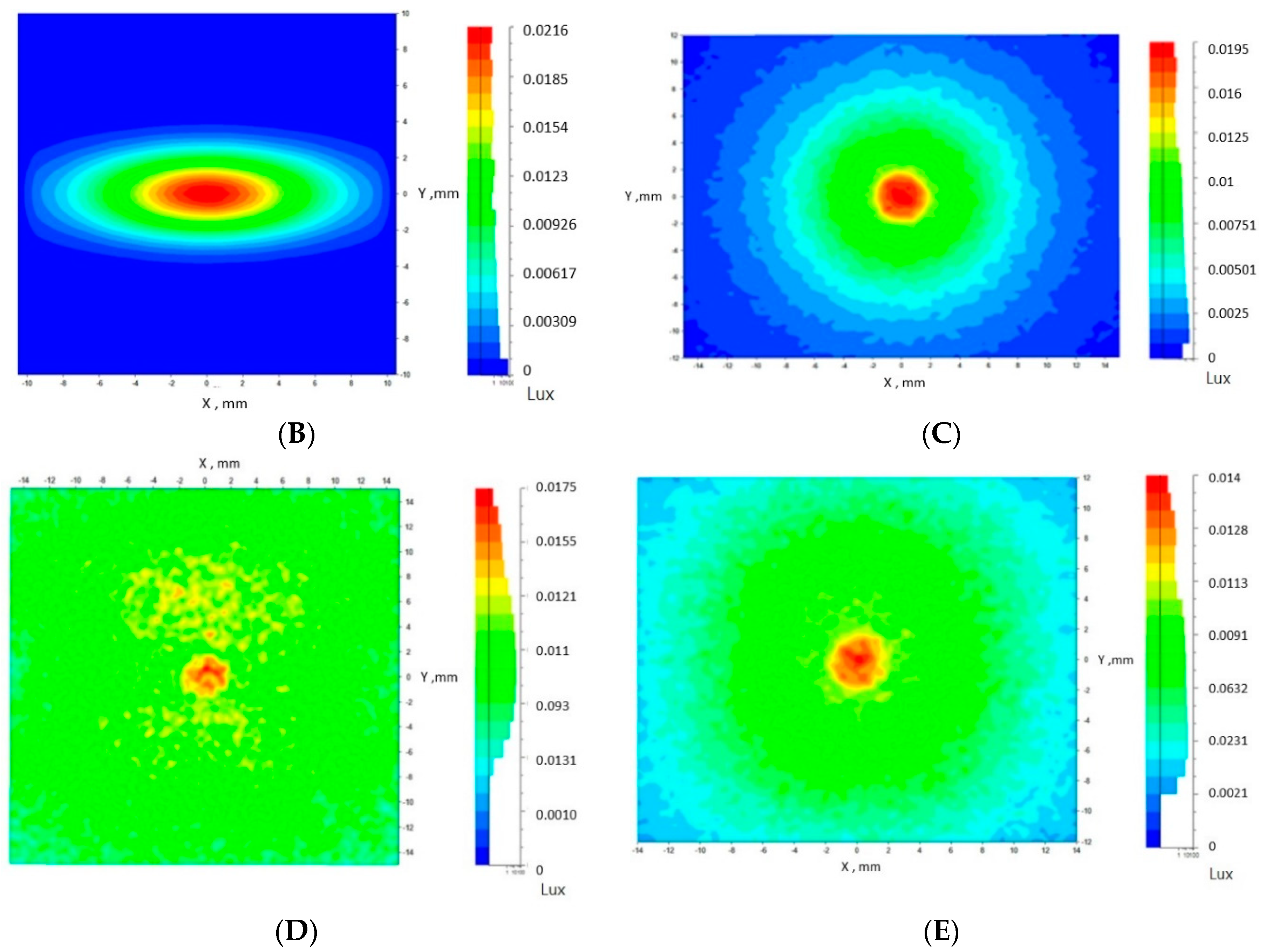
25]. The laser is a Gaussian light source, and the light intensity at the middle point is the strongest. The Gaussian distribution of light intensity in X and Y directions is different (
Figure 7B). Laser transmission through the optical fiber significantly improved laser polarization.
Figure 7C shows the light pattern simulation of the fiber exit side, which indicates the effectiveness of improving polarized light. The intensity of the laser light output from the optical fiber was still concentrated; however, the polarization of the laser beam was eliminated after it entered the ROD, which performed an optical adjustment. In addition, the light intensity was uniformly diffused.
Figure 7D shows the light pattern on the ROD exit side, indicating the results of the homogenization of laser diffusion and the elimination of polarization. After the periphery of the light beam output from the ROD was adjusted using the light shaper, eliminating stray light and shaping the beam, the light beam entered the GRIN lens for diffusion. Show in
Figure 7E.
Firstly, in this experiment, we find the right laser diode and its LightTools file from LightTools database. Secondly, we find some fiber files from LightTools database. They are files with all fixed data so these are not able to be optimized. If laser diode is determined like in
Figure 7B, fiber will be selected in order to achieve best performance according to light efficiency, basically like in
Figure 7C. Generally speaking, fiber and laser diode both are selected before optimization procedure in order to match of optical components each other’s, which is nothing to do with later optimization.
The parameters of optimization with regard to this system are following:
- (1)
ROD variables: total length; width and height in order to reach best light efficiency in
Figure 7D.
- (2)
GRIN optics variables: GRIN index from polar coordinates on optical axis and its thickness. In order to reach uniformity in
Figure 7E.
- (3)
Freeform optics variables: Radius and off-axis X and Y coefficients in order to achieve best results inclusive of light efficiency, uniformity and the most important, match the safety requirement ECE R-112 in
Figure 8 and
Figure 9.
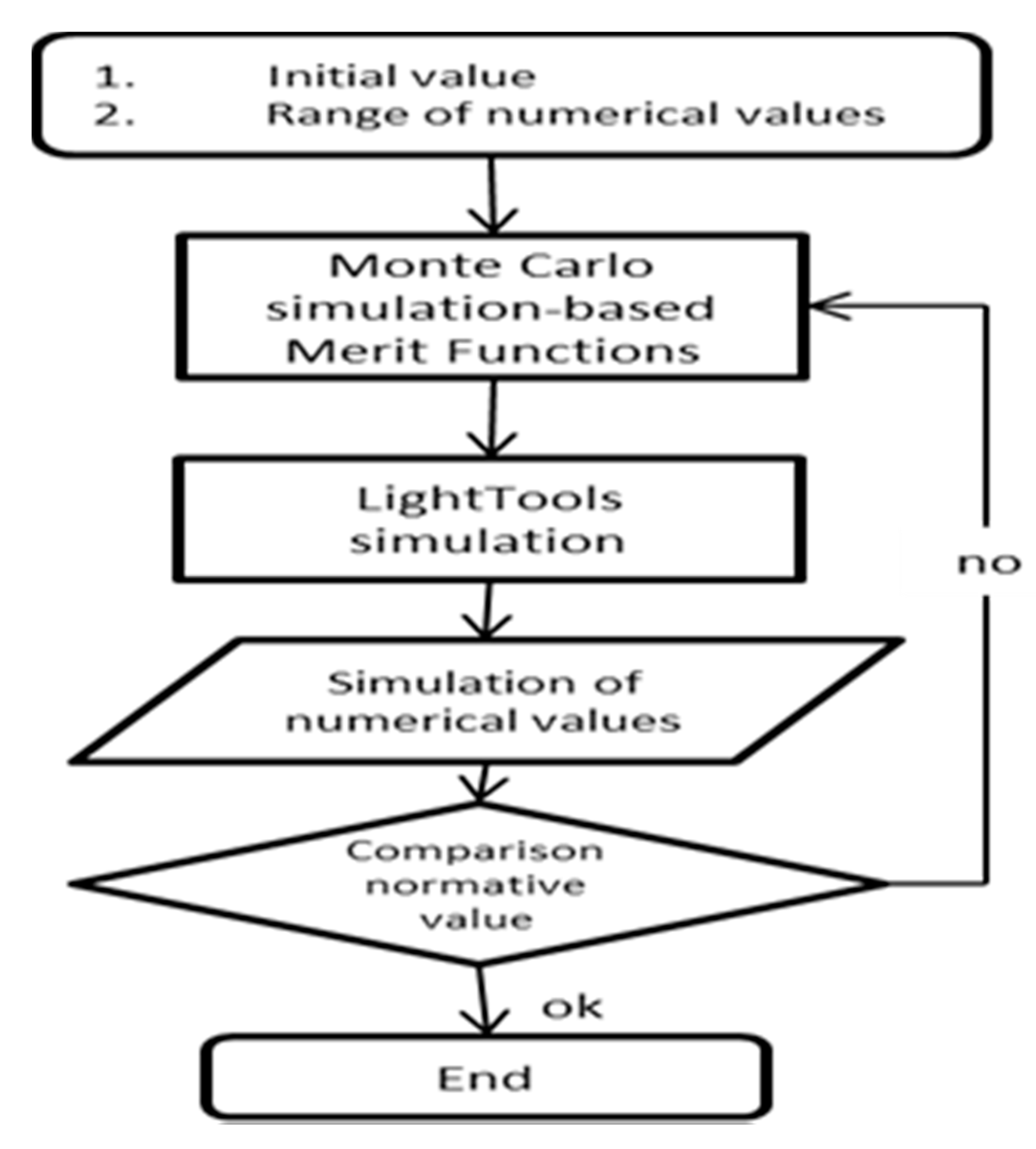
Next, the diffused laser beam entered the liquid lens to enable switching between the high and low beams, wherein the liquid lens curvature and optical axis were changed. The freeform lens was made of Kopp Sharp CutRed 2424 glass. Due to effect of complicated annealing process during freeform manufacture, only very few optical glass in the current market is feasible for this project. CutRed 2424 glass is always strongly recommended for this kind of project. It has a curved surface shape, which was constructed by Equation (1). Adjusting the parameters to values that satisfy the regulations is time consuming and labor intensive. Therefore, we employed an automated program, in which the Monte Carlo method was used as the optimization engine to iteratively optimize surface parameters.
Figure 10 shows the automated optimization process. First, the initial values of the parameters in Equation (1) were set, and the range of parameter value intervals was given. Then, the surface position and illuminance values detected according to the regulations were set as the optimization target values. The Monte Carlo method employed by LightTools for the basic theory of ray tracking was used to conduct an iterative operation using an automatic random sampling technique to determine optimal surface parameters, which could be obtained with a certain number of iterations [
25].
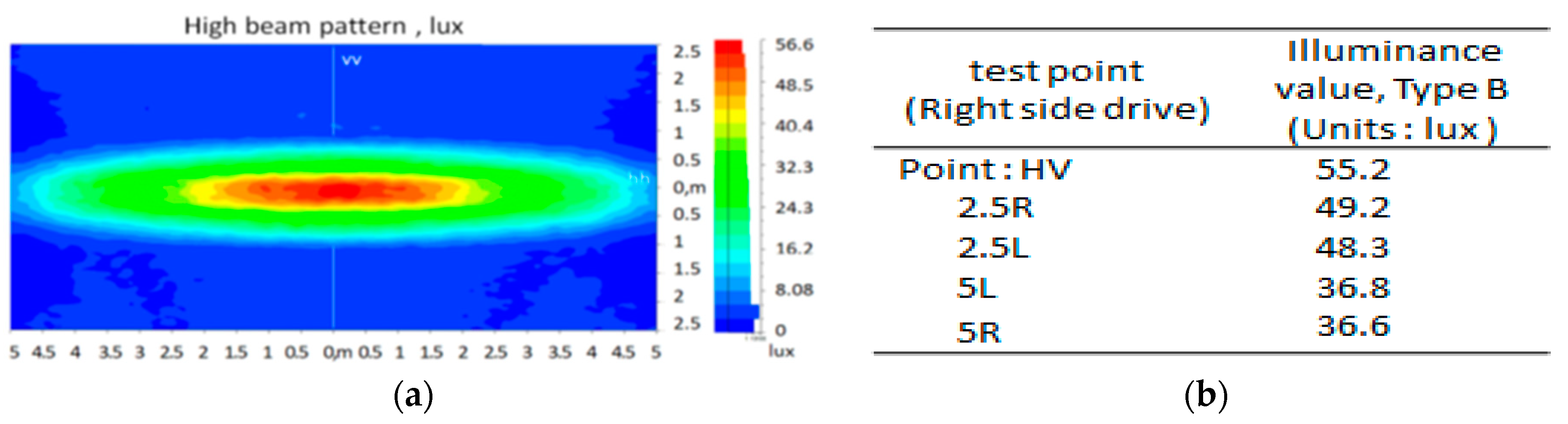
In this experiment, the high-beam system had eight laser sources (a, b, c, d, e, f, g, h) turned on, with a total power of 6.4 W for high beam after reduction of system light loss due to not perfection of light efficiency. The experimental data of the high-beam detection points are shown in
Figure 8b. The maximum illumination was 55.2 lux, as shown in
Figure 8a, which satisfies the high-beam regulation requirements.
Liquid optics does not intend to join the full optimization described in
Figure 8 only because it is a switch for high beam/low beam. Why not join full optimization in order to achieve best performance for high beam/low beam? It is only because liquid optics is intended to be with aspherical surface which is subject to gravity. We are not able to find the right coefficient to have it optimized.
The low-beam lights turned on nine laser sources (2, 3, 4, 5, 6, 7, 8, e, f), with a total power of 4.5 W. Zones I, III and IV had an average illuminance of 20, 0.7 and 17.7 lux, respectively. The light distribution of the low beam is shown in
Figure 9a, and detailed experimental data are shown in
Figure 9b. The detection point values comply with the specifications, and the cut-off line is also within the specified range.
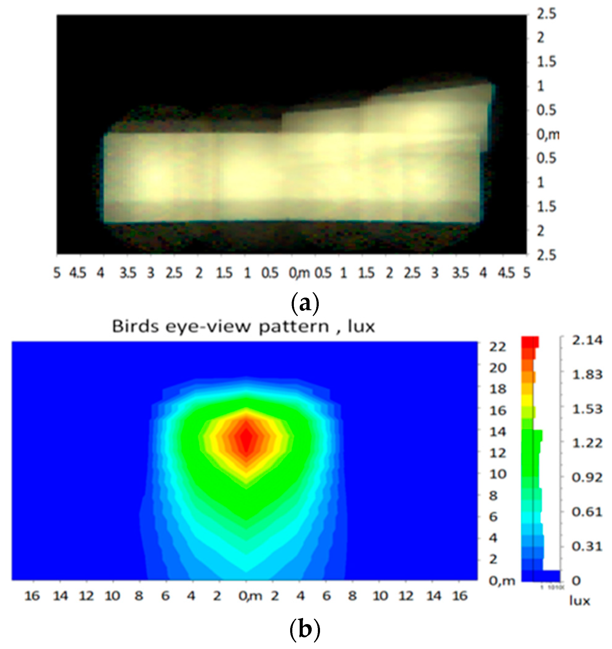
Figure 11a shows the illumination simulation results, which indicates that the cut-off line is within the specified range.
Figure 11b shows a bird’s eye view of the low beam. To prevent glare, the illumination of Zone III was limited to 0.7 lux, and the height of the cut-off line could not exceed the regulations. The above two conditions of this experiment are within prescribed values, which can effectively prevent glare and the headlight system used modular control. In addition to reducing the laser source power, the cut-off line height could be adjusted to more effectively prevent glare.
During the optimization process, as soon as the proposed optical design was set up ready in LightTools, the simple ray tracking method will start first, then following LightTool’s multiple ray-tracking optimization. If the result is not good, cease then repeat the setting work; restart again for next set up and optimization. Simulation result will be determined after optimization. The experimental simulation proves that, for the high-beam mode, the laser beam passing through the liquid lens was the output of the freeform lens, which fine-tuned the light beam. Consequently, the final high-beam patterns were obtained on the detection surface, as shown in
Figure 9a, indicating that the high-beam pattern satisfied the regulatory requirements.
Figure 9b shows the corresponding experimental values. The value of each detection point is greater than the regulatory value, suggesting that the optical system of the high-beam mode was in line with expectations. The experimental simulation of the low-beam mode is displayed in
Figure 10, suggesting that the output light pattern also satisfied regulatory requirements. The experimental values, shown in
Figure 10, were also superior to the regulatory standards, thereby experimentally verifying that the optical system devised in this study is feasible, as shown in
Figure 11.
4. Conclusions
Diode lasers demonstrate outstanding performance in automotive lighting applications because of their excellent characteristics. The optical system application that was devised as an automotive lighting solution was verified in this study using a simulation. This proposed research method is simply a simulation of the system, not actually implemented for reasons related to costs of the experimentation. The following conclusions can be drawn:
Optical fibers exhibit an excellent performance in terms of laser beam transmission. Along with the capability to transmit light, ROD can adjust the polarization of laser light to achieve precise light pattern control. Using the optical fiber application, the laser sources can be freely configured outside the optical system, which is helpful when dissipating the heat of the laser source.
Optical fibers and RODs, which are capable of effectively and accurately adjusting the laser light pattern, can homogenize the laser light through total reflection and eliminate laser light polarization, thereby influencing the light pattern adjustment.
The functions of a liquid lens can be used to easily satisfy the demand for switching between the high beam and low beam. If the light pattern is controlled by the array module, it can meet the functional requirements related to the lighting of a specific area.
The use of freeform lenses to adjust the light pattern provides the perfect balance between the aesthetic requirements of a vehicle and its functional lighting requirements. In addition, the beam pattern of the diffused laser can satisfy the regulatory requirements for aesthetic and practical purposes after performing adjustments with a freeform lens.
The headlight optical system designed in this study satisfied the regulatory requirements, both in terms of uniformity and illumination. The maximum illuminance is 56.6 lux in the high-beam mode, which is 18% higher than the standard value (48 lux).
In the low-beam mode, the illuminance meets regulatory standards. Compared with a 24 W LED headlight module, this design saves 33% more energy. This power of this design is 16 W.
If combined with opto-mechatronic control and integration, this system could increase or decrease the illumination in a specific area, thus providing a feasible solution for headlight optical systems.

 ,
, 


