Abstract
Ankle foot orthosis (AFO) is widely used to prevent foot drop and improve walking ability for individuals with cerebral palsy and stroke. However, traditional anterior AFO (TAAFO) could only last within months because the bilateral neck of TAAFO was easy to break. Currently, a 3D-printing technique is used to develop assistive devices for rehabilitation. The study aimed to implement the finite element (FE) method to revise the 3D printed AAFO (3DP-AAFO) and evaluate its strength. A 3.2 mm-thickness for the TAAFOs and 3DP-AAFOs were fabricated, respectively. The stiffness of TAAFO and 3DP-AAFO were tested by a material machine and compared to the FE model. In the FE analysis, the thickness of AAFO model was increased at the neck to enhance its strength. A plantarflexion and dorsiflexion moment were respectively subjected to 3DP-AAFO models to undergo stress analysis. Under the mechanical test, the 3DP-AAFO (K = 1.09 Nm/degree) was 7.8 times stiffer than the traditional AAFO (K = 0.14 Nm/degree). The FE results showed that thickening the 3DP-AAFO on the neck up to 4.7 mm could moderate stress concentration and increase the stiffness of the 3DP-AAFO. Therefore, the study concluded that the 3DP-AAFO was stiffer than the traditional AAFO. Increasing the appropriate thickness around neck of 3DP-AAFO could avoid neck fracture as much as possible.
1. Introduction
Neuromuscular and musculoskeletal disorders such as stroke or cerebral palsy can cause great difficulty in ambulation [1]. Lower limb orthoses such as ankle foot orthoses (AFOs) have been used to correct the ankle position, provide stability, and assist limb clearance [2,3,4,5]. Using an AFO can improve an individual’s balance, toe clearance during swing phase, gait performance, and mobility, immediately leading to improvement in an individual’s activities of daily living [6,7,8,9,10].
Anterior type of ankle foot orthoses (AAFOs) are widely used in Asia, because they are suitable for walking [11]. AAFOs are designed in the anterior leaf type and support the foot from the metatarsal head. These types of AFO can be fabricated quickly and easily. However, due to the strength of the material properties, AAFOs can only be used for patients with less plantar spasticity. This material was found to be less durable and only lasted within a few months [12]. Moreover, pre-fabricated AAFOs could also cause some patients to complain about bruises on bony land marks [13].
Currently, 3D-printing techniques can be applied to patients with different conditions. This technique has been recognized as a feasible way to improve customized AFOs. Common 3D printing techniques including selective laser sintering (SLS) and fused deposition modelling (FDM) have been used to fabricate customized orthoses. These techniques can fabricate not only customized products, but also special designs, revising the product that causes the products to become stiffer [14]. Previous research on 3D printing AFOs (3DP-AFO) has mainly been based on SLS [15,16] and fewer AFOs have been produced by FDM. However, the cost of SLS products is relatively high and time consuming; and FDM products are mostly used in manufacturing of posterior-type AFOs (PAFOs). Additionally, the previous study mostly focused on the evaluation of 3D printing PAFOs rather than 3D printing anterior AFOs (3DP-AAFOs). Therefore, this study conducted FDM to fabricate 3DP-AAFOs. In order to understand whether the 3DP-AAFOs were strong enough to support individuals, mechanical tests were applied on the 3DP-AAFOs. Additionally, a past study implemented finite element (FE) analysis to predict the mechanical behavior of AFOs and found that the FE analysis could predict the weakness of the AFO [17]. Darwitch et al. [18] addressed that focusing on the design and analysis of AFOs using FE analysis could increase the patient’s comfort. Ielapi et al. [19] reported that the error between the experiment and FE simulation should be controlled within 10% in the FE analysis of AFOs. These studies show the potential to improve the performance of AFOs. Therefore, this study aimed to conduct a FE model to evaluate 3DP-AAFOs and also enforce its strength based on FE analysis.
2. Material and Methods
2.1. Manufacturing of 3DP-AAFOs
Fifteen traditional AAFOs (TAAFO) and fifteen 3DP-AAFOs were respectively fabricated. The 3DP-AAFO was fabricated from a solid foot model. The software Cura (Ultimaker, Inc., Geldermalsen, The Netherlands) was used to slice solid models and were printed in polylactide (PLA) material, as shown in the Figure 1. The printing parameters were 0.2 mm in layer thickness, 100% in density, 205° in printing temperature, and 60 mm/s in printing speed. A 3DP-AAFO was fabricated in seventeen hours and weighed about 118 g. In this work, traditional thermoplastic materials (polypropylene) were used for manufacturing traditional AAFOs.
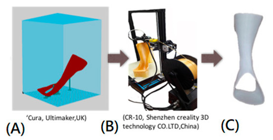
Figure 1.
The 3D printing process: (A) Slicing the AAFO model. (B) Printing 3DP-AAFO in the CR 10 printer. (C) 3DP-AAFO after cleaning all supports.
2.2. Mechanical Testing
To realize the difference between the TAAFO and the 3DP-AAFO, mechanical testing was conducted in terms of stiffness and ultimate load. Fifteen degrees of plantarflexion was given to all AAFOs [19] to measure the stiffness using the material testing machine (HT-2402 Computer Servo Control Material Testing Machine, Hung-ta Co. Ltd., Taichung, Taiwan). An indenter slowly moved at a constant rate (20 N/min). The AAFOs were also loaded through the full range of motion until the AAFOs were broken to measure the ultimate load [12]. The vertical displacements of the AFOs were recorded from the load cell, as shown in Figure 2.
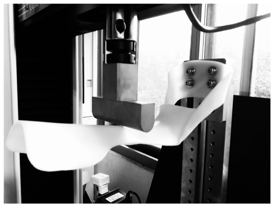
Figure 2.
Mechanical testing of the AAFO in the simulation of plantarflexion.
2.3. Finite Element (FE) Analysis
The FE software ANSYS workbench 14.5 (ANSYS Inc., Canonsburg, PA, USA) was implemented in the study. The PLA material was set up with a Young’s modulus of 3500 MPa and a Poisson ratio of 0.36 for the FE model of 3DP-AAFO [20]. The FE model was simulated using solid elements in 12,722 elements and 24,848 nodes, as shown in Figure 3. The bottom of the 3DP-AAFO model was fixed completely. Under the same loading condition as the mechanical testing, the moment was subjected to the FE model to produce 15° of plantarflexion. For the FE model validation, the displacement was compared between the FE analysis and mechanical testing under a given moment 16.7 Nm (15° in plantarflexion). As to the displacement, the 3DP-AAFO model was calculated in 29.2 mm in FE analysis, and the TAAFO specimen was measured at 27.9 mm in the mechanical test. The difference of the displacement was only controlled in 4.7%. Therefore, the 3DP-AFFO model was validated. The original thickness of the 3DP-AAFO was 3.2 mm. To increase its strength, the AAFO model was thickened on the neck in terms of 0.5 mm, 1.0 mm, 1.5 mm, and 2.0 mm, as shown in Figure 4. Apart from the plantarflexion, 15° of dorsiflexion was also applied to the 3DP-AAFO model. Since 3D printing products of additive manufacturing tend to be fractured in tensile force, the study collected the maximum principal stress for comparing the different FE models.
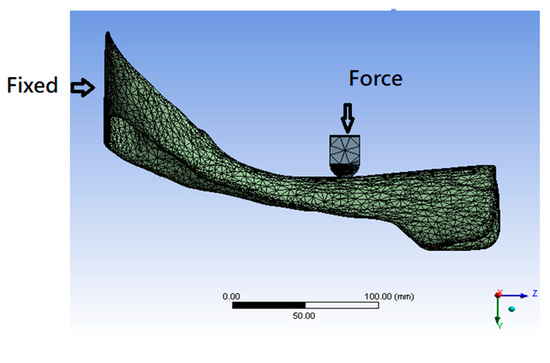
Figure 3.
Finite element model of AAFO with the indenter.
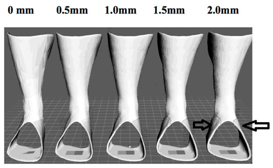
Figure 4.
Different thicknesses around the neck of five AAFO models. The arrow indicates the location of increasing thickness.
3. Results
3.1. Mechanical Testing
In the 15° of plantarflexion, the moment of the 3DP-AAFOs (16.47 ± 1.21 Nm) was greater than that of the TAAFOs (2.13 ± 0.24 Nm). This means that the 3DP-AAFOs (K = 1.09 Nm/degree) were stiffer than the TAAFOs (K = 0.14 Nm/degree) and both exhibited a linear behavior, as shown in Figure 5.
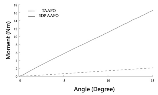
Figure 5.
Comparison of stiffness in the TAAFO and 3DP-AAFOs.
In the test of ultimate load, the moment of 3DP-AAFO was 27.65 ± 2.28 Nm. Most 3DP-AAFOs were fractured on the neck, as shown in Figure 6. However, there was no fracture in the TAAFOs since the traditional thermoplastic material has greater flexibility and ductility.
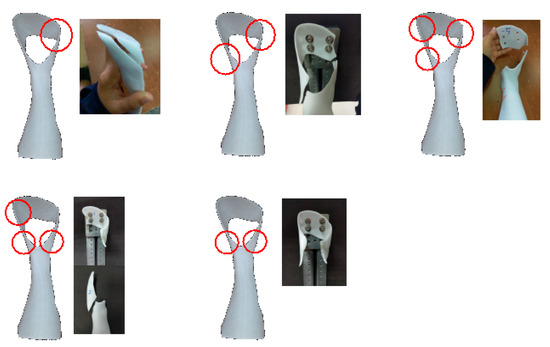
Figure 6.
Different patterns of the fractured 3DP-AAFOs. Circle indicates the locations of the fracture.
3.2. FE Analysis
The 3D printing product usually fractures in the direction of tensile force, so the study mainly took account of the maximum principal stress in the FE analysis. The stress of the 3DP-AAFO was reduced following increased thickness on the neck, as listed in Table 1. When the thickness of the 3DP-AAFO reached 4.7 mm, the displacement and stress reduced about 22% and 26%, respectively, compared to the original 3DP-AAFO model (3.2 mm). The FE results showed stress concentrated on the neck of the 3DP-AAFO, especially on the medial side (Figure 7), which showed that the region of higher stress was reduced after increasing its thickness.

Table 1.
Comparison of the maximum principal stress and the maximum displacement in different thicknesses of the 3DP-AAFOs at the neck.
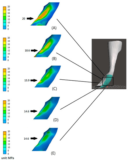
Figure 7.
Stress distribution of the 3DP-AAFOs with different thicknesses around the neck in plantarflexion (A) 3.2 mm, (B) 3.7 mm, (C) 4.2 mm, (D) 4.7 mm, and (E) 5.2 mm. Note: Arrows indicate the location of the maximum stress.
4. Discussion
AFOs are widely used for patients with the stroke, cerebral palsy, and neuromuscular disorders. Previous study has mostly focused on tests of PAFOs [15,16,17], rather than AAFOs. Compared to PAFOs, the AAFO has a lesser volume and is more suitable for the development of 3D printing. However, the AAFOs tended to fracture at the neck during walking within two months. If a 3DP-AAFO is expected to be developed for a patient, then the mechanical strength is important to realize. To figure out the mechanical properties of the 3DP-AAFO, the mechanical test and FE analysis were conducted in the study.
In the mechanical test, the 3DP-AAFOs were stiffer than the TAAFOs due to the discrepancy of material properties. Bregman et al., in 2009 [21], reported that the stiffness of AFO should range from 0.20 to 1.56 Nm/degree to provide ankle stability and prevent drop foot. In this study, the stiffness of 3DP-AAFO (1.09 Nm/degree) was within the range, but the stiffness of TAAFO was slightly smaller than the recommended range. In the ultimate load test, TAAFOs only exhibited remarkable deformation without any fracture because of the behavior of the thermoplastic material. However, 3DP-AAFOs were fractured at the bilateral neck in ankle plantarflexion (28.65 ± 6.2°). During most activities of daily living, normal people just walk in 20° of plantarflexion. Furthermore, the individuals with hemiplegia move in 10° of plantarflexion, which indicates that it is safe to use 3DP-AAFOs in daily life without fracture. Overall, 3DP-AAFOs offer more ankle stability than TAAFOs. Additionally, in the ultimate load test, 85% of 3DP-AAFOs fractured at the bilateral neck, which was the same as the clinical observation. Only 15% of all specimens fractured at the base and shank of the 3DP-AAFO. This means that an unexpected fracture is possible in the base of the 3DP-AAFO. The reason for early fracture can be attributed to the process of additive manufacturing. The strength of the 3DP-AAFO was influenced by the printing orientation of the 3DP-AAFO. The fused line between the different layers was weak, and easily torn from the tensile force. As a result, unsmooth surfaces or some gaps appearing on the neck or base in the 3DP-AAFO should be carefully checked.
According to the FE results, the thicker the neck of the 3DP-AAFO, the stiffer the 3DP-AAFO was. This study found that the 4.7 mm-thickness of the 3DP-AAFO would obtain a better stiffness. However, in dorsiflexion, the 3DP-AAFO with a 5.2 mm-thickness demonstrated a decrease in stiffness and increase in stress. The reason could be attributed to locally thicken the neck and result in stress concentration due to a discrepancy in thickness between the neck and base. Therefore, the sudden change between small and larger areas should be avoided. If this is not avoidable, the remarkable area change around the neck should be smoothed to moderate stress. Additionally, if the neck of the 3DP-AAFO is too thick, it is inconvenient to wear the 3DP-AAFO and the patient will choose shoes. As a result, this study does not recommend the application of a 3DP-AAFO with a 5.2 mm-thickness.
Regarding the limitation of the study, the FE analysis only considered the model in an isotropic material, but the real 3DP-AAFO is anisotropic and in-homogenous. This study underwent a static test rather than a dynamic test, so a fatigue or impact test is needed to figure out its dynamic response. Moreover, additive manufacturing is different from the machining manufacture because it existed in pore distributions in the process of 3D printing. Some nondestructive tests or nanoindentation analyses [22] can be considered to examine the hardness or effective modulus of 3DP-AAFO in future study. Before using the 3DP-AAFO, an evaluation of a patient’s spasticity is important. In the clinic, the physical therapist should consider the patient’s spasticity to fabricate the 3DP-AAFO. This study offers valuable results for the physical therapist to fabricate a 3DP-AAFO.
5. Conclusions
The study concluded that the 3DP-AAFOs were stiffer than the TAAFOs in mechanical tests. The FE analysis estimated that thickening 3DP-AAFO on the neck up to 4.7 mm could moderate stress concentration and increase the stiffness of the 3DP-AAFO. Therefore, adjusting the thickness of the 3DP-AAFO on the neck could effectively enhance its strength.
Author Contributions
Conceptualization, C.-S.C.; methodology, C.-S.C. and Y.-C.L.; investigation, Y.-C.L. and L.-Y.H.; resources, C.-S.C.; writing—original draft preparation, Y.-C.L. and L.-Y.H.; writing—review and editing, C.-S.C.; supervision, C.-S.C.; All authors have read and agreed to the published version of the manuscript.
Funding
The study was partly supported by a Grant (MOST 109-2221-E-010-009-MY2) from the Ministry of Science and Technology.
Conflicts of Interest
The authors declare no conflict of interest.
References
- Halar, E.; Cardenas, D. Ankle foot orthoses: Clinical implications. Phys. Med. Rehabil. State Art Rev. 1987, 1, 45–66. [Google Scholar]
- Rao, N.; Aruin, A. Role of ankle foot orthoses in functional stability of individuals with stroke. Disabil. Rehabil. Assist. Technol. 2016, 11, 595–598. [Google Scholar] [CrossRef] [PubMed]
- Harlaar, J.; Brehm, M.; Becher, J.G.; Bregman, D.J.; Buurke, J.; Holtkamp, F.; De Groot, V.; Nollet, F. Studies examining the efficacy of ankle foot orthoses should report activity level and mechanical evidence. Prosthet. Orthot. Int. 2010, 34, 327–335. [Google Scholar] [CrossRef] [PubMed]
- Pomeranz, B.; Adler, U.; Shenoy, N.; Macaluso, C.; Parikh, S. Prosthetics and orthotics for the older adult with a physical disability. Clin. Geriatr. Med. 2006, 22, 377–394. [Google Scholar] [CrossRef]
- Esquenazi, A.; Hirai, B. Assessment of gait and orthotic prescription. Phys. Med. Rehabil. Clin. N. Am. 1991, 2, 473–485. [Google Scholar] [CrossRef]
- Bregman, D.J.; De Groot, V.; Van Diggele, P.; Meulman, H.; Houdijk, H.; Harlaar, J. Polypropylene ankle foot orthoses to overcome drop-foot gait in central neurological patients: A mechanical and functional evaluation. Prosthet. Orthot. Int. 2010, 34, 293–304. [Google Scholar] [CrossRef]
- Buckon, C.E.; Thomas, S.S.; Jakobson-Huston, S.; Moor, M.; Sussman, M.; Aiona, M. Comparison of three ankle—Foot orthosis configurations for children with spastic diplegia. Dev. Med. Child Neurol. 2004, 46, 590–598. [Google Scholar] [CrossRef]
- Gök, H.; Küçükdeveci, A.; Altinkaynak, H.; Yavuzer, G.; Ergin, S. Effects of ankle-foot orthoses on hemiparetic gait. Clin. Rehabil. 2003, 17, 137–139. [Google Scholar] [CrossRef]
- Lehmann, J.; Condon, S.; De Lateur, B.; Price, R. Gait abnormalities in peroneal nerve paralysis and their corrections by orthoses: A biomechanical study. Arch. Phys. Med. Rehabil. 1986, 67, 380–386. [Google Scholar]
- Tyson, S.F.; Kent, R.M. Effects of an ankle-foot orthosis on balance and walking after stroke: A systematic review and pooled meta-analysis. Arch. Phys. Med. Rehabil. 2013, 94, 1377–1385. [Google Scholar] [CrossRef]
- Chen, C.-L.; Yeung, K.-T.; Wang, C.-H.; Chu, H.-T.; Yeh, C.-Y. Anterior ankle-foot orthosis effects on postural stability in hemiplegic patients. Arch. Phys. Med. Rehabil. 1999, 80, 1587–1592. [Google Scholar] [CrossRef]
- Lai, H.-J.; Yu, C.-H.; Kao, H.-C.; Chen, W.-C.; Chou, C.-W.; Cheng, C.-K. Ankle–foot simulator development for testing ankle–foot orthoses. Med. Eng. Phys. 2010, 32, 623–629. [Google Scholar] [CrossRef] [PubMed]
- Wong, A.M.; Tang, F.-T.; Wu, S.-H.; Chen, C.-M. Clinical trial of a low-temperature plastic anterior ankle foot orthosis. Am. J. Phys. Med. Rehabil. 1992, 71, 41–43. [Google Scholar] [CrossRef]
- Schrank, E.S.; Hitch, L.; Wallace, K.; Moore, R.; Stanhope, S.J. Assessment of a virtual functional prototyping process for the rapid manufacture of passive-dynamic ankle-foot orthoses. J. Biomech. Eng. 2013, 135, 101011. [Google Scholar] [CrossRef]
- Creylman, V.; Muraru, L.; Pallari, J.; Vertommen, H.; Peeraer, L. Gait assessment during the initial fitting of customized selective laser sintering ankle foot orthoses in subjects with drop foot. Prosthet. Orthot. Int. 2013, 37, 132–138. [Google Scholar] [CrossRef]
- Salles, A.S.; Gyi, D.E. Delivering personalised insoles to the high street using additive manufacturing. Int. J. Comput. Integr. Manuf. 2013, 26, 386–400. [Google Scholar] [CrossRef]
- Cheung, J.T.-M.; Zhang, M. Parametric design of pressure-relieving foot orthosis using statistics-based finite element method. Med. Eng. Phys. 2008, 30, 269–277. [Google Scholar] [CrossRef] [PubMed]
- Darwich, A.; Nazha, H.; Sliman, A.; Abbas, W. Ankle-foot orthosis design between the tradition and the computerized perspectives. Int J. Artif. Organs 2020, 43, 354–361. [Google Scholar] [CrossRef] [PubMed]
- Ielapi, A.; Lammens, N.; Van Paepegem, W.; Forward, M.; Deckers, J.P.; Vermandel, M.; De Beule, M. A validated computational framework to evaluate the stiffness of 3D printed ankle foot orthoses. Comput. Methods Biomech. Biomed. Eng. 2019, 22, 880–887. [Google Scholar] [CrossRef]
- Jamshidian, M.; Tehrany, E.A.; Imran, M.; Jacquot, M.; Desobry, S. Poly-Lactic Acid: Production, applications, nanocomposites, and release studies. Compr. Rev. Food Sci. Food Saf. 2010, 9, 552–571. [Google Scholar] [CrossRef]
- Bregman, D.; Rozumalski, A.; Koops, D.; De Groot, V.; Schwartz, M.; Harlaar, J. A new method for evaluating ankle foot orthosis characteristics: BRUCE. Gait Posture 2009, 30, 144–149. [Google Scholar] [CrossRef] [PubMed]
- Gorji, N.E.; Saxena, P.; Corfield, M.R.; Clare, A.; Rueff, J.P.; Bogan, J.; González, P.G.; Snelgrove, M.; Hughes, G.; O’Connor, R.; et al. A new method for assessing the recyclability of powders within Powder Bed Fusion process. Mater. Charact. 2020, 161. [Google Scholar] [CrossRef]
Publisher’s Note: MDPI stays neutral with regard to jurisdictional claims in published maps and institutional affiliations. |
© 2020 by the authors. Licensee MDPI, Basel, Switzerland. This article is an open access article distributed under the terms and conditions of the Creative Commons Attribution (CC BY) license (http://creativecommons.org/licenses/by/4.0/).