Abstract
The present study was conducted to investigate changes in the thermal conductivity of petroleum pitch-based carbon molded bodies prepared by anisotropic (uniaxial) molding under different molding pressures. The carbon molded bodies were prepared using needle coke and petroleum-based binder pitch polymers (softening point: 150 ℃). Green blocks prepared under high molding pressure showed a higher particle orientation value up to 16.4 μm. Graphite blocks, prepared by graphitizing the green blocks at 2800 ℃ showed a similar trend. The pores in the carbon molded body were filled with low boiling point substances, generated by the thermal treatment of the binder pitch polymer or air that could not be discharged during the molding procedure. Therefore, when phonons encountered a pore, phonon scattering, rather than phonon transport, occurred, and thus the heat transport from the hot zone to a cold zone became slow. As a result, although the particle orientation was a little higher in the B_10-G sample than in the B_20-G sample (in the error range), the thermal conductivity was higher in the B_20-G sample, which may be because the B_10-G sample had a higher porosity than the B_20-G sample.
1. Introduction
As electronic devices become increasingly lighter and smaller, the electronic elements in the electronic devices need to be highly integrated. The high level of integration results in various problems caused by the heat they discharge, including reduced performance, malfunctioning, and substrate deterioration. For this reason, various heat sink materials, including carbon, ceramic, and metallic materials, have been studied and used to solve the problem [1,2,3,4,5,6]. In particular, carbon-based materials possess excellent properties, such as low density, high thermal conductivity, and high processability [7].
Carbon-based radiating products can be broadly divided into sheets and components. The components are mainly manufactured by preparing carbon molded bodies. The thermal conductivity of carbon molded bodies is dependent upon the molding process, polymer base filler characteristics, and treatment temperature. Factors important to thermal conductivity, including polymer filler orientation and the porosity of the carbon molded body, can be controlled in the molding process [8,9]. The carbon molding process is divided into isotropic molding and anisotropic (uniaxial) molding types, depending on the application method. In isotropic molding, a molded body is manufactured by applying equal pressure from all directions. Anisotropic (uniaxial) molding is a method in which pressure is applied in a single direction and it enables one to control the polymer filler orientation of a carbon molded body [10,11,12]. The most important parameter in anisotropic molding is the molding pressure. Consequently, it is useful to investigate the properties of a carbon molded body, such as thermal conductivity and porosity, which are dependent upon pressure conditions.
In the present study, petroleum pitch polymer-based carbon molded bodies were manufactured by applying anisotropic (uniaxial) molding, and the properties of the carbon molded bodies were evaluated to determine the effects of molding pressure. The filler used in the manufacturing of the carbon molded bodies was needle coke, which has a directionality, and a petroleum-based pitch polymer (softening point: 150 °C) was used as a binder. The petroleum pitch-based carbon molded bodies were molded using a hot-press that allows for anisotropic (uniaxial) molding under various pressure conditions from about 1.25 to 25.0 MPa and then graphitizes the molded body at 2800 °C. The properties of the graphitized carbon molded bodies, including cross-sectional shape, thermal conductivity, and density, were investigated in relation to the pressure conditions.
2. Results
2.1. Polarization Microscope Analysis
Figure 1 shows polarized microscopic images of the needle coke and the binder pitch polymer. Figure 1a is polarized microscopic images of the binder polymer, indicating that the binder pitch was generally isotropic without an anisotropic part. Figure 1b shows the needle coke before being pulverized, indicating that the overall structure was a flow domain structure and that the bulk needle coke had cracks inside. Figure 1c shows the needle coke after being pulverized by a jet-mill. The pulverized needle coke was not spherical but had a flake shape. Even after being pulverized, the needle coke particles had an anisotropic structure with the same color as the bulk needle coke. Since the needle coke and the binder pitch polymer on those structures were used to manufacture the green blocks, it was expected that a clear laminated structure would be found on the inside of the green blocks, due to the difference in shape of the two materials.

Figure 1.
Optical structure of material; (a) binder pitch polymer; (b) bulk needle coke; (c) crushed needle coke.
The cross-sections of the green blocks manufactured by a hot-press under different pressure conditions were observed using a polarization microscope, and the images are shown in Figure 2. The images in Figure 2 indicate that the needle coke particles in the cross-sections were aligned in the direction perpendicular to the hot-press axis in all four green blocks. The needle coke particles were aligned in the direction perpendicular to the hot-press axis, even under low pressure. This is because the needle coke particles were flowable due to the binder pitch polymer, which was softened by the hot-press procedure at 200 °C. Figure 3 is a cross-sectional image of the graphite block manufactured by thermal treatment at 2800 °C, indicating that the needle coke particles were aligned in the direction perpendicular to the hot-press axis even after the thermal treatment at 2800 °C. Figure 4 provides additional evidence of the alignment.
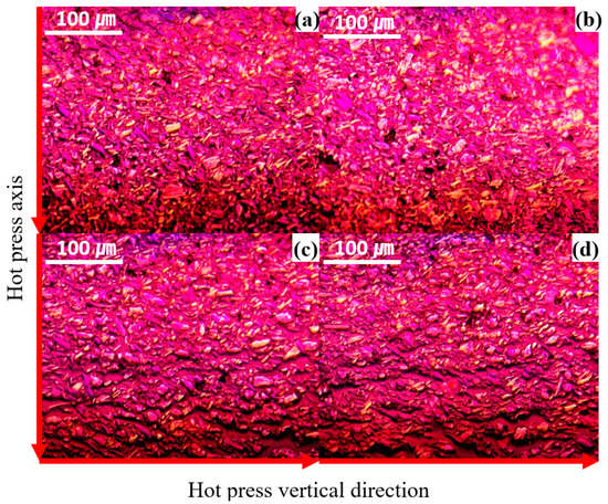
Figure 2.
Optical structure of green block: (a) B_N, (b) B_5, (c) B_10, (d) B_20.
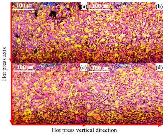
Figure 3.
Optical structure of graphite block; (a) B_N-G, (b) B_5-G, (c) B_10-G, (d) B_20-G.
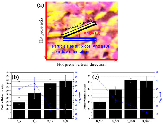
Figure 4.
Particle orientation: (a) measure method of particle orientation; (b) particle orientation of green block and (c) graphite block.
In general, for graphite blocks to have high thermal conductivity, it is advantageous that the flake-shaped needle coke particles are aligned in the direction perpendicular to the hot-press axis. To determine whether the molded structure of the manufactured graphite blocks permitted high thermal conductivity, the images in Figure 2 and Figure 3 were used to quantify the alignment structure of the needle coke particles, using the method shown in Figure 4a. The lateral size of the needle coke particles and their angle relative to the horizontal direction were measured, and then the angle was converted into cos (θ) and substituted into the following equation:
Figure 4b,c shows the particle orientation values of the green blocks and the graphite blocks, calculated using the Equation. Both Figure 4b,c indicates that, as the θ of the particles was nearer to 0°, the particles were laterally aligned in the direction that was more perpendicular to the direction of the hot-press axis. The particle orientation and θ values of the green blocks increased as the pressure increased. However, the values of the B_10 and B_20 samples were similar, showing that there was not a significant difference in the values above a certain pressure.
The particle orientation decreased in all the samples by 10.47 to 2.46% after graphitization. This may be because the low-boiling point substances in the binder pitch polymer might have expanded during the thermal treatment, forming pores or discharging externally, partially altering the orientation of the particles that were aligned during the hot-press procedure.
2.2. Physical Properties of the Carbon Molded Bodies
To verify the physical properties of the carbon molded body, the apparent density and the true density were measured and shown in Table 1. The apparent density of the green blocks increased as the molding pressure increased, but it remained at a similar value over 12.49 MPa. Before the thermal treatment, all the samples showed a similar true density, because the mixing ratio of the needle coke and binder pitch polymer was the same. In addition, even after the thermal treatment, most of the carbon molded bodies, except the B-N sample, showed similar apparent density and true density.

Table 1.
Density and porosity of the carbon molded body.
The B_N-G sample showed a porosity of 54.7 vol%; the B_5-G sample, 52.2 vol%, the B_10-G sample, 46.7 vol%; and the B_20-G sample, 38.5 vol%. As the molding pressure increased, the porosity decreased. The porosity of the graphite blocks was at a higher level, from 52.2 to 38.5 vol%, which may be because pores were formed when the low-boiling point substances of the binder pitch polymer (CV value of 47 wt%, in Figure S1) were discharged during the thermal treatment process. This result is consistent with the decrease in particle orientation found in Figure 4b,c.
2.3. Thermal Conductivity of the Carbon Molded Bodies
Figure 5 shows the thermal conductivity and porosity of the graphite blocks depending on molding pressure. The B_N-G sample showed a thermal conductivity of 12 W/mK; the B_5-G sample, 17 W/mK; the B_10-G sample, 38 W/mK; and the B_20-G sample, 42 W/mK. The thermal conductivity increased as the molding pressure increased. The comparison of porosity and thermal conductivity between the 6.24 to 12.49 MPa interval and the 12.49 to 24.98 MPa interval shows that the thermal conductivity increased by 21 W/mK in the 6.24 to 12.49 MPa interval, while it increased only by 4 W/mK in the 12.49 to 24.98 MPa interval, where the porosity was further decreased. This result was similar to the trend in particle orientation (Figure 4c) in the intervals.
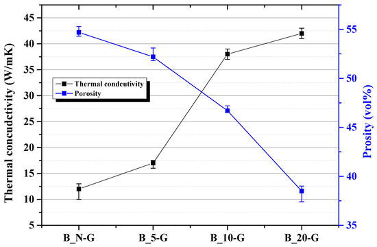
Figure 5.
Thermal conductivity and porosity of graphite block.
3. Discussion
3.1. Increase of Thermal Conductivity Depending on Orientation
Heat transfer phonons are thermally diffused by the vibration of lattices and a crystalline structure generally has an advantage in thermal conductivity compared to an amorphous structure [13,14,15]. The needle coke, the main raw material of the manufactured carbon molded bodies, has an anisotropic crystalline structure of a flow form, and thus showed high thermal conductivity in the particle direction, even after being pulverized. It was found that this phenomenon can be seen as a result of the arrangement characteristics of the particles rather than the crystallinity of the graphite block structure through XRD and Raman spectroscopy analysis (Figure S1). Figure 6 illustrates the phonon transport and scattering caused by the orientation. Figure 6a shows the inside of a well-oriented carbon molded body, indicating that rapid heat transport occurs from the hot zone to the cold zone in the direction of the particle alignment. In contrast, in Figure 6b, where the needle coke particles are randomly aligned, the heat transport by phonons occurs through complicated pathways, and thus the thermal conductivity is low [16,17,18]. Therefore, as the molding pressure was increased, the thermal conductivity increased because the needle coke particles obtained flowability in the softened binder pitch polymer during the manufacturing of the carbon molded body and thus became better oriented by higher pressure, in the direction perpendicular to the hot-press axis.
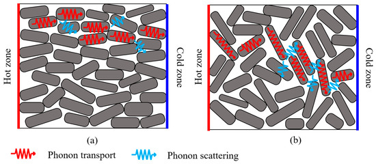
Figure 6.
Schematic diagram of phonon transport according to particle orientation: (a) high orientation; (b) low orientation.
3.2. Effect of High Porosity on Thermal Conductivity
The pores in the carbon molded body were filled with low-boiling point substances, generated by the thermal treatment of the binder pitch polymer or air that could not be discharged during the molding procedure. Air has a thermal conductivity as low as 0.025 W/mK, and the low-boiling point substances, existing in a gaseous phase, also have low thermal conductivity. Therefore, it is presumed that the phonon transport mechanism in the domains with the pores may be similar to the behavior of a polymer/filler composite. Phonons are transported along the crystalline structure of the needle coke. When phonons encounter a pore, phonon scattering, rather than phonon transport, occurs, and thus the heat transport from the hot zone to a cold zone becomes slow. Therefore, as the porosity is increased, the thermal conductivity is decreased. As a result, as shown in Figure 4c, although the particle orientation was higher in the B_10-G sample than in the B_20-G sample, the thermal conductivity was higher in the B_20-G sample, which may be because the B_10-G sample had a higher porosity than the B_20-G sample.
4. Materials and Methods
4.1. Materials
The filler used in the present study was prepared by pulverized needle coke (PMC Tech Co., Gwangyang, Korea) with a jet-mill (HANKOOK CRUSHER CO., Incheon, Korea) (pulverizing speed 6000 rpm and classifying speed 6000 rpm). Supplementary data Figure S2 shows the particle size distribution of the pulverized needle coke. The D50 particle size was 13.55 μm, and the most frequent particle size was 17 μm. The binder pitch polymer was prepared by polymerization of pyrolyzed fuel oil (PFO, LG Chem, Daesan, Korea) at 400 °C for 1 h. Table S1 shows the properties of the prepared binder pitch.
4.2. Process
The needle coke and the binder pitch polymer were kneaded using a jet-mill (pulverizing speed 6000 rpm and classifying speed 6000 rpm) at the weight ratio of 7.6:2.4. Jet-mill kneading is a high-speed rotary kneading process, where the needle coke and the binder pitch collide with each other. The physical collision generates energy, which helps coat the binder polymer onto the needle coke particle surface. Figure S3 shows SEM images of the needle coke before and after the coating, indicating that the surface of the needle coke particle became smooth after being coated with the binder pitch polymer.
To manufacture green block with the kneaded samples, molding was performed using a hot-press at 200 °C for 1 h under various pressure conditions (1.25–24.98 MPa). The green blocks were manufactured under a total of four pressure conditions: minimum pressure (less than 1.25 MPa, B_N), 6.24 MPa (5 ton, B_5), 12.49 MPa (10 ton, B_10), and 24.98 MPa (20 ton, B_20). Graphite blocks were manufactured by thermally treating the green blocks at 900 °C and then at 2800 °C. The individual graphite block samples were named by attaching ’-G’ at the end of each sample name (B_N-G, B_5-G, B_10-G, and B_20-G).
4.3. Characterization
The orientation and microstructure of the prepared pitch polymer was observed using polarized optical microscopy. Samples were embedded in epoxy resin and then polished using Struers Tegramin-25 (Struers, Cophenhagen, Denmark). The samples were observed at 50× magnification using an Olympus BX43 microscope (Olympus CO., Tokyo, Japan) [19]. Helium density and apparent density were measured to analyze the carbon molded body. The helium was measured using AccuPyc 1340 (Micromeritics, Atlanta, GA, USA), and the apparent density was measured by the Archimedes method. Porosity was measure using AutoPore IV 9500 (Micromeritics, Atlanta, GA, USA). The thermal conductivity was measured using a hot disk instrument (TPS2500S, Hot Disk Inc., Göteborg, Sweden) in a slab mode with a sensor type 5501 probe.
5. Conclusions
In the present study, the particle orientation and porosity of carbon molded bodies manufactured under various molding pressure conditions were analyzed, and the variation in thermal conductivity of the carbon molded bodies, depending on the molding pressure, was investigated. The green blocks, manufactured under a higher pressure, showed a higher particle orientation, and the graphitized blocks also showed the same result. The increased particle orientation and decreased porosity of the carbon molded bodies facilitated the phonon transport between the needle coke particles, resulting in an increase in thermal conductivity. However, in this study, the thermal conductivity was reduced by higher porosity than the particle orientation of the carbon molded bodies. The B_10-G sample, despite having a higher particle orientation value, showed lower thermal conductivity than the B_20-G sample because of the high porosity. Further studies will be conducted to develop an effective manufacturing process to increase the particle orientation of the carbon molded bodies and decrease their porosity.
Supplementary Materials
The following are available online at https://www.mdpi.com/2076-3417/10/20/7281/s1: Figure S1: XRD and Raman Spectroscopy analysis of graphite block: (a) XRD data, (b) Raman Spectroscopy data.; Figure S2: Particle size distribution of pulverized needle coke; Figure S3: SEM image of pulverized needle coke and polyaromatic hydrocarbons (PAHs, binder pitch) coated needle coke: (a) pulverized needle coke, (b) coated needle coke; Table S1: Physical properties of polyaromatic hydrocarbons (PAHs, binder pitch).
Author Contributions
Conceptualization, J.H.C., B.C.B., and J.S.I.; data curation, J.H.C. and B.C.B.; formal analysis, J.H.C.; funding acquisition, B.C.B.; investigation, J.H.C.; project administration, B.C.B.; resources, J.S.I.; supervision, B.C.B.; validation, J.S.I. and B.C.B.; visualization, J.H.C. and B.C.B.; writing–original draft, J.H.C. and B.C.B.; writing–review and editing, B.C.B.; All authors have read and agreed to the published version of the manuscript.
Funding
This work was supported by the Korea Evaluation Institute of Industrial Technology (KEIT) through the Carbon Cluster Construction project [10083621, Development of Preparation Technology in Petroleum-Based Artificial Graphite Anode funded by the Ministry of Trade, Industry, and Energy (MOTIE, Korea).
Conflicts of Interest
The authors declare no conflict of interest. The funders had no role in the design of the study; in the collection, analyses, or interpretation of data; in the writing of the manuscript, or in the decision to publish the results.
References
- Han, Z.; Fina, A. Thermal Conductivity of Carbon Nanotubes and Their Polymer Nanocomposites: A Review. Prog. Polym. Sci. 2010, 36, 914–944. [Google Scholar] [CrossRef]
- Li, M.; Zhou, Y.; Liao, Y.; Zhou, H. Effect of Defects on Thermal Conductivity of Graphene/Epoxy Nanocomposites. Carbon 2018, 130, 295–303. [Google Scholar] [CrossRef]
- Li, Q.; Guo, Y.; Li, W.; Qiu, S.; Zhu, C.; Wei, X.; Chen, M.; Liu, C.; Liao, S.; Gong, Y.; et al. Ultrahigh Thermal Conductivity of Assembled Aligned Multilayer Graphene/Epoxy Composite. Chem. Mater. 2014, 26, 4459–4465. [Google Scholar] [CrossRef]
- Tiwari, N.; Agarwal, N.; Roy, D.; Mukhopadhyay, K.; Prasad, N.E. Tailor Made Conductivities of Polymer Matrix for Thermal Management: Design and Development of Three-Dimensional Carbonaceous Nanostructures. Ind. Eng. Chem. Res. 2017, 56, 672–679. [Google Scholar] [CrossRef]
- Jin, F.L.; Li, X.; Park, S.J. Synthesis and Application of Epoxy Resins: A review. Ind. Eng. Chem. 2015, 29, 1–11. [Google Scholar] [CrossRef]
- Sato, K.; Horibe, H.; Shirai, T.; Hotta, Y.; Nakano, H.; Nagai, H. Thermally Conductive Composite Films of Hexagonal Boron Nitride and Polyimide With Affinity-Enhanced Interfaces. J. Mater. Chem. 2010, 20, 2749–2752. [Google Scholar] [CrossRef]
- Zhong, B.; Zhao, G.L.; Huang, X.X.; Liu, J.; Chai, Z.F.; Tang, X.H.; Wen, G.W.; Wu, Y. Binding Natural Graphite with Mesophase Pitch: A Promising Route to Future Carbon Blocks. Mater. Sci. Eng. 2014, 610, 250–257. [Google Scholar] [CrossRef]
- Sakai, M. Dependence of Viscoelastic Properties of a Carbon Paste on Grain Size of Coke. Carbon 1979, 17, 145–148. [Google Scholar] [CrossRef]
- Kim, J.G.; Kim, J.H.; Bai, B.C.; Choi, Y.J.; Im, J.S.; Bae, T.S.; Lee, Y.S. Influence of Kneading Ratio on the Binding Interaction of Coke Aggregates on Manufacturing a Carbon Block. Carbon Lett. 2018, 28, 24–30. [Google Scholar] [CrossRef]
- Pierson, H.O. Natural Graphite, Graphite Powders, Particles, and Compounds. Handbook of Carbon, Graphite, Diamonds and Fullerenes: Processing, Properties and Applications; William Andrew: NewYork, NY, USA, 1994; pp. 226–243. ISBN 9780815513391. [Google Scholar]
- Inagaki, M.; Kang, F. Engineering and Application of Carbon Materials. In Materials Science and Engineering of Carbon: Fundamentals; Butterworth-Heinemann: Oxford, UK, 2014; pp. 219–251. ISBN 9780128008584. [Google Scholar]
- Choi, J.E.; Ko, S.H.; Jeon, Y.P. Preparation of Petroleum Impregnating Pitches from Pyrolysis Fuel Oil Using Two-Step Heat Treatments. Carbon Lett. 2019, 29, 369–376. [Google Scholar] [CrossRef]
- Burger, N.; Laachachi, A.; Ferriol, M.; Lutz, M.; Toniazzo, V.; Ruch, D. Review of Thermal Conductivity in Composites: Mechanisms, Parameters and Theory. Prog. Polym. Sci. 2016, 61, 1–28. [Google Scholar] [CrossRef]
- Chen, Y.C.; Lee, S.C.; Liu, T.H.; Chang, C.C. Thermal Conductivity of Boron Nitride Nanoribbons: Anisotropic Effects and Boundary Scattering. Int. J. Therm. Sci. 2015, 94, 72–78. [Google Scholar] [CrossRef]
- Ye, Z.; Cao, B.; Guo, Z. High and Anisotropic Thermal Conductivity of Body-Centered Tetragonal C4 Calculated Using Molecular Dynamics. Carbon 2014, 66, 567–575. [Google Scholar] [CrossRef]
- Zhang, Y.; Rhee, K.Y.; Park, S.J. Nanodiamond Nanocluster-Decorated Graphene Oxide/Epoxy Nanocomposites with Enhanced Mechanical Behavior and Thermal Stability. Compos. Part B 2017, 114, 111–120. [Google Scholar] [CrossRef]
- Shin, H.K.; Park, M.; Kim, H.Y.; Park, S.J. Thermal Property and Latent Heat Energy Storage Behavior of Sodium Acetate Trihydrate Composites Containing Expanded Graphite and Carboxymethyl Cellulose for Phase Change Materials. Appl. Therm. Eng. 2015, 75, 978–983. [Google Scholar] [CrossRef]
- Jo, I.; Pettes, M.T.; Kim, J.; Watanabe, K.; Taniguchi, T.; Yao, Z.; Shi, L. Thermal Conductivity And Phonon Transport in Suspended Few-Layer Hexagonal Boron Nitride. Nano Lett. 2013, 13, 550–554. [Google Scholar] [CrossRef] [PubMed]
- Kim, J.H.; Kim, J.G.; Lee, C.W.; Lee, K.B.; Im, J.S. Effect of Added Mesophase Pitch During The Pitch Synthesis Reaction of PFO. Carbon Lett. 2017, 23, 48–54. [Google Scholar] [CrossRef]
Publisher’s Note: MDPI stays neutral with regard to jurisdictional claims in published maps and institutional affiliations. |
© 2020 by the authors. Licensee MDPI, Basel, Switzerland. This article is an open access article distributed under the terms and conditions of the Creative Commons Attribution (CC BY) license (http://creativecommons.org/licenses/by/4.0/).