1. Introduction
Finding the packet arrival time or frame synchronization at a receiver is an essential procedure that must be performed first for the data reception [
1,
2]. In synchronized communication networks, such as time division multiple access (TDMA) and synchronized carrier sense multiple access (CSMA) systems, a packet is transmitted at a predesignated time. Thus, the approximate arrival time of the transmission frame is known at the receiver because the transmission time is shared between the transmitter (Tx) and the receiver (Rx). Those systems are widely used in internet-of-things (IoT) communications [
3]. However, due to the clock offset between the Tx and the Rx and the propagation delay caused by the distance between them, the arrival time of the packet varies and is unknown at the Rx. Depending on the amount of clock offset and the communication distance, the packet arrival time can be defined within a certain time interval, i.e., a time window. Finding the packet arrival time at the received signal is called frame synchronization. Frame synchronization for burst communication is a well-established research field [
4,
5,
6,
7,
8,
9,
10].
To facilitate frame synchronization, the transmitter usually transmits a unique word in front of the packet (or preamble). The receiver finds the packet arrival time by detecting the received preamble. Many frame synchronization techniques by using preamble have been suggested for binary phase-shift keying (BPSK) systems [
4,
5], M-ary PSK systems [
6], continuous phase modulation (CPM) systems [
7,
8], and orthogonal frequency division multiple access (OFDM) systems [
9,
10]. Optimum frame synchronization is known as the maximum likelihood (ML) technique [
4,
8]. ML technique requires an exhaustive search among all possible packet arrival times. The huge computation is difficult to handle. Therefore, practical frame synchronization techniques have been researched so far [
4,
5,
6,
7,
8,
9,
10]. Those practical frame synchronization techniques, regardless of modulation schemes, are based on the correlation peak search. In other words, the conventional frame synchronization methods find the packet arrival time through the correlation between the received signal and the preamble. In detail, when the output of the correlator exceeds a certain threshold, the instance is determined to be the packet arrival time. The best threshold, in general, is a function of signal-to-noise ratio (SNR). Thus, to find the optimal threshold, the SNR of the received signal should be estimated before the frame synchronization. As the frame synchronization performance is highly sensitive to the SNR estimation accuracy [
11], as one of the most intuitive methods, the peak detection of the correlator output within the time window is widely used [
4]. Frame synchronization based on peak search at correlator output has a long history, but it is still the most widely used technique in recent communication systems [
6,
8,
10].
In this paper, to improve the synchronization performance of the synchronized networks, we propose a new frame synchronization method based on a convolution neural network (CNN) classifier. The CNN, one of the most famous deep learning methods, first appeared in the introduction of the LeNet-5 that recognizes handwritten numbers, and recently, it is widely used in the field of image processing [
12,
13,
14,
15,
16] and wireless signal processing [
17,
18]. Herein, we propose a new frame synchronization method by transforming the frame synchronization problem into a CNN problem. To the best of our knowledge, there is no existing work that applies CNN-based techniques to the frame synchronization problem. Specifically, the one-dimensional (1D) correlator output for frame synchronization is transformed to a two-dimensional (2D) signal, and the 2D signals are used as the training samples with the ground truth labels, which are obtained in the training signal generation. As CNN is specialized in image processing, converting the original 1D signal into 2D signal is a widely used technique to apply CNN in other applications. The training samples are generated under additive white Gaussian noise (AWGN) channels with random arrival times and SNRs. Those 2D signals are inputted to the CNN, and the CNN classifier is trained to predict the packet arrival time. We design the CNN classifier with three convolutional layers and one fully connected layer. The proposed technique does not require any prior information except the correlator output. We examine the false detection probability (FDP) of the proposed CNN-based and the convolutional correlation-based methods through computer simulation. Without retraining the CNN, the FDP performances are evaluated under AWGN and fading channels. According to the results, it is verified that the proposed CNN-based technique outperforms the conventional method by
in both AWGN and fading channels. The main contribution of this study is summarized as follows.
CNN-based techniques to the frame synchronization problem.
1D correlator output is transformed to a 2D signals for better training of the designed CNN.
The designed CNN is evaluated under various channel environments, namely, AWGN and fading channels.
The proposed CNN-based method improves approximately SNR for the frame synchronization.
2. System Model
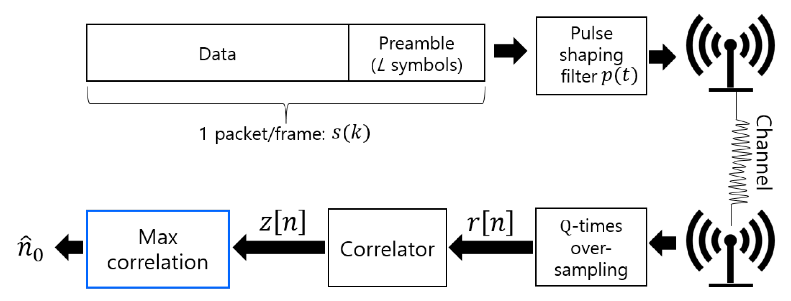
In this study, we consider a synchronized communication network, in which a Tx transmits signals to an Rx at predesignated time
. The Tx packet consists of the preamble and data in the front and end of the packet, respectively, as shown in
Figure 1. In this scenario, the Tx transmits a packet at
, yet the packet arrival time has some deviation due to clock offset and propagation delay between the Tx and the Rx. As the time deviation is bounded within a certain time window with size
W by designing the system depending on the amount of clock offset and the distance, we can assume that the packet arrival time falls within the time window
. The preamble consists of the BPSK modulated signals and its length is denoted by
L. Here, we note that any modulation scheme is applicable to the proposed technique, which will be introduced shortly.
Figure 1 shows the overall block diagram of frame synchronization. It is assumed that the received signal is Q-times oversampled compared to the transmitted symbol rate. The received analog signal and its sampled digital signal, respectively, can be represented as
where
T is the symbol duration,
is the Tx symbol (first
L symbols are the preamble),
is the impulse response of the pulse shaping filter,
is white Gaussian noise, and
is the packet arrival time that should be found at the Rx. In conventional frame synchronizers,
is found via the correlation between the preamble
and the received signal
. As the sampling frequency of the received signals is
Q-times higher than that of
, the correlation in the correlator in
Figure 1 can be obtained as
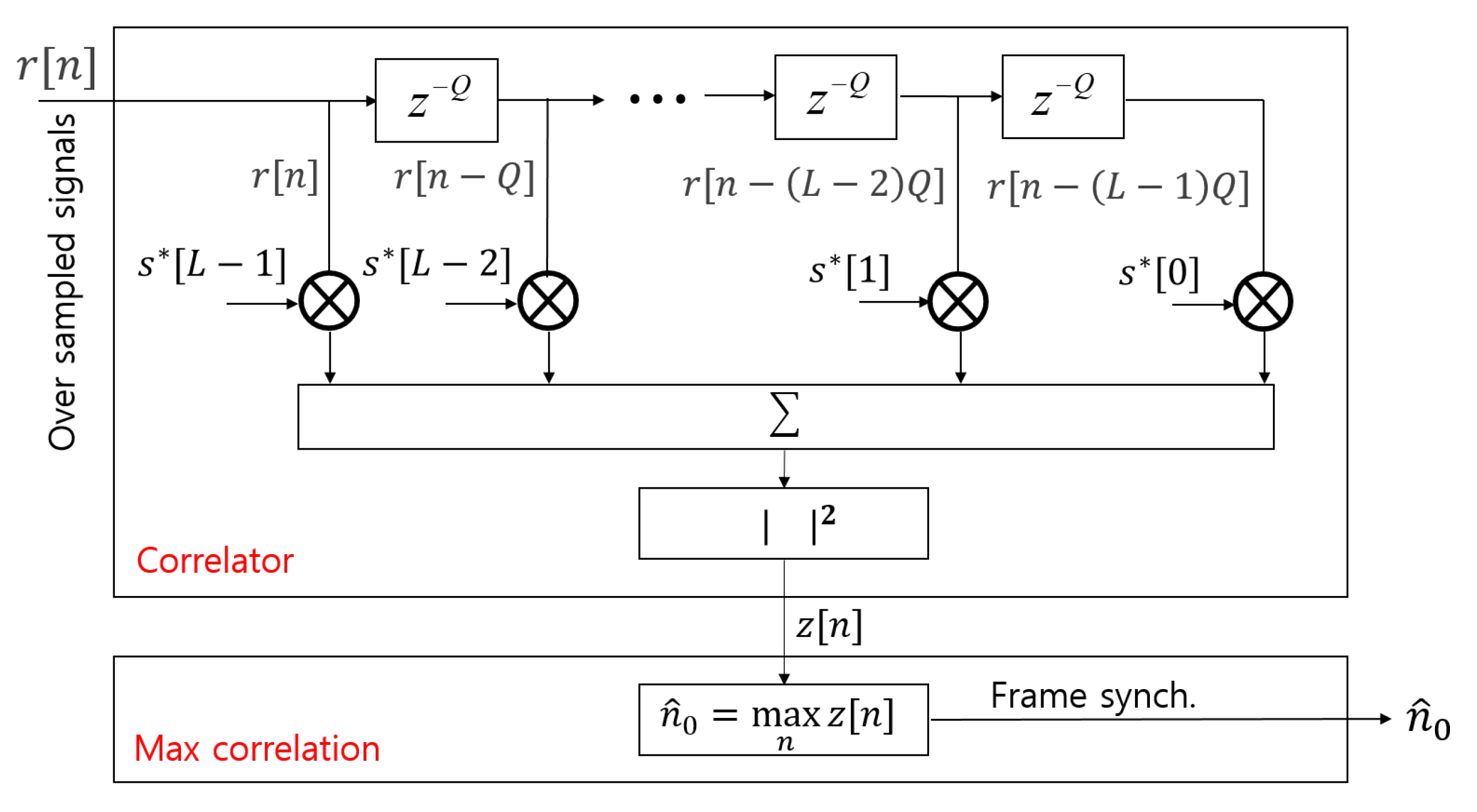
and thus, the structure of the correlator is as shown in
Figure 2.
As the sampling frequency is , the packet arrival time corresponds to in the correlator output, where denotes a ceiling operation. Therefore, is the starting point of the packet and it should be found at the Rx.
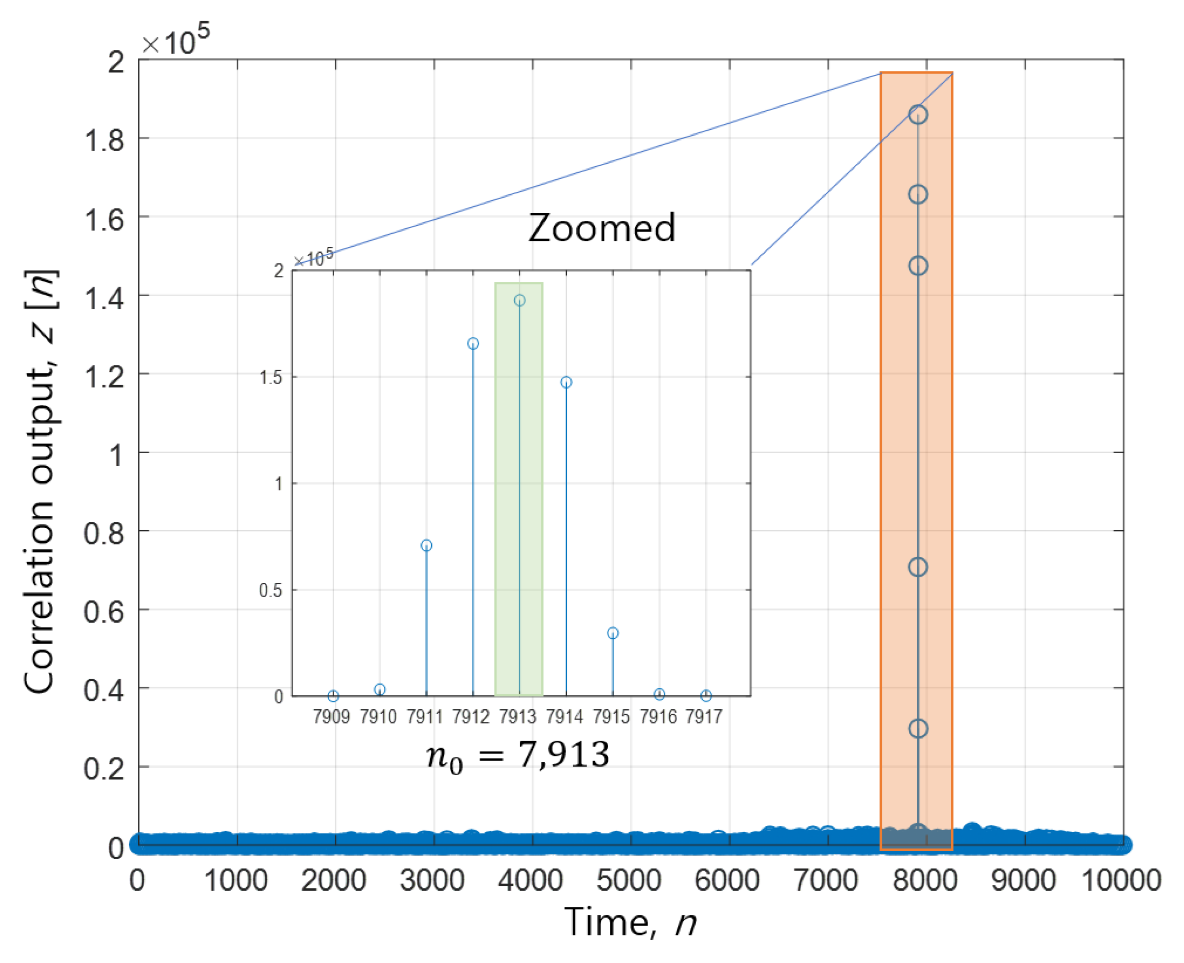
Figure 3 shows an example of the correlator output, where the window size is 10,000, i.e.,
. The maximum of the correlator output occurs at
, i.e.,
. If
exists within the time window, searching the maximum value of the correlator output
within the window will be one of the best policies and it is described as follows,
In this synchronized network case, it is advantageous that frame synchronization can be performed without SNR estimation. Throughout this paper, this correlation-based method is called a conventional method.
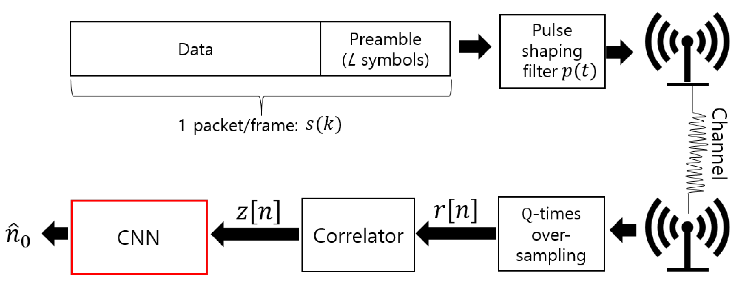
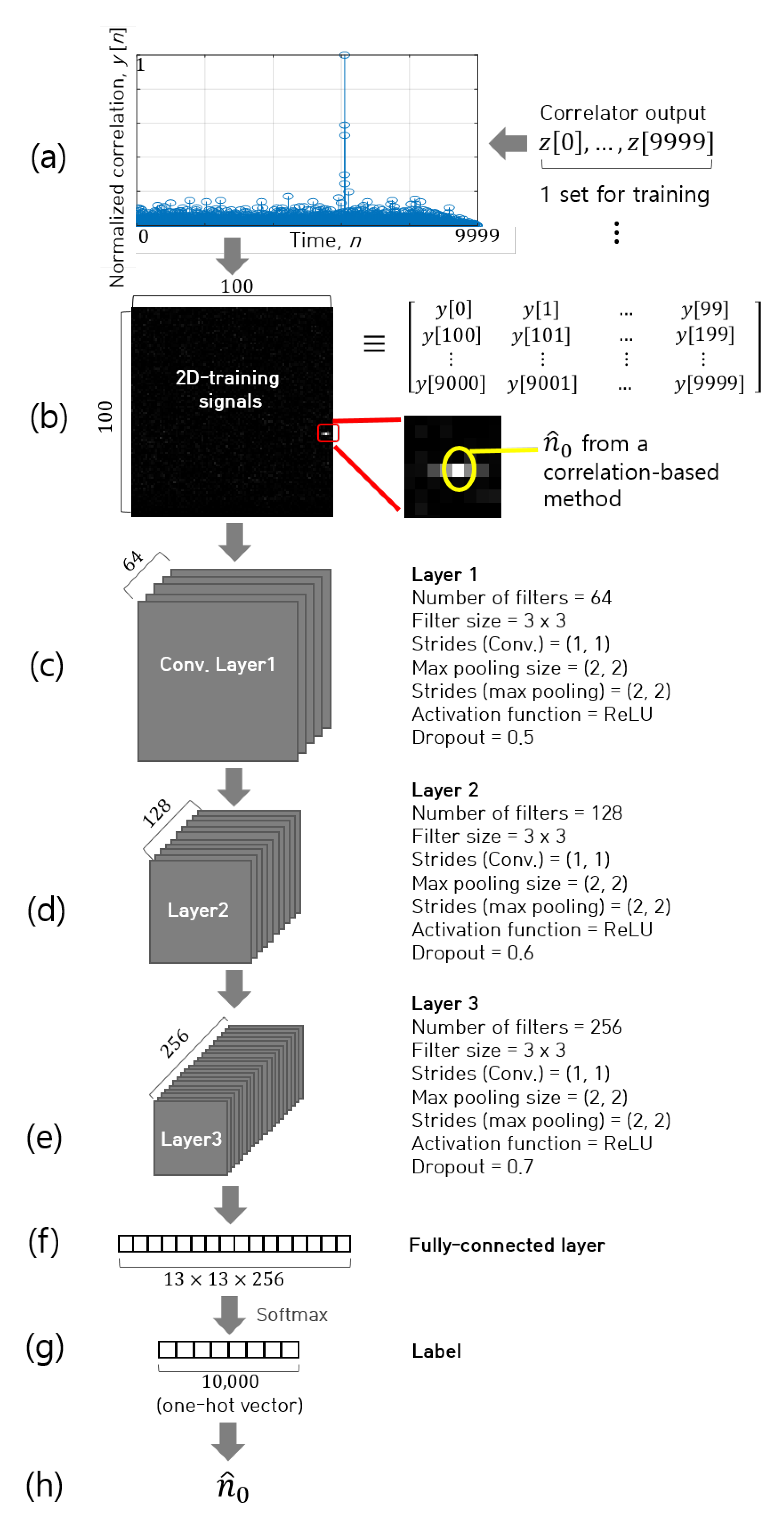
3. Proposed CNN-Based Frame Synchronizer
In this section, we propose a new synchronization method using a CNN classifier as shown in
Figure 4. The CNN classifier generates the estimated arrival time, i.e.,
, from the input signals that is the correlator output signals,
in (
3). The detailed procedure of the proposed CNN classifier is depicted in
Figure 5, and the specific parameters for it are summarized in
Table 1. For a simple description of the proposed method, we set the window size by
, i.e.,
. Note that the proposed method can be applied to an arbitrary size of time window by slightly modifying the CNN structure.
The first step is a training sample normalization step as shown in
Figure 5a, in which the correlator output signal,
, is normalized such that its maximum value is one as follows,
Next, the
1D signals are converted to
2D training signals by performing matricization operation with a row-major order and its dimension is
. Precisely, as shown in
Figure 5b, the first 100 samples become the first row, the next 100 samples become the second row, and so forth. The converted 2D-training signals can be represented by a black and white (monochrome) image as depicted in
Figure 5b, in which the bright and dark colors indicate large and small values of
, respectively. Thus, we can interpret that the lightest part of the image implies a packet arrival instance of the conventional correlation-based synchronization method. Here, we have to note that the estimated arrival time
from the designed CNN could be different from
obtained from the maximum correlation-based method. This will be shown in the next section.
The 2D-training signals are then provided to the designed CNN classifier. The structure of the proposed CNN regressor is shown in
Figure 5c–g. The input is
2D-training signal and it passes through three convolutional layers (panels (c–e)) and one fully connected layer (panel (f)). The final output in panel (g) is
one-hot vector and “1” indicates the packet arrival instance. The convolutional filter size is
, and the number of filters (or channels) at each of the three convolutional layers is 64, 128, and 256, respectively. Using the sufficient number of training signals and their labels, the CNN parameters are updated to minimize the difference the CNN regressor output and the label. In a label vector, only one element has a value of one and the others have zeros, where the position of element 1 indicates the packet arrival time, i.e.,
in (h), which is the output of the CNN block.
4. Simulation Results
The performance of the proposed frame synchronizer is examined through computer simulation. Two preamble lengths ( and ) are considered. The preambles are pseudo-random sequences. Usually, the longer preamble results in better frame synchronization performance. For the training the proposed CNN, a total of sets of the received signal are generated. The SNR of each training set is randomly selected between and , and the packet arrival time is also randomly selected in the time window from 0 to 9999, i.e., . The learning rate is and an optimization algorithm is an adaptive moment estimation (ADAM). The proposed CNN is learned for 80 epochs, i.e., training signals are reused 80 times. After successful training, the proposed CNN can find the any packet arrival time in the range of 0 to 9999; therefore, the additional training does not required for different transmission delays. For frame synchronization performance evaluation, test signals are generated under AWGN channel environments with , and at each SNR, test signals are generated with random packet arrival times. As the performance evaluation signals are generated independently with the training signals, the two sets of data do not overlap.
The CNN training and performance evaluation are performed by using
MATLAB 2020a. To use useful functions on deep learning, a
Deep Learning Toolbox is also required. To accelerate training speed, a graphic process unit (GPU) GTX1080Ti with compute unified device architecture (CUDA)
is used. To training the CNN, a
trainNetwork function is used. The input of
trainNetwork is training input signals, designed neural network, and optimization parameters. The output of
trainNetwork is the trained parameters of CNN. For performance evaluation of the trained CNN, a
predict function is used. The input of the
predict function is the trained CNN parameters and the input signals for the performance test.
Table 2 summarizes the simulation software environments.
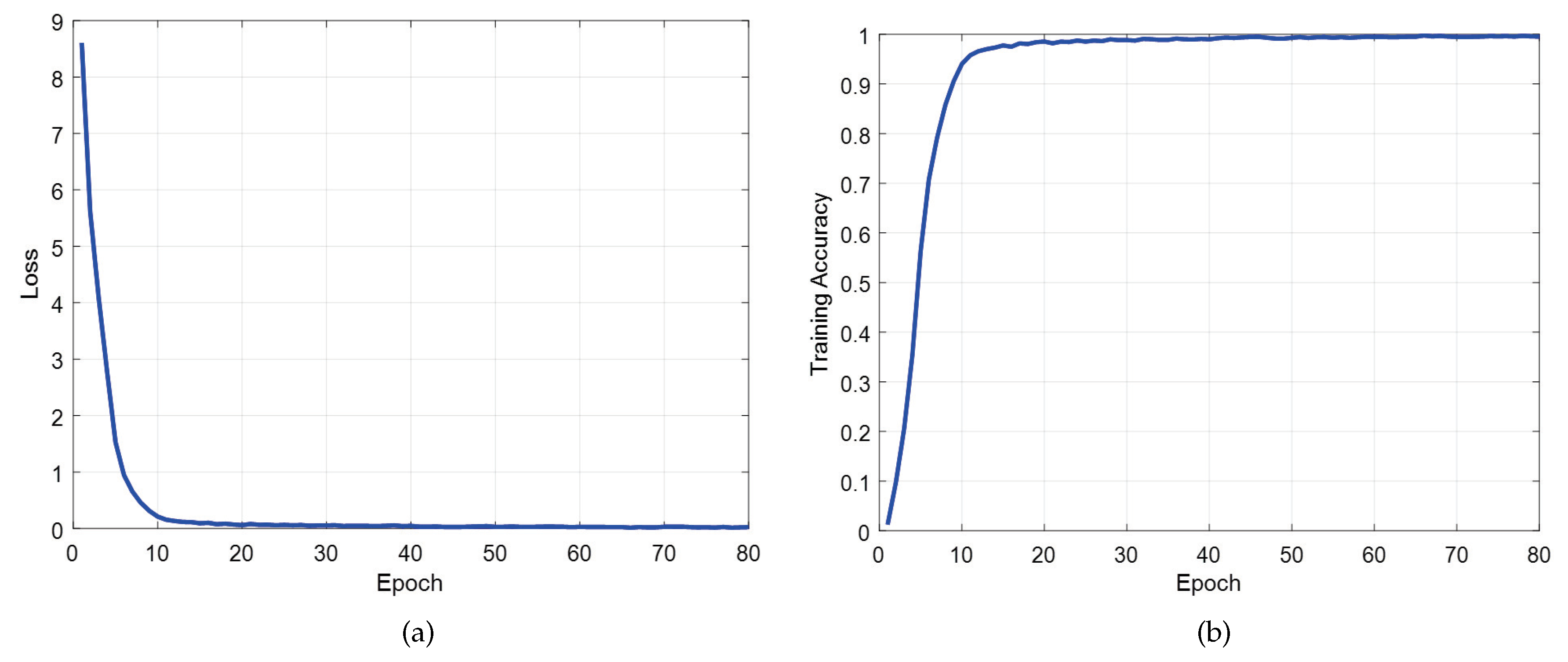
The learning curves of the proposed CNN were shown across the number of epochs for the loss and training accuracy in
Figure 6a,b, respectively. To train the CNN, the cross entropy is used for the loss function, defined as
where
is packet arrival time,
is the softmax output in
Figure 5, and
is the ideal probability, i.e.,
The loss in
Figure 6a represents
V in (
6), and the accuracy in
Figure 6b is the ratio of the correctly estimated cases among total
training signals. From the results, it was evidently shown that the proposed CNN accurately converges at approximately 50 epochs.
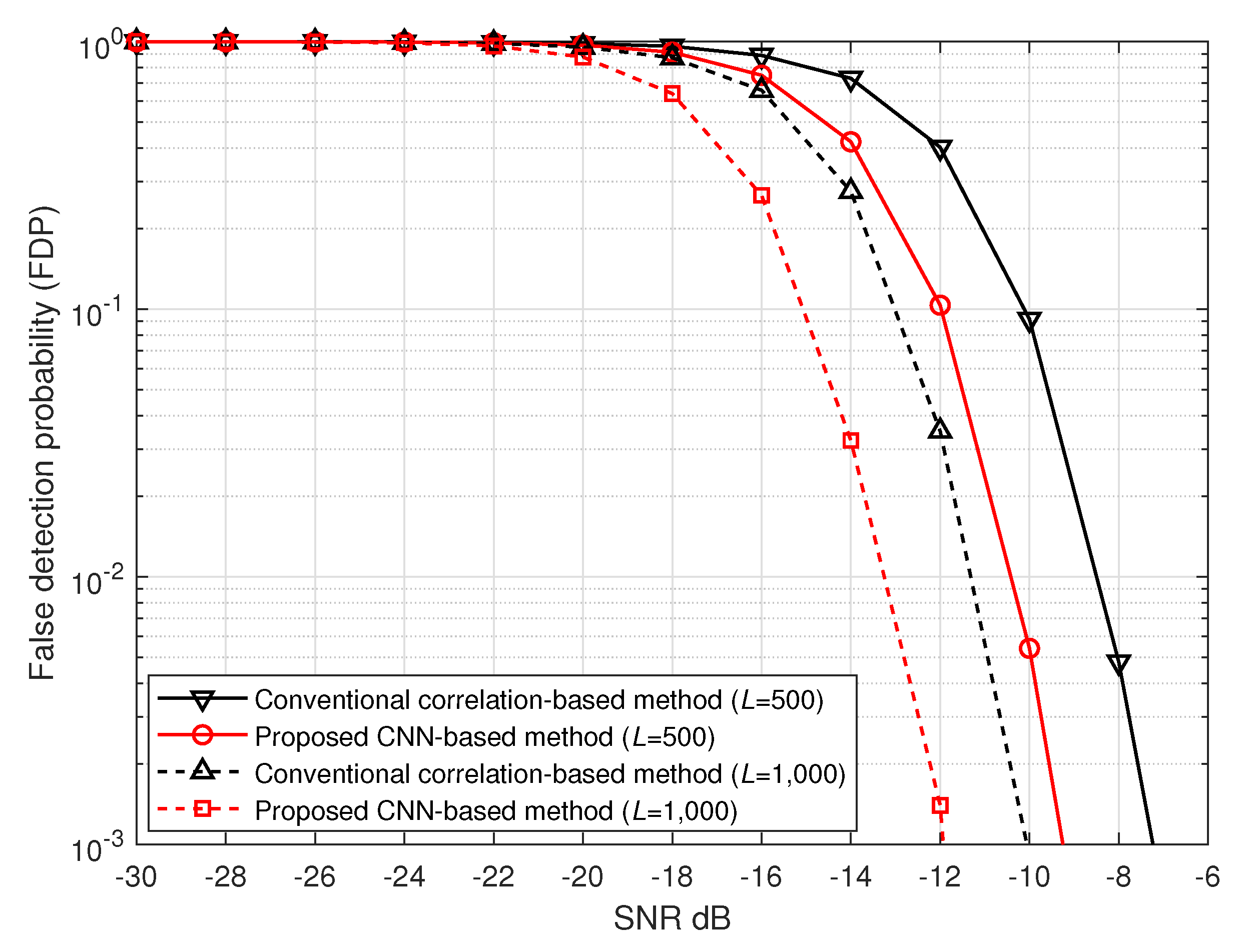
Figure 7 shows the FDPs of the proposed CNN-based and the conventional correlation-based synchronization methods [
6,
8,
10] in AWGN channels. From the results, we observe that the proposed CNN-based technique outperforms the conventional correlation-based method regardless of the preamble length, and a longer preamble provides better FDP. Concretely, the proposed method shows
gain over the conventional method, regardless of the preamble length, and the preambles with length 1000 achieve
better than that with length 500.
Figure 8 shows the FDPs for flat fading channels with
. During performance evaluation in fading channels, the CNN is not retrained. The same CNN trained with signals under AWGN environments is used and the performance evaluation signals are newly generated. To generate received signals in
fading channels, the following model is used,
where
c is the fading coefficient which is Gaussian random variable with variance one. This channel model is suitable for non-line-of-sight terrestrial communication systems. This simulation is performed to confirm whether the proposed technique works well for the received signals different from the training situation. According to the results, the proposed method still
better than the conventional method. Those results indicate that the proposed CNN operates very flexibly in various channel environments. By improving the frame synchronization performance by
, the transmitter can reduce the transmit power to increase the battery lifetime, or extend a communication range farther.
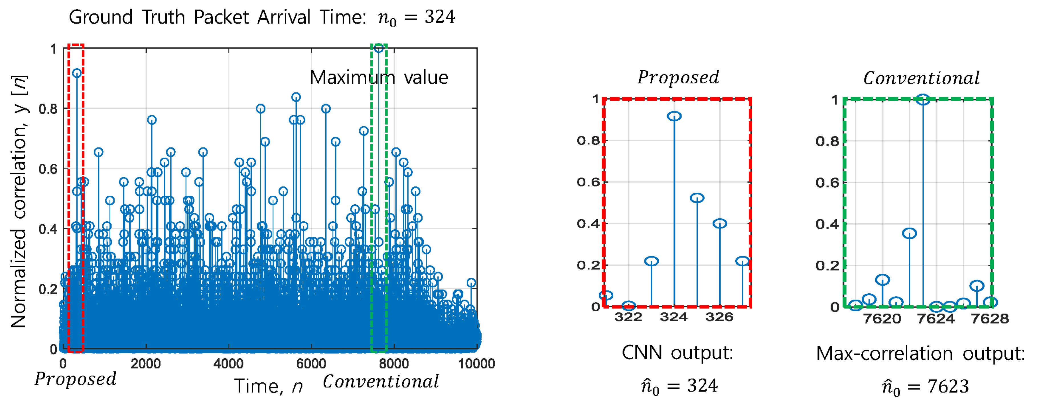
To investigate the rationale of why the proposed CNN-based technique outperforms the conventional correlation-based method, we show one snapshot
Figure 9 of the correlator output for the case when the correlation-based technique finds the wrong packet arrival time, while the CNN-based method finds it correctly. The ideal correlator output conforms to the normal distribution with a mean value around the packet arrival time due to oversampling effects. The conventional correlation-based frame synchronization method finds just the maximum position ignoring the shape of the distribution of
. However, we can conjecture that the proposed CNN-based frame synchronization method finds the packet arrival time by considering not only the scale but also the shape of the correlation values.


