1. Introduction
Thermoplastic composites (TPC) have an important contribution to modern lightweight construction due to their excellent density-related mechanical properties and established efficient production processes [
1]. However, one of the obstacles for the use of TPC in multi-material systems is the availability of suitable joining technologies. To increase the efficiency and reduce the complexity, automobile manufactures intend to keep the number of different joining technologies as low as possible [
2]. Resistance spot welding is a standardized joining technology, which is widely used for sheet metal structures [
2]. Nevertheless, the use of resistance spot welding for multi-material joints is not directly possible due to different physical properties of dissimilar materials, such as melting temperatures and micro-structural incompatibilities [
3]. For this reason, various studies address research regarding the welding of dissimilar materials, such as composites or aluminium to steel. The objective is to use conventional spot-welding guns in established metal-oriented processes for composites as well. One approach is to integrate additional metallic elements as joining interfaces. The usage of an auxiliary joining element allows to avoid the welding incompatibility of dissimilar materials [
4]. These elements can be integrated into composites during or after the part manufacturing process. Joesbury et al. [
5] presented a process for thermoset matrix composites based on the integration of a metallic intermediate plate in the joining zone prior to the infiltration process. Subsequently, the weld was created, and finally, the whole assembly was infused with resin. Roth et al. applied a flat weld insert into the composite during preforming, whereby the fibres were displaced by a pin in the welding area [
6]. Subsequently, the component was infiltrated in a resin transfer moulding (RTM) process, excluding the welding zone.
An example for the application of additional metallic elements after the composite part manufacturing process is described by Shah et al. [
7]. The composite joining part was pre-punched in the flange area and then additional steel doubler strips were positioned on the composite and bonded with adhesive. In the hole area, the additional steel doubler strips were then welded to the metal component creating a form fit between composite and steel. Other studies have investigated the principle of resistance element welding, which was developed for joining high-strength (e.g., ultrahigh-strength steel) and low-ductile materials (e.g., aluminium) in multi-material joints [
8]. The additional steel element can be positioned in a pre-hole [
9] of the composite component or directly inserted by a punching process and joined to the steel component by resistance welding [
10]. Weykenat et al. presented an approach to insert multiple metal layers (multilayer insert) locally into a composite using automated fibre placement [
11]. These multilayer inserts lead to a reinforcement of the hole, into which a Flexweld
® insert was inserted to join the composite to a steel component by resistance welding [
12].
These joining techniques allow the use of conventional spot-welding guns and the integration of composite components in production lines established for metals. Besides, they cause local damage to the reinforcing fibres, which results in reduced load bearing capacity as shown for moulded holes compared to drilled ones [
13]. For this reason, Obruch et al. [
14] developed a new type of weld insert with a head plate and pins, which is suitable for low-damage integration into thermoplastic composites. Despite the reduction of fibre damage, as no pre-hole is necessary, it has the disadvantage that the embedding of the weld insert is an additional process step. Therefore, the authors pursue a new approach, in which the weld insert is integrated during composite component manufacture in the compression mould without fibre damage.
2. Materials and Methods
2.1. Process-Integrated Embedding of Weld Inserts into TPC
The technology of process-integrated embedding of weld inserts into TPC uses the principle of moulding holes by a pin tool and simultaneously places weld inserts in the moulded hole [
15]. Thereby, the reinforcing fibres are not cut by punching or drilling but shifted aside by a tapered pin tool while the TPC is hot and formable [
16]. The integration of the embedding process of the weld inserts into the composite component manufacturing process provides the possibility of reducing the number of process steps and manufacturing costs.
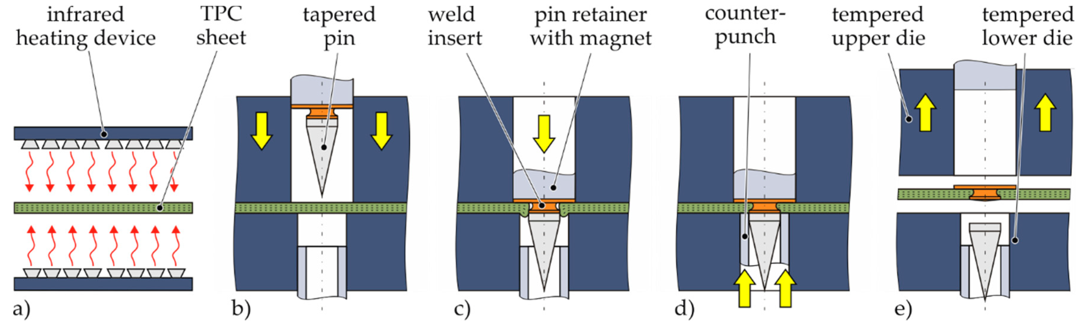
The process is schematically illustrated in
Figure 1. At first, a pre-consolidated TPC sheet is warmed up above melting temperature of the matrix polymer by an infrared heating device (
Figure 1a). Subsequently, the TPC sheet is transferred into the open compression mould. Immediately after mould closing (
Figure 1b), a pin tool is shifted forward, forming a hole by displacing the reinforcing fibres and the still molten thermoplastic matrix (
Figure 1c). The pin tool consist of a pin retainer containing a magnet to fix the steel weld insert and the tapered pin. After the pin movement, a ring shaped counterpunch recompresses the squeezed-out material whereby the undercut of the weld insert is filled with fibres and matrix material (
Figure 1d). The embedding of the weld insert (steps c and d) takes less than one second. After cooling and solidification of the TPC specimen, the pin retainer is retracted and the tapered pin is separated. Finally, the TPC specimen with integrated weld insert is demoulded (
Figure 1e).
The process parameters for the embedding of weld inserts in TPC were identified based on the experience of moulding holes [
17] and process-integrated embedding of metal inserts into TPC [
16]. A tempered steel mould (in this case 40 °C, cf.
Table 1) on laboratory scale with vertical flash face is applied to produce plane test specimens with embedded weld inserts. The pin tool is pneumatically actuated, such as the counterpunch. The feed forces have been set at approximately 2.5 kN and 5 kN, respectively (cf.
Table 1). A schematic illustration of the temperature curve during process-integrated embedding of weld inserts in TPC with the heating temperature of the TPC set to 210 °C and photos of TPC test specimens with integrated weld inserts are shown in
Figure 2.
2.2. Material Specification and Geometry of the Weld Inserts
The relevant investigations were performed on TPC sheets made of unidirectional glass fibre reinforced polypropylene (GF/PP) tapes, which were produced in an autoclave. GF/PP is a typical material for TPC applications with moderate thermal and mechanical requirements. For example, it is used for the large-series production of thermoplastic door module carriers [
18]. A low-alloyed steel with high yield strength and a good weldability was chosen for the steel sheet as a typical representative of reinforcement parts e.g., in the automotive industry [
19]. A high availability and good weldability are the requirements for the weld insert. An unalloyed structural steel was selected for this purpose. The properties of the TPC as well as the metal sheets and weld inserts used are shown in
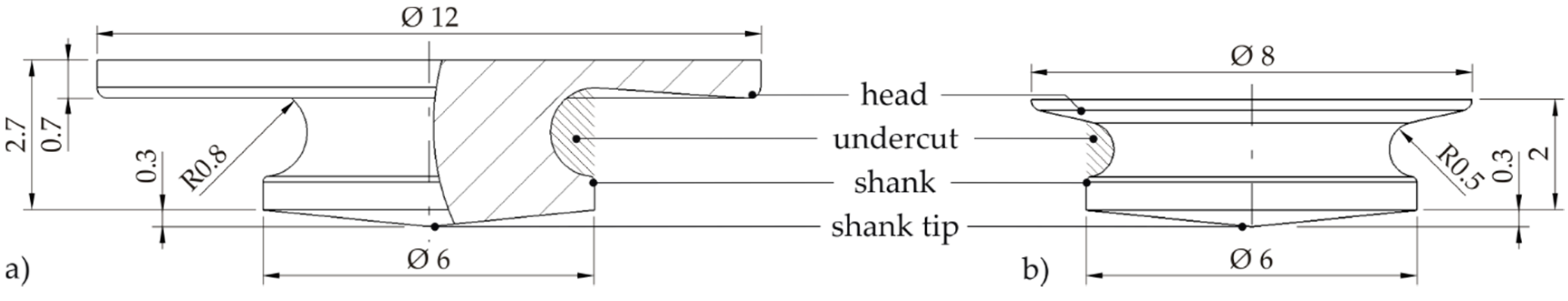
Table 2. Two different types of weld inserts were embedded in TPC specimens, both rotationally symmetric, see
Figure 3. Type A has a head geometry that protrudes from the composite surface as a disturbing contour, whereas type B has a countersunk head and therefore is flush with the composite surface. Both weld inserts have similar shank tips, in order to ensure that the volumes in the welding area are comparable during the welding process.
2.3. Resistance Element Welding (REW)
After embedding the weld inserts in TPC, experimental investigations regarding resistance element welding were conducted using a powerGUN 2-C type C-frame welding gun by NIMAK International GmbH (Wissen, Germany). This welding gun has a servomotor drive with a projection of 700 mm and a maximum electrode force of 8.0 kN. The medium-frequency direct current welding device is equipped with a welding case of the type SK-Genius HWI436WA by Harms & Wende GmbH & Co. KG (Hamburg, Germany), which has a constant current control and provides a maximum weld current of 65 kA. Standardised Electrode caps of type ISO 5821-A0-20-20-100 made from CuCrZr material were used.
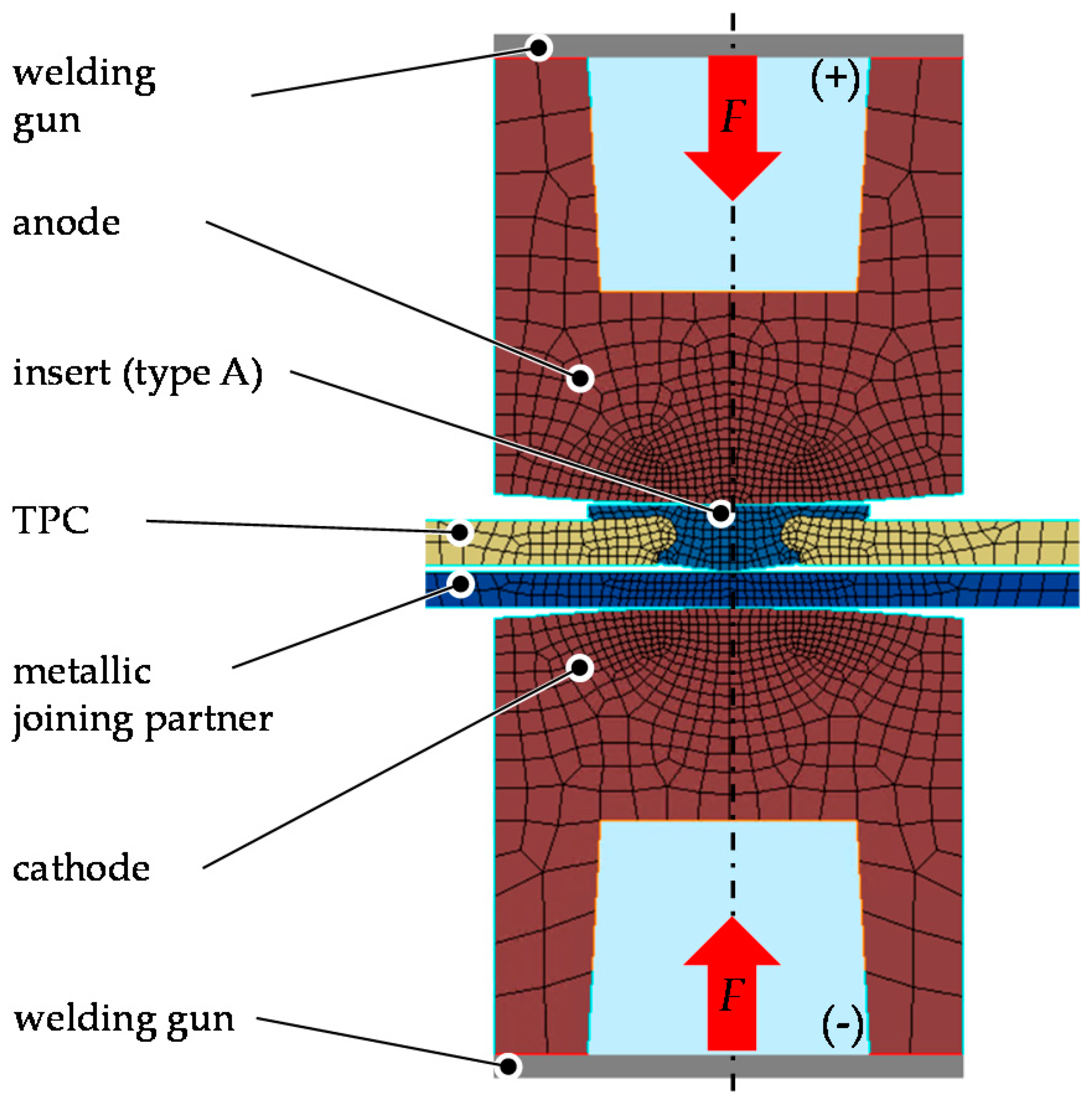
The identification of welding areas and the selection of process reliable welding parameters for the qualification of the developed weld inserts were carried out using the numeric simulation software SORPAS
® 2D Welding V13.83 Enterprise Edition by SWANTEC Software and Engineering ApS (Kongens Lyngby, Denmark, 2020). In this study the welded joint is created between the isotropic metallic weld insert and a steel sheet. In this regard a two-dimensional, axisymmetric simulation model was built, as shown in
Figure 4. The model was built according to the experimental setup. The thermal and the electrical properties of the metallic joining partners and the electrode caps were taken from the SORPAS database. The TPC was modelled in a simplified form as a thermal isotropic material. The electrical resistivity
and the thermal conductivity
of the TPC were adjusted according to the data sheet values. All parts were modelled as deformable bodies with heat conduction. For the mesh, quadrilateral elements (954 elements; 1108 nodes) were used. The associated results are presented in Chapter 3.2.
2.4. Mechanical Testing
Both prototypic weld inserts have a shank with an undercut to prevent the weld insert from falling out when handling the composite component before joining by REW. Push-out tests were carried out on TPC specimens with embedded weld inserts before welding in order to investigate whether the handling strength is guaranteed. For this purpose, the weld inserts were loaded against the embedding direction. The push-out tests were performed on a universal testing machine (see
Figure 5a). The size of the TPC test specimens was 100 × 100 mm
2 and the weld inserts were positioned in the centre. The test specimens were clamped between steel plates with a clearance hole diameter of 18 mm. The load was applied to the weld insert by a pressure pin at a constant crosshead velocity of 1 mm/min.
After welding the TPC sheets to steel sheets, the welded joints were investigated by chisel tests in accordance with [
21] to verify the chosen welding parameters. Chisel test as well as microsections were conducted on quadratic specimen (45 × 45 mm
2) with the weld inserts placed in the centre. Joint strength tests of welded TPC-steel-joints were conducted on single-lap shear specimen in accordance with [
22] at quasi-static load. Before welding, the TPC specimen with embedded weld inserts were cut from size 160 × 100 mm
2 to 115 × 45 mm
2. The geometry of the specimen is shown in
Figure 5b. The tests were performed on a high-rigid universal testing machine (Zwick Z100, by ZwickRoell AG, Ulm, Germany) at a testing velocity of 10 mm/min. The displacement was measured locally in the area of the joint using long-stroke extensometers. The extensometers were positioned each at a distance of 22 mm from the joint centre. The tests ended in the complete separation of the specimen.
3. Results
3.1. Process-Integrated Embedding of Weld Inserts in TPC
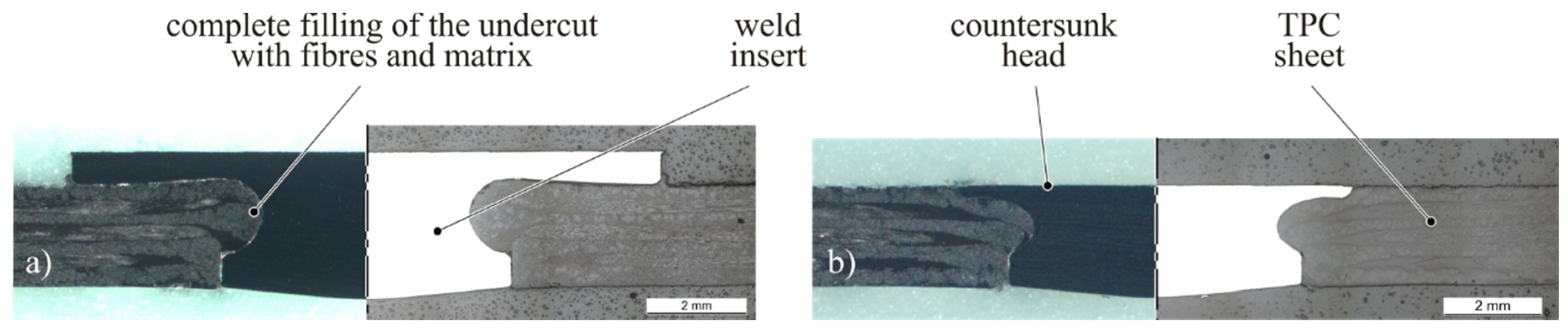
Microscopic examinations of cross sections before REW were carried out to evaluate whether the selected process parameters are suitable for manufacturing high-quality joining zones. As is evident from
Figure 6, a complete filling of the undercut with reinforcing fibres and matrix can be achieved for both types of weld inserts. In addition, it is evident that the weld inserts are well positioned with the shank tip protruding from the laminate, thus enabling the welding process. Thus, the selection of the process parameters could be confirmed as suitable for further investigations.
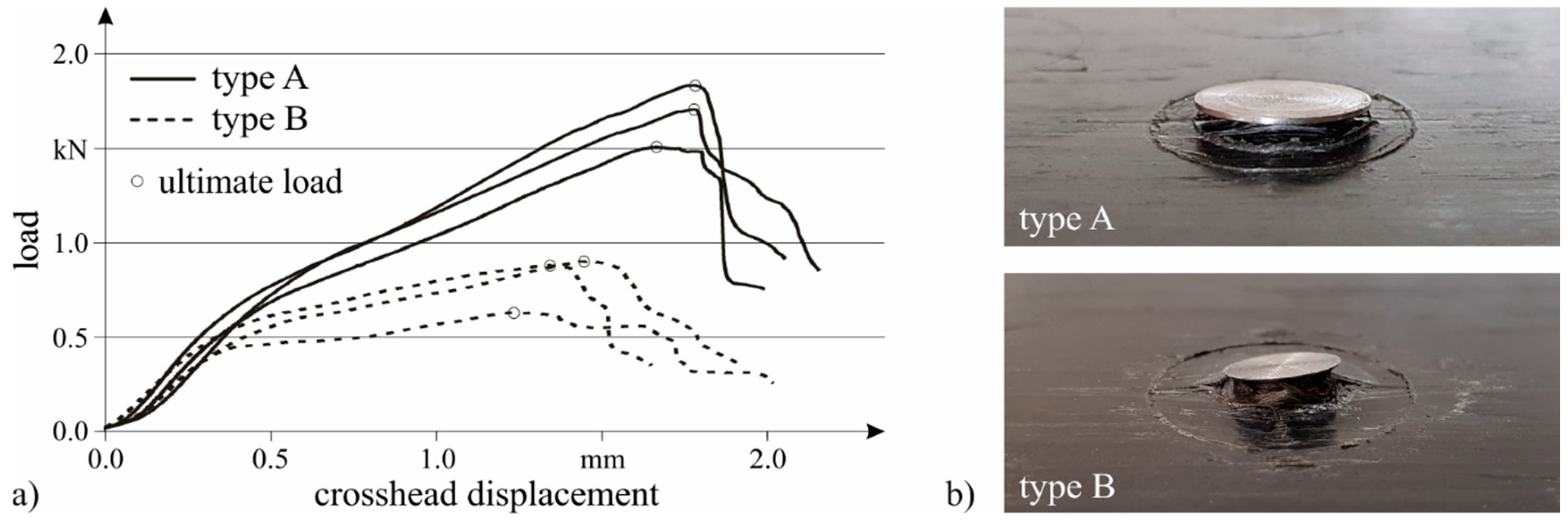
After qualifying the embedding process by means of microscopic examinations, push-out tests were performed on weld inserts embedded with the selected parameters before REW. The findings are summarised in
Figure 7. All load-displacement curves show a progressive initial increase, then an almost linear section before the gradient of the curve declines. From then on, the load increases almost linear up to the maximum push-out force (cf.
Figure 7a). The achievable maximum push-out force depends on the weld insert’s geometry. In [
16] it was demonstrated that the undercut volume has significant influence on the achievable out-of-plane loads for embedded inserts. Weld insert type A has an undercut volume of 16.8 mm
3 compared to 6.9 mm
3 of type B (cf.
Figure 3). Due to the larger undercut, type A with 1.7 kN (arithmetic mean) reaches a higher ultimate push-out load than type B with 0.8 kN (arithmetic mean). For both types of weld inserts, the push-out loads are considered high enough for the further handling process.
3.2. Welding Process Simulation
After qualifying the embedding of weld inserts in TPC, the aim was to determine suitable welding parameters for resistance element welding of the TPC-steel-joints. To ensure a resource-efficient determination of welding areas and reliable welding parameters for the joints, numeric parameter studies were carried out prior the experimental investigations. In order to validate the numeric simulation model, the results of a process simulation were compared to the results of corresponding experimentally welded joints with respect to both the geometry (height and diameter) of the weld nugget and the shape of the heat-affected zone.
Böddeker et al. [
23] have reported that for REW of a TPC-steel combination acceptable joints can be provided using electrode caps of the type ISO 58211-A0-20-16-100 and an axial electrode force of 3.0 kN. For this reason, similar boundary conditions were selected for this study. For the validation of the simulation model, a weld current of 9.0 kA and a weld time of 60 ms were chosen. The geometric comparison of the experimental and simulative results as well as the evaluation of the weld nuggets are shown in
Figure 8.
By comparing the geometry of the welded area and the heat-affected zone, it can be seen that the process simulation has a good correlation with the experiment. The deviations of the nugget diameter and the nugget height are less than 10%. Therefore, it can be stated that the simulation model ensures a satisfying agreement with the experiments. It can be seen in
Figure 8a that the chosen welding parameters lead to a slight deformation of the weld insert in the undercut area. A reason for this phenomena may be a too high thermal energy input during the welding process, which causes a softening of the material in the area of the undercut, where the cross sectional area is minimal. Due to the reduced cross-sectional area, the yield strength of the material is exceeded as a result of the contact pressure of the electrodes, causing the deformation of the weld insert. The thermal energy induced in the weld insert depends on several factors, such as the geometry of the insert, the weld time and weld current, or the electrode force, which has an influence on the contact resistance.
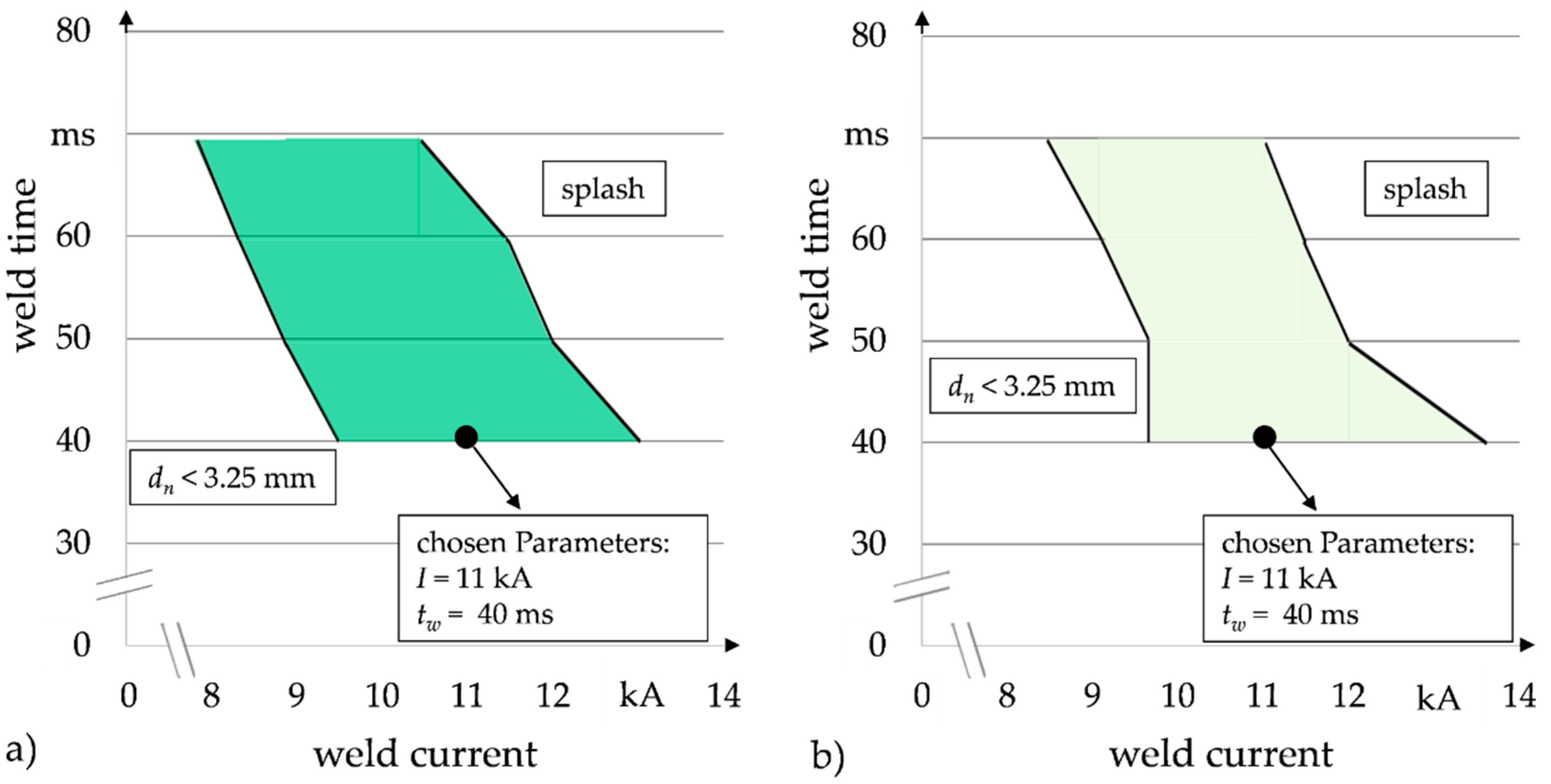
Afterwards, using the optimisation tool available in SORPAS, weld growth curves were generated for discrete weld times in order to define suitable weld current ranges in which appropriate joints can be generated. For this purpose, the weld current (
I) was increased in 0.5 kA steps for a given axial electrode force of 3.0 kN. Weld times (
tw) were increased in 10 ms steps in between 40 ms and 70 ms. For the welding areas, a nugget diameter (
dn) of 3.25 mm was defined as the lower limit and the occurrence of splashes as the upper limit.
Figure 9 shows the weldability lobes for weld insert types A and B determined by this approach.
According to the results determined by numeric simulation, weldability lobes extending over a range of approximately 2.5 kA (type A) to 3.5 kA (type B) can be expected. With the decreasing weld time, higher currents are required to produce sufficient weld nuggets. At the same time, an extension of the weldability lobes following a reduction of the weld time can be observed, which is consistent with the investigations from [
23]. Based on the determined weldability lobes, suitable welding parameters were selected for the subsequent mechanical tests. As Roth et al. [
24] showed that for REW short welding times at higher welding currents result in a lower heat input and, consequently, lead to a significantly smaller heat-affected zone, a short weld time is expected to minimise the deformation of the weld insert compared to
Figure 8 and the thermal impact of the thermoplastic matrix of the TPC. Furthermore, high weld times [
23], as well as too high weld currents [
25] may lead to thermal damage of resistance element welded polymer-steel-joints. Therefore, a weld time of 40 ms and a weld current of 11 kA was selected for both types of weld inserts, as this current is located centrally in the determined weldability lobes, thus, ensuring a high level of process reliability.
3.3. Mechanical Testing of Welded Joints
The verification of the selected welding parameters determined by numeric simulation was carried out based on etched microsections for both weld insert types. In addition, chisel tests were conducted, in order to verify a sufficient strength of the weld nugget. In
Figure 10, the mentioned microsections and photographs of samples after the chisel tests are shown.
For the weld nuggets, diameters of 3.9 mm (type A) and 4.4 mm (type B) as well as heights of 1.2 mm (type A) and 1.3 mm (type B) were determined. The diameters of the weld nuggets as well as the shape of the heat affected zone are within the range predicted by numeric simulation. With regard to the chisel test, the element heads were peeled off (type A) or deformed (type B). Subsequently, the TPC was unbuttoned, with the weld nugget withstanding. Accordingly, a sufficient strength of the welded joints can be assumed, as the failure mode matches the aspired failure for REW, which is unbuttoning of the weld nugget from the base sheet or a head failure, respectively an unbuttoning of the TPC. As the pictures of the chiselled specimen show, no residues of molten plastic or smoke can be seen on the metallic joining partner. Furthermore, as can be seen from the pictures, the plastic matrix of the TPC does not show any thermal damage.
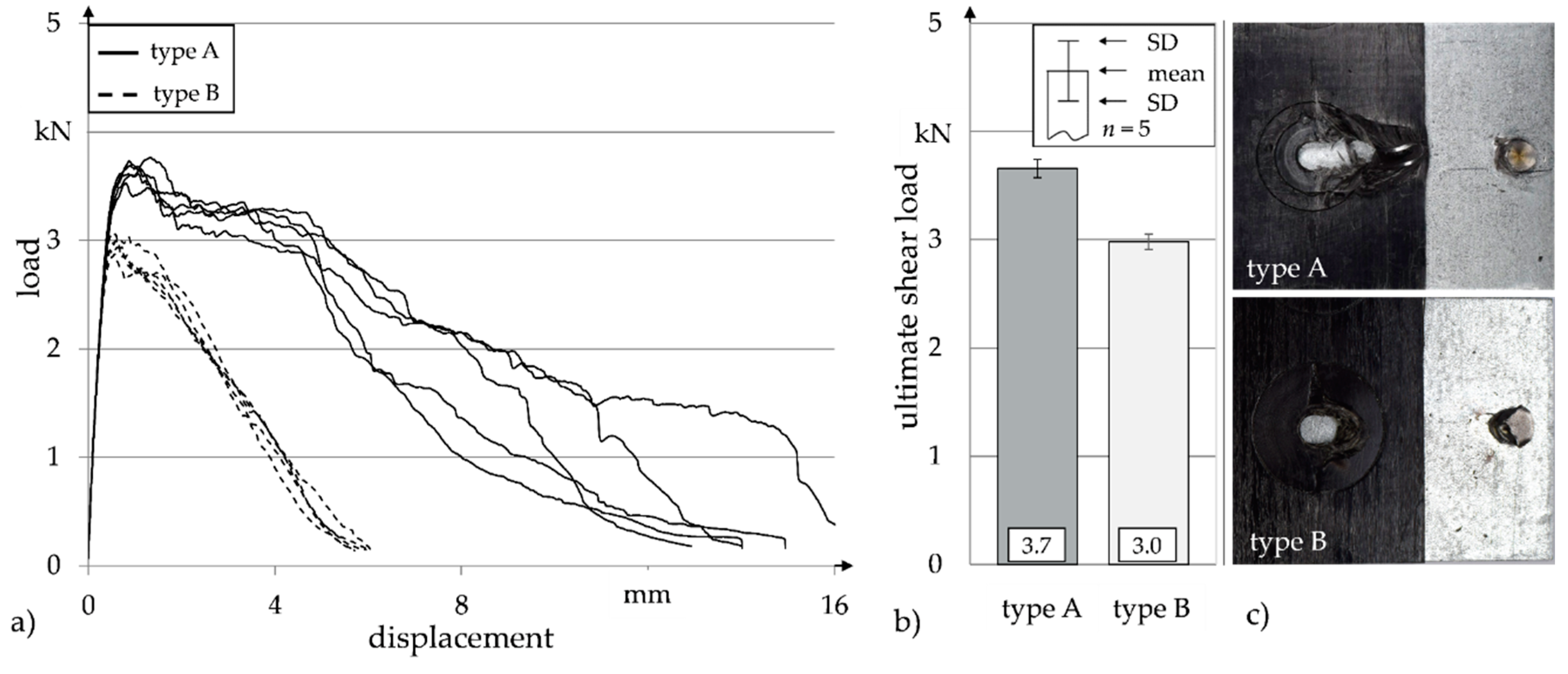
For further investigation of the load-bearing capacity of the joints, shear tests on single-lap joints were carried out under quasi-static load application on five specimens each for both types of weld inserts. The corresponding load-displacement curves, evaluated arithmetic means regarding the ultimate shear loads, the corresponding standard deviations (SD) and exemplary failure pictures of the specimens are shown in
Figure 11.
It can be seen that the ultimate shear load of the welded joints using weld insert type A is 3.7 kN on average with a maximum displacement of 13 mm to15 mm. The average ultimate shear load of joints using type B weld inserts is significantly lower (3.0 kN) with a maximum displacement of approximately 5 mm to 6 mm. This phenomenon can be explained by the corresponding failure characteristics. For type A insert, the failure behaviour of the specimens is characterised by the deformation with subsequent peeling off of the element head. Due to the fact that the specimen bend during the shear tests, the joint is loaded with an additional bending moment, which causes the flat head of the weld insert to be deformed before breaking off. Thus a bearing failure in the TPC is induced before the remaining element shank is unbuttoned, which explains the higher load-bearing capacity and in particular the increased displacement at failure. In contrast to that the smaller element head of the type B insert merely deforms during the shear test. Due to the smaller head diameter, the weld insert unbuttons from the TPC at lower load and lower displacement.
Table 3 summarises the mechanical characteristics of embedded weld inserts and welded joints as well as geometric sizes of the weld nuggets for both weld insert types.
4. Discussion
Microscopic examinations of cross sections of embedded weld inserts before REW verified a complete filling of the undercut with reinforcing fibres and matrix for both types of weld inserts. Furthermore, the weld inserts are well positioned with the shank tip protruding from the laminate to enable the subsequent welding process. Thus, the selected process parameters for process-integrated embedding of weld inserts into TPC (cf.
Table 1) could be confirmed as suitable for further investigations. The developed technology can be applied to other types of TPC in terms of matrix material as well as architecture and material of the reinforcement. For this purpose, the process parameters such as the heating temperature of the TPC sheet and the mould temperature need to be adjusted accordingly.
For an application of the developed technology, especially in series production, the joint strength of the embedded weld inserts and the TPC component must be high enough to provide reliable handling of the component up to the final part assembly by REW. Due to the larger undercut, the measured ultimate push-out load of type A with 1.7 kN is higher than type B with 0.8 kN. For the further handling process, the push-out loads are considered high enough for both types of weld inserts.
For the subsequent welding process, suitable process parameters were determined by numeric welding simulations, which were verified by the analysis of etched microsections. The shape and diameter of the weld nuggets were within the range predicted by the numeric simulation. With these types of welding simulations, a prediction of suitable process parameters can be obtained rapidly for applications with alternative materials or sheet thicknesses. In this context, the short welding times of 40 ms are particularly notable, which promise efficient processing.
In chisel tests, a sufficient strength of the welded joints could be determined, as the failure mode matched the aspired failure for REW, which is unbuttoning of the weld nugget from the steel sheet or unbuttoning of the TPC. Tensile test using a weld stud welded on the head of the insert to transfer the tensile load will be carried out in order to quantify the ultimate strength of the weld nugget between the insert and the steel sheet.
The ultimate shear load of the welded joints is higher for weld insert type A (3.7 kN) as compared to type B (3.0 kN). This is due to the significantly smaller countersunk head of type B compared to the head geometry of type A that protrudes from the composite surface as a disturbing contour. The load bearing capacity could be further increased by adjusting the head geometry, for example by increasing the head thickness. This could change the failure behaviour under shear load to a laminate bearing before element pull-out of the TPC. In addition, cross-tension tests will be carried out for further evaluation of the load bearing capability.
It could be shown that high-quality joints can be achieved with the developed technology. This provides the opportunity to use conventional spot-welding guns in established metal-oriented processes for TPC as well. Compared to other technologies using weld inserts (such as [
14]), the proposed approach allows the embedding of the weld insert during composite component manufacture without an additional process. Thereby the embedding of the weld insert does not require the preparation of a pre-hole in the TPC. For these reasons, the developed technology offers an excellent opportunity to integrate TPC into steel dominated multi-material systems. Of particular interest are fields of application where resistance spot welding is already implemented in series production, such as in the automotive industry.
5. Conclusions
TPC components can be welded to steel sheets by using embedded weld inserts as an interface. It could be shown, that weld inserts can be embedded in TPC during compression moulding in high quality and without fibre damage. Push-out tests before REW confirmed that the joint strength is high enough for further handling processes.
For the subsequent welding process, suitable process parameters were determined by numeric welding simulations. The ultimate shear load of the welded joints is significantly dependent on the head design of the embedded weld inserts. By analysing the quality and strength of the joints after the different process steps, it could be shown that high-quality joints can be achieved with this innovative technology.
Author Contributions
Process-integrated embedding of weld inserts in TPC, J.T.; analysis of the joint before welding, J.T.; simulation of the welding process and welding, J.V.; mechanical testing of welded joints, J.V.; writing and visualization, J.T. and J.V.; writing—review, R.K., M.G., and G.M.; funding acquisition J.T., J.V., R.K., M.G., and G.M.; project administration, M.G. and G.M. All authors have read and agreed to the published version of the manuscript.
Funding
The research project “Entwicklung multifunktionaler Schnittstellen zum Verbinden von FKV mit Metallen unter Nutzung etablierter Fügeverfahren” of the European Research Association for Sheet Metal Working (EFB) is carried out in the framework of the industrial collective research programme (IGF No. 20870 BG/EFB No. 08/119). It is supported by the Federal Ministry for Economic Affairs and Energy (BMWi) through the AiF (German Federation of Industrial Research Associations eV) based on a decision taken by the German Bundestag.
Conflicts of Interest
The authors declare no conflict of interest.
References
- Behrens, B.-A.; Raatz, A.; Hübner, S.; Bonk, C.; Bohne, F.; Bruns, C.; Micke-Camuz, M. Automated Stamp Forming of Continuous Fiber Reinforced Thermoplastics for Complex Shell Geometries. Procedia CIRP 2017, 66, 113–118. [Google Scholar] [CrossRef]
- Modi, S.; Stevens, M.; Chess, M. Mixed Material Joining—Advancements and Challenges; Center for Automotive Research: Ann Arbor, MI, USA, 2017. [Google Scholar]
- Schmid, D.; Neudel, C.; Zäh, M.F.; Merklein, M. Pressschweißen von Aluminium-Stahl-Mischverbindungen. Lightweight Des. 2012, 5, 14–19. [Google Scholar] [CrossRef]
- Meschut, G.; Janzen, V.; Olfermann, T. Innovative and highly productive joining technologies for multi-material lightweight car body structures. J. Mater. Eng. Perform. 2014, 23, 1515–1523. [Google Scholar] [CrossRef]
- Joesbury, A.M.; Colegrove, P.A.; Rymenant, P.V.; Ayre, D.S.; Ganguly, S.; Williams, S. Weld-bonded stainless steel to carbon fibre-reinforced plastic joints. J. Mater. Process. Technol. 2018, 251, 241–250. [Google Scholar] [CrossRef]
- Roth, S.; Warnck, M.; Coutandin, S.; Fleischer, J. RTM Process Manufacturing of Spot-weldable CFRP-metal Components. Lightweight Des. Worldw. 2019, 5, 18–23. [Google Scholar] [CrossRef]
- Shah, B.; Frame, B.; Dove, C.; Fuchs, H. Structural Performance Evaluation of Composite-to-Steel Weld Bonded Joint. In Proceedings of the 10th Annual Automotive Composites Conference and Exhibition, Troy, MI, USA, 15–16 September 2010; pp. 545–561. [Google Scholar]
- Holtschke, N.; Jüttner, S. Joining lightweight components by short-time resistance spot welding. Weld. World 2017, 61, 413–421. [Google Scholar] [CrossRef]
- Meschut, G.; Hahn, O.; Janzen, V.; Olfermann, T. Innovative joining technologies for multi-material structures. Weld. World 2014, 58, 65–75. [Google Scholar] [CrossRef]
- Meschut, G.; Matzke, M.; Hoerhold, R.; Olfermann, T. Hybrid technologies for joining ultra-high-strength boron steels with aluminum alloys for lightweight car body structures. Procedia CIRP 2014, 23, 19–23. [Google Scholar] [CrossRef]
- Herwig, A.; Horst, P.; Schmidt, C.; Pottmeyer, F.; Weidenmann, K.A. Design and mechanical characterisation of a layer wise build AFP insert in comparison to a conventional solution. Prod. Eng. 2018, 12, 121–130. [Google Scholar] [CrossRef]
- Weykenat, J.; Denkena, B.; Horst, P.; Meiners, D.; Schmidt, C.; Groß, L.; Herwig, A.; Nagel, L.; Serna, J. Local Fiber-Metal-Laminate used as Load Introduction Element for Thin-Walled CFRP Structures. In Proceedings of the 4th International Conference Hybrid 2020 Materials and Structures, Web Conference, Germany, 28–29 April 2020. [Google Scholar]
- Hufenbach, W.; Adam, F.; Kupfer, R. A novel textile-adapted notching technology for bolted joints in textile-reinforced thermoplastic composites. In Proceedings of the ECCM, Budapest, Hungary, 6–7 June 2010; pp. 1–9. [Google Scholar]
- Obruch, O.; Jüttner, S.; Ballschmiter, G.; Kühn, M.; Dröder, K. Production of hybrid FRP/steel structures with a new sheet metal connecting element. Biul. Inst. Spaw. 2016, 5, 60–66. [Google Scholar]
- Troschitz, J.; Kupfer, R.; Gude, M. Experimental investigation of the load bearing capacity of inserts em-bedded in thermoplastic composites. In Proceedings of the 4th International Conference Hybrid 2020 Materials and Structures, Web Conference, Germany, 28–29 April 2020; pp. 249–254. [Google Scholar]
- Troschitz, J.; Kupfer, R.; Gude, M. Process-integrated embedding of metal inserts in continuous fibre reinforced thermoplastics. Procedia CIRP 2019, 85, 84–89. [Google Scholar] [CrossRef]
- Kupfer, R. Zur Warmlochformung in Textil-Thermoplast-Strukturen—Technologie, Phänomenologie, Modellierung. Ph.D. Thesis, Technische Universität Dresden, Dresden, Germany, 2016. [Google Scholar]
- Cetin, M.; Thienel, M. Large-series Production of Thermoplastic Door Module Carriers. Lightweight Des. Worldw. 2019, 12, 12–17. [Google Scholar] [CrossRef]
- DIN EN 10268 Cold Rolled Steel Flat Products with High Yield Strength for Cold Forming—Technical Delivery Conditions; Deutsches Institut für Normung E.V.: Berlin, Germany, 2013.
- DIN EN 10025-2 Hot Rolled Products of Structural Steels—Part 2: Technical Delivery Conditions for Non-Alloy Structural Steels; Deutsches Institut für Normung E.V.: Berlin, Germany, 2019.
- DIN EN ISO 10447 Resistance Welding—Testing of Welds—Peel and Chisel Testing of Resistance Spot and Projection Welds; Deutsches Institut für Normung E.V.: Berlin, Germany, 2015.
- DVS/EFB 3480-1 Testing of Properties of Joints—Testing of Properties of Mechanical and Hybrid (Mechanical/Bonded) Joints; DVS: Düsseldorf, Germany, 2007.
- Böddeker, T.; Chergui, A.; Ivanjko, M.; Gili, F.; Behrens, S.; Runkel, D.; Folgar, H. Joining TWIP—TWIP-Steels for Multi-Material Design in Automotive Industry Using Low heat Joining Technologies. In Proceedings of the 6th Fügetechnische Gemeinschaftskolloquium, Munich, Germany, 7–8 December 2016; pp. 77–82. (In German). [Google Scholar]
- Roth, S.; Hezler, A.; Pampus, O.; Coutandin, S.; Fleischer, J. Influence of the process parameter of resistance spot welding and the geometry of weldable load introducing elements for FRP/metal joints on the heat input. J. Adv. Join. Process. 2020, 2, 100032. [Google Scholar] [CrossRef]
- Schmal, C.; Meschut, G. Process characteristics and influences of production-related disturbances in resistance element welding of hybrid materials with steel cover sheets and polymer core. Weld. World 2020, 64, 437–448. [Google Scholar] [CrossRef]
Figure 1.
Schematic illustration of process-integrated embedding of weld inserts in thermoplastic composites (TPC): (a) warming up the TPC sheet, (b) closing the compression mould, (c) shifting forward the pin tool, (d) recompressing the squeezed-out material by the counterpunch, (e) demoulding of the TPC specimen.
Figure 2.
Schematic illustration of the temperature curve during process-integrated embedding of weld inserts in TPC with associated process steps from
Figure 1. (
a), TPC test specimen with integrated weld insert type A: top view (
b) and bottom view (
c).
Figure 2.
Schematic illustration of the temperature curve during process-integrated embedding of weld inserts in TPC with associated process steps from
Figure 1. (
a), TPC test specimen with integrated weld insert type A: top view (
b) and bottom view (
c).
Figure 3.
Prototypic weld inserts for process-integrated embedding: (a) type A, (b) type B.
Figure 3.
Prototypic weld inserts for process-integrated embedding: (a) type A, (b) type B.
Figure 4.
Two-dimensional (2D) axisymmetric model used for the simulation of the resistance element welding process.
Figure 4.
Two-dimensional (2D) axisymmetric model used for the simulation of the resistance element welding process.
Figure 5.
(a) Schematic illustration of the push-out test setup, (b) geometry of single-lap shear specimen (lo: overlap length); 1: pressure punch, 2: weld insert, 3: TPC specimen, 4: exchangeable steel clamping, 5: base steel plates, 6: steel specimen.
Figure 5.
(a) Schematic illustration of the push-out test setup, (b) geometry of single-lap shear specimen (lo: overlap length); 1: pressure punch, 2: weld insert, 3: TPC specimen, 4: exchangeable steel clamping, 5: base steel plates, 6: steel specimen.
Figure 6.
Analysis of the joining zone after embedding: (a) type A, (b) type B.
Figure 6.
Analysis of the joining zone after embedding: (a) type A, (b) type B.
Figure 7.
Results of the push-out tests: (a) load-displacement curves, (b) typical failure behaviour.
Figure 7.
Results of the push-out tests: (a) load-displacement curves, (b) typical failure behaviour.
Figure 8.
Validation of the welding simulation model via comparison: (a) of the shapes, (b) of the sizes of experimentally and simulatively generated weld nuggets.
Figure 8.
Validation of the welding simulation model via comparison: (a) of the shapes, (b) of the sizes of experimentally and simulatively generated weld nuggets.
Figure 9.
Simulative generated weldability lobes for weld insert type A (a) and type B (b).
Figure 9.
Simulative generated weldability lobes for weld insert type A (a) and type B (b).
Figure 10.
Analysis of the joining zone after resistance element welding (REW) (top: micrographs of welded joints using weld insert type A (a), and type B (b), bottom: pictures of welded specimen using weld insert type A (c) and type B (d) after chisel tests).
Figure 10.
Analysis of the joining zone after resistance element welding (REW) (top: micrographs of welded joints using weld insert type A (a), and type B (b), bottom: pictures of welded specimen using weld insert type A (c) and type B (d) after chisel tests).
Figure 11.
Results of single-lap shear tests under quasi-static load for both types of weld inserts: (a) load-displacement curves, (b) ultimate shear load, (c) characteristic failure behaviour.
Figure 11.
Results of single-lap shear tests under quasi-static load for both types of weld inserts: (a) load-displacement curves, (b) ultimate shear load, (c) characteristic failure behaviour.
Table 1.
Manufacturing parameters of the process-integrated embedding of weld inserts in TPC.
Table 1.
Manufacturing parameters of the process-integrated embedding of weld inserts in TPC.
| Heating temperature TPC | 210 °C |
| Mould temperature | 40 °C |
| Moulding pressure | 8 bar |
| Feed force of the pin tool | 2.5 kN |
| Feed force of the counterpunch | 5 kN |
Table 2.
Material specification.
Table 2.
Material specification.
| TPC | Unidirectional semi-finished product | Celstran® CFR-TP PP-GF70 |
| | Fibre volume content | 45 vol.-% E-glass |
| | Matrix | Polypropylene (PP) |
| | Laminate thickness | 2 mm |
| | Laminate structure | [(0°/90°)2]s |
| Steel sheet | Material | HC340LA ([19]) |
| | Sheet thickness | 1.5 mm |
| Weld insert | Material | S235JR ([20]) |
Table 3.
Mechanical properties of joints and geometric sizes of weld nuggets.
Table 3.
Mechanical properties of joints and geometric sizes of weld nuggets.
| Parameter | Type A | Type B |
|---|
| push-out load before welding (mean) | 1.7 kN | 0.8 kN |
| nugget height (mean) | 1.2 mm | 1.3 mm |
| nugget diameter (mean) | 3.9 mm | 4.4 mm |
| ultimate shear load (mean) | 3.7 kN | 3.0 kN |
| Publisher’s Note: MDPI stays neutral with regard to jurisdictional claims in published maps and institutional affiliations. |
© 2020 by the authors. Licensee MDPI, Basel, Switzerland. This article is an open access article distributed under the terms and conditions of the Creative Commons Attribution (CC BY) license (http://creativecommons.org/licenses/by/4.0/).


