Article

Drill Hole Orientation: Its Role and Importance on the Compression Response of Pure Magnesium

by
Anirudh Venkatraman Krishnan
1,
Penchal Reddy Matli
1,
Gururaj Parande
1,
Vyasaraj Manakari
1,
Beng Wah Chua
2,
Stephen Chee Khuen Wong
2,
Senthil Kumar Anantharajan
1,
C. Y. H. Lim
1 and
Manoj Gupta
1,*
1
Department of Mechanical Engineering, National University of Singapore, Singapore 117575, Singapore
2
Singapore Institute of Manufacturing Technology, Singapore 138634, Singapore
*
Author to whom correspondence should be addressed.
Appl. Sci. 2020, 10(20), 7047; https://doi.org/10.3390/app10207047
Submission received: 14 September 2020 / Revised: 2 October 2020 / Accepted: 6 October 2020 / Published: 11 October 2020
(This article belongs to the Special Issue Metal Matrix Composites II)

Abstract

:

Featured Application

Development of hybrid cellular structures for aerospace component manufacturing and repair.

Abstract

Drilling is used in creating cylindrical through-holes for various applications. While optimizing drilling parameters is widespread, the effect of a drilled through-hole on the structural stability of components is not fully documented. The base material, along with other parameters, such as drill diameter, drill location and its orientation affect structural stability. Since carrying out tests on different base materials can be time consuming, simulation software can instead be used to provide valuable information. However, the comparison between experiments and simulations gets difficult; hence, this study attempts to provide a basis for effective comparison by studying simulations and compression tests, comparing the two, and documenting the role of drill hole orientation on the compressive response of magnesium, a material with immense potential in light-weight components. Simulations and experiments were carried out on three through-hole orientations and were compared to the undrilled scenario. Results demonstrate significant differences in compression behaviour. While the compressive yield strength increased in all three drill orientations, ultimate strength and ductility was reduced in horizontal and angular drill hole orientations. These observations, therefore, provide valuable insight into choosing the right orientation for different applications.

1. Introduction

Designing mechanical engineering equipment for special applications requires an extensive understanding of the environment that it is being designed for. In addition, certain real-time operational challenges require traditional analytical methods to be verified using extensive testing and qualification programs [1,2]. It is well known that most equipment is an assembly of components with each individual component being designed for effective load bearing and transfer. Steels and other ferrous alloys have been the predominant choice of material to manufacture these components in the transportation sector due to their superior mechanical properties and excellent wear and corrosion resistance [3,4,5]. However, equipment made out of ferrous alloys is heavy [6] which results in unnecessary deadweight in moving components, subsequently increasing fuel consumption. Reports indicate that there continues to be an increase in carbon dioxide emission despite various governmental policies [7] with almost a quarter of the greenhouse gases associated with emissions from road transport vehicles [8]. Therefore, reducing emissions, improving fuel efficiency, and reaching carbon neutrality is crucial for the future.
Materials, such as aluminium and magnesium have been studied for a long time to replace heavier metals and alloys, such as iron and steel [9,10,11]. Aluminium has found immense applications in automotive parts, including in chassis, structure, and several components, such as welded tubes and heat exchangers [10]. Aluminium alloys and aluminium-based metal matrix composites have also found application in the aerospace industry, where weight saving results in enormous fuel savings and consequently helps reduce the carbon footprint, making it environmentally friendly [12,13,14].
In an attempt to further reduce weight, materials engineers have also introduced new alloys, such as high-strength steel, novel magnesium alloys, and plastics of different kinds to be tested and used in innovative and new automotive applications [15,16,17]. Magnesium, given its excellent vibration absorption capacity and widespread availability, has also found increased use in applications, such as in power tools, lawn and garden equipment, sports, aerospace and automotive equipment as well [18]. The wear resistance of magnesium-based alloys is also being studied to quantify the expected wear in a component over its lifetime [19,20,21]. Magnesium alloys have also found profound applications in electronics with the latest devices from brands like Microsoft (Surface Book and Surface Pro [22]), LG (Gram laptops [23]) and Fujistu (UH-X laptops [24]) employing magnesium alloys to maintain structural integrity while possessing an ultra-portable weight and customization. Over the last few decades, engineers, using finite element analyses, have also been able to optimize the topology of several components, thereby reducing weight [25,26]. While traditional manufacturing processes have limitations to the extent of making material removal possible, the flexibility to have joints and an option of 3D printing has given engineers even more flexibility to design and develop complicated designs with ease [27,28,29]. Nevertheless, 3D printing may not be possible in all scenarios and for such cases, scientists have even introduced novel methods for drilling micron sized holes while improving tool life by providing efficient cooling methods [30,31].
However, design and material selection form a part of the initial design phase. While material properties, such as mechanical strength, Young’s modulus, wear, and corrosion resistance are critical, the optimization of component design is equally crucial for lightweight applications. Once a component is manufactured, real-time monitoring of equipment becomes necessary as it provides valuable inputs into the design caveats. From identifying the time to failure in engineered components, such as pipelines [32,33] and aerospace equipment [34], to medical devices, such as smart bandages [35], the information obtained from real-time monitoring forms an integral part of the design process and helps optimize the design to meet various requirements while avoiding predictable disasters. In all these cases, access to the region of interest is crucial. The easiest way to get access to these monitoring locations is by drilling a hole through the object of interest and placing necessary sensors in them to obtain real-time information. However, common sense dictates that this ease of access should not come at the expense of the strength of the component.
Research into the impact of this drill/access hole on the strength of a component is surprisingly minimal in this regard, especially when it comes to light-weight materials and in the aerospace sector. Our earlier work [36] evaluated the effect of drill hole diameter in a vertical orientation on the strength to weight ratio of magnesium. It also detailed how the drill hole deforms under a compression load to give information on the size of sensors that can be placed inside. The results from that study indicated that the component need not necessarily experience a weakening in strength but can instead experience an improved mechanical response to compressive loads (i.e., when the drill hole diameter is 1.5 mm in an 8 mm cylindrical sample with d/D = 0.1875). That study was performed in a single orientation and suggested a hypothesis correlating light-weighting and strength enhancement. It is common sense that the orientation of the drill hole as well as its location can significantly affect the mechanical strength of the component. However, the lack of research in this regard implies that the influence of the orientation of a drill hole on the strength retention of a component warrants study.
Accordingly, this study explores the effect of drill hole orientation on the compressive response of a cylindrical component while maintaining the drill hole diameter at 1.5 mm (the optimum drill hole diameter in the previous study). While several materials are employed in compressive applications, this study chose pure magnesium as the material of interest due to its versatile application in light-weighting. The effects of vertical, angular, and horizontal drill holes on the compressive strength of pure magnesium have been compared with monolithic or undrilled magnesium. The question of whether this compressive behaviour depends on the material itself warrants a separate study for the future.

2. Materials and Methods
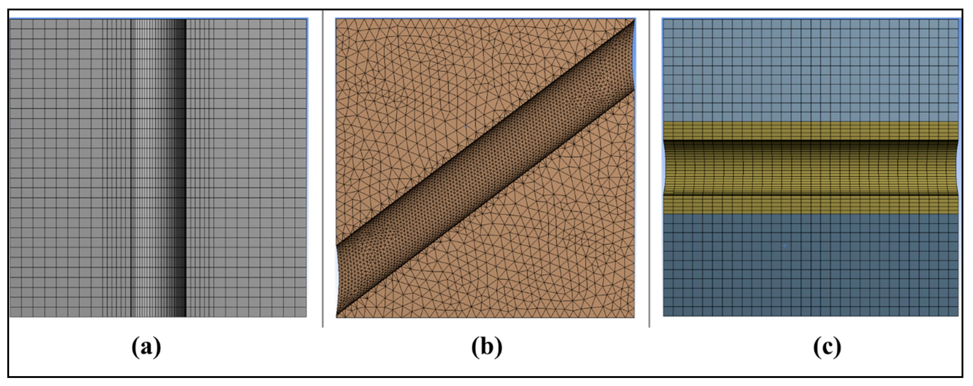
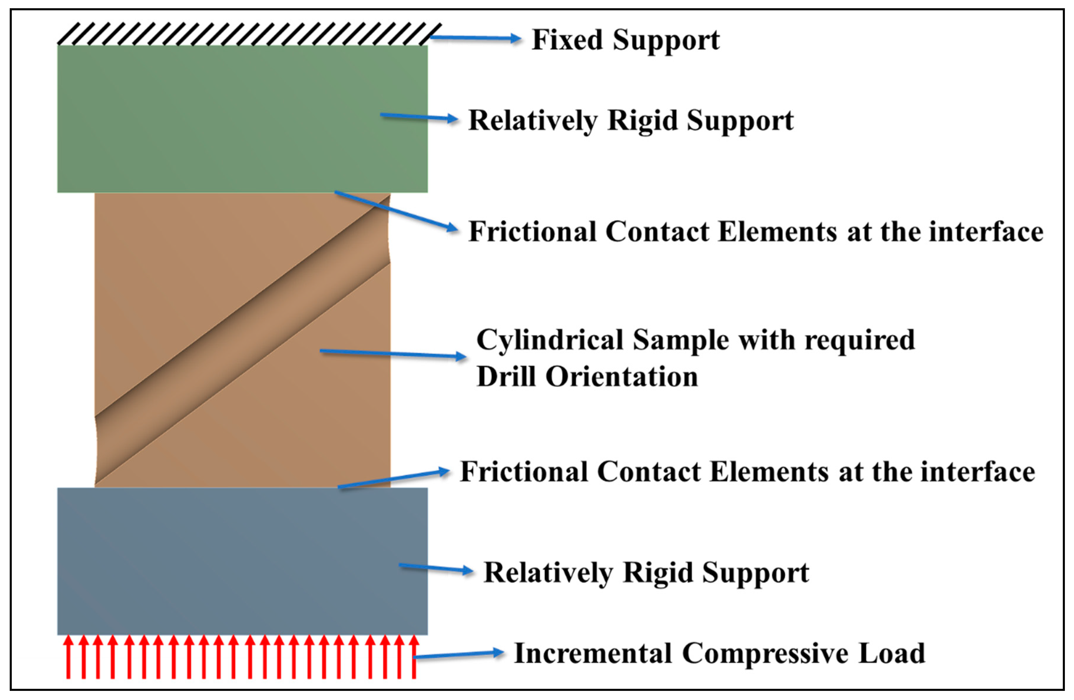
2.1. Simulations

2.1.1. Simulation Parameters

For a specimen with a vertical drill hole orientation, Matli et al. [36] reported that a 1.5 mm diameter drill hole offered optimum material properties. Hence, to maintain a comparison, three different drill orientations (vertical, angular, and horizontal) were analysed in this study while maintaining a drill diameter of 1.5 mm. In the case of vertical and horizontal drills, the drill position was centralized in the sample. However, for the angular drill condition, due to practical difficulty in obtaining a 45° orientation (i.e., drilling hole on the edge of a sample while maintaining stability), a drill position, slightly lower than the edge of the sample, was chosen, as shown in Figure 1b.
Similar to previous experiments conducted by Matli et al. [36], 8 mm diameter cylinders with 8 mm height were considered in these simulations as well. This resulted in a hole length of 8 mm each on the vertical drill and horizontal drill cases (Figure 1a,c) while it resulted in 9.94 mm in the angular drill scenario (Figure 1b). These lengths were measured along the axis of the drill hole. The above models were built in ANSYS DesignModeler, following which, they were meshed using structural hexahedral and tetrahedral elements in ANSYS Mechanical v19. The vertical, angular, and horizontal drill hole models had 50,200, 245,292, and 77,922 elements, respectively, with a minimum element size of 0.1 mm around the hole. A visual representation of the mesh around the hole is shown in Figure 2.
The material behaviour was set to be deformable in elastic and plastic regions with a Young’s Modulus of 45 GPa, a Poisson’s ratio of 0.28 (as reported by Parande et al. [37]), and a true stress–true strain curve for plastic behaviour obtained from monolithic magnesium experiments (i.e., with no drill hole). The engineering stress–strain curve for monolithic magnesium, from which true stress–true strain curve was derived, is represented in Figure 3.
To simulate compression testing, a rigid top support with a fixed constraint was used to restrain the movement of the cylinder in the upward direction while the compressive load was applied using a rigid plate at the bottom of the sample. Additionally, deformable–deformable frictional contact pairs with a coefficient of friction of 0.3 were used in the presence of an augmented Lagrange contact algorithm with contact detection at every Gaussian integration point to ensure that simulations mimic experimental conditions. Incremental compressive loads up to 15,000 N were applied on the bottom support in each case to study their deformation behaviour. This is illustrated in Figure 4. With this setup, a Newton–Raphson based elastic–plastic analysis was carried out using a sparse matrix direct solver with large deformation mode active.

2.1.2. Analysis Procedure Post Simulation

Since the samples are being subjected to compressive loads, shear failure is expected to dominate in this loading condition and thus, the maximum shear stress plots are presented to identify the high-stress regions and elucidate their three-dimensional distribution around the drilled holes, which are areas of stress concentration. However, stress development in a component is never uniform with different parts of the component experiencing different levels of plastic deformation. Simulation software can provide how much the volume of the solid experiences a particular level of plastic deformation/strain. Since the specimen is subjected to variable loads during experiments and a constant load during simulation, to make suitable comparisons between simulations and experiments, after every simulation, the plastic zone volumes at a particular load-interval (1500 N) were rendered in the cylinder. However, to make a suitable comparison between drill orientations using only simulations, the plastic deformation was compared at a load of 9000 N as this was midway through the plastic deformation (between 3000 N or ~60 MPa, the CYS of monolithic magnesium and 15,000 N or ~300 MPa, the maximum load applied, as shown in Figure 3), thereby accounting for both elastic as well as plastic deformations in all three orientations. At 9000 N, in monolithic 8 mm diameter cylinders, the engineering stress can be calculated to be approximately 180 MPa. This corresponds to a true strain of ~9% in monolithic magnesium. Hence, the plastic zone volume above 9% strain was identified for each case first. While comparing the results, if for a particular case, the plastic zone volume obtained through this method was found to be lesser than another case, then it was deemed that the latter case would fail faster as a larger region reaches failure strains faster without allowance for stress redistribution. This allows us to rank the drill hole orientations on the compressive response of the component.

2.2. Experimental Procedure

2.2.1. Materials and Processing

Magnesium turnings of 99.9% purity (procured from Acros Organics, NJ, USA) was utilized as the raw material. These turnings were placed in a graphite crucible, heated to a temperature of 750 °C in an argon (Ar) atmosphere, and then poured through a 10 mm diameter nozzle into a 40 mm diameter crucible using a Disintegrated Melt Deposition (DMD) technique. The cast ingots were then turned into a 36 mm diameter billet using a CNC lathe to smooth off any rough edges. Following this, the billets were homogenized for 1 hour at 350 °C and then hot extruded resulting in rods of 8 mm diameter. These pure Mg rods were then subjected to drilling on a Makino V55 3-axis CNC vertical machining centre with a maximum feed rate of 30 mm/min at a high spindle speed (10,000 rpm) using a 1.5 mm drill diameter.

2.2.2. Material Characterization

The compressive properties were determined as per ASTM: E9-09 standard using a fully automated servo-hydraulic mechanical testing machine (50 kN MTS 810) on cylindrical test samples of length 8 mm and diameter 8 mm—i.e., l/d ratio ~1. A constant strain rate of 0.0000833/s was used for all the samples and the strain rate was measured based on the cross-head speed. Five samples per orientation were tested to arrive at the stress–strain behaviour. A Scanning Electron Microscope (SEM, Kyoto, Japan) was used to analyse the fractured samples for determining the mode of failure under compression loading.

3. Results and Discussions

3.1. Simulation Results

Using simulations, a sound understanding of the effect of drill hole orientation can be obtained by discussing three aspects. Since drilled magnesium can be treated as a component instead of a material, the first aspect that would be discussed is the development of shear stresses. Changes in the orientation of shear stress can spark a difference in macroscopic failure initialization while microscopic modes can only be confirmed through experimentation. Though shear mode is dominant under compression, flex in a component can sometimes aid in load-bearing [36] and hence, identifying the volume of the component that experiences strains above 9% (as discussed in Section 2.1.2) can provide an insight into whether the presence of high shear regions would initiate plastic failure. While these aspects are crucial, any changes to the two aspects discussed above are known to affect deformation patterns. Hence, the last aspect discussed would be on the macroscopic deformation patterns.

3.1.1. Development of Shear Zones

Maximum shear stress plots were obtained at a compressive load of 9000 N for all drill-hole orientations and stresses above 120 MPa (i.e., 0.4*UTS where UTS = 300 MPa for monolithic magnesium) were coloured red. These plots are shown in Figure 5. Figure 5A shows that, in the case of vertical drill hole orientation, the majority of the volume is under the stress of 120 MPa. However, Figure 5B1,2 and Figure 5C1–3 show a significant region to be above the 120 MPa stress. In the angular drill hole orientation, the majority of the volume experiences shear stresses less than 80 MPa (fourth colour on the contour band). The region experiencing stresses above 120 MPa is found to be concentrated around the hole. Figure 5B1 illustrates the spatial distribution of the low and high shear stress regions. The red region in Figure 5B2 gives a 3D representation of this high-stress region and also hints at a possible direction in which macroscopic failure could take place in the sample with a drill hole in angular orientation.
As the drill hole orientation changes to the horizontal direction, the maximum shear stress contours shape themselves in a pattern that is quite similar to the vertical drill hole orientation albeit with slight differences. Figure 5C1 shows a significant presence of high-stress regions in the horizontal drill hole orientation developing at a particular angle to the sample, which was minimal in the vertical drill hole orientation. In the case of a horizontal drill hole orientation, the hole itself acts as a stress concentration, resulting in compressive stresses at the left and right of the hole and tensile stresses at the top and bottom of the hole giving rise to additional shear stresses in between. The orientation of the region with stresses above 120 MPa is better identified in Figure 5C2,3. A common observation in all three drill orientations is that the maximum shear stress region bulges at the centre of the sample.

3.1.2. Development of Plastic Zones

While a pictorial representation of the shear stress region provides valuable insight into the ideal drill hole orientation in compression, a quantitative representation can be obtained by studying the development of plastic zones within the sample. The development of this plastic zone is, in turn, crucial to the deformation behaviour, as well as the load-bearing capacity of a sample. In general, the presence of a drill hole is expected to act as a precursor for the weakening of the structure and the plastic zone is expected to first develop around these drill holes as they represent regions of stress concentrations. However, Matli et al. [36] showed that the size of the hole dictates the load-bearing capacity analogous to how the size, radius, and position of a crack determines the time to failure in components. Hence, to make a comparison of load-bearing capacities between the three orientations, the plastic zone volumes were evaluated at 9000 N, a load that is halfway between elastic zone and load at failure (as detailed in Section 2.1.1). At this load, the true strain in monolithic magnesium was found to be around 9% and hence, plastic zone volumes above 9% strain were compared and the same is presented in Table 1.
Initial impressions from Table 1 are that both angular and horizontal drill hole orientations experience significantly larger plastic zone volumes above the critical strain of 9% when compared to the monolithic and vertically drilled hole. This was evident even in the shear stress plots in the earlier section. The vertical drill hole orientation observes a larger plastic zone volume above 9% strain when compared to monolithic condition while having a lower total volume as the drill hole, by itself, introduces a stress concentration and the area around the hole, therefore, observes higher stresses and strains which was absent in the monolithic condition. The angular drill hole orientation sees the largest plastic zone volume above this critical strain while having the lowest total volume. So, one may jump to the conclusion that the angular drill hole scenario presents the worst-case scenario as a higher percentage of its volume sees large plastic strains. However, these values do not give a complete picture of the load-bearing capacity of these drill orientations.
While visual understanding of plastic zone development is difficult to report with incremental loads, an easier way to quantify and understand this plastic zone development is to measure what part of the volume has exceeded the corresponding strain limit at any given load. To do so, the true strains in the monolithic magnesium sample were evaluated at loads of 1500 N increments and the plastic zone volume above these strains for each drill hole orientation were arrived at before comparison. Using this method, the development of plastic zone volume is presented in Figure 6.
As the compressive load increases, the behaviour of vertical drill hole orientation is almost identical to the monolithic condition (no drill) albeit with a slightly larger plastic zone as shown in Figure 6. The horizontal and angular drill hole orientations also follow a remarkably similar plastic zone development pattern but also observe significantly higher plastic zone volumes at all loads when compared to vertical and monolithic (no drill) conditions. While angular drill hole orientation observes the highest plastic zone volume above critical strain till about 12,700 N, beyond that load, the horizontal drill hole orientation starts to observe higher plastic zone volume above critical strain. While this is counter-intuitive, an element to remember is that the development of these plastic zone volumes occurs in cylinders with different drill hole lengths. As detailed earlier in Section 2.1, the length of the drill hole in the angular drill hole orientation is approximately 9.94 mm, while that of the horizontal and vertical drill hole orientations is 8 mm. This detail is important as the plastic zone develops around the drill hole as these holes act as stress concentration regions. Hence, the plastic zone development can be better represented as a normalized plastic zone area by calculating the value of the plastic zone volume divided by the length of the drill hole. This is demonstrated in Figure 7a.
A clear distinction can now be inferred on the load-bearing capacities of three drill hole orientations. From simulations, the first inference is that, at various loads, the vertical drill hole orientation provides better structural stability in compression when compared to angular and horizontal drill hole orientations, as it observes lower plastic zone volume above critical strain (Figure 6) as well as a smaller normalized plastic zone area over critical strain (Figure 7a). Figure 7b further illustrates this inference by showing how different the normalized plastic zone areas around the drill hole are at a 15,000 N compressive load. It is understood that the presence of larger plastic zone volumes above critical strain implies faster crack initiation/propagation around the drill hole leading to premature failure.

3.1.3. Macroscopic Changes in Deformation Patterns

In addition to the shear stress development, as Matli et al. [36] pointed out, the deformation of the hole can provide valuable information on which drill hole orientation is ideal. They also provide valuable information on whether sensors placed in these drill holes could observe any disruption to their regular function. Deformation patterns of the vertical hole orientation, shown in Figure 8A, illustrate similar behaviour to that of Matli et al. [36]. However, as the drill orientation changes to an angular orientation, though the entire sample undergoes compression, the deformation patterns are slightly different for the top half and bottom half of the hole. On the bottom left and top right corners of the component in Figure 8B, the stiffness of the component is comparatively lower due to the presence of the hole, resulting in higher deformations locally (as indicated by the arrows). This can generate an “S” shaped deformation pattern in the hole which may allow more energy absorption during compression. Finally, when the drill orientation is horizontal, the entire length of the drill hole sees a slightly uniform deformation pattern, as shown in Figure 8C1,2, demonstrating the deformation of the cross-section of the hole. A clearer picture of the tension and compression region mentioned in Section 3.1.1 is also visible in Figure 8C2.
Overall, from Figure 8, it is evident that there exists a plane about which the deformation patterns are mirrored and inverted, and from closer observation, we notice that this plane is aligned along the axis of the drill hole. Further, both angular drill hole orientation and horizontal drill hole orientations give rise to localized deformations within the component and away from the compression direction, resulting in decreased stability in the component when compared to the vertical drill hole orientation.

3.1.4. Summary of Simulation Results

In summary, using simulations, the following observations were made:
  • Though the maximum shear stresses developed around the drill hole in all three cases, the development and alignment are vastly different, paving the way for a difference in macroscopic failure orientation. However, microscopic failure modes can only be evaluated through experimentation (refer to Figure 5).
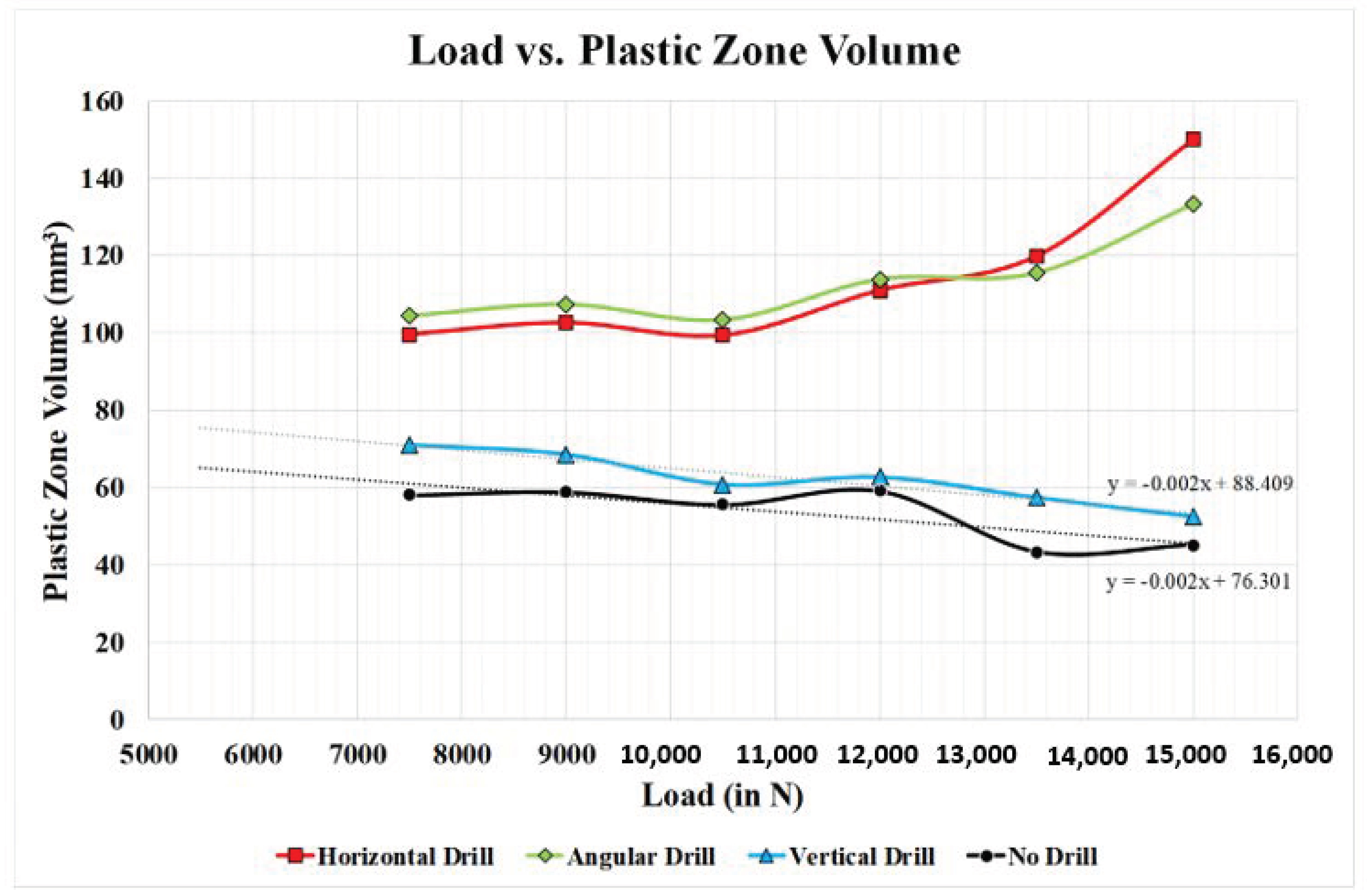
  • Comparing the volume of the component experiencing strains above critical strains and deriving the normalized plastic zone area helped rank the horizontal drill orientation as the weakest of the three orientations, followed by angular orientation being the next weakest (refer to Figure 6 and Figure 7).
  • The vertical orientation was ranked the strongest of the three as it showed the least deviation in deformation patterns and plastic zone development when compared to the monolithic condition (refer to Figure 6, Figure 7 and Figure 8) while angular and horizontal drill hole orientations imparted significant local deformation around the drill holes.

3.2. Experimental Results

3.2.1. Compression Testing

Experimentally observed effects of drill hole orientation on the compressive response of magnesium are presented in Figure 9. The primary mechanical properties obtained from the stress–strain curves for different drill hole orientations, such as compressive yield strength (CYS) (based on 0.2% offset), ultimate compressive strength (UCS) (the highest stress taken) and failure strain, which are compared to monolithic magnesium, as shown in Table 2.
For the vertical drill hole orientation, the CYS increased from 65 ± 1 MPa to 105 ± 2 MPa, a net 61% increase, and the UCS increased from 297 ± 4 MPa to 330 ± 3 MPa, a net 11% increase when compared to the undrilled samples. This shows an improvement in the load-bearing capacity of the sample. However, in the case of angular and horizontal drilled samples, while the CYS was found to increase by ~105% and ~86%, respectively, the UCS decreased by 18% and 25%, respectively. Further, compressive failure strains in angular and horizontal drill samples also exhibited a drop, as shown in Table 2. This implies that the component is not as stable as the vertical drill hole scenario.

3.2.2. Fractography Analyses

To evaluate whether a change in the mode of fracture was observed, fractographic analyses were conducted on the failure surface of each drill orientation (Figure 10). Fractography analysis using SEM micrographs revealed a shear mode of fracture in all three drill hole orientations as shown in Figure 10 indicating no change in microscopic failure mode. However, on a macroscopic scale, the monolithic and vertical drill hole samples failed at a 45° angle (see insets of Figure 10), while the angular drill hole and horizontal drill hole orientations failed at slightly different angles. The change in shear plane direction can be attributed to the development of shear, as discussed in Section 3.1.1 and shown in Figure 5.

3.2.3. Summary of Experimental Results

Experimentally, the following observations were made:
  • Compression tests showed the ductility and ultimate tensile strength reduced as the drill hole orientation changed from vertical to angular to horizontal, respectively.
  • The load to failure for each of these individual components indicates that the horizontal drill hole orientation fails first and the vertical drill hole orientation lasts the longest.
  • Another observation was that all three drill hole orientations increased the yield strength of the component if the 0.2% offset method was considered. This can be attributed to the lower stiffness of each of these components in general when compared to the monolithic condition, thereby giving rise to local flexure and local yield and thereby, longer duration to global yield.
  • Microscopic observations indicated that the presence of the drill hole did not change the microscopic deformation and failure mechanisms with the shear mode still being prevalent in all cases.
  • Macroscopic observation of the fractured sample indicated a difference in orientation of the final crack. While the monolithic and vertical drill hole orientations experienced near 45° failure crack propagation, the angular drill hole experienced a failure angle of more than 45° with the horizontal and horizontal drill orientations experienced a failure angle of less than 45° with the horizontal. These deviations are shown in the insets of Figure 10.

3.3. Reflections on Simulations and Experiments

Comparing the simulation results and the experimental results, we found good agreement between the two.
  • Both simulations and experiments predict the vertical drill hole orientation to be the strongest.
  • Simulations predict higher stress in the angular and horizontal drill hole components (Figure 5), while experiments also validate the same by showing higher stress in them for the same amount of engineering strain.
  • In the angular drill hole scenario, simulations can also approximately predict the failure orientation. Alignment of shear stresses around the hole (i.e., the red region in Figure 5B2) is along the same lines as the macroscopic failure crack in the inset of Figure 10C.
In essence, we noticed that the observations from simulations are backed by experimentation. This similarity gives particular importance to the use of computational software in determining the best possible design for a particular material. Since the shear mode of failure is prominent in compression testing, the increase in plastic zone size in conjunction with possible failure modes (including ease of shear due to controlled defect) could be the reason for the observed decrease in ultimate compressive strengths of angular and horizontally drilled samples.
Future studies could, therefore, make use of simulations first to predict the plastic zone development and shear stress orientations prior to carrying out experiments. Research on increasing the number of drill holes, changing the location of drill hole and their orientation has plenty of applications, especially in the real time monitoring of engineered components.

4. Conclusions

In this study, drilling experiments were carried out on pure Mg samples synthesized using the disintegrated melt deposition method followed by hot extrusion with a special emphasis on drill hole orientation. The simulation results in conjunction with experimental results suggest that the best combination of compressive properties is achieved in the vertical drill hole orientation. Experiments and simulations also concur that the horizontal drill hole scenario may be the worst-case scenario. Fractography shows that, no matter what the drill hole orientation is, the mode of failure continues to be shear dominated as no changes were observed in all three cases. Hence, choosing a controlled drill hole in the vertical orientation can either aid in improving the load-bearing capacities of cylindrical components.

Author Contributions

Conceptualization, B.W.C., S.C.K.W., S.K.A., C.Y.H.L. and M.G.; Formal analysis, A.V.K., P.R.M., G.P. and V.M.; Funding acquisition, B.W.C., S.C.K.W. and M.G.; Investigation, A.V.K., P.R.M., G.P. and V.M.; Methodology, A.V.K., P.R.M. and S.K.A.; Project administration, B.W.C., S.C.K.W., C.Y.H.L. and M.G.; Resources, S.K.A. and M.G.; Supervision, S.K.A., C.Y.H.L. and M.G.; Writing—original draft, A.V.K. and P.R.M.; Writing—review and editing, G.P., V.M. and M.G. All authors have read and agreed to the published version of the manuscript.

Funding

This research was supported by the Agency for Science, Technology, and Research (A*STAR), Singapore, under its program “Manufacturing of lightweight free-form shell, sandwich, and hybrid cellular structures for aerospace component manufacturing and repair” (WBS # R 265 000 638 305).

Conflicts of Interest

The authors declare no conflict of interest.

References

  1. Forsyth, A.; Saucier, B.J.; More, D.J.; Stawaisz, R.; Gill, D.; Younger, R. The Mechanical Engineering Challenges of Designing HP/HT Equipment. In Proceedings of the SPE Annual Technical Conference and Exhibition, Society of Petroleum Engineers, Anaheim, CA, USA, 1 January 2007; p. 9. [Google Scholar] [CrossRef]
  2. Smith, L. Control of corrosion in oil and gas production tubing. Br. Corros. J. 1999, 34, 247–253. [Google Scholar] [CrossRef]
  3. Zhang, C.; Yamanaka, K.; Bian, H.; Chiba, A. Strain hardening of as-extruded Mg-xZn (x = 1, 2, 3 and 4 wt%) alloys. NPJ Mater. Degrad. 2019, 3, 30. [Google Scholar] [CrossRef] [Green Version]
  4. Kaleicheva, J.K.; Karaguiozova, Z. Improvement of the Wear Resistance of Ferrous Alloys by Electroless Plating of Nickel. IOP Conf. Ser. Mater. Sci. Eng. 2018, 295, 012036. [Google Scholar] [CrossRef]
  5. Venkatesan, R.; Venkatasamy, M.A.; Bhaskaran, T.A.; Dwarakadasa, E.S.; Ravindran, M. Corrosion of ferrous alloys in deep sea environments. Br. Corros. J. 2002, 37, 257–266. [Google Scholar] [CrossRef]
  6. Tharumarajah, A.; Koltun, P. Is there an environmental advantage of using magnesium components for light-weighting cars? J. Clean. Prod. 2007, 15, 1007–1013. [Google Scholar] [CrossRef]
  7. Raupach, M.R.; Marland, G.; Ciais, P.; le Quéré, C.; Canadell, J.G.; Klepper, G.; Field, C.B. Global and regional drivers of accelerating CO2 emissions. Proc. Natl. Acad. Sci. USA 2007, 104, 10288–10293. [Google Scholar] [CrossRef] [Green Version]
  8. Pervaiz, M.; Panthapulakkal, S.; Sain, M.; Tjong, J. Emerging trends in automotive lightweighting through novel composite materials. J. Mater. Sci. Appl. 2016, 7, 26. [Google Scholar] [CrossRef] [Green Version]
  9. Lloyd, D.J. Particle reinforced aluminium and magnesium matrix composites. Int. Mater. Rev. 1994, 39, 1–23. [Google Scholar] [CrossRef]
  10. Hirsch, J. Aluminium in Innovative Light-Weight Car Design. Mater. Trans. 2011, 52, 818–824. [Google Scholar] [CrossRef] [Green Version]
  11. Reddy, M.P.; Manakari, V.; Parande, G.; Shakoor, R.A.; Mohamed, A.M.A.; Gupta, M. Structural, mechanical and thermal characteristics of Al-Cu-Li particle reinforced Al-matrix composites synthesized by microwave sintering and hot extrusion. Compos. Part B Eng. 2019, 164, 485–492. [Google Scholar] [CrossRef]
  12. Snihirova, D.; Lamaka, S.V.; Montemor, M.F. 4—Smart composite coatings for corrosion protection of aluminium alloys in aerospace applications. In Smart Composite Coatings and Membranes; Montemor, M.F., Ed.; Woodhead Publishing: Cambridge, UK, 2016; pp. 85–121. [Google Scholar] [CrossRef]
  13. Rambabu, P.; Prasad, N.E.; Kutumbarao, V.; Wanhill, R. Aluminium Alloys for Aerospace Applications, Aerospace Materials and Material Technologies; Springer: Singapore, 2017; pp. 29–52. [Google Scholar]
  14. Syed, A.K.; Zhang, X.; Fitzpatrick, M.E. A comparison of fatigue crack growth performance of two aerospace grade aluminium alloys reinforced with bonded crack retarders. Fatigue Fract. Eng. Mater. Struct. 2018, 41, 1237–1242. [Google Scholar] [CrossRef]
  15. Bettles, C.; Forwood, C.; Jones, D.; Griffiths, J.; Frost, M.; John, D.S.; Qian, M.; Song, G.; Nie, J.-F. AMC-SC1: A new magnesium alloy suitable for powertrain applications. SAE Trans. 2003, 726–732. [Google Scholar] [CrossRef]
  16. Patil, B.; Kumar, B.R.B.; Bontha, S.; Balla, V.K.; Powar, S.; Kumar, V.H.; Suresha, S.N.; Doddamani, M. Eco-friendly lightweight filament synthesis and mechanical characterization of additively manufactured closed cell foams. Compos. Sci. Technol. 2019, 183, 107816. [Google Scholar] [CrossRef]
  17. Parande, G.; Manakari, V.; Kopparthy, S.D.S.; Gupta, M. A study on the effect of low-cost eggshell reinforcement on the immersion, damping and mechanical properties of magnesium–zinc alloy. Compos. Part B Eng. 2019, 107650. [Google Scholar] [CrossRef]
  18. Cole, G. Chem. Eng. News Am. Chem. Soc. 2003. Available online: http://pubs.acs.org/cen/80th/magnesium.html (accessed on 17 July 2010).
  19. Kaviti, R.V.P.; Jeyasimman, D.; Parande, G.; Gupta, M.; Narayanasamy, R. Investigation on dry sliding wear behavior of Mg/BN nanocomposites. J. Magnes. Alloy. 2018, 6, 263–276. [Google Scholar] [CrossRef]
  20. Dinaharan, I.; Vettivel, S.C.; Balakrishnan, M.; Akinlabi, E.T. Influence of processing route on microstructure and wear resistance of fly ash reinforced AZ31 magnesium matrix composites. J. Magnes. Alloy. 2019, 7, 155–165. [Google Scholar] [CrossRef]
  21. Manakari, V.; Parande, G.; Doddamani, M.; Gupta, M. Evaluation of wear resistance of magnesium/glass microballoon syntactic foams for engineering/biomedical applications. Ceram. Int. 2019, 45, 9302–9305. [Google Scholar] [CrossRef]
  22. Crider, M. Next-Gen Laptop Materials: Aluminum Alloy vs. Magnesium Alloy vs. Carbon Fiber; How-To Geek. Available online: https://www.howtogeek.com/307165/next-gen-laptop-materials-aluminum-alloy-vs-magnesium-alloy-vs-carbon-fiber/2017 (accessed on 10 September 2020).
  23. LG US Website, pp. LG Gram 17” Ultra-Lightweight Laptop with Intel® Core™ i17 Processor. Available online: https://www.lg.com/us/laptops/lg-17Z990-RAAS8U1-ultra-slim-laptop (accessed on 10 September 2020).
  24. Yeo, K. Hardwarezone.com.sg, 2020, pp. Fujitsu’s 13-inch UH-X Notebook Weighs Just 770g. Available online: https://www.hardwarezone.com.sg/tech-news-fujitsus-uh-x-notebook-singapore-price#:~:text=Made%20out%20of%20magnesium%2Dlithium,UH%2DX%20weighs%20just%20778g (accessed on 10 September 2020).
  25. Torstenfelt, B.; Klarbring, A. Structural optimization of modular product families with application to car space frame structures. Struct. Multidiscip. Optim. 2006, 32, 133–140. [Google Scholar] [CrossRef]
  26. Torstenfelt, B.; Klarbring, A. Conceptual optimal design of modular car product families using simultaneous size, shape and topology optimization. Finite Elem. Anal. Des. 2007, 43, 1050–1061. [Google Scholar] [CrossRef]
  27. Chia, H.N.; Wu, B.M. Recent advances in 3D printing of biomaterials. J. Biol. Eng. 2015, 9, 4. [Google Scholar] [CrossRef] [PubMed] [Green Version]
  28. Bhargav, A.; Sanjairaj, V.; Rosa, V.; Feng, L.W.; Yh, J.F. Applications of additive manufacturing in dentistry: A review. J. Biomed. Mater. Res. Part B Appl. Biomater. 2018, 106, 2058–2064. [Google Scholar] [CrossRef] [PubMed]
  29. Dawood, A.; Marti, B.M.; Sauret-Jackson, V.; Darwood, A. 3D printing in dentistry. Br. Dent. J. 2015, 219, 521–529. [Google Scholar] [CrossRef]
  30. Eltaggaz, A.; Deiab, I. Comparison of between direct and peck drilling for large aspect ratio in Ti-6Al-4V alloy. Int. J. Adv. Manuf. Technol. 2019, 102, 2797–2805. [Google Scholar] [CrossRef]
  31. Khanafer, K.; Eltaggaz, A.; Deiab, I.; Agarwal, H.; Abdul-latif, A. Toward sustainable micro-drilling of Inconel 718 superalloy using MQL-Nanofluid. Int. J. Adv. Manuf. Technol. 2020, 107, 3459–3469. [Google Scholar] [CrossRef]
  32. Castanier, B.; Rausand, M. Maintenance optimization for subsea oil pipelines. Int. J. Press. Vessel. Pip. 2006, 83, 236–243. [Google Scholar] [CrossRef]
  33. Sun, Z.; Wang, P.; Vuran, M.C.; Al-Rodhaan, M.A.; Al-Dhelaan, A.M.; Akyildiz, I.F. MISE-PIPE: Magnetic induction-based wireless sensor networks for underground pipeline monitoring. Ad Hoc Netw. 2011, 9, 218–227. [Google Scholar] [CrossRef]
  34. Matikas, T.E. Damage Characterization and Real-Time Health Monitoring of Aerospace Materials Using Innovative NDE Tools. J. Mater. Eng. Perform. 2010, 19, 751–760. [Google Scholar] [CrossRef]
  35. Niu, J.; Liu, H.; Ping, X.; Xun, X.; Li, G. Silane coupling agent (SCA) pretreatment and polycaprolactone (PCL) coating for enhanced corrosion resistance for magnesium. J. Coat. Technol. Res. 2019, 16, 125–133. [Google Scholar] [CrossRef]
  36. Matli, P.R.; Krishnan, A.V.; Manakari, V.; Parande, G.; Chua, B.W.; Wong, S.C.K.; Lim, C.Y.H.; Gupta, M. A new method to lightweight and improve strength to weight ratio of magnesium by creating a controlled defect. J. Mater. Res. Technol. 2020, 3664–3675. [Google Scholar] [CrossRef]
  37. Parande, G.; Manakari, V.; Meenashisundaram, G.K.; Gupta, M. Enhancing the hardness/compression/damping response of magnesium by reinforcing with biocompatible silica nanoparticulates. Int. J. Mater. Res. 2016, 107, 1091–1099. [Google Scholar] [CrossRef]
Figure 1. Drill hole positions and orientations for (a) Vertical (b) Angular and (c) Horizontal drills.
Applsci 10 07047 g001
Figure 2. Finite Element Mesh around the drill hole in the three cases (a) Vertical drill hole, (b) Angular drill hole and (c) Horizontal drill hole.
Applsci 10 07047 g002
Figure 3. Experimentally obtained Engineering Stress–Strain curve for undrilled monolithic magnesium that was converted to true stress–true strain curve for use in simulations.
Applsci 10 07047 g003
Figure 4. Illustration of the loading and boundary conditions used during simulations of different drill hole orientations.
Applsci 10 07047 g004
Figure 5. Maximum shear stress plots at 9000 N for (A) vertical drill hole orientation, (B1,B2) angular drill hole orientation and (C1,C2,C3) horizontal drill hole orientation.
Applsci 10 07047 g005
Figure 6. Development of plastic zone volume with increasing load for different drill hole orientations.
Applsci 10 07047 g006
Figure 7. (a) Development of normalized plastic zone area with load for different drill hole orientations and (b) a visual representation of the normalized plastic zone area around the drill hole (considering it to be a crack) at 15,000 N compressive load.
Applsci 10 07047 g007
Figure 8. Deflection patterns for (A) vertical drill hole (B) angular drill hole and (C1,C2) horizontal drill hole orientations with the arrows indicating the deformation direction for each surface.
Applsci 10 07047 g008
Figure 9. Experimental compression response of magnesium for different drill hole orientations.
Applsci 10 07047 g009
Figure 10. Compressive fracture surface for (a) monolithic Mg, (b) vertical drill hole orientation, (c) angular drill hole orientation and (d) horizontal drill hole orientation with insets showing the respective fractured specimen.
Applsci 10 07047 g010
Table 1. Plastic zone volume above 9% strain observed at various drill hole orientations.
Drill Hole OrientationPlastic Zone Volume above 9% StrainTotal Volume
No Drill (Monolithic)58.80 mm3402 mm3
Vertical Drill68.47 mm3388 mm3
Angular Drill107.29 mm3384 mm3
Horizontal Drill102.60 mm3388 mm3
Table 2. Comparison of experimental results of compressive properties of various drill orientations to that of monolithic magnesium.
Drill Hole OrientationCompressive Yield Strength (CYS) in MPaUltimate Compressive Strength (UCS) in MPaFracture Strain at UCS (%)
Monolithic (No Hole)65 ± 1297 ± 419.1 ± 0.5
Vertical Drill Hole105 ± 2330 ± 319.7 ± 0.6
(↑ 61.53%)(↑ 11.11%)(↑ 3.14%)
Angular Drill Hole133 ± 4245 ± 311.5 ± 0.5
(↑ 104.61%)(↓ 17.5%)(↓ 39.79%)
Horizontal Drill Hole121 ± 5224 ± 210.3 ± 0.3
(↑ 86.15%)(↓ 24.6%)(↓ 46.07%)

