Article

Influence of Cutting Angle of Blade Trailing Edge on Unsteady Flow in a Centrifugal Pump Under Off-Design Conditions

1
Key Laboratory of Fluid Transmission Technology of Zhejiang Province, Zhejiang Sci-Tech University, Hangzhou 310018, China
2
College of Mechanical Engineering & Key Laboratory of Air-driven Equipment Technology of Zhejiang Province, Quzhou University, Quzhou 324000, China
*
Author to whom correspondence should be addressed.
Appl. Sci. 2020, 10(2), 580; https://doi.org/10.3390/app10020580
Submission received: 18 December 2019 / Revised: 7 January 2020 / Accepted: 9 January 2020 / Published: 13 January 2020
(This article belongs to the Section Mechanical Engineering)

Abstract

:
The parameters of blade trailing edge have an important influence on the performance of centrifugal pump and internal unstable flow. In this study, the influences of cutting angles of blade trailing edge on unstable pressure pulsation and unstable flow structure are investigated using a centrifugal pump under off-design conditions through large eddy simulation. Three typical blade trailing edges, namely, original trailing edge (OTE), 15° cutting angle of blade trailing edge (OBS15) and 30° cutting angle of blade trailing edge (OBS30), are analysed. Results show that the cutting angle of blade trailing edge has a certain effect on the performance of the centrifugal pump. Under part-load conditions, the OBS30 impeller evidently contributes to the reduction in pressure pulsation intensity. By contrast, the OBS15 impeller has opposite effect because of the increase in wake vortex intensity. The OBS30 impeller can effectively improve the unstable vortex structure caused by backflow at the centrifugal pump tongue using a new Ω method. Consequently, reduction in the unstable flow structure mainly contributes to the reduction in pressure pulsation used by the proper cutting angle of blade trailing edge.

1. Introduction

Centrifugal pumps, as the core components of fluid transportation systems in industrial production, are widely used in aerospace, petrochemicals and military ships [1]. Unstable flow in centrifugal pumps has an important impact on their efficiency and stability. In industrial production, centrifugal pumps frequently work under off-design conditions to meet the work requirements. Under part-load and overload conditions, the flow in centrifugal pumps is extremely unstable [2,3]. Unstable flow structures, such as return vortex at the tongue, shedding vortex at the blade trailing edge and return vortex at the inlet or outlet, will occur in centrifugal pumps when they are operated under part-load conditions [4,5,6]. The rotor–stator interaction at the tongue and the shedding vortex at the blade trailing edge are the main causes of unstable pressure pulsation in centrifugal pumps [7,8]. The internal flow of centrifugal pumps is extremely complicated and is accompanied by a 3D transient unstable strong turbulent motion that is difficult to capture. With the rapid development of high-performance computing equipment and technology, numerical simulation methods based on computational fluid dynamics have been widely used to study the unstable flow characteristics in fluid machinery [9,10].
A jet wake structure is the common unstable flow structure in a centrifugal pump, which easily causes uneven pressure and velocity distribution between the impeller outlet and the volute, thereby increasing the strength of the rotor–stator interaction and unstable pressure pulsation. Furukawa et al. [11] studied the pressure pulsation characteristics in guide vanes. They showed that the outlet angle of the impeller blade has a significant effect on the jet wake structure and pressure pulsation in guide vanes. Gao et al. [12] experimentally measured the dynamic pressure pulsation signal at the impeller outlet and found that the pressure pulsation amplitude near the wake vortex is large on the basis of numerical simulation results. Yan et al. [13] modified the impeller and the volute to study the effects of different modification schemes on the energy loss and pressure pulsation intensity of centrifugal pumps. The results show that the splitter blade and the double volute structure can effectively improve the unstable pressure pulsation at the tongue and the wake vortex structure at the impeller outlet. Zhang et al. [14] effectively reduced the contact between the wake vortex and the tongue by changing the inclination of the volute outlet, thereby reducing the pressure pulsation at the tongue. Choi et al. [15] experimentally monitored the velocity field distribution of the jet wake structure at the impeller outlet and found that unsteady pressure pulsations are caused by the interaction of the vortex structure between the pressure and blade suction surfaces.
Impellers are the main flow and energy conversion components of centrifugal pumps. Changes in different blade parameters, such as blade outlet angle, blade inlet angle, blade wrap angle and blade trailing edge shape, will affect the performance of centrifugal pump and its internal flow. In recent years, domestic and foreign scholars have studied many blade structure modification schemes to improve the performance of centrifugal pumps and reduce unstable flow. Ding et al. [16] studied the influences of the blade outlet angle on internal flow, and the results show that the pressure at the tongue increases with the increase in blade outlet angle at a small flow rate, whereas the velocity gradient at the tongue increases with the outlet angle at a large flow rate. Zhang et al. [17] investigated the influences of blade outlet angle on the recirculation characteristics of centrifugal pump. The research results showed that the reflow intensity in impeller wall increases with the increase in blade outlet angle. Zhang et al. [18] evaluated the influences of splitter blades on the flow characteristics of centrifugal pump impeller outlet, and the results show that the addition of splitter blades can optimise the structure of the impeller wake region and improve the velocity distribution of the impeller outlet. Al-Qutub et al. [19] assessed the influences of V-shaped trailing edge on the unstable pressure pulsation of centrifugal pump and concluded that the V- shaped trailing edge can effectively reduce the pressure pulsation intensity inside the centrifugal pump. Wu et al. [20] explored the influences of different fillet radii of blade trailing edge on the internal flow of mixed flow pump. They believed that the trailing edge with large radius could effectively improve the speed distribution of the impeller outlet. Li et al. [21] studied the influences of sinusoidal tubercle trailing edge (STTE) impeller on the unstable pressure pulsation of centrifugal pumps and concluded that the STTE impeller can reduce the pressure pulsation amplitude. Luo et al. [22] investigated the mechanism of wake loss reduction for biomimetic trailing edge and concluded that the wake area for the biomimetic trailing edge case is narrow, and the velocity in the wake recovers more quickly compared with the situations in the three other cases. Valipour et al. [23] used a parameterised perturbation method to solve the corresponding nonlinear differential equation. The result shows that the influence of nonlocal parameter is greater at higher flow velocities compared with lower flow velocities. Zobeiri et al. [24] compared and analysed the distribution of trailing edge shedding vortex of modified blade with the original turbine blade and chamfered trailing edge chamfered and concluded that the chamfering of the blade trailing edge can effectively reduce the shedding of trailing edge vortex. Heskestad et al. [25] experimentally studied the effects of different trailing edge cutting methods on the falling edge vortices of turbine blade trailing edges and concluded that a certain angle of oblique cutting can effectively improve the unstable region of blade trailing edge. Some domestic and foreign scholars have conducted studies on cutting the blade trailing edge to improve the performance and pressure pulsation of centrifugal pumps. Studies on the effects of cutting angle on the unstable flow inside the centrifugal pump under off-design conditions are insufficient and should be conducted.
In this study, the influences of the cutting cone angle of blade trailing edge on the performance, unsteady pressure pulsation and unstable flow structure of a centrifugal pump under part-load and overload conditions are studied through large eddy simulation (LES). The results of this study serve as reference in optimizing the shape of blade trailing edge and improving the unstable flow characteristics inside the centrifugal pump. This research is of great significance to effectively suppress the unstable flow and vibration in centrifugal pumps and improve their safety and stability.

2. Geometric Models and Numerical Methods

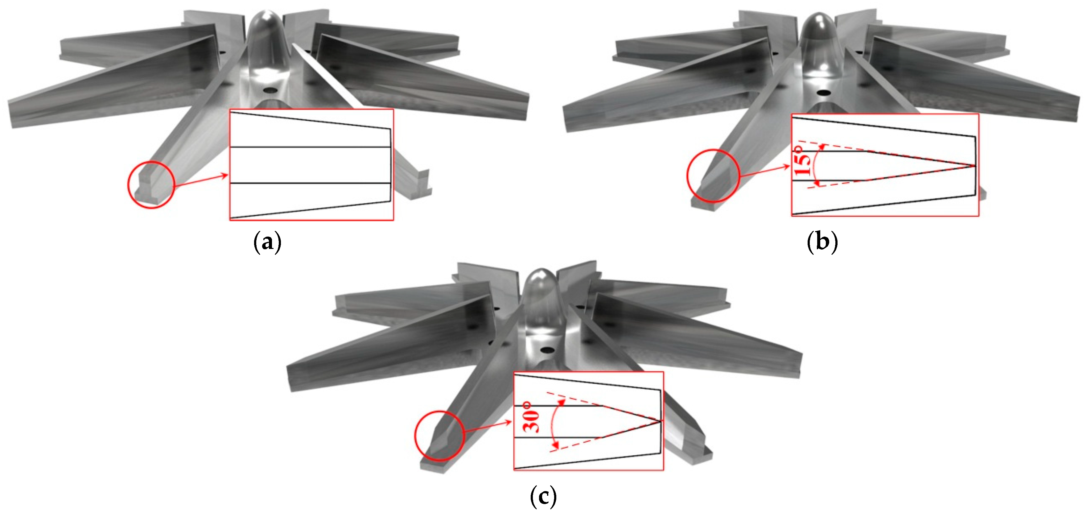
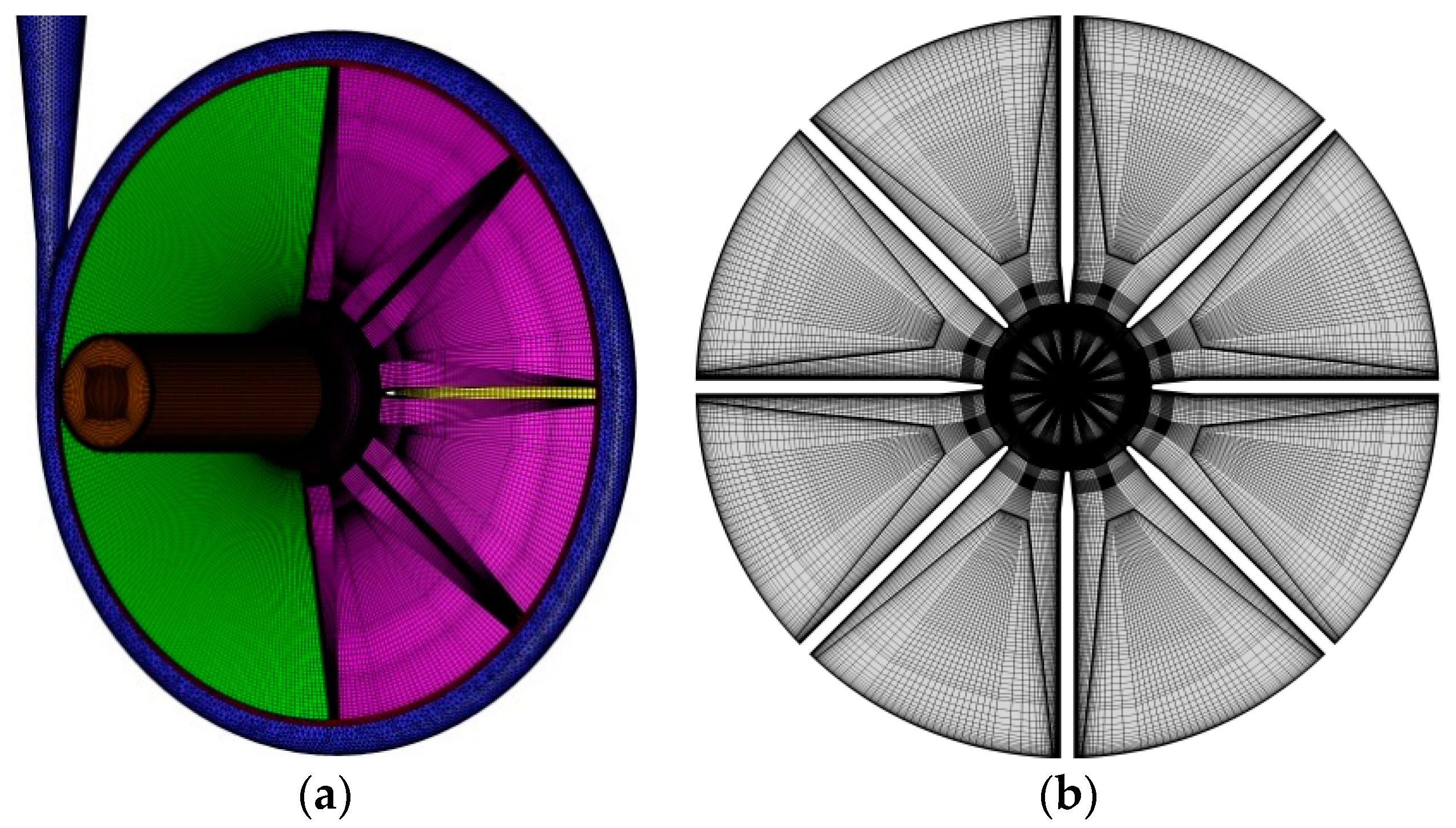
2.1. Geometric Model and Meshing

This study uses a centrifugal pump with low-specific speed ns of 13 as the research object. The rated speed of the pump is 2900 rpm, design flow Qd is 4 m3/h, and design head Hd is 80 m. The main geometric parameters of the centrifugal pump are described as follows: Number of impeller blades Z is 8, pump inlet diameter Ds is 40 mm, pump outlet diameter Do is 32 mm, impeller inlet diameter D1 is 50 mm, impeller outlet diameter D2 is 220 mm, inlet width of blade b1 is 15 mm, and outlet width of blade b2 is 7 mm. Heskestad and Olberts [25] indicated that different blade trailing edge shapes can effectively change the wake structure of the impeller. Blade trailing edge has three types, namely, one-sided arc, two-sided oblique and concave cutting. The effects of different trailing edge shapes on the unstable vortex structure of a single turbine blade outlet in a nonrotating state were experimentally studied. The results show that different cutting angles will have significantly different effects on the unstable vortex structure at the outlet of stationary turbine impeller when the two sides of blade trailing edge are bevelled. This study applies two-sided cutting to the centrifugal pump’s rotating state for studying the effects of different cutting angles of blade trailing edge on the unstable flow inside the centrifugal pump under off-design conditions. This study presents three types of centrifugal pump impeller with different trailing edge cutting cone angles, namely, the original impeller (OTE), where its blade pressure surface and suction surface are bevelled, 15° cutting cone angle of blade trailing edge (OBS15) and 30° cutting cone angle of blade trailing edge (OBS30). Their specific structures are shown in Figure 1.
Figure 2 shows the mesh of full-flow field fluid calculation domain of a centrifugal pump. Structured hexahedral meshes are used in the relatively regular fluid domains, such as the inlet section, impeller and tip clearance. Complicated calculation domains, such as the volute, use an unstructured mesh. In particular, an unstructured hexahedral core mesh is used in the main area of the volute calculation domain except the near-wall area, and the near-wall area of the volute is encrypted using a prism layer. Considering the influence of wall y+ value on the accuracy of shear stress transport (SST) k-ω turbulence model and LES numerical calculation, boundary layer encryption is performed on each wall surface of the impeller. Grid-independent verification is conducted on the performance of the original pump. For different grid numbers (0.54 × 10⁶, 2.35 × 10⁶, 4.11 × 10⁶, 6.27 × 10⁶, 8.39 × 10⁶, 10.42 × 10⁶), head coefficients ψ are 1.494, 1.458, 1.418, 1.417, 1.419 and 1.420, respectively. The performance of the centrifugal pump is basically stable when the number of grids in the flow field calculation domain exceeds 2.35 × 10⁶. Considering the influence of the number of grids on performance and y+ value, the total number of grids in the flow field calculation domain is set to 10.42 × 10⁶, the number of grids of the impeller is set to 7.38 × 10⁶, and the average y+ value of the pump surface is 10.53. The average y+ value of impeller is 5.13.

2.2. Numerical Simulation Method

Numerical simulation calculations on the fluid calculation domain of the centrifugal pump are conducted on Fluent 16.0 software. The LES turbulence model is used for transient simulation because it can accurately capture the vortex removal from the blade trailing edge. The results of steady-state calculations of the SST k-ω turbulence model are used to compare and analyse the performance of centrifugal pumps with different blade trailing edges [21,26]. The calculation medium is water, where density ρ = 998.2 kg/m3, and dynamic viscosity μ = 0.001006 Pa·s. Velocity inlets are used as the boundary conditions at the inlet, and outflows are used as the boundary conditions at the outlet. The time step in the unsteady calculation of the full flow field is based on a time step of each time the impeller rotates through 1° and a rotation period of 360-time steps. The speed of the centrifugal pump model used in this study is 2900 r/min, and the time step is 0.000057471 s. The convergence residual accuracy of each physical quantity in the calculation is set to 10−5.

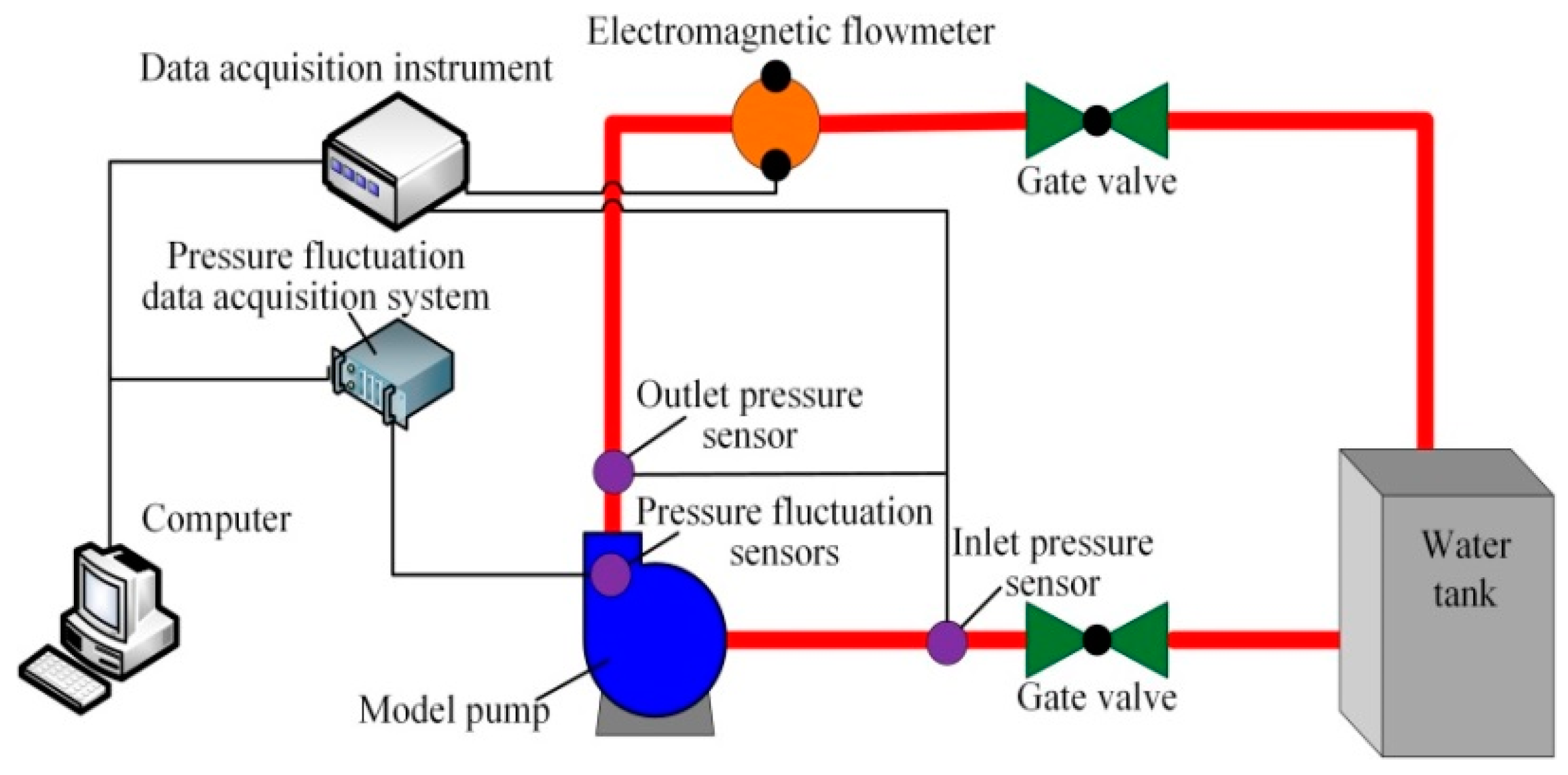
3. Experimental Setup and Method

Figure 3 shows the setup of the experimental bench system. The experimental system mainly includes a centrifugal pump, a water tank, an electromagnetic flowmeter, a control valve, a static pressure sensor, data acquisition system and an analysis system. The working range of the selected electromagnetic flowmeter is 0–30 m3/h, and the measurement error of the flowmeter is 0.5%. The measurement range of the pressure sensor used in the experiment is 0–2 MPa, and the measurement error is less than 0.5%.
Figure 4 shows a comparison of the experimental and simulated performance results of the original pump. The numerical simulation results in Figure 4 are the steady-state calculation results using the SST k-ω turbulence model. In the simulation of the Q-ψ curve, the maximum error between the numerical simulation and experimental results is 5%. Under part-load condition 0.2Qd and overload condition 1.4Qd, the errors between the numerical simulation and experimental results are 4.5% and 4.4%, respectively. In the simulation of the Q-η curve, the error between the numerical simulation and experimental results is less than 3%. Under part-load condition 0.2Qd and overload condition 1.4Qd, the errors between the simulation and experimental results are 0.2% and 1.4%, respectively. The numerical calculation results are consistent with the experimental results, indicating that the numerical calculation method used in this study has high reliability and accuracy.

4. Results and Discussion

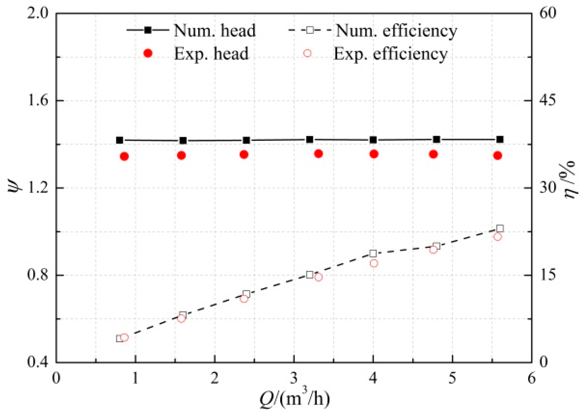
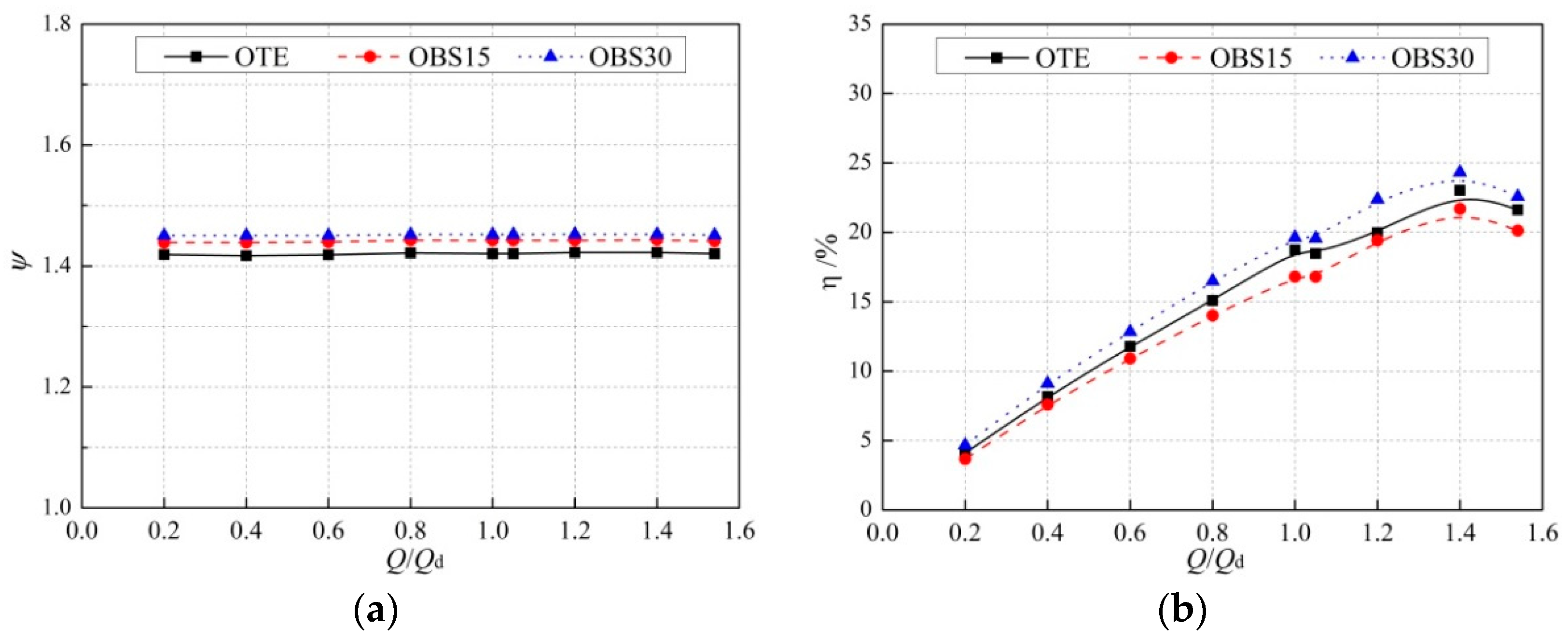
4.1. Performance Analysis

As shown in Figure 5, the performance of centrifugal pumps with different trailing edges of blade are analysed and compared on the basis of the steady-state calculation results using the SST k-ω turbulence model. As shown in Figure 5a, the head coefficient of the pump is improved using the OBS15 and OBS30 impellers under different flow rates. With a small flow rate of 0.2Qd, the head coefficients of OBS15 and OBS30 impellers increase by 0.02 and 0.04 compared with the OTE pump. Under the large flow of 1.4Qd, the head coefficients of OBS15 and OBS30 schemes increase by 0.02 and 0.03 compared with the OTE impeller. As shown in Figure 5b, the improvement of pump efficiency is better when the cutting angle of blade trailing edge is 30° (OBS30) compared with the OTE impeller. With a small flow rate of 0.2Qd, the OBS30 impeller increases its efficiency by 0.6% compared with the OTE impeller. Under large flow of 1.4Qd, the OBS30 impeller increases its efficiency by 1% compared with the OTE impeller. The efficiency of the OBS15 impeller significantly decreases.

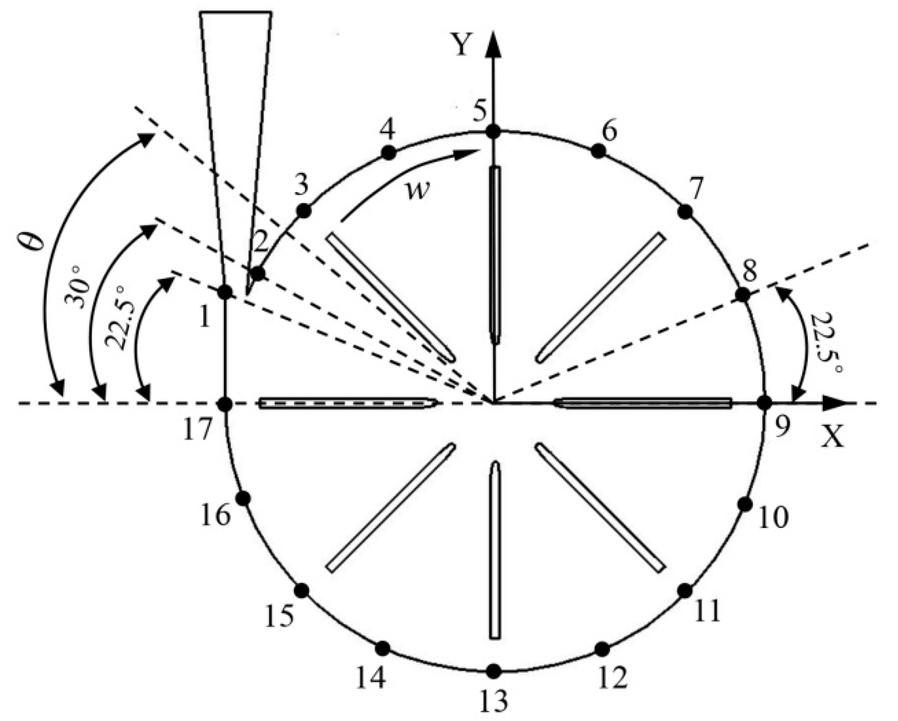
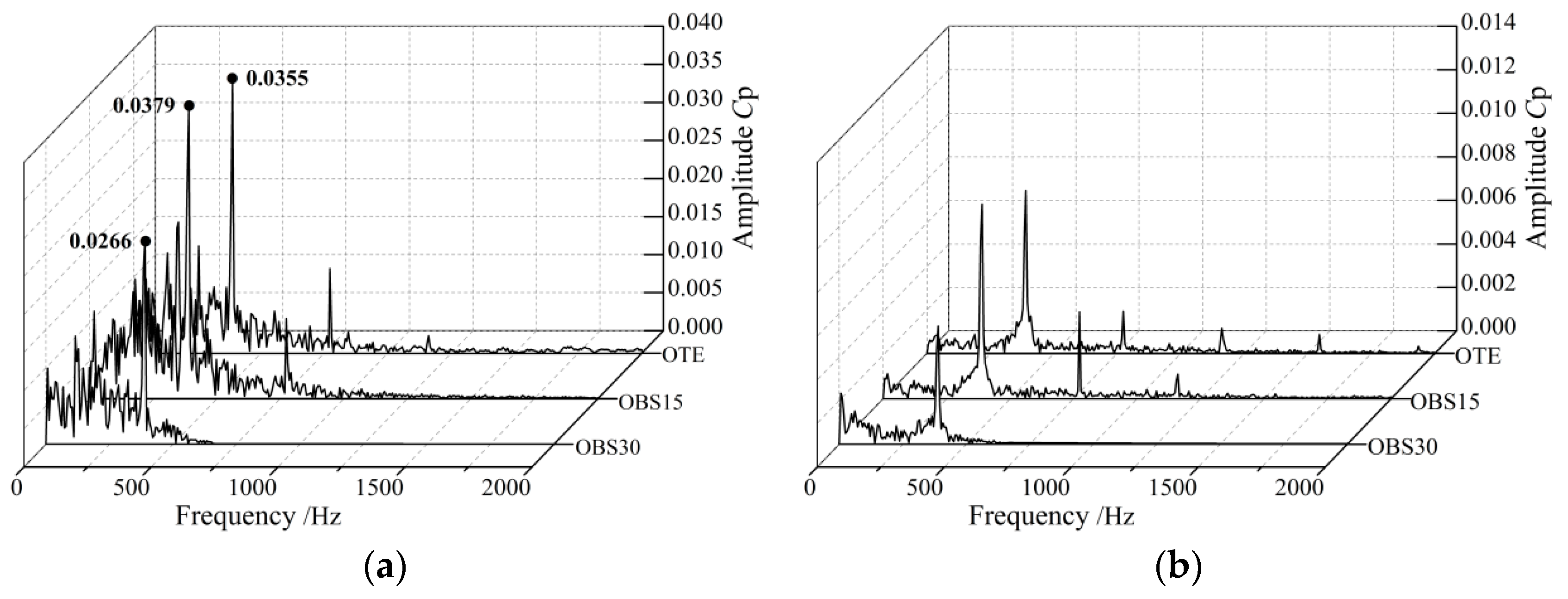
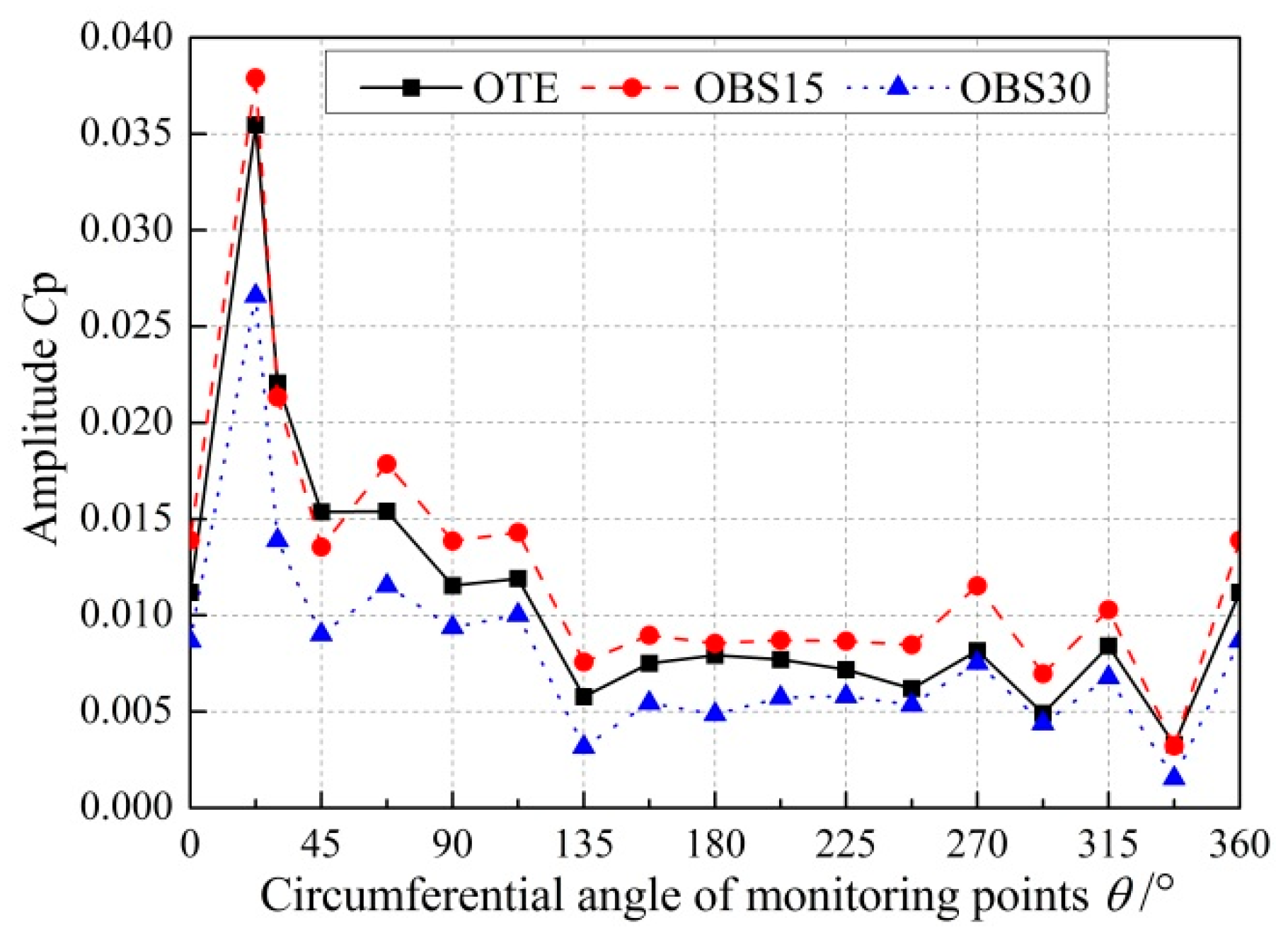
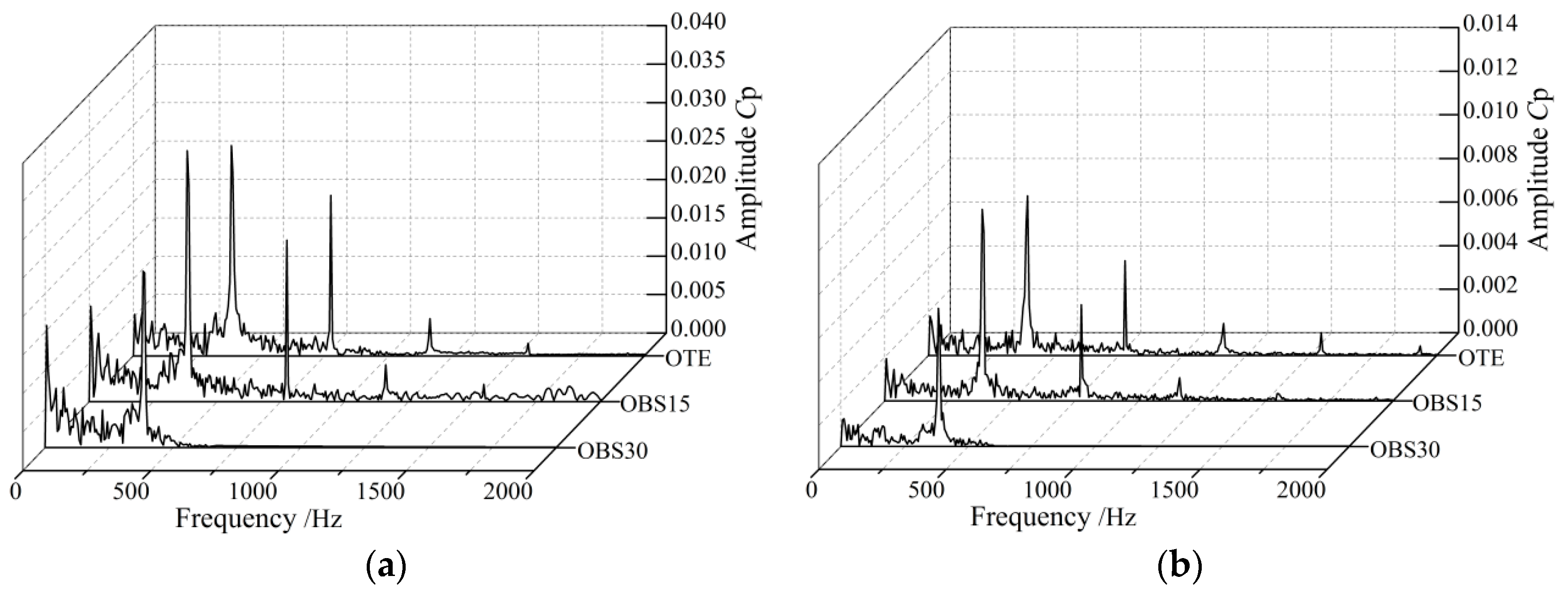
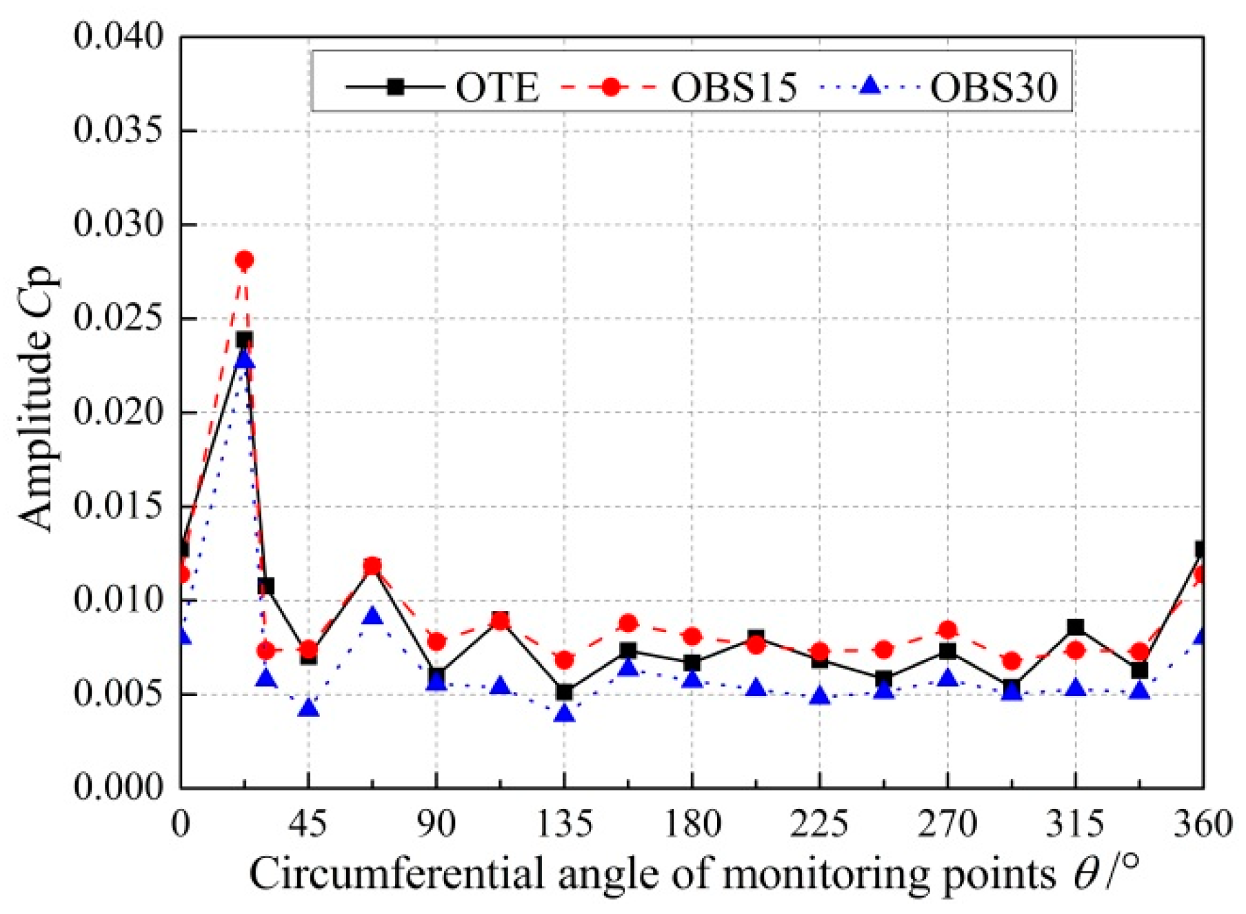
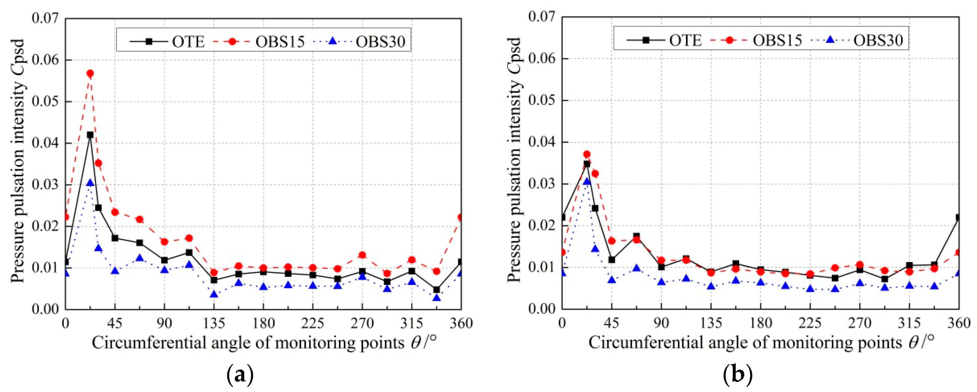
4.2. Analysis of Unstable Pressure Pulsations

Figure 6 shows the layout of the pressure pulsation monitoring points SP1–SP17 in the numerical simulation. As shown in Figure 6, 17 monitoring points are set in the circumferential direction of the volute. Except for monitoring point SP2, the two adjacent monitoring points differ by 22.5°. Monitoring point SP2 is set at an angle of 30° between the tongue and the negative direction of the x axis. Dimensionless coefficient Cp of pressure is used to study the pressure pulsation of centrifugal pumps with different blade trailing edges. The specific formula of static pressure coefficient Cp is expressed as follows [21]:
C p = p p ¯ 0.5 ρ u 2 2
where p represents the static pressure value of each monitoring point, p ¯ represents the average static pressure value of each monitoring point in one rotation period, ρ represents the density of the fluid medium, and u2 represents the peripheral velocity of the impeller outlet.
Figure 7 shows that pressure pulsation monitoring point SP1 is near the tongue area, and pressure pulsation monitoring point SP8 is far from the tongue area of the centrifugal pump with different blade trailing edges under part-load condition 0.2Qd. As shown in Figure 7a, the frequency domain amplitudes of the centrifugal pump with different trailing edge blades are mainly concentrated in the low-frequency region of monitoring point SP1 near the tongue region. The main frequency is near the blade passing frequency fBPF. In addition to the main frequency, the other low-frequency regions have large amplitudes, which could be caused by the recirculation and unstable vortex structure at SP1 under part-load condition 0.2Qd. The main frequency amplitude of the OBS30 impeller is smaller than that of the original OTE impeller, and its value is 0.0266. The OBS15 impeller’s main frequency amplitude is greater than that of the OTE impeller, and its value is 0.0379. As shown in Figure 7b, the frequency domain amplitudes of the centrifugal pump with different trailing edge blades are mainly concentrated at the blade passing frequency, their high harmonic frequencies are located at monitoring point SP8 far from the tongue, and the amplitude of the remaining low frequency regions is small. The main frequency amplitude of the OBS30 impeller is smaller than that of the OTE impeller, and the reduction value is 0.0021. This condition indicates that an improvement is observed on the pressure pulsation of the near tongue and far from tongue areas when the cutting angle of blade trailing edge is 30° under part-load condition.
Figure 8 shows the main frequency amplitude of pressure pulsation at the different impellers under part-load condition 0.2Qd. The ordinate is the main frequency amplitude of each monitoring point, and the abscissa is the angle between each monitoring point in the volute circumferential direction that is in the negative direction of the x axis. As shown in Figure 8, the main frequency amplitude of the region near the tongue (22.5° to 112.5°) of the centrifugal pump with different blade trailing edges is larger than that of the region far from the tongue. The main frequency amplitude of each monitoring point of the OBS30 impeller is smaller than that of the OTE impeller. The main frequency amplitude of the OBS15 impeller is greater than that of the OTE impeller. Table 1 shows the reduction rate of blade trailing edge to the average main frequency amplitude of the centrifugal pump under part-load condition 0.2Qd. The calculation formula is expressed as [26]:
C ¯ p - n = i = 1 n C p n n ( n = 17 )
where Cp−n represents the the static pressure coefficient amplitude of the 17 monitoring points at main frequency fBPF. The expression of the main frequency amplitude reduction rate is expressed as follows [26]:
A d = C p ¯ - OTE C p ¯ - n C p ¯ - OTE × /
where C p ¯ - OTE is the magnitude of the average static pressure coefficient of the original impeller (OTE) at fBPF, and C p ¯ - n represents the average static pressure coefficient amplitude of different impellers. The OBS30 impeller reduces the average main frequency amplitude of pressure pulsation of the centrifugal pump, and the reduction rate is 13.04%.
Figure 9 shows the frequency distributions of pressure pulsation monitoring points SP1 and SP8 under overload condition 1.4Qd. As shown in Figure 9, the main frequencies of pressure pulsation at monitoring point SP1 near the tongue area and pressure pulsation monitoring point SP8 far from the tongue area of the centrifugal pump with different blade edges are near the blade passing frequency fBPF. The frequency domain amplitude is mainly concentrated at the blade passing frequency and its high harmonic frequency. The main frequency amplitudes of different impellers at SP1 near the tongue region are larger than that at SP8 far from the tongue region. At different monitoring points, the main frequency amplitude of the OBS30 impeller is smaller than that of the OTE impeller, the reduction at tongue SP1 is larger, and the reduction value is 0.0234. This condition indicates that the 30° cutting angle of blade trailing edge improves the pressure pulsation at the near tongue and far from tongue areas under overload condition.
Figure 10 show the main frequency amplitude of pressure pulsation at the different impellers under overload condition 1.4Qd. As shown in Figure 10, the near tongue region has a large main frequency amplitude ranging from 22.5° to 67.5° under overload condition, which is smaller than the region (22.5° to 112.5°) under part-load condition. This condition is because the unstable flow structure at the tongue and the unstable vortex area at the tongue gradually decrease with the increase in flow rate. The OBS30 impeller reduces the main frequency amplitude of pressure pulsation. Under overload condition, the main frequency amplitude of the OBS15 impeller remains large. Table 2 shows the reduction rates of the blade trailing edge to the average main frequency amplitude of the centrifugal pump under overload condition 1.4Qd. As shown in Table 2, the OBS30 impeller reduces the average main frequency amplitude of circumferential pressure pulsation of the centrifugal pump, and the reduction rate is 13.556%. The OBS15 impeller increases the average main frequency amplitude of pressure pulsation, with a reduction rate of −6.83%, and its deterioration rate is slightly smaller than that under part-load condition. The reduction effect of the OBS30 impeller on the main frequency amplitude is unaffected by flow rate on the basis of the reduction rate of the main frequency amplitude under off-design conditions obtained in Table 1 and Table 2. The OBS15 impeller is immensely affected by flow rate and has the most obvious effect on pressure pulsation reduction among the three impellers under part-load condition.
No pressure fluctuation component of instantaneous fluctuation is obtained because the pressure pulsation component obtained through transient simulation is only a phase average value. To obtain the relationship between pressure pulsation intensity and flow rate at different positions in the circumferential direction of the volute in a rotation period, the dimensionless coefficient of time-dependent pressure pulsation intensity is defined as Cpsd and is expressed is [27]:
C psd = 1 N i = 0 N 1 ( p ( x , y , z , t i ) 1 N i = 1 N p ( x , y , z , t i ) ) 2 1 2 ρ u 2 2 = 1 N i = 0 N 1 ( p p ¯ ) 2 1 2 ρ u 2 2
where N is the number of time steps in a stable rotation period (360 in this article), p(x, y, z, ti) is the static pressure value of node (x, y, z) at the ith time step. Figure 11 shows the distribution of pressure pulsation intensity coefficient Cpsd in the circumferential direction of the centrifugal pump with different impellers at 0.2Qd and 1.4Qd. As shown in Figure 11, the Cpsd value of the centrifugal pump with the OBS30 impeller is smaller than that of the OTE impeller under part-load condition 0.2Qd and overload condition 1.4Qd. Under off-design conditions, pressure pulsation intensity Cpsd in the circumferential direction of the volute has a significant reduction effect when the cutting angle of blade trailing edge is 30°. The pressure pulsation intensity of the region (22.5° to 112.5°) is larger than that of the region (112.5° to 360°) under different schemes. The closer it is to the tongue, the greater the pressure pulsation intensity Cpsd will be. The pressure pulsation intensity in the circumferential direction of the centrifugal pump with different impellers decreases with the increase in flow rate, and the decreasing trend of the tongue area (22.5° to 112.5°) is obvious. In the tongue area, the OBS15 impeller is immensely affected by flow rate. The Cpsd value of the OBS15 impeller in the tongue region is the largest among the impellers under part-load condition. This finding indicates that the internal flow of the OBS15 impeller is unstable under part-load condition.

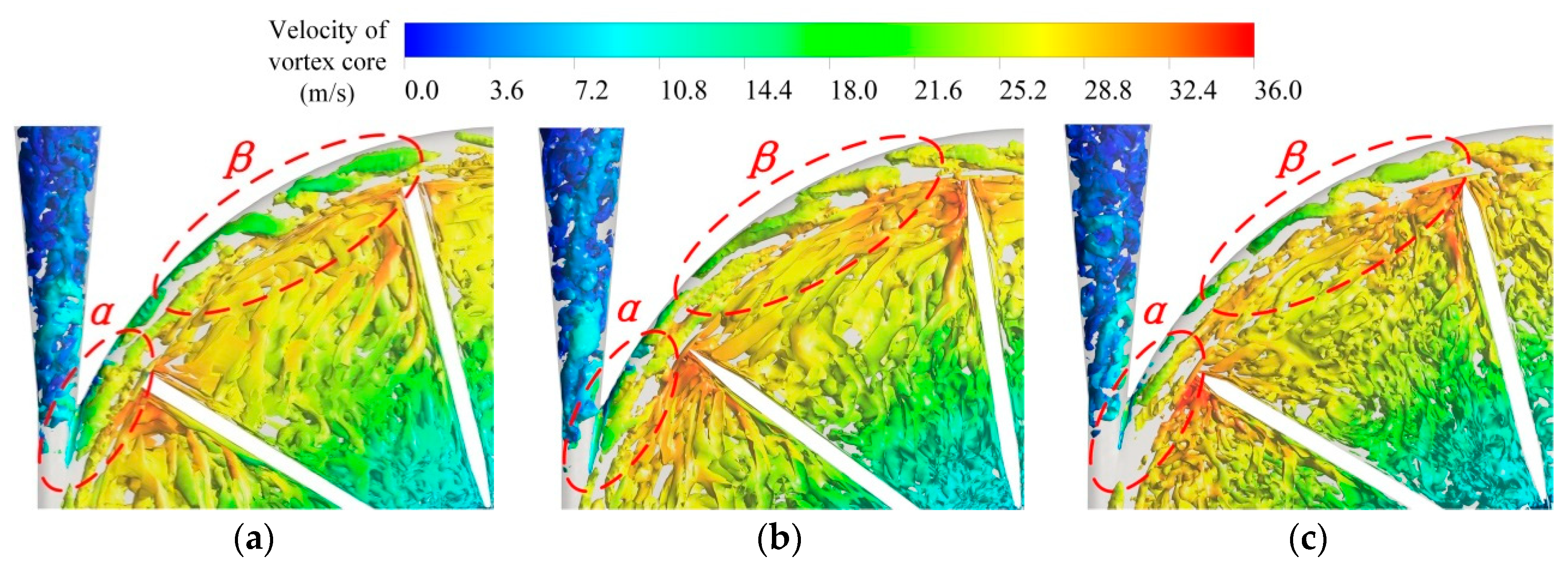
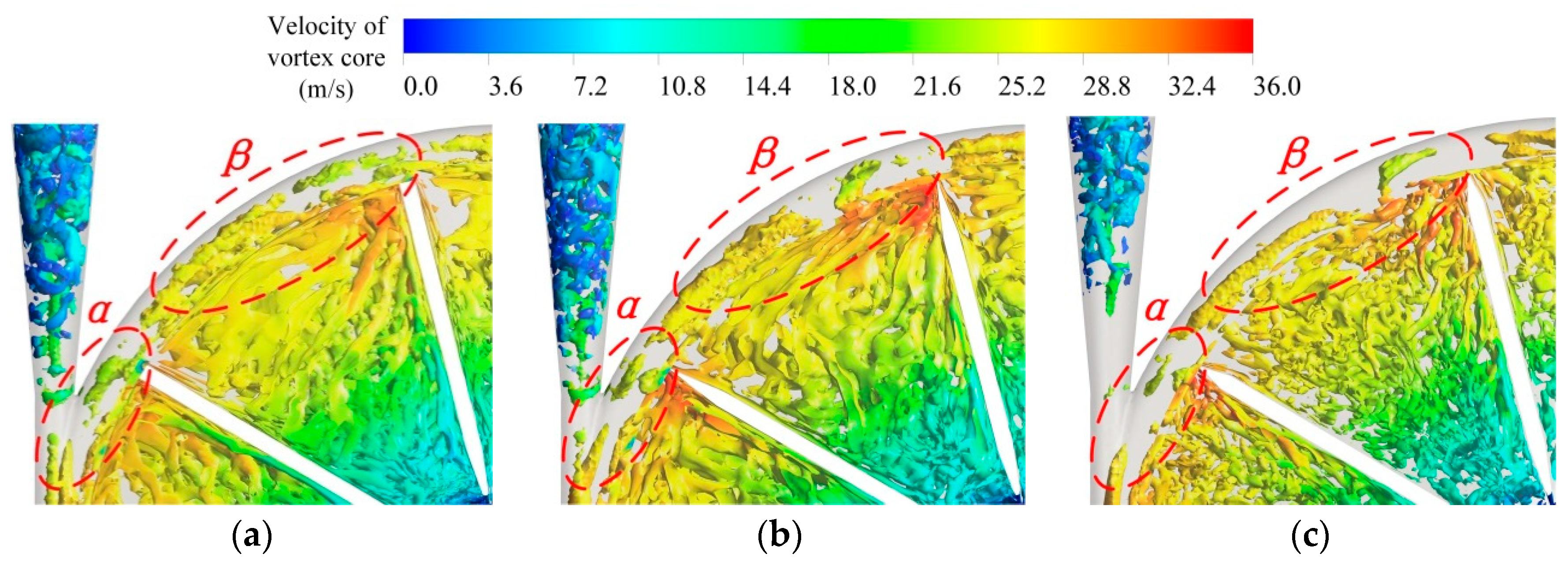
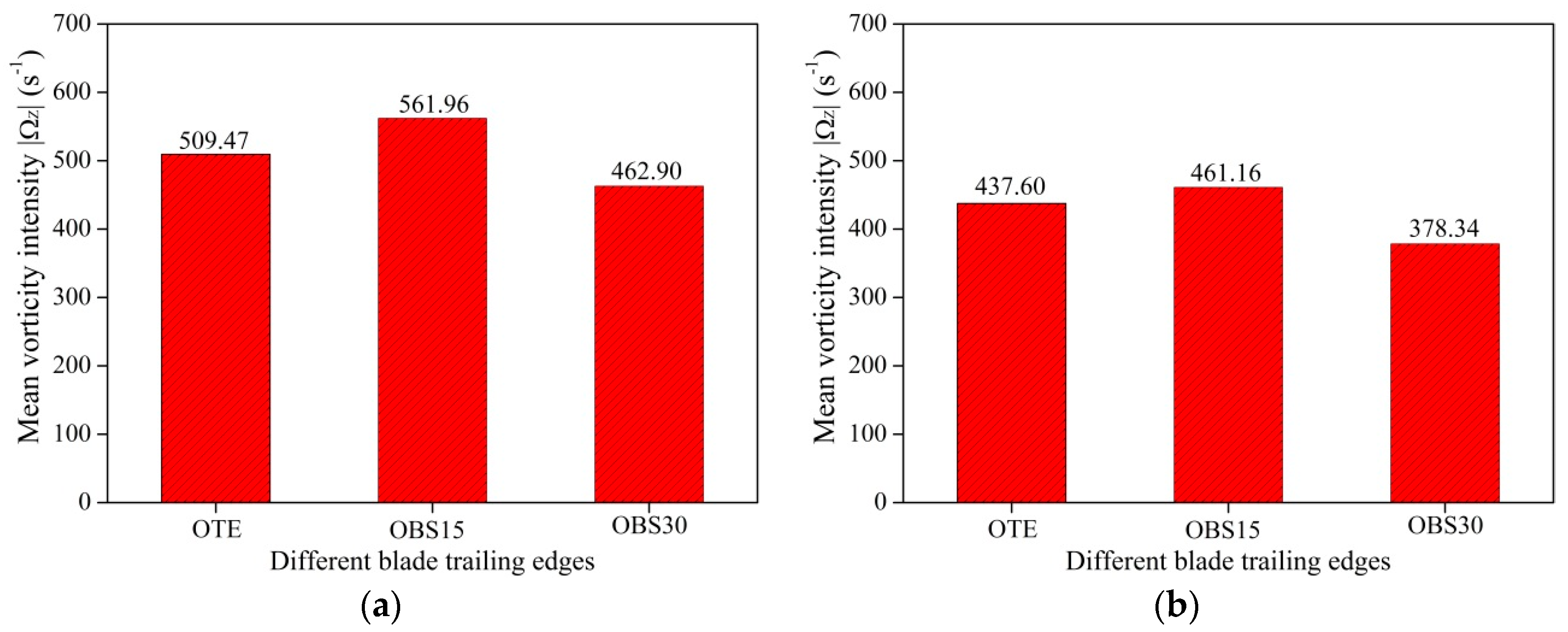
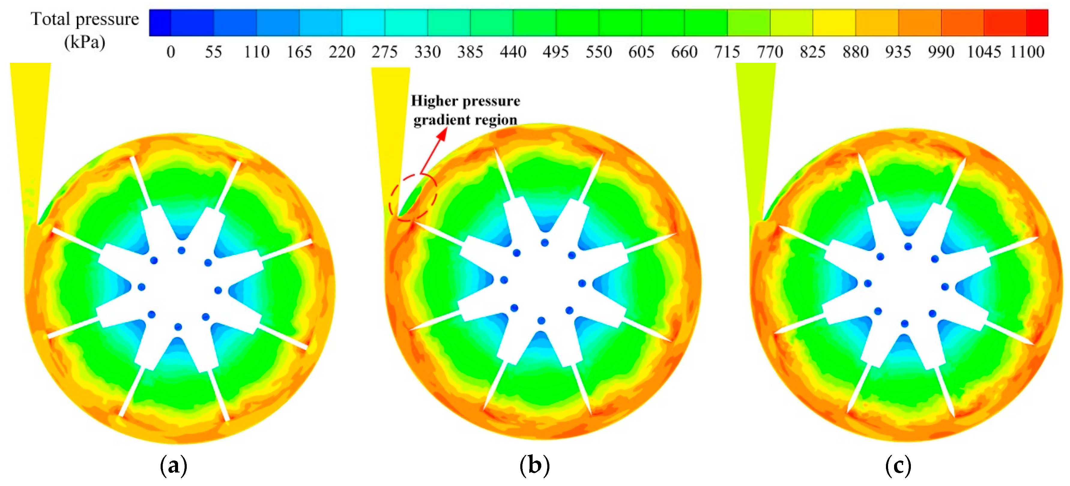
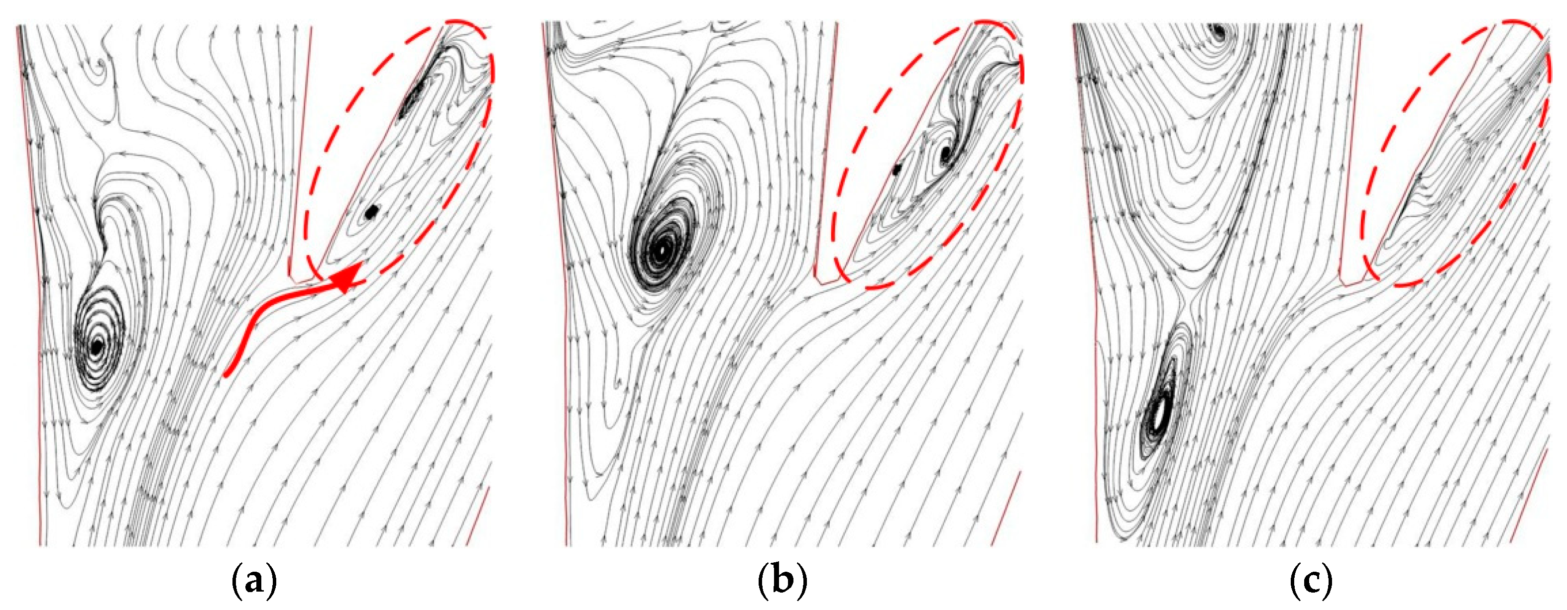
4.3. Analysis of Unstable Flow Structure

As a common unstable vortex structure, the trailing shedding vortex at the impeller outlet affects the internal flow of the centrifugal pump and is closely related to the unsteady pressure pulsation of the centrifugal pump [26,28]. At present, vorticity, Q-criterion, and new Ω methods are widely used as the main vortex identification tools in hydraulic machines, such as centrifugal pumps [29,30,31]. The vorticity method cannot distinguish the shear and actual rotational motions of the vortex, thereby affecting the accuracy of the results. The Q-criterion method is ineffective in identifying surface vortices near the wall and in areas with high velocity gradients. Therefore, the new Ω method is used to identify the trailing shedding vortices at the impeller outlet, which can be expressed as [32]:
Ω = ( × V R ) 2 × V 2 2 R 2 2
where R is the vorticity, and Ω is the ratio of the vortex amount to the total vorticity. The value of Ω isosurface selected in this analysis is 0.52 [32]. This study analyses the transient wake vortex distribution of each centrifugal pump when the blade passes the tongue. Figure 12 shows the shedding vortex distribution at the impeller outlet with different cutting schemes under part-load condition 0.2Qd. As shown in Figure 12, α and β, which are two main trailing shedding vortex regions, appear in the rotor–stator interaction regions of the impeller and the volute. In the α region close to the tongue, the OTE and OBS15 impellers have a large area of shedding vortex regions. The large area of the vortex structure occupies the entire area of the tongue, indicating that many severe shedding vortices and considerable tongue impacts occur in the OTE and OBS15 impellers. Compared with the large area shedding vortices of the OTE impeller in the α and β regions, the shedding vortex area of the OBS30 impeller is significantly reduced, and no obvious vortex structure appears at the tongue. This condition indicates that the blade with a 30° cutting angle at the trailing edge has good suppression effect on the shedding vortex generation of the pump under part-load condition 0.2Qd.
Figure 13 shows the shedding vortex distribution at the impeller outlet with different cutting schemes under over-load condition 1.4Qd. As shown in Figure 13, the OTE and OBS15 impellers have a large area of shedding vortex regions in the α region. The shedding vortex area in the OBS30 impeller is smaller than that of the OTE impeller. As shown in Figure 12 and Figure 13, different cutting angles of blade trailing edge have different effects on the impeller outlet shedding vortex under different flow rates. The OBS30 impeller has a significant impact on the shedding vortex distribution at the impeller outlet and improves the flow structure at the impeller outlet.
In recent years, scholars have applied axial vorticity analysis to quantitatively study the influences of blade trailing edge on the flow characteristics of centrifugal pumps and proved that the intensity of axial vorticity is closely related to the flow structure [28]. Therefore, this study analyses the axial vorticity in the impeller outlet and quantitatively compares the effects of blade trailing edge on unsteady flow in a centrifugal pump. The calculation formula is expressed as [28]:
Ω Z = v y x v x y
Figure 14 shows the comparison of average vorticity intensity at the blade trailing edge of different schemes at part-load condition 0.2Qd and overload condition 1.4Qd. At different flow rates, the average vorticity intensity at the blade trailing edge of OBS30 is less than that of the average vortex intensity of OTE, and the average vorticity intensity of OBS15 is greater than the average vortex intensity of OTE. At 0.2Qd, the average vorticity intensity of the OBS15 scheme is 561.96 s−1. The average vorticity intensity of the OBS30 scheme is 462.90 s−1. Compared with the original impeller OTE, the average vortex intensity at the blade trailing edge of the OBS30 scheme is reduced by 46.57 s−1. At 1.4Qd, the value of the OBS30 impeller is 378.34 s−1, and the value of the OBS15 impeller is 461.16 s−1. These results show that OBS30 can improve the flow structure of blade trailing edge of the centrifugal pump at 0.2Qd and 1.4Qd.
Figure 15 shows the transient total pressure distribution in the midsection of the centrifugal pump with different impellers when the blades are in the tongue-separating position under part-load condition 0.2Qd. As shown in Figure 15, a low-pressure area appears at the tongue of the centrifugal pump and forms a large pressure gradient with the adjacent high-pressure area of the blade trailing edge. The low-pressure area at the tongue of the OBS15 impeller is significantly larger than that of the OTE impeller. The central pressures in the low-pressure region at the tongue of the OTE, OBS15 and OBS30 are 510, 495 and 660 kPa, respectively. The central pressures in the high-pressure region at the blade trailing edge of the OTE, OBS15 and OBS30 are 935, 990 and 1045 kPa, respectively. The pressure difference at the tongue of the OBS30 impeller is slightly smaller than that at the OTE impeller, and the reduction value is 40 kPa. The pressure distribution in the area far from the tongue is uniform, indicating that the internal flow of the pump is stable in other areas. The large pressure difference in the tongue region will lead to a large pressure gradient region, thereby resulting in the generation of an unstable flow structure in this region.
Figure 16 shows the relative velocity streamline distribution at the tongues of the centrifugal pump with different impellers when the blades are in the tongue-separating position at 0.2Qd flow rate. As shown in Figure 16, different degrees of backflow and vortex flow occur at the high-pressure gradient regions of the septum tongue of centrifugal pump with different blade trailing edges. Two unstable vortex structures appear at the tongue of the OTE impeller, and a certain distance is observed between the two vortex cores. Two vortex structures also appear at the tongue of the OBS15 impeller, where the area of the unstable vortex structure is larger than that of the OTE impeller, and the distance between the two vortex cores is short. The unstable vortex structure at the tongue of OBS30 impeller is weaker than that of the OTE impeller, and no obvious vortex core structure appears. This condition indicates that the OBS30 impeller has a certain improvement on the unstable vortex structure caused by backflow at the centrifugal pump tongue, thereby resulting in a significant decrease in the intensity of unstable pressure pulsations at the tongue.
As shown in Figure 17, the total pressure distribution in the cross-section of the centrifugal pump with different blade trailing edges is distributed at 1.4Qd. As shown in Figure 17, the centrifugal pump with different blade trailing edges has many unstable pressure areas at the volute outlet, and low-pressure areas appear in the wall area near the volute outlet. A high-pressure region exists in the middle flow channel of the volute outlet. The centre pressures of the low-pressure area in volute outlet with different schemes (OTE, OBS15 and OBS30) are 585, 580 and 780 kPa, respectively. The central pressures of the high-pressure area with different schemes (OTE, OBS15 and OBS30) are 975, 990 and 1020 kPa. Therefore, a large pressure gradient region is generated between adjacent high- and low-pressure regions at the volute outlet, thereby resulting in the generation of backflow and unstable vortex structures.

5. Conclusions

In this study, a straight-blade centrifugal pump was used as the research object. The influences of the cutting cone angle of blade trailing edge on unstable pressure pulsation and unstable flow structure were studied in the centrifugal pump under off-design conditions through LES.
The research results indicate that the pressure gradient at the tongue of the OBS30 impeller is lower than that of the OTE impeller, and the OBS15 impeller is higher than that of the OTE impeller under part-load conditions. These results show that the OBS30 impeller can effectively improve the unstable vortex structure caused by backflow at the centrifugal pump tongue. This phenomenon makes the performance of the pump with the OBS30 impeller higher than that of the original pump, whereas the efficiency of the OBS15 impeller is lower than that of the original pump. The OBS30 impeller reduces the main frequency amplitude and pressure pulsation intensity of the volute pressure pulsation. The OBS15 impeller has the opposite effect because of the increase in wake vortex intensity. Under the overload condition, the reduction in the main frequency amplitude of pressure pulsation by the OBS30 impeller is similar to that under the part-load condition. The OBS30 impeller can improve the unstable flow phenomenon in the centrifugal pump under off-design conditions. This research serves as reference in effectively suppressing the unstable flow in centrifugal pumps and improving their safety and stability. The results provide insight into the optimisation of the blade trailing edge profile.

Author Contributions

Conceptualization, B.C.; formal analysis, Z.Z.; experiment investigation, C.Z., B.C. and Y.Z.; writing—original draft preparation, C.Z.; editing, Y.Z. All authors have read and agreed to the published version of the manuscript.

Funding

This research was funded by the Joint Project from National Natural Science Foundation of China and Liaoning Province, grant No. U1608258, the National Natural Science Foundation of China, grant No. 51579225 and Zhejiang Provincial Natural Science Foundation of China, grant number LZ20E060002.

Conflicts of Interest

The authors declare no conflict of interest.

Nomenclature

Qddesign flow rate [m3/h]
Hhead [m]
Hddesign head [m]
Zblade number
Dspump inlet diameter [mm]
Dopump outlet diameter [mm]
D1impeller inlet diameter [mm]
D2impeller outlet diameter [mm]
b1inlet width of blade [mm]
b2outlet width of blade [mm]
ψhead coefficient [2Hg/u22]
ρfluid density [kg/m3]
μeddy viscosity [Pa s]
fBPFblade-passing frequency [Hz]
Cpnon-dimensional static pressure coefficient
u2peripheral speed of the impeller outlet [m/s]
Adreduction rate of main frequency amplitude
Cpsdnon-dimensional coefficient of pressure pulsation intensity
Rvorticity
Ωratio of vorticity to total vorticity
Ωzaxial vorticity

References

  1. Shankar, A.; Subramaniam, U.; Shanmugam, P.; Hanigovszki, N. A comprehensive review on energy efficiency enhancement initiatives in centrifugal pumping system. Appl. Energy 2016, 181, 495–513. [Google Scholar] [CrossRef]
  2. Posa, A.; Lippolis, A.; Balaras, E. Large-eddy simulation of a mixed-flow pump at off-design conditions. ASME J. Fluids Eng. 2015, 137, 101302. [Google Scholar] [CrossRef]
  3. Cheah, K.W.; Lee, T.S.; Winoto, S.H.; Zhao, Z.M. Numerical flow simulation in a centrifugal pump at design and off-design conditions. Int. J. Rotating Mach 2007, 2007, 83641. [Google Scholar] [CrossRef]
  4. Binama, M.; Su, W.; Cai, W.H. Blade trailing edge position influencing pump as turbine PAT pressure field under part-load conditions. Renew Energy 2019, 136, 33–47. [Google Scholar] [CrossRef]
  5. Si, Q.; Yuan, S.; Yuan, J.; Liang, Y. Investigation on flow-induced noise due to backflow in low specific speed centrifugal pumps. Adv. Mech. Eng. 2013, 2013, 109048. [Google Scholar] [CrossRef]
  6. Fu, Y.; Yuan, J.; Yuan, S.; Pace, G.; Agostino, L.; Huang, P.; Li, X. Numerical and experimental analysis of flow phenomena in a centrifugal pump operating under low flow rates. ASME J. Fluids Eng. 2015, 137, 011102. [Google Scholar] [CrossRef]
  7. Zhang, N.; Yang, M.; Gao, B. Investigation of rotor-stator interaction and flow unsteadiness in a low specific speed centrifugal pump. Stroj. Vestn. J. Mech. Eng. 2015, 62, 21–31. [Google Scholar] [CrossRef]
  8. Jia, X.Q.; Zhu, Z.C.; Yu, X.L. Internal unsteady flow characteristics of centrifugal pump based on entropy generation rate and vibration energy. Proc. Inst. Mech. Eng. Part E J. Process Mech. Eng. 2018, 23, 456–473. [Google Scholar] [CrossRef]
  9. Tao, J.Y.; Lin, Z.; Ma, C.J. An experimental and numerical study of regulating performance and flow loss in a v-port ball valve. ASME J. Fluids Eng. 2020, 142. [Google Scholar] [CrossRef]
  10. Ji, B.; Long, Y.; Long, X. Large eddy simulation of turbulent attached cavitating flow with special emphasis on large scale structures of the hydrofoil wake and turbulence-cavitation interactions. J. Hydrodyn. 2017, 29, 27–39. [Google Scholar] [CrossRef]
  11. Furukawa, A.; Takahara, H.; Nakagawa, T. Pressure fluctuation in a vaned diffuser downstream from a centrifugal pump impeller. Int. J. Rotating Mach. 2003, 9, 285–292. [Google Scholar] [CrossRef] [Green Version]
  12. Gao, B.; Guo, P.; Zhang, N. Unsteady pressure pulsation measurements and analysis of a low specific speed centrifugal pump. ASME J. Fluids Eng. 2017, 139, 071101. [Google Scholar] [CrossRef]
  13. Yan, P.; Chu, N.; Wu, D. Computational fluid dynamics-based pump redesign to improve efficiency and decrease unsteady radial forces. ASME J. Fluids Eng. 2016, 139, 011101. [Google Scholar] [CrossRef]
  14. Zhang, N.; Yang, M.; Gao, B. Experimental and numerical analysis of unsteady pressure pulsation in a centrifugal pump with slope volute. J. Mech. Sci. Technol. 2015, 29, 4231–4238. [Google Scholar] [CrossRef]
  15. Choi, J.S.; Mclaughlin, D.K.; Thompson, D.E. Experiments on the unsteady flow field and noise generation in a centrifugal pump impeller. J. Sound Vib. 2003, 263, 493–514. [Google Scholar] [CrossRef]
  16. Ding, H.; Li, Z.; Gong, X. The influence of blade outlet angle on the performance of centrifugal pump with high specific speed. Vacuum 2019, 159, 239–246. [Google Scholar] [CrossRef]
  17. Zhang, J.F.; Zhang, X.; Xie, L.H. Study on the influence of blade outlet angle on unsteady flow and structural dynamic characteristics for chemical process pump. IOP Conf. Ser. EES 2018, 163, 012047. [Google Scholar] [CrossRef]
  18. Zhang, J.F.; Li, G.D.; Mao, J.Y. Effects of the outlet position of splitter blade on the flow characteristics in low-specific-speed centrifugal pump. Adv. Mech. Eng. 2018, 10, 1–12. [Google Scholar] [CrossRef]
  19. Al-Qutub, A.M.; Khalifa, A.E.; Al-Sulaiman, F.A. Exploring the effect of V-shaped cut at blade outlet of a double volute centrifugal pump. J. Press. Vessel Technol. ASME 2012, 134, 021301–021309. [Google Scholar] [CrossRef]
  20. Wu, D.; Yan, P.; Chen, X. Effect of trailing-edge modification of a mixed-flow pump. ASME J. Fluids Eng. 2015, 137, 101205–101214. [Google Scholar] [CrossRef]
  21. Li, B.; Li, X.; Jia, X. The role of blade sinusoidal tubercle trailing edge in a centrifugal pump with low specific speed. Processes 2019, 7, 625. [Google Scholar] [CrossRef] [Green Version]
  22. Luo, Y.; Wen, F.; Wang, S.; Zhang, S.; Wang, S.; Wang, Z. Numerical investigation on the biomimetic trailing edge of a high-subsonic turbine blade. Aerosp. Sci. Technol. 2019, 89, 230–241. [Google Scholar] [CrossRef]
  23. Valipour, P.; Ghasemi, S.E.; Khosravani, M.R.; Ganji, D.D. Theoretical analysis on nonlinear vibration of fluid flow in single-walled carbon nanotube. J. Theor. Phys. 2016, 10, 211–218. [Google Scholar] [CrossRef] [Green Version]
  24. Zobeiri, A.; Ausoni, P.; Avellan, F. How oblique trailing edge of a hydrofoil reduces the vortex-induced vibration. J. Fluid Struct. 2012, 32, 78–89. [Google Scholar] [CrossRef] [Green Version]
  25. Heskestad, G.; Olberts, D.R. Influence of trailing-edge geometry on hydraulic-turbine-blade vibration resulting from vortex excitation. J. Eng. Gas Turbines Power 1960, 82, 103–109. [Google Scholar] [CrossRef]
  26. Gao, B.; Zhang, N.; Li, Z. Influence of the blade trailing edge profile on the performance and unsteady pressure pulsations in a low Specific speed centrifugal pump. ASME J. Fluids Eng. 2016, 138, 051106. [Google Scholar] [CrossRef]
  27. Pei, J.; Yuan, S.; Benra, F.K. Numerical prediction of unsteady pressure field within the whole flow passage of a radial single-blade pump. ASME J. Fluids Eng. 2012, 134, 101103. [Google Scholar] [CrossRef]
  28. Zhang, N.; Liu, X.; Gao, B. Effects of modifying the blade trailing edge profile on unsteady pressure pulsations and flow structures in a centrifugal pump. Int. J. Heat Fluid Flow 2019, 75, 227–238. [Google Scholar] [CrossRef]
  29. Ni, D.; Yang, M.; Gao, B. Numerical study on the effect of the diffuser blade trailing edge profile on flow instability in a nuclear reactor coolant pump. Nucl. Eng. Des. 2017, 322, 92–103. [Google Scholar] [CrossRef]
  30. Ni, D.; Yang, M.; Zhang, N. Unsteady flow structures and pressure pulsations in a nuclear reactor coolant pump with spherical casing. ASME J. Fluids Eng. 2017, 139, 051103. [Google Scholar] [CrossRef]
  31. Yang, B.; Li, B.; Chen, H. Numerical investigation of the clocking effect between inducer and impeller on pressure pulsations in a liquid rocket engine oxygen turbopump. ASME J. Fluids Eng. 2018, 141, 071109. [Google Scholar] [CrossRef]
  32. Liu, C.; Wang, Y.; Yang, Y. New omega vortex identification method. Sci. China Phys. Mech. 2016, 59, 684711. [Google Scholar] [CrossRef]
Figure 1. Geometry of different blade trailing edges: (a) original trailing edge (OTE) impeller; (b) 15° cutting angle of blade trailing edge (OBS15) impeller; (c) 30° cutting angle of blade trailing edge (OBS30) impeller.
Applsci 10 00580 g001
Figure 2. Mesh of computational domain: (a) full flow field of centrifugal pump; (b) impeller.
Applsci 10 00580 g002
Figure 3. Experiment system.
Applsci 10 00580 g003
Figure 4. Numerical and experimental results comparison of the OTE model pump.
Applsci 10 00580 g004
Figure 5. Numerical calculation results comparison of three model pumps: (a) head coefficient; (b) efficiency.
Applsci 10 00580 g005
Figure 6. Numerical simulation of pressure pulsation monitoring points.
Applsci 10 00580 g006
Figure 7. Frequency domain of pressure pulsation for centrifugal pumps with different blade trailing edges under part-load condition (0.2Qd): (a) monitoring point SP1; (b) monitoring point SP8.
Applsci 10 00580 g007
Figure 8. The amplitude of main frequency of pressure pulsation at the different impellers under part-load condition (0.2Qd).
Applsci 10 00580 g008
Figure 9. Frequency domain of pressure pulsation for centrifugal pumps with different blade trailing edges under over-load condition (1.4Qd): (a) monitoring point SP1; (b) monitoring point SP8.
Applsci 10 00580 g009
Figure 10. The amplitude of main frequency of pressure pulsation at the different impellers under over-load condition (1.4Qd).
Applsci 10 00580 g010
Figure 11. Pressure pulsation intensity distribution in the circumferential direction of volute: (a) part-load condition (0.2Qd); (b) over-load condition (1.4Qd).
Applsci 10 00580 g011
Figure 12. Shedding vortex distribution in impeller outlet with different impellers (0.2Qd): (a) OTE impeller; (b) OBS15 impeller; (c) OBS30 impeller.
Applsci 10 00580 g012
Figure 13. Shedding vortex distribution in impeller outlet with different impellers (1.4Qd): (a) OTE impeller; (b) OBS15 impeller; (c) OBS30 impeller.
Applsci 10 00580 g013
Figure 14. Comparison of the average vorticity intensity at the blade trailing edge of the different schemes: (a) part-load condition (0.2Qd); (b) over-load condition (1.4Qd).
Applsci 10 00580 g014
Figure 15. Pressure distribution in centrifugal pumps with different impellers (0.2Qd): (a) OTE impeller; (b) OBS15 impeller; (c) OBS30 impeller.
Applsci 10 00580 g015
Figure 16. Streamline distribution of relative velocity at the tongue (0.2Qd): (a) OTE impeller; (b) OBS15 impeller; (c) OBS30 impeller.
Applsci 10 00580 g016
Figure 17. Pressure distribution in centrifugal pumps with different impellers (1.4Qd): (a) OTE impeller; (b) OBS15 impeller; (c) OBS30 impeller.
Applsci 10 00580 g017
Table 1. Reduction rate of average dominant frequency amplitude of different impellers (0.2Qd).
Blade Trailing Edge ProfileFrequency (Hz) C ¯ p Reduction (%)
OTE387.490.0111720
OBS15386.330.012681−13.50
OBS30386.530.00971513.04
Table 2. Reduction rate of average dominant frequency amplitude of different impellers (1.4Qd).
Blade Trailing Edge ProfileFrequency (Hz) C ¯ p Reduction (%)
OTE386.870.0087370
OBS15387.580.009334−6.83
OBS30386.510.00755213.56

