Review

Review and Development Trend of Digital Hydraulic Technology

1
School of Mechanical Engineering, Yanshan University, Qinhuangdao 066004, China
2
School of Mechanical Engineering, Nanjing Institute of Technology, Nanjing 211167, China
*
Author to whom correspondence should be addressed.
Appl. Sci. 2020, 10(2), 579; https://doi.org/10.3390/app10020579
Submission received: 8 December 2019 / Revised: 9 January 2020 / Accepted: 9 January 2020 / Published: 13 January 2020
(This article belongs to the Special Issue Novel Industry 4.0 Technologies and Applications)

Abstract

:
Since the emergence of digital hydraulic technology, it has achieved good results in intelligence, integration, energy saving, etc. After decades of development, and it has also attracted wide attention in the industry. However, for many years, the definition of digital hydraulic technology has differed between researchers, and there is no uniform definition. Such a situation affects the development of it to a certain extent. Therefore, this paper gives the exact definition of digital hydraulic technology based on a large number of researches on it. At the same time, the paper analyzes the research status and developmental process of the such a technology, and we forecast the development trend of it.

1. Introduction

Although the foundation and development of hydraulic technology can be traced back to the middle of the 17th century, the rapid development and application of it really began 100 years ago. The development of electro-hydraulic servo-control technology began in the 20th century based on the continuous improvement of control theory and its engineering practice. After that, with the support of microelectronics technology, the hydraulic control unit became able to integrate with microprocessor, electronic power amplifier and sensor. So, the dynamic control accuracy, intelligence, reliability and robustness of the hydraulic control unit were improved [1,2,3]. When industry entered the 21st century, the tremendous cost of labor and energy forced industry to develop towards energy conservation and intelligence. However, the high cost of hydraulic components does not correspond to the direction of industrial development. Achten P statistic shows that the cost of a hydraulic transmission component which is to 40–80 pounds/kg, is more than three times that of a mechanical transmission component [4]. Low energy efficiency is also a key factor limiting the further application and development of hydraulic technology. Generally, more than half of the output power of hydraulic pumps or motors is dissipated to throttle or overflow. Take the excavator hydraulic system as an example; up to 80% of energy dissipation occurs in such hydraulic systems [5]. In addition, after Germany put forward the definition of “Industry 4.0” in 2013, the industrial system put forward higher requirements for the intelligent hydraulic system and its application in the “Intelligent factory.” So, it can be said that if the hydraulic technology wants to survive from the intense market competition, high energy efficiency and low cost will be the inevitable direction of its development. And digital hydraulic technology is providing a feasible way to fulfil that purpose.
After referring to the concept of “digital” in electronic technology, digital hydraulic technology gradually develops and takes shape; it accelerates the pace of intelligent hydraulic technology, and because of its huge advantages compared with traditional proportional servo control technology, it has attracted extensive attention from researchers. However, the definition of digital hydraulic technology has always been in dispute. There are two typical definitions of digital hydraulic technology. The one comes from M. Linjama; he says that “digital fluid power refers to hydraulic and pneumatic systems that use discrete value component to actively control output of the systems,” but from his further explanation, it can be found that his definition only includes the parallel technology and high-speed switching technology that are based on switching valve [6]. The other comes from Yang Huayong; he presented a definition of digital hydraulic which included control signal discretization and fluid flow discretization [7]; there is also the content of digital signal indirect control (proportional control and servo control).
The definition of digital hydraulic technology is not unified, which limits its development and application to some extent. With the intelligent and green development of global industry, only the technology meeting social needs can survive, and digital hydraulic technology is providing a feasible innovative development path for traditional hydraulic technology. Therefore, on the basis of a lot of research on digital hydraulic technology, this paper gives the exact definition of such a technology, and expounds its developmental course and trend, so as to make more researchers understand and promote the further development of it.

2. Review of Digital Hydraulic Technology

2.1. Definition of Digital Hydraulic Technology

The definition of digital hydraulic technology has not been unified yet. At present, all the mainstream digital hydraulic definitions can reflect the characteristics of digital hydraulic partly, but they all have an inappropriate coverage, which leads the definition of digital hydraulic technology to be ambiguous. Among them, the definition proposed by M. Linjama points out two characteristics of digital hydraulic technology; namely, discrete and active control. The former is the inherent property of digital hydraulic technology, because the signal controlling the digital hydraulic components is a discrete digital signal. The latter gives the essential characteristics of digital hydraulic technology only partly, because active control is not equal to intelligent control. For example, the proportion-integration-differentiation control (PID control), which is common in hydraulic systems, can realize the active control of system’s output. But it cannot be called intelligent control for the reason that it cannot perform intelligent behaviors related to human intelligence, such as judgment, reasoning, perception, communication, etc. Therefore, M. Linjama’s definition does not completely reflect the essential characteristics of digital hydraulics. Another mainstream definition of digital hydraulic was put forward by Yang Huayong, which mainly highlights the discrete characteristics of digital hydraulic technology. It has two aspects, control signal discretization and fluid flow discretization, but it ignores the essential characteristic of digital hydraulics—the intelligent control. For example, traditional proportional control and simple switch control also have discrete characteristics, but they will never be considered digital hydraulic technology. Therefore, Yang Huayong’s definition is not perfect either.
On that basis, this paper gives the definition of digital hydraulic technology based on the viewpoints of researchers all over the world. We define the digital hydraulic technology as a system which controls a discrete fluid with a modulated, discrete, digital signal directly to realize active and intelligent control of the system output. The hydraulic components with such technical characteristics can be defined as digital hydraulic components. The system composed by digital hydraulic components can also be defined as digital hydraulic system. What is more, the essential feature of digital hydraulic technology is intelligent control; technology which can only realize on/off control cannot be classified as digital hydraulic technology.

2.2. Classification of Digital Hydraulic Technology

As defined in Section 2.1, digital hydraulic technology can be divided into three main categories.

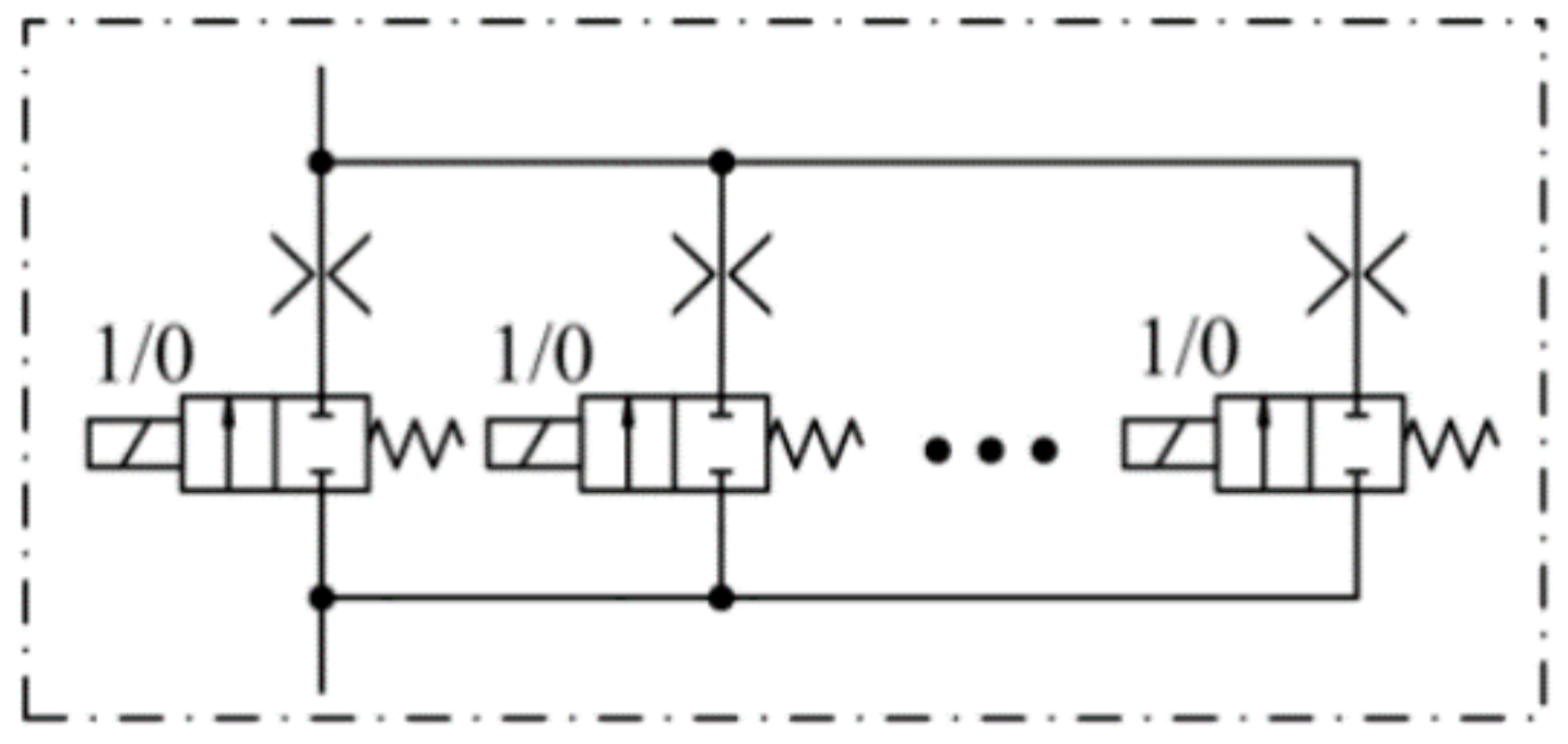
2.2.1. Parallel Digital Hydraulic Technology

The parallel digital hydraulic technology requires all the components to be connected in parallel, and the composite states of all the components are controlled by modulated discrete digital signals. Different composite states give different discrete fluid flows which can be used to realize intelligent control of system output. The parallel digital hydraulic system has a fixed number of discrete outputs which depend on the composite state of components, and it does not need frequent on/off switching of components.

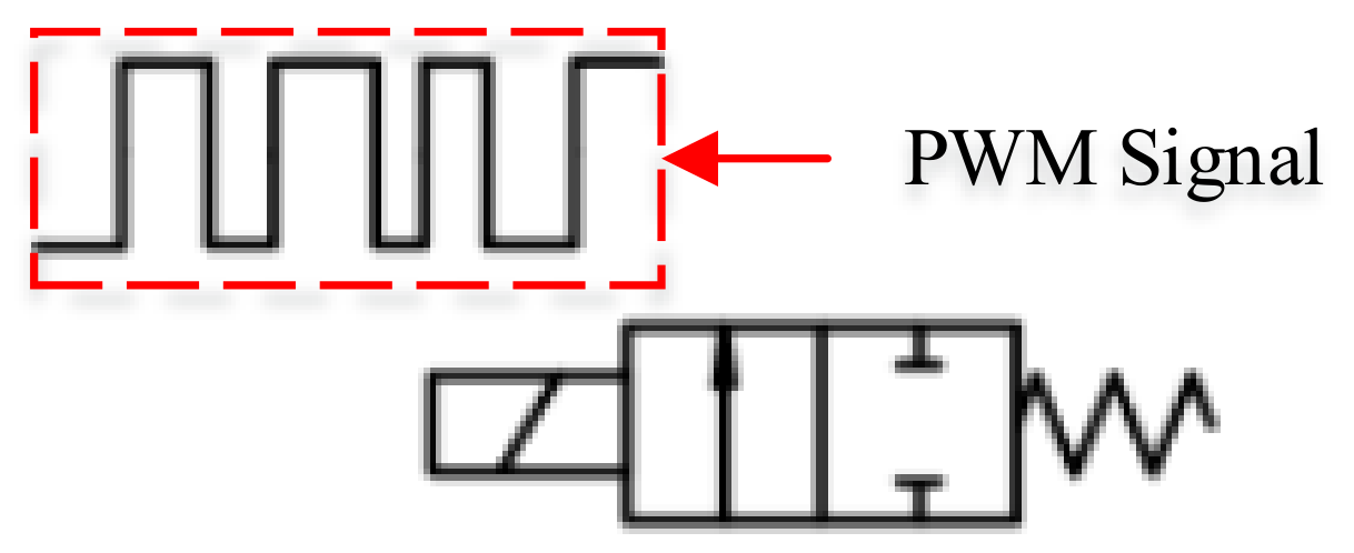
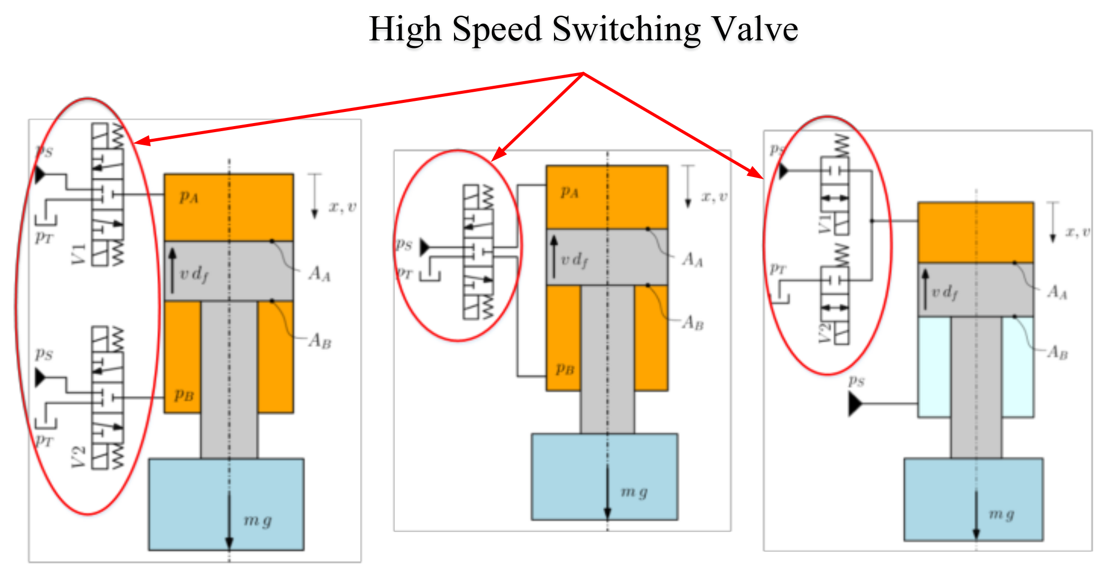
2.2.2. High-Speed Switching Digital Hydraulic Technology

In order to realize intelligent control of system output, high-speed switching digital hydraulic technology put forward high requirements for high-speed switching components which can switch quickly and continuously to output fluid flow with different discrete values. Theoretically, the output of high-speed switching digital hydraulic system can be any value within a certain range, but it is still a discrete quantity due to the switching frequency of components. However, if the switching frequency is very high or the switching quantity is fine enough, the pulsation caused by the discrete quantity to the system can be acceptable in the control system. And if the pulse width modulation (PWM) signal is used to control the high-speed switching components, the output is proportional to the width of pulse.

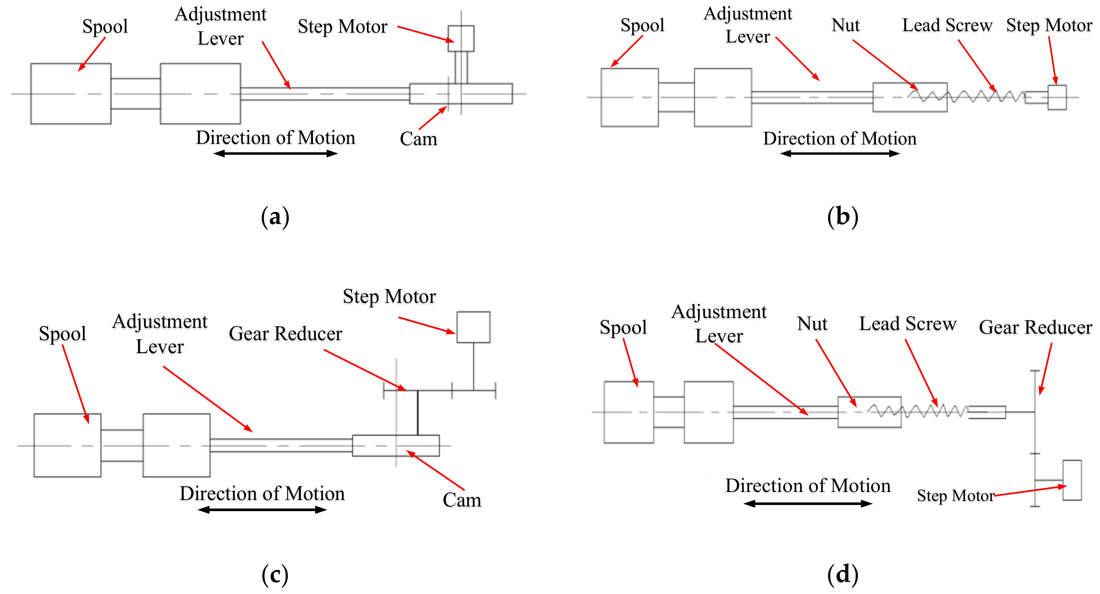
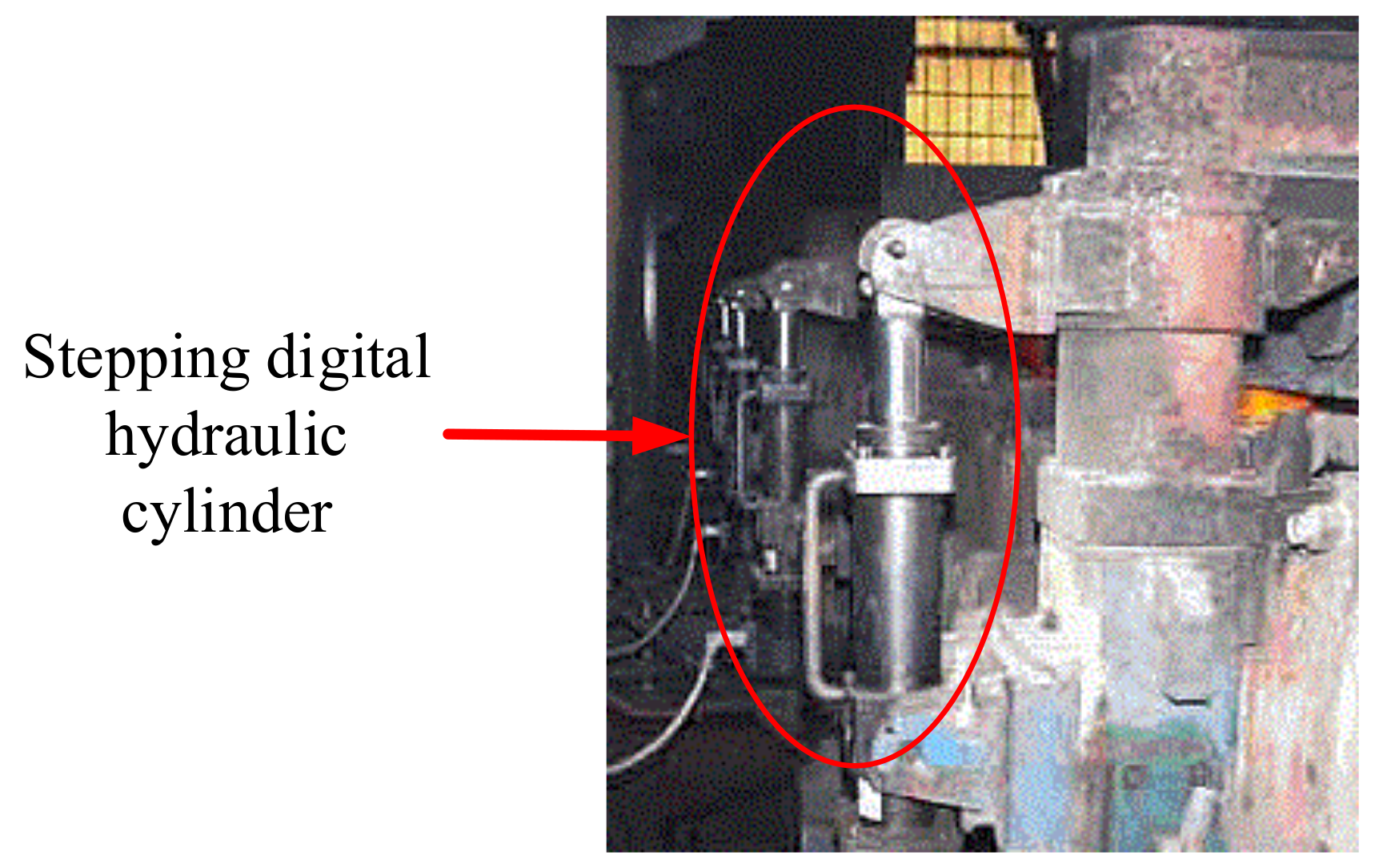
2.2.3. Stepping Digital Hydraulic Technology

The stepping digital hydraulic technology relies on precise stepping motor which controlled by modulated discrete digital signals. The rotation of stepping motor can be used to control the movement of the spool though a mechanical structure. So, the discrete fluid flow can be obtained to realize intelligent control of the system output.
The key of stepping digital hydraulic technology is the accurate conversion between the rotation of stepping motor and the movement of the spool.

3. Digital Hydraulic Components

As with the traditional hydraulic components, digital ones also contain three main categories: digital control components (digital hydraulic valve), digital power components (digital hydraulic pump, transformer and power control system) and digital actuators (digital hydraulic cylinder and motor). And all kinds of components with different classifications of digital hydraulic technology also have different products.

3.1. Digital Hydraulic Valve

According to different working principles, digital hydraulic valve can be divided into three different types.

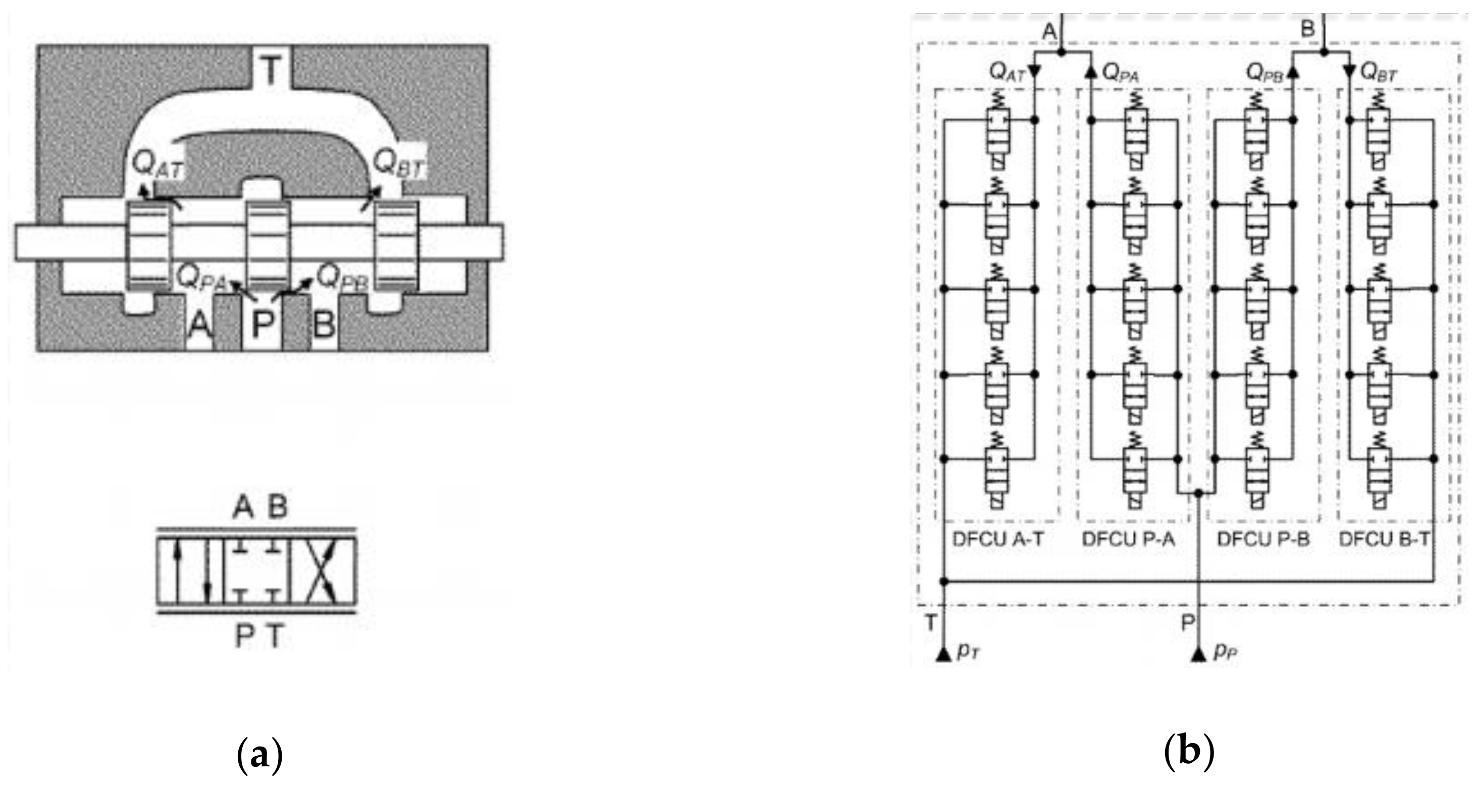
3.1.1. Parallel Digital Hydraulic Valves

The parallel digital hydraulic valve also can be called a digital flow control unit (DFCU). It can realize the accurate flow control through encoding control of multiple switching valves connected in parallel. Figure 1 shows the working principle of a typical parallel digital two-way valve.
The flow rate of a DFCU is the sum of all the switching valves’ flow which are set to the “on” state. DFCU’s steady-state characteristics are affected by two factors: the number of switching valves (N) and the encoding mode of switching valves’ control signal. The commonly used encoding methods are binary encoding, Fibonacci encoding and PNM (pulse number modulation) encoding. There are 2N combinations of switching valves, which can be named the states of DFCU. So, there are 2N kinds of flow output under different states of DFCU. The essential difference between DFCU and a high-speed switching digital hydraulic valve is that the former does not require the frequent switching of one single valve between on and off to obtain continuous system output. And the state switching of a valve is only used to adjust the state of DFCU [8].
Similarly, if DFCU is used for independent metering control, the function of three-position four-way valve (which is shown in Figure 2a) can also be realized. The working principle is shown in Figure 2b. And each metering of this valve is independently and precisely controlled by DFCU, which is composed of five switching valves [9].

3.1.2. High-Speed Switching Digital Hydraulic Valve

The high-speed switching digital hydraulic valve is also called pulse modulation switching digital hydraulic valve. Figure 3 shows the working principle of a typical high-speed switching two-way valve. The on/off switching of a valve is controlled by the pulse signal with high/low electrical level. And the average flow of a valve is controlled by the digital signal of high frequency modulation [10]. Among the signal modulation modes, pulse width modulation (PWM) is one of the most commonly used. Theoretically, the controllable flow rate of the valve can be set to any value, but the ratio of the maximum to minimum flow rate can only change in a limited range due to the dynamic characteristics of the valve itself. The control performance of a high-speed switching valve is directly related to the switching frequency. Low frequency control performance is better but will cause obvious pressure pulsation and noise.
If a high-speed switching valve is used for independent metering control, the function of four-way valve, as shown in Figure 2a, can be achieved, and its working principle is shown in Figure 4.

3.1.3. Stepping Digital Hydraulic Valve

A stepping digital hydraulic valve controls the duty cycle of input pulse signal (which can be represented by the rotation angle and rotation speed of stepping motor) through PWM encoding, so as to realize the active intelligent position control of the spool. Because the stepping motor has no accumulated error and almost no hysteresis, the stepping digital hydraulic valve has a higher positional accuracy of the spool. Four typical forms of stepping digital hydraulic valves are shown in Figure 5 [11].
However, the stepping motor outputs rotational motion, which needs to be transformed into linear motion to drive the spool. So, the conversion mechanisms, such as cam and ball screws, are indispensable. But all of the conversion mechanisms have great friction and inertia, which affects the frequency response characteristics of a stepping digital hydraulic valve. In addition, the stepping motor is prone to being out-of-step at high frequency. These problems limit the application of stepping digital hydraulic valves.

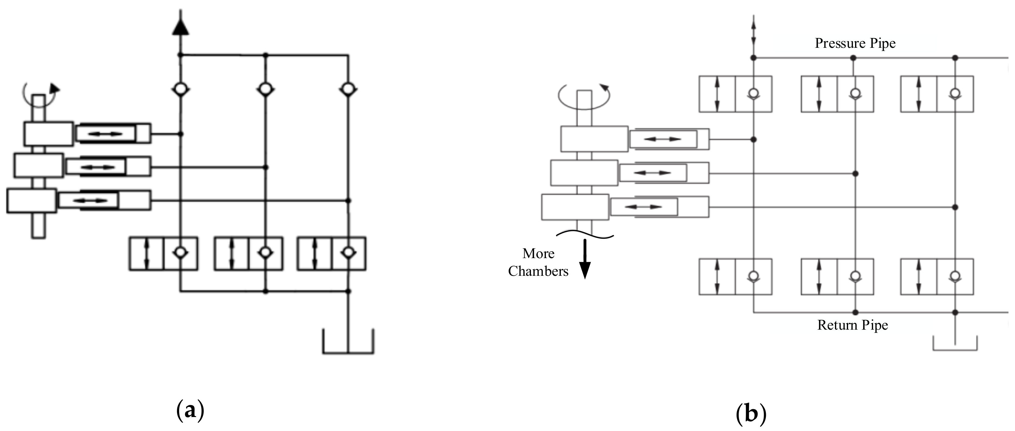
3.2. Digital Hydraulic Pump

The function of the digital hydraulic pump can be realized through the digital control of its output variation. The research on it mainly includes the variable output control of the quantitative pump and the variable mode control of the variable pump.

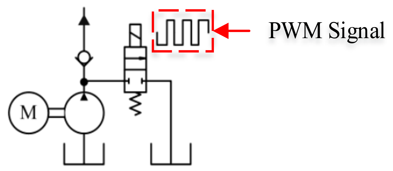
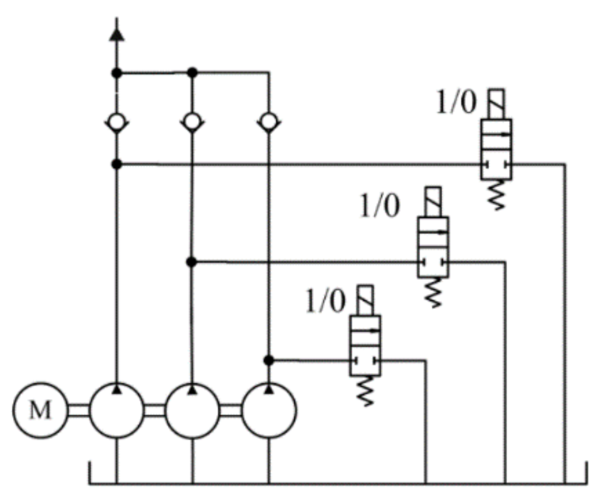
3.2.1. Variable Output Control of Quantitative Pump

Figure 6 shows the principle of high-speed switching digital hydraulic pump, which is composed of the quantitative hydraulic pump and high-speed switching valve.
High-speed switching digital hydraulic pump regulates the inlet-flow of the system through the high-speed switching valve at the outlet of the quantitative pump. And its control performance is directly related to the switching frequency of the valve.
The parallel digital hydraulic pump consists of several coaxial quantitative pumps in parallel; its working principle is shown in Figure 7.
Each quantitative pump in a parallel digital hydraulic pump system is independently controlled by switching valve at outlet of each quantitative pump. The maximum displacement is the sum of the displacements of all quantitative pumps in parallel; the minimum displacement is the displacement of minimum quantitative pump; the displacement between maximum and minimum displacement depends on the encoding mode of the switching valves. So, a parallel digital hydraulic pump has 2N kinds of displacement (N is the number of quantitative pumps in parallel). The essential difference between parallel digital hydraulic pump and high-speed switching digital hydraulic pump is that the former does not need to control the output of the system through one single switching valve’s frequently state change between on and off. The state changing of switching valves is only used to adjust the combined form of parallel pumps.
The piston chamber independent control digital hydraulic pump can realize the active and intelligent control of displacement commendably. The working principle of such a pump is shown in Figure 8a. And it can be seen that each piston chamber of the digital hydraulic pump can be switched between working state and no-load state independently under the control of switching valves. The average displacement of the pump depends on the ratio of working piston chamber number and the no-load piston chamber number. In addition, with switching valves applied to pumps or hydraulic motors, it is possible to use a part of the stroke of each cylinder as well, in order to obtain more flexible system output.
Figure 8b shows the piston chamber independent control digital hydraulic pump-motor. The working principle is the same as that of the piston chamber independent control digital hydraulic pump, but it can be switched to be a motor. When it turns to be a digital motor, its rotation speed can be controlled by turning the switching valve on and off at high frequencies [12].

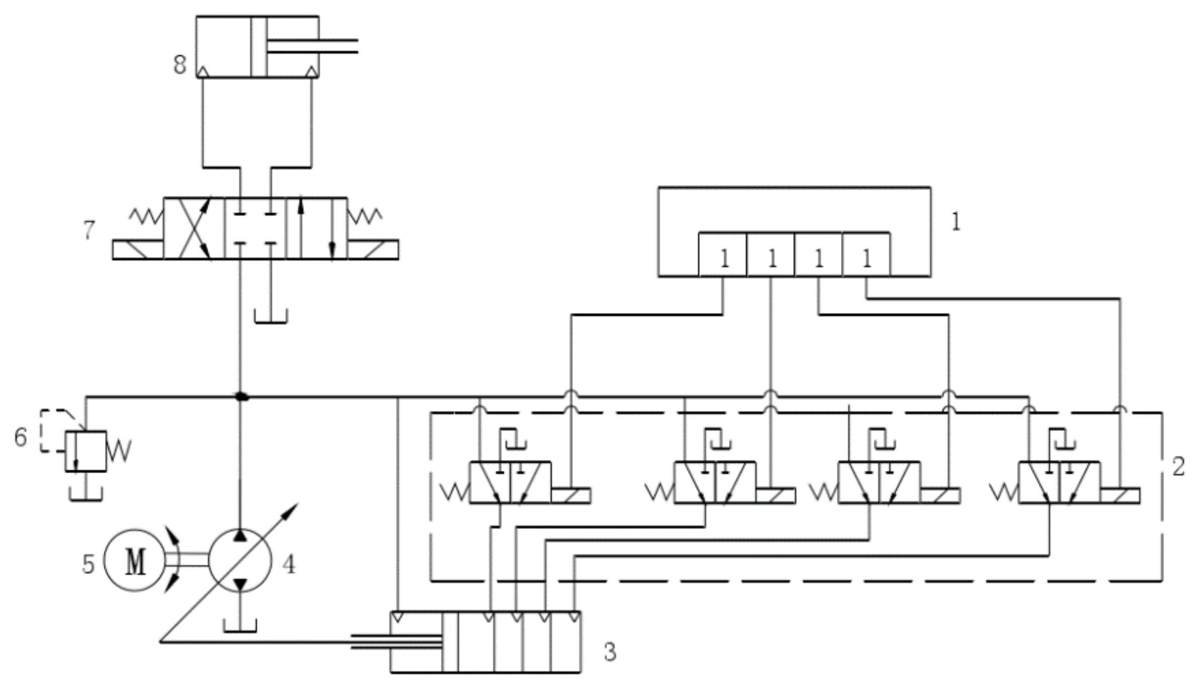
3.2.2. Digital Control of a Variable Pump

The working principle of combination cylinder control digital hydraulic pump is shown in Figure 9. When the controller outputs different code under the control of digital input signal, the number of opened switching valves varies, as does the input flow of the combined cylinder, which makes the extension length of piston rod vary. And the piston rod can control the inclination of the swash plate to realize the intelligent control of pump displacement. This kind of digital hydraulic pump can obtain different pressures and flow rates according to different encoding combinations. When the combination cylinder has N level combinations, there are 2N kinds of pump displacement [13]. But this is just a theoretical possibility, because the forces on the swash plate are very much variable actually, and a force control on the swash plate is not enough to obtain a displacement control.
Stepping motor control digital hydraulic pump takes the stepping motor as the driver of variable mechanism to realize the intelligent displacement control. As shown in Figure 10, the stepping motor receives the input digital signal, and converts its rotary motion to the linear motion of the spool through the conversion mechanism (such as cam and ball screw). Finally, the spool drives the variable piston rod to change the inclination of the swash plate to realize the hydraulic pump displacement control [14].
The high-speed switching valve control digital hydraulic pump adjusts the extension length of piston rod by switching the state of the high-speed switching valve between on and off at high frequency. And the extension length of piston rod can be used to control the inclination of the swash plate to realize the intelligent control of pump displacement. The working principle of such a pump is shown in Figure 11 [15].

3.3. Digital Hydraulic Transformer

The hydraulic transformer is a new type of hydraulic component based on the constant pressure network secondary regulation system. It can adjust the system pressure to any value within the pressure variation range without throttling loss, and such a process is reversible, which means that the system can output energy to the load or recover energy from the load to the accumulator. However, the low-speed operation stability, the robustness and vibration noise of hydraulic transformer limit its application [16]. Digital hydraulic technology provides two possible solutions. The one is high-speed switching digital hydraulic transformer, which is composed of high-speed switching valves with appropriate hydraulic impedance (Figure 12a); the other is parallel linear digital hydraulic transformer, which is composed of hydraulic cylinders with multi-piston chambers (Figure 12b) [8].

3.4. Digital Hydraulic Power Control System

The digital hydraulic power control system (DHPMS) is an integrated volumetric component which can provide multiple independent outputs [8]. Its working pressure can be adjusted actively and adaptively according to working conditions. Figure 13a,b shows two forms of the DHPMS.
The piston type DHPMS (Figure 13a) is derived from the digital pump-motor shown in Figure 8b. The switching valves allow any piston chamber to be switched between working state and no-load state. The quantitative pump-motor type DHPMS is composed of two coaxial pump-motors, as shown as Figure 13b, and its input/output is controlled by the switching valves. A certain DHPMS with a different structure has the common, interesting feature of every independent outlet behaving like a digital pump-motor. That means the hydraulic power from the load lowering can be recovered to the accumulator, even if accumulator pressure is higher than load pressure. Thus, the whole energy storing capacity of the accumulator can be utilized [8].

3.5. Digital Hydraulic Actuator

3.5.1. Digital Hydraulic Cylinder

According to the different control methods, there are three kinds of digital hydraulic cylinder: the stepping digital hydraulic cylinder, the high-speed switching valve control digital hydraulic cylinder and the parallel digital hydraulic cylinder.
The stepping digital hydraulic cylinder (which is shown as Figure 14) controls the rotation angle and rotation speed of the stepping motor by PWM encoding of digital signal. The stepping motor’s rotation can be converted into the position change of the spool. So, the flow rate of oil coming in or out of the hydraulic cylinder can be controlled intelligently and digitally and the position control of piston can be realized.
The working principle of the high-speed switching valve control digital hydraulic cylinder is similar to that of the high-speed switching valve control hydraulic motor, which is shown in Figure 15a. The flow rate coming in or out of the cylinder (the displacement of the piston rod) can be adjusted through the duty cycle of PWM signal, which is used to control the high-speed switching valve. However, because the flow rate of the current high-speed switching valve is generally small, this kind of hydraulic cylinder is difficult to adapt to the conditions with high pressure and large flow.
Parallel digital hydraulic cylinder can be realized in a variety of ways, the simplest of which is to connect multiple hydraulic cylinders in parallel. The working principle is shown in Figure 15a; it controls the flow rate come in or out of the cylinder (the displacement of the piston rod) through the switching valves. However, the integration of such a system is poor. So, it needs a large installation space [8].
To avoid the deficiency of multiple cylinders in parallel connection, researchers designed some parallel digital hydraulic cylinders with integrated multiple piston cavities, whose principles are shown in Figure 15b,c. At present, this kind of parallel digital hydraulic cylinder can be integrated with up to four piston cavities, and it can provide 16 kinds of discrete output forces under different combinations of the switching valves. And this kind of cylinder can also obtain more kinds of output force by increasing the number of discrete pressure sources. When N is the number of discrete pressure sources and M is the number of piston cavities, NM kinds of force can be output. Similar to other parallel digital hydraulic components, the parallel digital hydraulic cylinder has different dynamic/static characteristics with different encoding modes of the switch valves. The weak point is that continuous switching between control modes is required in order to obtain quasi-steady velocity. The situation is not so demanding as in the switching systems because there are much more force values available [8].

3.5.2. Digital Hydraulic Motor

There are two main kinds of digital hydraulic motors: high-speed switching valve control hydraulic motors and parallel digital hydraulic motors.
A high-speed switching valve control hydraulic motor can be realized in two ways, the principles of which are shown in Figure 16a,b respectively. The high-speed switching digital hydraulic motor shown in Figure 16a controls the duty cycle of PWM signal to adjust the flow rate or pressure of the hydraulic motor. So, the rotation speed or torque of the motor can be controlled digitally [8]. Figure 16b shows the digital flow distribution hydraulic motor with low speed and high torque; it uses five sets of high-speed switching valves (two valves for each set) to control the flow distribution of the five piston chambers [17]. So, the output torque of the motor can be controlled digitally and intelligently.
The principle of the parallel digital hydraulic motor is shown in Figure 17; it is composed of multiple coaxial hydraulic motors in parallel, in which each motor is independently controlled by the switching valve [8]. The maximum torque is the sum torque of all the motors in parallel; the minimum torque is the torque of the minimum motor. And the torque between the maximum torque and minimum torque depends on the different encoding mode of the switch valves.

4. Features and Advantages of Digital Hydraulic Technology

In 2013, the concept of “Industry 4.0” was officially launched at Hanover Industrial Expo, aiming to improve the intelligent level of the manufacturing industry. Industry believes that the concept of “Industry 4.0” is the fourth industrial revolution or revolutionary production method led by intelligent manufacturing. “Industry 4.0” mainly includes three aspects; namely, intelligent factories, intelligent production and intelligent logistics. As one of the important transmission technologies in industrial systems, the hydraulic system is required to be more energy efficient, more accurate and more reliable. However, as mentioned before, the low energy efficiency and high cost of conventional hydraulic technology are against such requirements. As the inheritor and innovator of traditional hydraulic technology, digital hydraulic technology is in line with “Industry 4.0.” Its unique technical features and advantages will provide technical support for the development of manufacturing industry in the developmental trend of “Industry 4.0.”

4.1. Features of Digital Hydraulic Technology

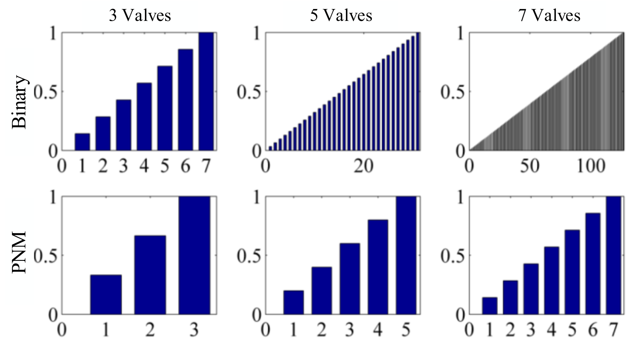
4.1.1. Discrete Output

Discrete output is the most basic feature of a parallel digital hydraulic system. When the number of components in parallel is N, the system has 2N kinds of combinations of components (this is also called the state of the system). In theory, each system state generates a discrete output, but in practice, the actual number of output values depends on the coding method and the relative size of components in parallel. This section will introduce two extreme cases of output values. The minimum number of output values is achieved by using components with the same size. And the control signal is coded by pulse number modulation (PNM), which means the control signal is a certain number of pulses with the same width and amplitude. Because the components in parallel are the same size, it would not make sense for a single component in the system to receive a pulse signal, and what makes sense is the number of components receiving the pulse signal. That means the number of output values is same as the number of components receiving the pulse signal, and under such a condition the number of outputs values is N+1 (one is the condition that no component receives the pulse signal). The maximum number of output values is achieved by using components with entirely different sizes and the encoding of components adopting binary code. In this case, the system discrete output number is 2N. And the outputs of a DFCU system with such two extreme cases are shown in Figure 18.
It can be seen that binary encoding can achieve a more linear output when the number of valves in parallel is the same.

4.1.2. Fast Response Time Independent of Amplitude

Since each component of the parallel digital hydraulic system works independently, DFCU can realize a direct flow rate mutation from 0% to 100% by opening all the components in parallel at the same time. That means the DFCU has a 2 ms full amplitude response time, which is the same as the switching valve. Conversely, the full amplitude response time of 3 ms is only a dream for traditional pump technology. Such a feature is especially important in the energy efficient cylinder control, because it can improve the production efficiency, which is one of the key features of smart factory in “Industry 4.0.”

4.2. Advantages of Digital Hydraulic Technology

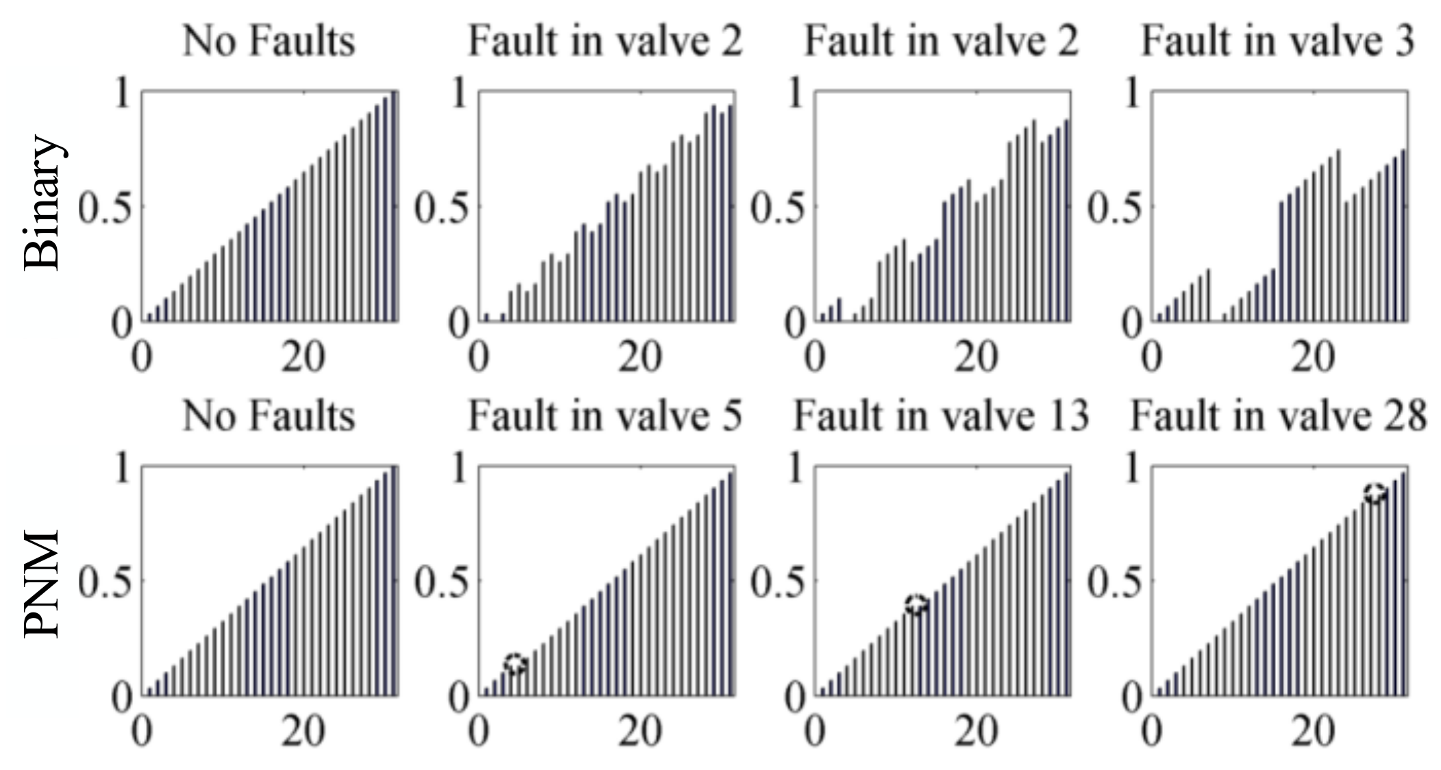
4.2.1. Fault-Tolerance Performance

The intelligent factory in “Industry 4.0” puts forward higher requirements for the fault-tolerant performance of hydraulic system, because it is an important factor to ensure production efficiency, and it is also one of the shortcomings of conventional hydraulic technology. But for the parallel digital hydraulic systems, fault-tolerance is an inherent feature. The components in parallel are independent of each other, and the system can maintain the original performance to a large extent when individual components fail. It should be noted that the fault-tolerance performance of parallel digital hydraulic system is closely related to the encoding mode of components in parallel. The fault-tolerance performance is best when the PNM code used to control the state of the system, and it is the opposite when using the binary code. Figure 19 shows fault-tolerance performance of the system when 5-bit binary code and 31-bit PNM code are adopted in case of “valve fails to turn on” [8]. But it has to be said that the “valve does not close” is a more difficult situation. And this problem also plagues researchers very much, and a large proportion of current research on control algorithms is about it.

4.2.2. Precise Lossless Control

Intelligent logistics is one of the three themes of “Industry 4.0,” and it put forward higher requirements for the mobile outdoor robotic applications, wherein high power density, ruggedness and reliability are key features. So, the low efficiency of conventional proportional control can be a limitation. However, because the high-speed switching valves can turn on/off at high frequencies, the system does not cause excessive oil supply, so the accurate control with high energy efficiency has become the most prominent feature of high-speed switching digital hydraulic system. Take the hydraulic buck converter (HBC) as an example. It is controlled by the switching valve, and its schematic and prototype are shown in Figure 20 [18].
Figure 21 shows the graphs of the measured pressures and efficiencies and the efficiency improvement to a proportional drive that provides same pressure and flow rate and works with the same supply pressure pS. It shows that the measured efficiency of the high-speed switching system reaches 70–85%. At the same time, the HBC has quite a constant efficiency profile in a large operating range, and the improvements over resistance control are higher for low operating pressures when resistance control has high pressure losses [18]. In addition, we can see from Figure 22 that the HBC has the same control accuracy as the hydraulic proportional control system (pLHPD).

4.2.3. High Accuracy Sensorless Control

Precise position control is an important actuation function in intelligent manufacturing. The conventional approach uses a cylinder with a precise position sensor and a closed loop control via a proportional or servo valve. Although its control accuracy is very high, the costs and low reliability caused by sensor, cabling, connectors and controller input modules are the main factors limiting the conventional proportional or servo valve system’s application. So, the avoidance of such sensors is an effective measure to improve system reliability and make it survive and develop in “Industry 4.0.” And digital hydraulic technology is providing possible approaches of high accuracy sensorless control.
A hydraulic stepping actuator is presented by Andreas Plöckinger, and its schematic is shown in Figure 23.
The basic idea is to use a digital stepping unit to control the load force instead of pressure sensor. So, the load force is automatically fed back via the valve. Thus, the system would be a real “sensorless” hydraulic stepping actuator [19]. The mechanical design of the test rig is shown in Figure 24a.
And we can see from Figure 24c that the position error is with ±0.8 µm and the relative error is less than 0.17%. For that the error after 50, 100, 200, 300, 400, 600 steps and at different forces from 10 kN to 90 kN were measured and calculated. The maximum absolute error is less than 16 µm and the relative error less than 0.55%.

4.3. Advantages and Challenges of Digital Hydraulic Technology

By integrating the technical features of parallel digital hydraulic system and high-speed switching digital hydraulic system, it can be seen that digital hydraulic technology has unique advantages over traditional hydraulic technology.
  • Digital hydraulic technology directly adopts the digital signal to control without D/A conversion, which simplifies the control mode; makes the signal data storage, processing and transmission more convenient; and has stronger disturbance rejection ability, which is helpful for improving the robustness of the system.
  • The digital hydraulic system has a better integration and programmability which can improve the application and maintenance performance of the system. It also facilitates networking of the system.
  • The performance of the system depends on the control of the combination state of components rather than the performance of individual components. Therefore, simple and reliable components can be widely used to improve the robustness and fault-tolerance performance of the system.
  • The digital hydraulic system avoids the use of proportional and servo components, and it improves the anti-pollution performance.
  • It is easier to realize independent metering control. And because of the switching control mode, the system can reduce the throttle loss and improve efficiency.
  • Digital hydraulic technology has obvious advantages, but there are also challenges to limit its application.
  • The high frequency switching of the components can cause noise and pressure impact.
  • The durability of high-speed switching hydraulic technology severely limits its application at present.
  • The parallel digital hydraulic technology needs to use a large number of components, and such a situation would cause a dramatic increase in size and cost.
  • A complex, unconventional control strategy would also bring difficulties to the application of digital hydraulic technology.

5. Developments and the Current Situation of Digital Hydraulic Technology

5.1. Parallel Digital Hydraulic Technology

The idea of using multiple hydraulic valves in parallel has existed since the birth of the hydraulic valves. In the document that can be found at present, as early as 1930, Rickenberg applied a patent regarding using three electromagnetic valves with different flow rates in parallel [20]. Murphy [21] also applied for a patent of a four-way valve for which the load-side is independently controlled by using DFCU. Virvalo [22] achieved the application of DFCU in the velocity control of hydraulic cylinder in 1978. However, due to the basic computer technology at that time, the parallel technology was difficult to be applied in practice. With the development of the computer technology, research and applications of the parallel technology are gradually becoming abundant.

5.1.1. Parallel Digital Hydraulic Components

At present, parallel digital hydraulic valve technology is one of the most significant research directions among the parallel digital hydraulic technology. Represented by Tampere University of Technology, the University of Aalborg and the Federal University of the State of Santa Catarina have conducted in-depth research on the parallel digital hydraulic valve technology. Among them, Linjama of Tampere University of Technology and his team put forward the basic definition of DFCU based on ordinary commercial valve earlier, and they tested the dynamic and static characteristics of DFCU [23,24,25].
After that, the team carried out a series aimed at the control strategy [26,27], pressure peak [28], fault detection [29] and energy saving [30,31] of DFCU. And they successfully applied the DFCU to a paper cutting machine; it is superior to the traditional hydraulic system in terms of cost, control performance and energy saving [32,33]. Now, a new generation DFCU that can integrate more switching valves is being developed [34]. Some researchers have carried out research on improving DFCU energy efficiency and fault-tolerant performance, and they also achieved some results [9,35].
The use of the parallel digital hydraulic pump (which is shown in Figure 7) can be dated back to the London water supply system in 1883 [36], and it was applied in many industries due to its excellent control and energy saving performance. However, research about the parallel digital hydraulic pump is hardly seen; only in the 1980s were there some studies on its control and energy saving [37,38]. There are more studies aimed at the digital hydraulic pump-motor (which is shown in Figure 9b); Artemis started research on the piston hydraulic pump-motor in the 1980s, but the results were not published until the 1990s [39,40,41]. At present, the six-piston digital pump-motor developed by Artemis can realize the independent control of each piston chamber. At the same time, Tampere University and Purdue University also carried out some research on piston-type digital hydraulic pump-motor [42,43,44].
The research of the parallel digital hydraulic actuator mainly centers on the hydraulic cylinder. Tampere university has studied the impedance control of a three-piston parallel digital hydraulic cylinder, and the experimental results show that the energy loss of the parallel digital hydraulic cylinder in the system with constant input pressure is reduced by 30%–60% compared with the traditional hydraulic cylinder [45]. At the same time, Linjama also found that when adopting the secondary regulation hydraulic source without throttling, the parallel digital hydraulic cylinder can achieve better energy saving effect, and this conclusion was verified by the experiment of a four-piston parallel digital hydraulic cylinder [46]. Furthermore, De Gier carried out abundant research on application of the parallel digital hydraulic cylinders with multiple pistons in high-speed and high-pressure stamping machines. He increased the movement speed of the piston rod by reducing the piston area, and he increased the output force of the hydraulic cylinder by increasing the piston area [47].

5.1.2. Application of the Parallel Digital Hydraulic Technology

The parallel digital hydraulic technology is mainly used in two aspects: direct parallel control of components and applications of parallel digital valve.
Direct parallel control of components is realized by multiple components with the same/different specifications connected in parallel, and the number of components in the accessed system (which can be considered as the output/input of the system) is intelligently controlled by combination of switching valves. Direct parallel control of components mainly contains the parallel digital hydraulic pump shown in Figure 7 and the parallel digital hydraulic motor shown in Figure 17.
The application of the parallel digital valve is the main research direction of parallel digital hydraulic technology. Bishop E. has developed a parallel linear hydraulic transformer with unique advantages over traditional hydraulic transformers in terms of pressure ratio, response time and transfer efficiency [48]. The team of Tampere University of Technology creatively has put forward the definition of digital hydraulic momentum control system (DHPMS), and published its simulation analysis results for the first time in 2009 [49,50], and their experimental analysis results were published in the following year. The results show that DHPMS has obvious advantages in terms of control performance and energy efficiency [51]. At present, the research and development of the second generation DHPMS (which is shown in Figure 25) have also made breakthroughs [52].
Johan Ersfolk optimized the parallel digital valve control of hydraulic cylinders by using a modern embedded graphics processing unit (GPU), and the results showed that the large-scale parallel characteristics brought by the GPU enabled the controller to obtain better control performance than conventional controllers [53].

5.2. High-Speed Switching Digital Hydraulic Technology

The automobile industry has greatly promoted the development of high-speed switching digital hydraulic technology. The high-speed switching valves which can turn on and off more than 1000 times per second are the first and the most widely applied in the ABS braking system [54,55].
The high-pressure fuel injection technology which emerged around the year of 2000 put forward a series of technical requirements for high-speed switching valve. Since the working pressure is 200 Mpa, it requires that the valve can realize five times on/off switching for each combustion. And the valve failures are not allowed during vehicle service. Although the high-speed switching solenoid valve in the automobile industry generally has a small flow rate and is not suitable for hydraulic system, its successful promotion and application have proved that the high-speed switching technology is feasible and reliable. And that is the reason why some valves in the automobile industry are mentioned below when the high-speed switching digital hydraulic valve is introduced.

5.2.1. High-Speed Switching Digital Hydraulic Valve

The research of high-speed switching hydraulic technology focuses on the R&D of high-speed switching valves, which has two aspects. The one is the research and development of new high-speed switching valves, and the other is the control method of high-speed switching valves.
The development of the high-speed switching valve can be traced back to the end of the 1970s. The company Lucas in Britain developed the high-speed solenoid switching valve using two special shape electromagnets: spiral tube type and taper type, which were called the “Helenoid valve” and “Colenoid valve.” They overcame the problem that the acceleration of armature is inversely proportional to electromagnetic force.
But due to their complicated structures and difficulty in processing and manufacturing, they are not widely used [56,57]. Since then, many companies and research institutions launched various types of high-speed switching valves. BKM company launched a three-way spherical, cartridge type, high-speed electromagnetic switching valve with a response time of 2–3 ms, and its working pressure is 10 MPa [58]. But this valve can only be used for direct digital control of electronic unit injectors because of its small flow rate. Yukio Tanaka developed a two-way high-speed switching valve and a three-way high-speed switching valve in the 1980s; their response times are all around 3 ms [59].
In the late 1980s, Masahiko Miyamoto developed an ultra-high-pressure high-speed switching valve with working pressure of 120 MPa and response time of 0.4 ms [60,61,62]. However, because these valves do not overcome the small flow rate, their applications are limited to the field of fuel injection. Bosch company also successfully developed a high-speed electromagnetic switching valve suitable for an ultra-high-pressure environment, and its response time is between 0.3 and 0.65 ms [63]. Linz center developed a high frequency switching ball valve which is shown in Figure 26a, and the spool is controlled by current feedback. The spool position of this valve is only 5 mm, and its frequency response is up to 1 kHz; its flow rate can reach 14 L/min [64]. But for now, the exemplary application for such a valve could be the actuation of automotive wet clutches; in particular, those of dual clutch systems. Tampere optimized the surface material and the heat-treatment process of the cone valve, and they obtained a high-speed switching water hydraulic valve with high reliability and long service life (which is shown in Figure 26b) [65]. Minnesota university developed a rotary high-speed switching valve with a special structure pilot spool which is shown in Figure 26c; this valve’s maximum flow rate is 40 L/min, and its frequency response is 100 Hz [66]. Zhejiang University designed a PZT piezoceramic high-speed switching valve with temperature compensation, which is shown in Figure 26d. This valve’s working pressure can reach 20 MPa, and its frequency response and flow rate are, respectively, 200Hz and 10 L/min [67]. Guizhou Honglin machinery factory cooperated with BKM company developed a thread cartridge HSV high-speed electromagnetic switching valve, whose opening time is 3 ms, and closing time is 2 ms. This valve ‘s highest working pressure is 20 MPa, and its flow rate can reach 2–9 L/min [68].
Zhejiang University of Technology developed a high-speed switching valve with a high frequency and large flow rate. This valve’s working pressure is 21 Mpa, and its flow rate is 450 L/min. The spool position of the valve reaches 6 mm, but the response time is only about 8 ms [69].
The control of high-speed switching valve has a crucial effect on its performance, but few commercial controllers can be used for high-speed switching valve at present [70,71]. To solve such a problem, Linjama developed a set of controllers with response time of 8–12 ms that can directly control the cartridge valve [59]. Zhejiang University put forward an intelligent voltage control method based on current feedback. The self-adaptability of coil resistance makes the excitation time of each voltage segment vary adaptively with the change of coil resistance. And such a control method keeps the dynamic characteristics of the valve at a high level during its working procedure [72]. Wuhan University proposed a zero-flow switching control method, which enables the spool of high-speed switching valve to always switch at the zero-flow point; it avoids the pressure impact and energy loss caused by high-frequency switching [73].

5.2.2. Applications of High-Speed Switching Hydraulic Technology

Because the current high-speed switching valves generally have a small flow rate, they are mostly used as the pilot control parts of other hydraulic components to achieve hydraulic components’ intelligent digital. Among them, the pilot control of a proportional valve emerged in the 1990s as a successful example [74,75,76].
With the continuous development of high-speed switch technology, its application is gradually widespread. Minnesota University used high-speed switching valves to control the input/output of each piston chamber of a low-speed radial hydraulic motor with large torque (which is shown in Figure 27a). And so far, such a digital motor is used as part of a 7 MW wind turbine drive train (which is shown in Figure 27b). The application of high-speed switching valves improves the energy efficiency of the hydraulic motor [77]. Tyler Helmus also adopted a similar method to control the hydraulic pump-motor, and he also achieved excellent control effect of the pump-motor [78].
Yang huayong proposed a variable axial piston pump control method (which is shown in Figure 28) using high-speed switching valve for pilot control, and the experimental results proved that this method also has excellent control effect [79].
Rainer Haas used different high-speed switching valve layouts to carry out position control of the hydraulic cylinder (which is shown in Figure 29). And he analyzed the position and speed response of the hydraulic cylinder with different control strategies [80].
Scheidl and his research team carried out a series of studies on the control method and energy-saving of high-speed switching hydraulic torque converters. Among them, one small torque converter obtains an average efficiency of 80% when the maximum output power is 1 kW [18,81,82]. Marcos Paulo Nostrani used the high-speed switching technology to control the hydraulic transformer, and they reduced its energy consumption effectively [83]. Shi Guanglin realized precise control of the pneumatic robot by using high-speed switching valves [84].

5.3. Stepping Digital Hydraulic Technology

The development of the stepping digital hydraulic technology is thanks to the mature stepping motor technology. Especially after the 1980s, the stepping motor control method was more flexible and diverse because the cheap microcomputer with multiple functions had appeared in industry. Therefore, the stepping motor gradually met the functional requirements of controlling hydraulic components [85]. But there are still some problems, such as the lower rotation speed, the small torque, falling out-of-step under high frequency, etc. So, the development and popularization of stepping digital hydraulic technology are still limited. What is more, with the development and perfection of parallel digital hydraulic technology and high-speed switching hydraulic technology, the research on the stepping digital hydraulic technology are gradually reduced.

5.3.1. Stepping Digital Hydraulic Components

The R&D of the stepping digital hydraulic valve is more advanced in Japan, and relevant studies and applications have also been carried out in France, Britain, Canada and other countries [86,87,88]. Among them, the stepping-type digital flow valve and pressure valve of Tokyo Keiki formed a complete product line. The pressure of the valves can reach 210 Mpa, and the flow rate is 1–500 L/min. And the repeatability accuracy and hysteresis accuracy are less than 0.1% [89]. In addition, the companies Yuken, Toyooki, Uchida, Sperry, Vickers, Danfos, Beijing Aemetec Digital Hydraulic Ltd., etc. produced stepping digital hydraulic valve products.
Among them, a 2D digital hydraulic valve developed by Zhejiang University of Technology is the most distinctive. The spool of this valve has dual degrees of freedom; one is the rotation around the axis, and the other is the linear motion along the axis. Stepping motor drives the spool to rotate in a certain angle range through the transmission mechanism to realize the function of the pilot valve. And there is a spiral groove on the inner surface of the valve sleeve, the linear motion of the spool is driven by the area difference between the low-pressure hole, the high-pressure hole and the spiral groove to realize the function of the main valve. Its working principle is shown in Figure 30 [90]. At present, 2D digital hydraulic valve has formed a relatively complete product series, and they have already been put into service in the aviation industry.
Research on stepping digital hydraulic cylinder began in the 1960s and 1970s; the world’s first digital hydraulic cylinder was exhibited in Olympia Hall by Germany. Since then, the company of Rexroth, Tokyo Keiki, Beijing Aemetec Digital Hydraulic Ltd., etc. have developed a variety of stepping digital hydraulic cylinders with various structures [91].

5.3.2. Applications of Stepping Digital Hydraulic Technology

The most important applications of stepping digital hydraulic technology are the use of customized digital hydraulic cylinders/valves to achieve accurate position/speed control in extreme environments. At the same time, accurate synchronization control of multiple hydraulic cylinders has also been widely applicated. Among them, the most representative digital cylinder/valve products come from Beijing Aemetec Digital Hydraulic Ltd. (Beijing, China); their products have been successfully applied in a number of military engineering, large water conservancy engineering and metallurgical engineering applications [92,93,94]. For example, a stepping digital hydraulic cylinder is used for the crystallizer liquid level automatic control system (which is shown in Figure 31).

6. Developing Trend of the Digital Hydraulic Technology

After decades of research, digital hydraulic components have formed a series of products with complete functions and various categories. Some products have been used in aerospace, construction machinery, shipbuilding industry and other industries; its technology has become increasingly mature. However, under the development trend of high speed, high pressure and high power to weight ratio of hydraulic system, the problems such as lower flow rate, lower allowable pressure and serious dispersion of system have also become more prominent. To solve such problems, researchers have also invested a lot of energy into optimizing the existing digital hydraulic products. Some of the research results have not only been applied in engineering, but also evolved into some developmental direction of digital hydraulic technology.

6.1. Development of a New Valve Prototype

High-speed switching digital hydraulic technology puts forward the technical index of switching frequency 500 Hz (that means the opening time is 2 ms) for high-speed switching valve. However, the flow rate of the current valve which can reach such a technical index is generally small. So, the valves cannot satisfy the need of continuous switching control under large flow. Therefore, many research institutions and universities have invested a lot of resources in the R&D of new valves, and they had put forward different valve prototypes, but few valve products can be put into industrial applications. It can be concluded that the R&D of new high-speed switching valves with high working pressure and large flow rate will become an inevitable trend of digital hydraulic technology.

6.2. Integration of Digital Hydraulic Technology

Parallel digital hydraulic technology and high-speed switching digital hydraulic technology, are two main branches of current digital hydraulic technology; they have their own unique technological advantages and face different challenges. Therefore, it is also a research direction of digital hydraulic technology to combine the two main branches of current digital hydraulic technology and take their respective advantages. For example, Huova replaced the smallest switching valve unit in DFCU with high-speed switching valve, which successfully reduced the pressure impact of single high-speed switching control. At the same time, they also obtain accurate speed control of hydraulic cylinders [95].

6.3. Improvement of Energy Efficiency

One of the important characteristics of digital hydraulic technology which is different from traditional hydraulic technology, is that it can realize intelligent hydraulic energy supply based on the system requirements. So, digital hydraulic components, such as the digital hydraulic pump-motor, digital hydraulic transformer, DHPMS etc., all have high energy efficiency in theory, but that still needs a lot of experimental verification and optimization. Therefore, improving energy efficiency is also an important development trend of digital hydraulic technology.

7. Conclusions

This paper explains the mainstream definition of digital hydraulics, and it gives a more accurate definition of digital hydraulic technology. Meanwhile, this paper presents a review of developmental works on digital hydraulic components and digital hydraulic technology. The main outcomes of this review work are as follows:
  • With the continuous promotion of “Industry 4.0” in the world, traditional hydraulic technology has been marginalized because of its low energy efficiency and lack of intelligence. The digital hydraulic technology will be able to make up for the defects of the traditional hydraulic technology, and play a greater role in intelligent factories and intelligent manufacturing.
  • With the advantages of great fault-tolerance and fast response performance, parallel digital hydraulic technology has become one of the mainstream research directions in digital hydraulic technology. But it still needs to solve the problems of high cost and large volume after a large number of switching components are connected in parallel. At the same time, the lack of accurate and suitable control algorithms of parallel systems has also become an important factor hindering the development of parallel digital hydraulic technology.
  • High-speed switching digital hydraulic technology is also one of the main research directions in digital hydraulic technology. It can achieve precise lossless control performance, and its response time can also reach considerable millisecond level. However, the development and application of high-speed switching digital hydraulic technology are restricted by the vibration, noise, pulsation and other problems caused by the frequent opening and closing of high-speed switching valve, and the lives of high-speed switch components themselves. At the same time, the problem of high-speed switching valves’ insufficient service lives also needs to be solved.
  • The development of stepping digital hydraulic technology started earlier. And it is famous for its high accuracy, sensorless control performance which can greatly simplify a system and improve the system’s usability and maintainability. However, the application and development of digital hydraulic technology are limited because the stepping motor is prone to being out-of-step at high frequency. In recent years, with the continuous development and improvement of parallel technology and high-speed switching technology, the stepping digital hydraulic technology has faded out of the mainstream research direction of digital hydraulic technology.
  • The “Workshop on Digital Fluid Power” held by Tampere university is the most famous academic conference on digital hydraulic technology in the world. Looking at the papers published in the conference in recent years, it can be seen that the main research directions of researchers on digital hydraulic technology are focused on control algorithms, new valve prototypes, digital pump motors, etc. The purpose of researchers is to further improve the energy efficiency, reliability and practicability of digital hydraulic technology, and lay a foundation for promoting the practical application of digital hydraulic technology.
The definition of Industry 4.0 promotes the progress of the whole society and industrial system. Only the technology that meets the needs of society can survive and develop. And digital hydraulic technology provides a feasible way for the traditional hydraulic industry to develop in the direction of intelligence and greenness. At the same time, as the innovation of and successor to traditional hydraulic technology, digital hydraulic technology will certainly make fluid power technology developing in line with “Industry 4.0.”
With continuous in-depth research, digital hydraulic technology will continue to innovate. More mature digital hydraulic components will also have more extensive engineering application prospects.

Author Contributions

Q.Z. is responsible for article writing and research on digital hydraulic technology. X.K. is responsible for the general idea of this article, and he gives the defination of digital hydraulic technology. B.Y. investigates the digital hydraulic components. K.B. investigates the features and advantages of digital hydraulic technology. Z.J. investigates the developments and the current situation of digital hydraulic technology. Y.K. investigates the developing trend of digital hydraulic technology. All authors have read and agreed to the published version of the manuscript.

Funding

This research was funded by NATIONAL KEY RESEARCH AND DEVELOPMENT PROGRAM, grant number 2018YFB2000701, and the NATIONAL NATUAL SCIENCE FOUNDATION OF CHINA, grant number 51975506.

Conflicts of Interest

The authors declare no conflict of interest.

References

  1. Lu, Y. History progress and prospects of fluid power transmission and control. Chin. J. Mech. Eng. 2010, 46, 1–9. [Google Scholar]
  2. Ba, K.; Yu, B.; Zhu, Q.; Gao, Z.; Kong, X. The position-based impedance control combined with compliance-eliminated and feedforward compensation for HDU of legged robot. J. Frankl. Inst. 2019, 356, 9232–9253. [Google Scholar] [CrossRef]
  3. Ba, K.; Yu, B.; Gao, Z.; Ma, G.; Kong, X. An improved force-based impedance control method for the legged robot HDU. Isa Trans. 2019, 84, 187–205. [Google Scholar] [CrossRef] [PubMed]
  4. Achten, P. Convicted to innovation in fluid power. Proc. Inst. Mech. Eng. Part I 2010, 224, 619–621. [Google Scholar] [CrossRef] [Green Version]
  5. Kagoshima, M.; Komiyama, M.; Nanjo, T.; Tsutsui, A. Development of new kind of hybrid excavator. Res. Dev. Kobe Steel Eng. Rep. 2007, 57, 66–69. [Google Scholar]
  6. Scheidl, R. Discussion: Is the future of fluid power digital? Proc. Inst. Mech. Eng. Part I 2012, 226, 724–727. [Google Scholar]
  7. Yang, H. Progress and Trend of Construction Machinery Intelligence; Construction Machinery Technology and Management: Beijing, China, 2017; pp. 19–21. [Google Scholar]
  8. Linjama, M. Digital Fluid Power—State of the Art. In Proceedings of the Twelfth Scandinavian International Conference on Fluid Power, Tampere, Finland, 18–20 May 2011. [Google Scholar]
  9. Linjama, M. On The Numerical Solution of Steady-State Equations of Digital Hydraulic Valve Actuator System. In Proceedings of the Eighth Workshop on Digital Fluid Power, Tampere, Finland, 24–25 May 2016. [Google Scholar]
  10. Zhao, X. Research on the Theory and Application of HGDV pulse Modulation Switching Digital Hydraulic Valve. Master’s Thesis, Lanzhou University of Technology, Lanzhou, China, 2005. [Google Scholar]
  11. Yang, H. Development direction of digital hydraulic valve technology. In Proceedings of the Shanghai: 9th FPTC-2016, Shanghai, China, 21–24 November 2016. [Google Scholar]
  12. Breidi, F.; Helmus, T.; Lumkes, J. The Impact of Peak-and-Hold and Reverse Current Solenoid Driving Strategies on the Dynamic Performance of Commercial Cartridge Valves in a Digital Pump/Motor. Int. J. Fluid Power 2015, 17, 37–47. [Google Scholar] [CrossRef]
  13. Ding, X. Research on Digital Hydraulic Valve Controlling Axial Piston Pump. Master’s Thesis, Taiyuan University of Science and Technology, Taiyuan, China, 2015. [Google Scholar]
  14. Wang, Q. Study of the Digital Control Variable Axial Piston Pump and its SCM Control. Master’s Thesis, Shenyang University of Technology, Shenyang, China, 2015. [Google Scholar]
  15. Liu, Z. Research on Electro-Hydraulic Digital Control of Constant Pressure Variable Pump System. Mach. Tool Hydraul. 2001, 2, 29–31. [Google Scholar]
  16. Yang, H.; Ouyang, X.; Xu, B. Development status of hydraulic transformer. J. Mech. Eng. 2003, 39, 1–5. [Google Scholar] [CrossRef]
  17. Shi, G.; Yu, L.; Qi, L. Simulation of Radial Piston Constant Flow Pump with Digital Distribution under Random Low Speed Driving. In Proceedings of the Eighth Workshop on Digital Fluid Power, Tampere, Finland, 24–25 May 2016. [Google Scholar]
  18. Kogler, H.; Scheidl, R.; Ehrentraut, M.; Guglielmino, E.; Semini, C.; Caldwell, D.G. A Compact Hydraulic Switching Converter for Robotic Applications. In Proceedings of the Fluid Power and Motion Control (FPMC2010), Bath, UK, 15–17 September 2010; Johnston, D.N., Plummer, A., Eds.; Hadleys Ltd.: Theale, UK, 2010; pp. 55–68. [Google Scholar]
  19. Plöckinger, A.; Grad, C.; Scheid, R. High Accuracy Sensorless Hydraulic Stepping Actuator. In Proceedings of the Eighth Workshop on Digital Fluid Power, Tampere, Finland, 24–25 May 2016. [Google Scholar]
  20. Rickenberg, F. Valve. U.S. Patent No. 1757059, 30 April 1930. [Google Scholar]
  21. Murphy, R.; Weil, J. Hydraulic Control System. U.S. Patent No. 3038449, 20 June 1962. [Google Scholar]
  22. Virvalo, T. Cylinder Speed Synchronization. Hydraul. Pneum. 1978, 31, 55–57. [Google Scholar]
  23. Linjama, M.; Koskinen, K.T.; Vilenius, M. Pseudo-Proportional Position Control of Water Hydraulic Cylinder Using On/Off Valves. In Proceedings of the Fifth JFPS International Symposium on Fluid Power, Nara, Japan, 12–15 November 2002; pp. 155–160. [Google Scholar]
  24. Laamanen, A.; Linjama, M.; Tammisto, J.; Koskinen, K.T.; Vilenius, M. Velocity Control of Water Hydraulic Motor. In Proceedings of the Fifth JFPS International Symposium on Fluid Power, Nara, Japan, 12–15 November 2002; pp. 167–172. [Google Scholar]
  25. Laamanen, A.; Linjama, M.; Vilenius, M. Characteristics of a Digital Flow Control Unit with PCM Control. In Proceedings of the Seventh Triennial International Symposium on Fluid Control, Measurement and Visualization, Sorrento, Italy, 25–28 August 2003. ISBN 0-9533991-4-1. [Google Scholar]
  26. Linjama, M.; Koskinen, K.T.; Vilenius, M. Accurate Trajectory Tracking Control of Water Hydraulic Cylinder with Non-Ideal on/Off Valves. Int. J. Fluid Power 2002, 4, 7–16. [Google Scholar] [CrossRef]
  27. Linjama, M.; Vilenius, M. Improved Digital Hydraulic Tracking Control of Water Hydraulic Cylinder Drive. Int. J. Fluid Power 2005, 6, 29–39. [Google Scholar] [CrossRef]
  28. Siivonen, L.; Linjama, M.; Huova, M.; Vilenius, M. Pressure based fault detection and diagnosis of a digital valve system. In Proceedings of the Power Transmission and Motion Control (PTMC 2007), Bath, UK, 12–14 September 2007; Johnston, D.N., Plummer, A., Eds.; Hadleys Ltd.: Theale, UK, 2007; pp. 67–79. [Google Scholar]
  29. Siivonen, L.; Linjama, M.; Huova, M.; Vilenius, M. Jammed On/Off Valve Fault Compensation with Distributed Digital Valve System. Int. J. Fluid Power 2009, 10, 73–82. [Google Scholar] [CrossRef]
  30. Linjama, M.; Huova, M.; Vilenius, M. Online Minimization of Power Losses in Distributed Digital Hydraulic Valve System. In Proceedings of the 6th International Fluid Power Conference Dresden, Dresden, Germany, 1–2 April 2008; Volume 1, pp. 157–171. [Google Scholar]
  31. Huova, M.; Karvonen, M.; Ahola, V.; Linjama, M.; Vilenius, M. Energy Efficient Control of Multiactuator Digital Hydraulic Mobile Machine. In Proceedings of the 7th International Fluid Power Conference, Aachen, Germany, 22–24 March 2010; Volume 1, pp. 25–36. [Google Scholar]
  32. Linjama, M.; Hopponen, V.; Ikonen, A.; Rintamäki, P.; Vilenius, M.; Pietola, M. Design and Implementation of Digital Hydraulic Synchronization and Force Control System. In Proceedings of the 11th Scandinavian International Conference on Fluid Power SICFP’09, Linköping, Sweden, 2–4 June 2009. 13p. [Google Scholar]
  33. Hopponen, V.; Linjama, M.; Ikonen, A.; Rintamäki, P.; Pietola, M.; Vilenius, M. Energy Efficient Digital Hydraulic Force Control. In Proceedings of the 11th Scandinavian International Conference on Fluid Power SICFP’09, Linköping, Sweden, 2–4 June 2009. 11p. [Google Scholar]
  34. Linjama, M.; Karvonen, M. Digital Microhydraulics. In Proceedings of the First Workshop on Digital Fluid Power, Tampere, Finland, 3 October 2008; Linjama, M., Laamanen, A., Eds.; pp. 141–152. [Google Scholar]
  35. Linjama, M.; Huova, M.; Karhu, O.; Huhtala, K. Energy Efficient Tracking Control of a Mobile Machine Boom Mockup. In Proceedings of the Eighth Workshop on Digital Fluid Power, Tampere, Finland, 24–25 May 2016. [Google Scholar]
  36. Pugh, B. The Hydraulic Age—Public Power Supplies before Electricity; Mechanical Engineering Publications Ltd.: London, UK, 1980; 176p. [Google Scholar]
  37. Lambeck, R.P. Hydraulic Pumps and Motors: Selection and Application for Hydraulic Power Control Systems; Dekker: New York, NY, USA, 1983; 154p. [Google Scholar]
  38. Moorhead, J.R. Saving Energy with “Digital” Pump Systems. Mach. Des. 1984, 56, 40–44. [Google Scholar]
  39. Rampen, W.H.S.; Salter, S.H. The Digital Displacement Hydraulic Piston Pump. In Proceedings of the 9th International Symposium on Fluid Power, Cambridge, UK, 25–27 April 1990; BHR Group: Cambridge, UK, 1990; pp. 33–46. [Google Scholar]
  40. Ehsan, M.; Rampen, W.H.S.; Salter, S.H. Modeling of Digital-Displacement Pump-Motors and Their Application as Hydraulic Drives for Nonuniform Loads. Asme J. Dyn. Syst. Meas. Control 2000, 122, 210–215. [Google Scholar] [CrossRef]
  41. Payne, G.S.; Kiprakis, A.E.; Ehsan, M.; Rampen, W.H.S.; Chick, J.P.; Wallace, A.R. Efficiency and Dynamic Performance of Digital DisplacementTM Hydraulic Transmission in Tidal Current Energy Converters. Proc. Inst. Mech. Eng. Part A 2007, 221, 207–218. [Google Scholar] [CrossRef]
  42. Tammisto, J.; Huova, M.; Heikkilä, M.; Linjama, M.; Huhtala, K. Measured Characteristics of an In-Line Pump with Independently Controlled Pistons. In Proceedings of the 7th International Fluid Power Conference, Aachen, Germany, 22–24 March 2010; Volume 1, pp. 361–372. [Google Scholar]
  43. Lumkes, J.; Batdorff, M.; Mahrenholz, J. Characterization of Losses in Virtually Variable Displacement Pumps. Int. J. Fluid Power 2009, 10, 17–27. [Google Scholar] [CrossRef]
  44. Merril, K.J.; Lumkes, J.H., Jr. Operating Strategies and Valve Requirements for Digital Pump/Motors. In Proceedings of the 6th FPNI—PhD Symposium, West Lafayette, IN, USA, 15–19 June 2010; pp. 249–258. [Google Scholar]
  45. Huova, M.; Laamanen, A. Control of Three-Chamber Cylinder with Digital Valve System. In Proceedings of the Second Workshop on Digital Fluid Power, Linz, Austria, 12–13 November 2009; Scheidl, R., Winkler, B., Eds.; pp. 94–105. [Google Scholar]
  46. Linjama, M.; Vihtanen, H.-P.; Sipola, A.; Vilenius, M. Secondary Controlled Multi-Chamber Hydraulic Cylinder. In Proceedings of the 11th Scandinavian International Conference on Fluid Power SICFP’09, Linköping, Sweden, 2–4 June 2009. 15p. [Google Scholar]
  47. De Gier, G. Hydraulic Cylinder for Use in a Hydraulic Tool. Patent EP1580437, 15 September 2004. [Google Scholar]
  48. Bishop, E.D. Digital Hydraulic Transformer—Approaching Theoretical Perfection in Hydraulic Drive Efficiency. In Proceedings of the Ninth Scandinavian International Conference on Fluid Power, Linköping, Sweden, 2–4 June 2009. 19p. [Google Scholar]
  49. Linjama, M.; Huhtala, K. Digital pump-motor with independent outlets. In Proceedings of the 11th Scandinavian International Conference on Fluid Power SICFP’09, Linköping, Sweden, 2–4 June 2009. 16p. [Google Scholar]
  50. Linjama, M.; Tammisto, J. New Alternative for Digital Pump-Motor Transformer. In Proceedings of the Second Workshop on Digital Fluid Power, Linz, Austria, 12–13 November 2009; Scheidl, R., Winkler, B., Eds.; pp. 49–61. [Google Scholar]
  51. Heikkilä, M.; Tammisto, J.; Huova, M.; Huhtala, K.; Linjama, M. Experimental Evaluation of a Piston-Type Digital Pump-Motor-Transformer with Two Independent Outlets. In Proceedings of the Fluid Power and Motion Control (FPMC 2010), Bath, UK, 15–17 September 2010; Johnston, D.N., Plummer, A., Eds.; pp. 83–97. [Google Scholar]
  52. Heikkilä, M.; Tammisto, J.; Linjama, M.; Huhtala, K. Digital Hydraulic Power Management System—Measured Characteristics of a Second Prototype. In Proceedings of the Eighth Workshop on Digital Fluid Power, Tampere, Finland, 24–25 May 2016. [Google Scholar]
  53. Ersfolk, J.; Boström, P.; Timonen1, V.; Westerholm1, J.; Wiik, J.; Karhu, O.; Linjama, M.; Waldén, M. Optimal Digital Valve Control Using Embedded, GPU. In Proceedings of the Eighth Workshop on Digital Fluid Power, Tampere, Finland, 24–25 May 2016. [Google Scholar]
  54. Ballard, R.L. System for Minimizing Skidding. U.S. Patent No 3528708, 18 February 1968. [Google Scholar]
  55. Wennmacher, G. Untersuchung und Anwendung Schnellschaltender Elektrohydraulischer Ventile für den Einsatz in Kraftfahrzeugen. Ph.D. Thesis, RWTH Aachen University, Aachen, Germany, 1995. [Google Scholar]
  56. Seilly, A.H. Helenoid Actuators—A New Definition in Extremely Fast Acting Solenoids. SAE Paper, 790119; SAE International: Warrendale, PA, USA, 1979. [Google Scholar]
  57. Seilly, A.H. Colenoid Actuators-Further Developments in Extremely Fast Acting Solenoids. SAE Paper, 810462; SAE International: Warrendale, PA, USA, 1979. [Google Scholar]
  58. Beck, N.J.; Barkhimer, R.L.; Calkins, M.A.; Johnson, W.P.; Weseloh, W.E. Direct Digital Control of Electronic Unit Injectors, SAE 840273; SAE International: Warrendale, PA, USA, 1979; pp. 21332–21340. [Google Scholar]
  59. Tanaka, H. Digital Control and Application of Hydraulic and Pneumatic; Chongqing University Press: Chongqing, China, 1992. [Google Scholar]
  60. Tanaka, H. Research on high speed electromagnetic on-off valve. Transaclions Jsme 1984, 50, 1594–1601. [Google Scholar] [CrossRef]
  61. Tanaka, H. Digital control and its application. Oil Air Compression Design. 1984, 22, 16–23. [Google Scholar]
  62. Tanaka, H.; Tanaka, H.; Araki, K. Digital control of three-way high-speed solenoid valve. Trans. Jsme (B) 1984, 50, 2663–2666. [Google Scholar] [CrossRef]
  63. Zou, Z. Research on 2D Digital Valve and Electromechanical Converter. Master’s Thesis, Zhejaing University of Technology, Hangzhou, China, 2010. [Google Scholar]
  64. Florian, M.; Rudolf, S. Development and Experimental Results of a Small Fast Switching Valve Derived from Fuel Injection Technology. In Proceedings of the Eighth Workshop on Digital Fluid Power, Tampere, Finland, 24–25 May 2016. [Google Scholar]
  65. Paloniitty, M.; Matti, L.; Huhtala, K. Durability Study on High Speed Water Hydraulic Miniature On/Off-Valve. In Proceedings of the Eighth Workshop on Digital Fluid Power, Tampere, Finland, 24–25 May 2016. [Google Scholar]
  66. Rannow, M.B.; Li, P.Y.; Chase, T.R. Discrete Piston Pump/Motor Using a Mechanical Rotary Valve Control Mechanism. In Proceedings of the Eighth Workshop on Digital Fluid Power, Tampere, Finland, 24–25 May 2016. [Google Scholar]
  67. Ouyang, X.; Yang, H.Y.; Jiang, H.; Xu, B. Simulation of the Piezoelectric High-speed on/off Valve. Chin. Sci. Bull. 2008, 53, 2706–2711. [Google Scholar] [CrossRef]
  68. Liu, P.; Fan, L.; Hayat, Q.; Xu, D.; Ma, X.; Song, E. Research on Key Factors and Their Interaction Effects of Electromagnetic Force of High-Speed Solenoid Valve. Sci. World J. 2014, 2014, 567242. [Google Scholar] [CrossRef] [PubMed]
  69. Zhang, B.; Ruan, J.; Nie, W. Dynamic response analysis of high-speed locking valve. J. Mech. Electr. Eng. 2008, 25, 69–72. [Google Scholar] [CrossRef]
  70. Plöckinger, A.; Scheidl, R.; Winkler, B. Performance, Durability and Applications of a Fast Switching Valve. In Proceedings of the Second Workshop on Digital Fluid Power, Linz, Austria, 12–13 November 2009; Scheidl, R., Winkler, B., Eds.; pp. 129–143. [Google Scholar]
  71. Zöppig, V.; Neumann, K. Switching Magnetic Valve Electronics. In Proceedings of the 7th International Fluid Power Conference (7th IFK), Aachen, Germany, 22–24 March 2010; Volume 2, pp. 407–418. [Google Scholar]
  72. Zhong, Q.; Zhang, B.; Yang, H.; Ma, J.; Fung, R. Performance analysis of a high-speed on/off valve based on an intelligent pulse-width modulation control. Adv. Mech. Eng. 2017, 9. [Google Scholar] [CrossRef]
  73. Peng, S. The Definition of a Zero-Flowrate-Switching Controller. In Proceedings of the Eighth Workshop on Digital Fluid Power, Tampere, Finland, 24–25 May 2016. [Google Scholar]
  74. Sauer-Danfoss. PVE Series 4 for PVG 32, PVG 100 and PVG 120, Technical Information. In Sauer-Danfoss Brochure No 520L0553 Rev EA; Sauer-Danfoss: Ames, IA, USA, 2010; 32p. [Google Scholar]
  75. Becker, U. The Behavior of a Position Controlled Actuator with Switching Valves. In Proceedings of the Fourth Scandinavian International Conference on Fluid Power, Tampere, Finland, 26–29 September 1995; pp. 160–167. [Google Scholar]
  76. Muto, T.; Yamada, H.; Tsuchiya, S. A Precision Driving System Composed of a Hydraulic Cylinder and High-Speed ON/OFF Valves. In Proceedings of the 49th National Conference on Fluid Power, Las Vegas, NV, USA, 19–21 March 2002; pp. 627–638. [Google Scholar]
  77. Roemer, D.B.; Norgaard, C.; Bech, M.M.; Johansen, P. Valve and Manifold Considerations for Efficient Digital Hydraulic Machines. In Proceedings of the Eighth Workshop on Digital Fluid Power, Tampere, Finland, 24–25 May 2016. [Google Scholar]
  78. Helmus, T.; Breidi, F.J., Jr. Simulation of a Variable Displacement Mechanically Actuated Digital Pump Unit. In Proceedings of the Eighth Workshop on Digital Fluid Power, Tampere, Finland, 24–25 May 2016. [Google Scholar]
  79. Zhang, B.; Hong, H.; Zhong, Q.; Guan, R.; Yang, H. A Pilot Control Method for a Variable Displacement Axial Piston Pump Using Switching Technology. In Proceedings of the Eighth Workshop on Digital Fluid Power, Tampere, Finland, 24–25 May 2016. [Google Scholar]
  80. Haas, R.; Hinterbichler, C.; Lukachev, E.; Schoberl, M. Optimal Digital Hydraulic Feed-forward Control Applied to Simple Cylinder Drives. In Proceedings of the Eighth Workshop on Digital Fluid Power, Tampere, Finland, 24–25 May 2016. [Google Scholar]
  81. Scheidl, R.; Riha, G. Energy Efficient Switching Control by a Hydraulic Resonance-Converter. In Proceedings of the Workshop on Power Transmission and Motion Control (PTMC 1999), Bath, UK, 8–11 September 1999; Burrows, C.R., Edge, K.A., Eds.; pp. 267–273. [Google Scholar]
  82. Scheidl, R.; Mikota, G. The Role of Resonance in Elementary Hydraulic Switching Control. Proc. Inst. Mech. Eng. Part I 2003, 217, 469–480. [Google Scholar] [CrossRef]
  83. Nostrani, M.P.; Galloni, A.; Raduenz, H.; De Negri, V.J. Theoretical and Experimental Analysis of a Hydraulic Step-Down Switching Converterfor Position and Speed Control. In Proceedings of the Eighth Workshop on Digital Fluid Power, Tampere, Finland, 24–25 May 2016. [Google Scholar]
  84. Shi, G.; Lee, B.; Yang, L. On the Control Strategy for Pneumatic Robot Driven by High Speed Solenoid On/OFF Valves above Rough Ground. In Proceedings of the Eighth Workshop on Digital Fluid Power, Tampere, Finland, 24–25 May 2016. [Google Scholar]
  85. Liu, B. The Study of Exactly Congtrol Stepping Motor. Master’s Thesis, Shandong University, Jinan, China, 2010. [Google Scholar]
  86. Trostmann, E. Water Hydraulics Control Technology; Danfoss: Nordborg, Denmark, 1996. [Google Scholar]
  87. Koskinen, K.T.; Vilenius, M.J.; Virvalo, T. Water as a pressure medium in position servo systems. In Proceedings of the Forth Scandinavian International Conference on Fluid Power, Tampere, Finland, 26–29 September 1995. [Google Scholar]
  88. Urata, E.; Miyakawa, S.; Yamashina, C.; Nakao, Y.; Usami, Y.; Shinoda, M. Development of a water hydraulic servovalve. Jsme Int. J. Ser. B 1998, 41, 286–294. [Google Scholar] [CrossRef] [Green Version]
  89. Zhang, Q. Research on the Static and Dynamic Characteristics of the 2D Digital Valve and Compensation of the Dead Zone Nonlinear. Master’s Thesis, Zhejiang University of Technology, Hangzhou, China, 2011. [Google Scholar]
  90. Li, S.; Ruan, J.; Meng, B. Dither Compensation Technology for Hysteresis of 2D Digital Valve. Trans. Chin. Soc. Agric. Mach. 2012, 42, 208–218. [Google Scholar]
  91. Katakura, H.; Yamane, R.; Takenka, T. Fundamental research on digital positioning by several hydraulic cylinder and a microcomputer. J. Jpn. Hydraul. Pneum. Soc. 1991, 22, 63–70. [Google Scholar]
  92. Yang, S. Unusual Hydraulic Synchronization and By-talking Experience on Innovation. Hydraul. Pneum. Seals 2015. [Google Scholar] [CrossRef]
  93. Yang, T. Talking about the Digital Hydraulic by YIMEIBO. Hydraul. Pneum. Seals 2017, 37, 16–19. [Google Scholar]
  94. Aemetec Co. Ltd. [EB/OL]. Available online: http://www.china-hydraulic.com/ (accessed on 17 October 2019).
  95. Huova, M.; Plöckinger, A. Improving Resolution of Digital Hydraulic Valve System by Utilizing Fast Switching Valves. In Proceedings of the Third Workshop on Digital Fluid Power, Tampere, Finland, 13–14 October 2010; Laamanen, A., Linjama, M., Eds.; pp. 79–92. [Google Scholar]
Figure 1. Parallel digital two-way valve.
Applsci 10 00579 g001
Figure 2. Two kinds of four-way valve: (a) traditional three-position four-way valve; (b) digital flow control unit (DFCU) four-way valve.
Applsci 10 00579 g002
Figure 3. High-speed switching two-way valve controlled by pulse width modulation (PWM).
Applsci 10 00579 g003
Figure 4. High-speed switching four-way valve.
Applsci 10 00579 g004
Figure 5. Four typical forms of stepping digital hydraulic valves: (a) cam type; (b) screw nut type; (c) gear reducer-cam type; (d) gear reducer-screw nut type.
Applsci 10 00579 g005
Figure 6. High-speed switching digital hydraulic pump.
Applsci 10 00579 g006
Figure 7. Parallel digital hydraulic pump.
Applsci 10 00579 g007
Figure 8. The piston chamber’s independent control digital hydraulic components: (a) the digital hydraulic pump; (b) the digital hydraulic pump-motor.
Applsci 10 00579 g008
Figure 9. The digital hydraulic pump controlled by the combination cylinder.
Applsci 10 00579 g009
Figure 10. Digital hydraulic pump controlled by the stepping motor.
Applsci 10 00579 g010
Figure 11. Digital hydraulic pump controlled by high-speed switching valve.
Applsci 10 00579 g011
Figure 12. Digital hydraulic transformers: (a) high-speed switching digital hydraulic transformer; (b) parallel linear digital hydraulic transformer.
Applsci 10 00579 g012
Figure 13. Digital hydraulic power control system: (a) piston type digital hydraulic power control system (DHPMS); (b) quantitative pump-motor type DHPMS.
Applsci 10 00579 g013
Figure 14. Stepping digital hydraulic cylinder.
Applsci 10 00579 g014
Figure 15. Parallel digital hydraulic cylinders: (a) multiple cylinder parallel connection mode; (b) parallel digital hydraulic cylinder with multiple piston cavities (1); (c) parallel digital hydraulic cylinder with multiple piston cavities (2).
Applsci 10 00579 g015aApplsci 10 00579 g015b
Figure 16. Hydraulic motors each controlled by a high-speed switching valve: (a) high-speed switching digital hydraulic motor; (b) flow distribution digital hydraulic motor with low speed and high torque.
Applsci 10 00579 g016
Figure 17. Parallel digital hydraulic motor.
Applsci 10 00579 g017
Figure 18. The output of the system with different encoding modes.
Applsci 10 00579 g018
Figure 19. Fault freedom of DFCUs with different encoding modes.
Applsci 10 00579 g019
Figure 20. Hydraulic buck converter (HBC): (a) schematic of an HBC controlled linear drive; (b) prototype of a compact HBC.
Applsci 10 00579 g020aApplsci 10 00579 g020b
Figure 21. Measured load pressures pL, efficiencies η, and efficiency improvements over resistance control ∆η of an HBC for different duty cycles κ and flow rates QL for a switching frequency 100 Hz.
Applsci 10 00579 g021
Figure 22. Measured accumulator pressures of an HBC and hydraulic proportional control for the periodic charging and discharging of a hydraulic accumulator.
Applsci 10 00579 g022
Figure 23. Schematic of the hydraulic circuit for two variants of the proposed pressure compensation definition. Variant I with an active proportional valve. Variant II with a passive pressure regulator valve.
Applsci 10 00579 g023
Figure 24. Hydraulic stepping actuator: (a) Mechanical design of the test rig; (b) Detail view of the Hydraulic Stepper Unit; (c) Position repeatability for various strokes and load forces (left); position accuracy of the sensorless control (right).
Applsci 10 00579 g024
Figure 25. Schematic diagram of second generation DHPMS.
Applsci 10 00579 g025
Figure 26. New high-speed switching valves: (a) Linz high frequency switching valve; (b) Tampere hydraulic water valve; (c) rotation pilot spool; (d) PZT piezoceramic high-speed switching valve.
Applsci 10 00579 g026
Figure 27. (a) High-speed switching valve controlled hydraulic motor; (b) 7 MW wind turbine drive train using a large scale digital hydraulic pump and two digital motors.
Applsci 10 00579 g027
Figure 28. High-speed switching valve controlled variable axial piston pump.
Applsci 10 00579 g028
Figure 29. Position and speed control of the hydraulic cylinder.
Applsci 10 00579 g029
Figure 30. Working principle of 2D digital hydraulic valve.
Applsci 10 00579 g030
Figure 31. Practical application of digital hydraulic cylinder.
Applsci 10 00579 g031

