1. Introduction
In coastal areas, tidal dynamics cause periodic fluctuation of the groundwater response in coastal aquifers. The dynamic behavior of the groundwater flow associated with the fluctuation of the piezometric head plays a crucial role in coastal hydrology [
1,
2,
3]. Finding out the interaction between the tidal dynamics as well as the groundwater level may be useful for investigating coastal hydrogeology in large scale which is of importance to solve various coastal hydrogeological problems, such as deterioration of the marine environment, seawater intrusion, and the stability of coastal engineering structures with rapidly development in coastal areas [
4,
5]. Accordingly, considerable research has been devoted to understanding the tide–induced groundwater level fluctuations in a coast aquifer [
6,
7,
8]. Analytical studies have been found to be common for understanding tidal variation affecting groundwater level in coastal areas [
9,
10,
11]. Sun (1997) solved an analytical solution of groundwater response to tidal–induced boundary conditions in an estuary [
12]. Jiao and Tang (1999) studied the groundwater response that consisted of unconfined and confined aquifers with a semi-permeable layer [
13]. Jiao and Tang (2001) further proposed an exact solution for the groundwater response in a leaky confined aquifer [
14]. Jeng et al. (2002) discussed the tidal propagation in a coupled unconfined and confined coastal aquifer system [
15]. However, due to the mathematical complexity, it is a great challenge for finding exact analytical solutions of governing equations for different boundary conditions. As a result, the developed analytical solutions are usually limited and are restricted to simple problems with specific boundary conditions.
Numerical approaches, such as finite elements and finite differences, approximate equations in discrete steps, both in time and in space [
16,
17]. The advantage of these approaches is no limit to the complexity of various coastal hydrogeological problems. However, the accuracy cannot be as accurate as the analytical method due to numerical errors [
18]. Despite the success of several numerical methods for finding the solution, the traditional approaches need mesh generation, and hence tedious time calculation, to give an approximation to the solution [
19]. There is therefore still a need for numerical schemes in the development of new advanced approaches.
Meshfree approaches appear as a rival alternative to mesh generation techniques. The conception of meshfree approaches is to solve a problem by using arbitrary or unstructured points that are collocated in the problem domain without using any meshes or elements [
20]. The utilization of the mesh-free approach to acquire approximate solutions is advantageous for problem domain involving arbitrary geometry [
21,
22]. The collocation Trefftz method (CTM) is one of meshfree approaches for dealing with boundary value problem (BVP) where solutions can be described as a combination of general solutions which satisfy the governing equation [
23,
24,
25]. The CTM may release the difficulties for finding exact solutions of governing equations and remains the characteristics of high accuracy due to the adoption of the general solutions [
26,
27,
28]. The original CTM is limited to homogeneous and stationary BVPs. Lately, a spacetime meshfree approach for analyzing transient subsurface flow in unsaturated porous media has been proposed by Ku et al. (2018) [
29].
In this study, we present a pioneering work for numerical solutions of tide–induced groundwater response in a coast aquifer using the spacetime meshfree method. This paper presents the numerical solutions of tide–induced groundwater response using the spacetime collocation approach (SCA). The newly developed SCA begins with the consideration of the Trefftz basis functions. The basis functions have to satisfy the governing equation of the tide–induced groundwater response in a coastal confined aquifer with an estuary tidal–induced boundary. The phase, as well as the amplitude of tide, can then vary with time and position. The separation of variables is utilized to derive the general solutions to be the basis functions. For the discretization of the domain, arbitrary collocation points are assigned on the spacetime domain boundaries. The SCA was validated for several numerical examples with analytical solutions. The comparison of the results and accuracy for the SCA with the time-marching method is carried out. In addition, the SCA is adopted to evaluate the tidal and groundwater piezometer data at the Xing–Da port, Kaohsiung, Taiwan.
2. Problem Statement
The governing equation of one–dimensional tide–induced groundwater response in a coastal confined aquifer is expressed as follows.
In the preceding equations,
denotes the spacetime domain,
h denotes the head,
t denotes time,
S is the storage coefficient of the aquifer,
T is the transmissivity of the aquifer,
L denotes the leakage coefficient, where
,
K and
b denote the vertical permeability and thickness of the semi-permeable layer. The initial condition for solving Equation (1) is expressed as
where
denotes the initial total head. The boundary conditions of Equation (1) are given as
where
n is the normal direction,
is the spacetime Dirichlet boundary,
denotes the spacetime Neumann boundary,
denotes the Dirichlet boundary condition, and
denotes the Neumann boundary condition.
3. The Spacetime Collocation Approach
The spacetime collocation scheme begins with the consideration of transient Trefftz basis functions which are also the general solutions of the governing equation. Thus, it may be necessary to derive general solutions for the tide–induced groundwater flow problem in a confined aquifer. To establish the transient Trefftz functions for this problem, the separation of variables is adopted by considering the transient solutions of the tide–induced groundwater flow problem.
For simplicity, the following equations are considered.
Inserting Equation (6) into Equation (1) can obtain the following equation.
Dividing by
in Equation (7), we may yield
where
is a separation constant. To evaluate the eigenvalue of Equation (8), the
p constant is introduced to ensure this constant to be positive or negative value. Hence, we may consider
,
, and
. The derivation of Trefftz functions for one–dimensional groundwater flow is listed in
Appendix A. According to the superposition theorem, the transient solution of this problem is described as the linear combination of the general solutions. Consequently, we may yield the following series expansion.
where
denotes the basis function order,
,
,
,
,
,
,
and
are unknowns to be found. From Equation (9), the complete basis functions,
T, are acquired as
The Neumann boundary is given as
To evaluate the coefficients in Equations (9) and (11), the collocation method is utilized. We may assign collocation points on the Dirichlet and Neumann boundary using Equations (9) and (11). Then, the system of linear algebraic equations may be assembled as follows.
Finally, the equation can be written as follows.
where
is a
matrix from the basis functions,
is a
vector,
is a
vector,
J is the boundary point number,
is the terms of the basis function, which can be defined as
,
are time,
are spatial coordinates,
are unknowns to be evaluated,
are Dirichlet boundary data,
and
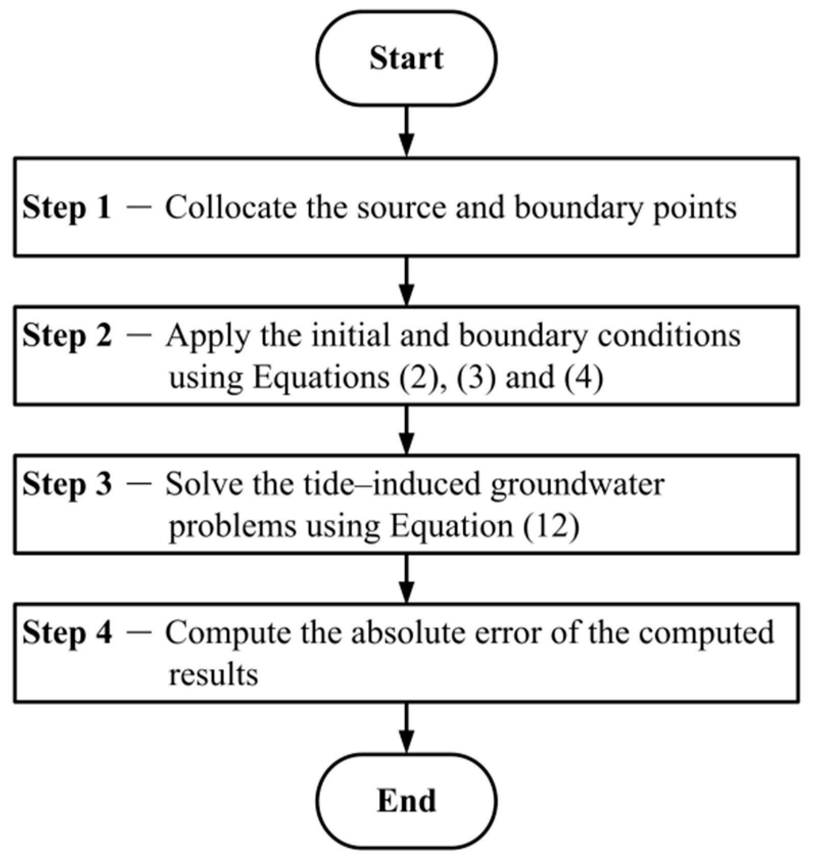
are the boundary point number in time and space domain, respectively. The unknown coefficients are evaluated for solving Equation (13). To evaluate the tide–induced groundwater response, the inner points must be collocated in the spacetime domain. The tide–induced groundwater response at inner points may then be calculated by Equation (13). The schematic diagram for the one–dimensional tide–induced groundwater problems is depicted in
Figure 1.
In this article, we consider a novel spacetime collocation scheme to model the transient tide–induced groundwater problems. On the basis of the spacetime collocation scheme, time is considered to be an independent variable [
30,
31].
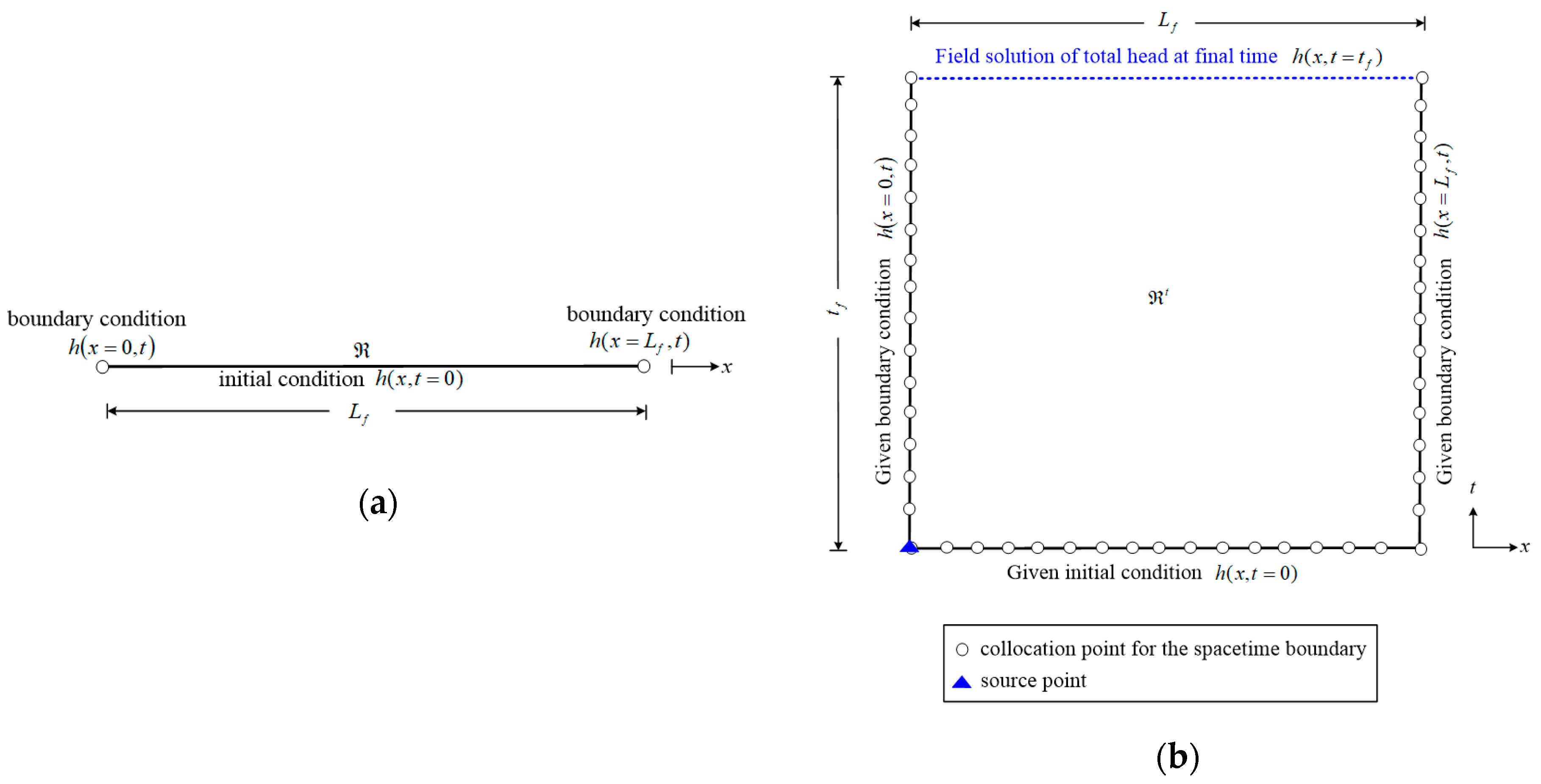
Figure 2a indicates a one-dimensional transient tide–induced groundwater problem. From
Figure 2a,
denotes the space domain,
denotes the space dimension of the problem, and
denotes the total elapsed time. It is clear that this problem is one-dimensional in both time as well as space. As depicted in
Figure 2b, the one-dimensional space domain turns into a two-dimensional spacetime domain. Hence, both initial as well as boundary values are assigned on the spacetime boundaries. Since the inaccessible boundary values are at the final time, the novel proposed scheme may transform the one-dimensional unsteady state tide–induced groundwater problems into inverse BVPs in two-dimensions.
4. Numerical Examples
Five numerical implementations are conducted to investigate the accuracy of the proposed method. The objective of each numerical example is depicted in
Table 1. In numerical examples 1 and 2, we conduct the sensitivity analysis and results comparison with the analytical solution. In the numerical example 3 and 4, we compare the accuracy of the proposed method with that of the time–marching finite difference method (FDM). Furthermore, we consider an application example in numerical example 5, where a time series of real tidal fluctuation data recorded at Xing–Da port by the Ministry of Economic Affairs Water Resources Department are used to study tide–induced groundwater flow problems.
4.1. Numerical Example 1
Since our numerical method is established from the CTM, the correctness of the numerical solutions may depend on the terms of the Trefftz functions. Hence, a sensitivity study is conducted. The governing equation of one–dimensional tide–induced groundwater response in a confined aquifer is described as Equation (1). The data of the boundary are assigned by adopting the following analytical solution.
Figure 2a depicts the configuration of the one–dimensional tide–induced groundwater problem. The space dimension of the problem (
) is 1000 m. The transmissivity (
T) is 1800 m
2/hr. The storage coefficient (
S) is
. The leakage coefficient (
L) is 0.12/d. The elapsed time (
) is 120 hr. The numbers of the boundary and source points in this example are considered to be 150 and one. The initial data are provided on the bottom spacetime region. As for the boundary data, it is assigned on both right and left of the spacetime region, as illustrated in
Figure 2. To evaluate the accuracy of the proposed approach, the maximum absolute error (MAE) is evaluated by the following equation [
32,
33,
34].
where
denotes the exact solution and
denotes the numerical solution.
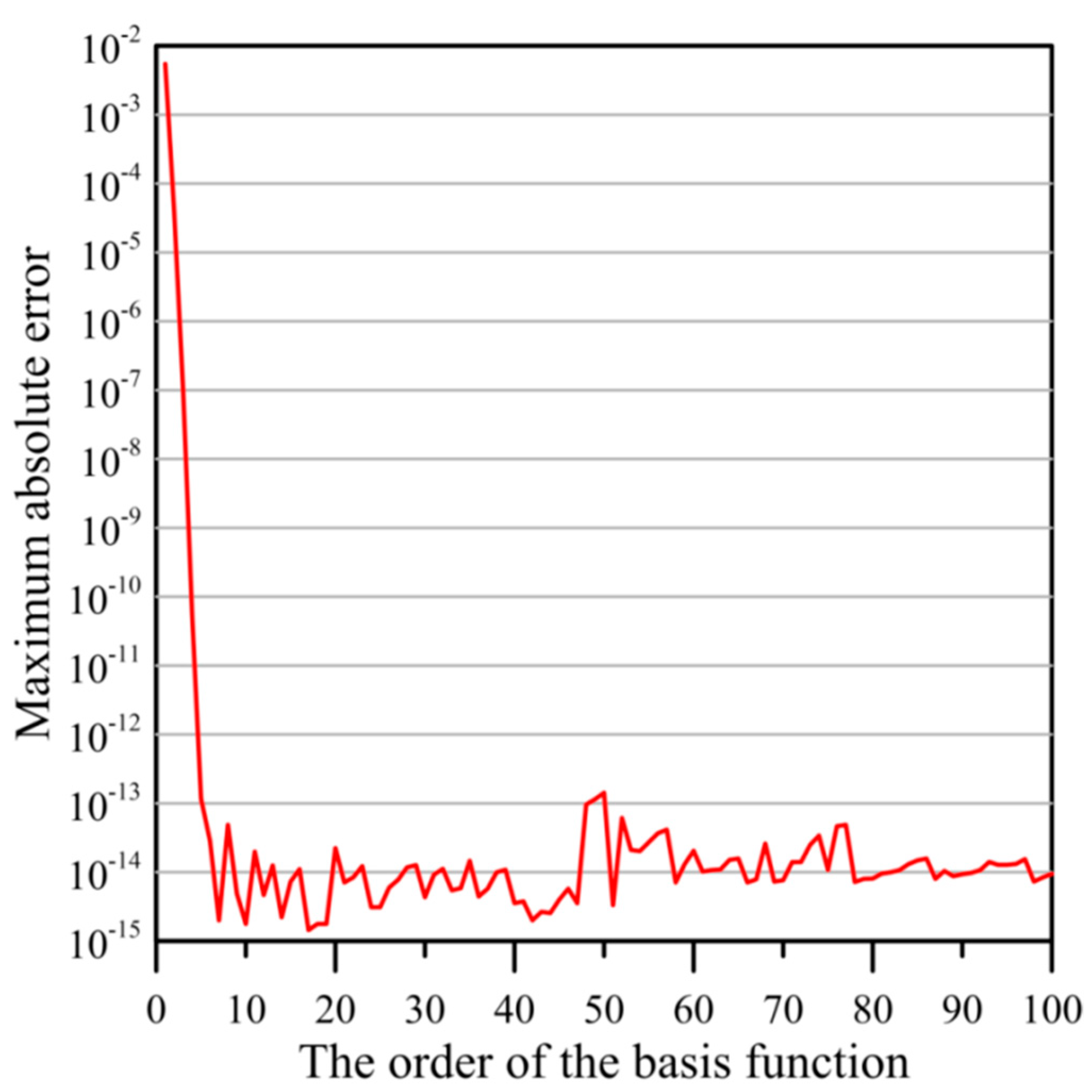
Figure 3 demonstrates the terms of the basis function versus the MAE. It seems that the computed results with high accuracy may be obtained when the terms of the basis function is greater than 10. To further investigate the accuracy of the SCA, we consider another problem. The governing equation can be described as Equation (1). The initial condition is described as
The right, as well as left boundary conditions are described as
The analytical solution is given as
The space dimension of the problem is 5000 m. The transmissivity is 1.25 m
2/hr. The storage coefficient is
. The leakage coefficient is
/d. The elapsed time is 5 hr. The schematic illustration is shown in
Figure 2a. The initial and boundary values are provided on the lateral and bottom of the spacetime region, as displayed in
Figure 2b. There exist one source point and 153 boundary points. We consider the terms of the basis function to be 10. To yield the field solution, we consider 2601 inner points distributed in the spacetime domain.
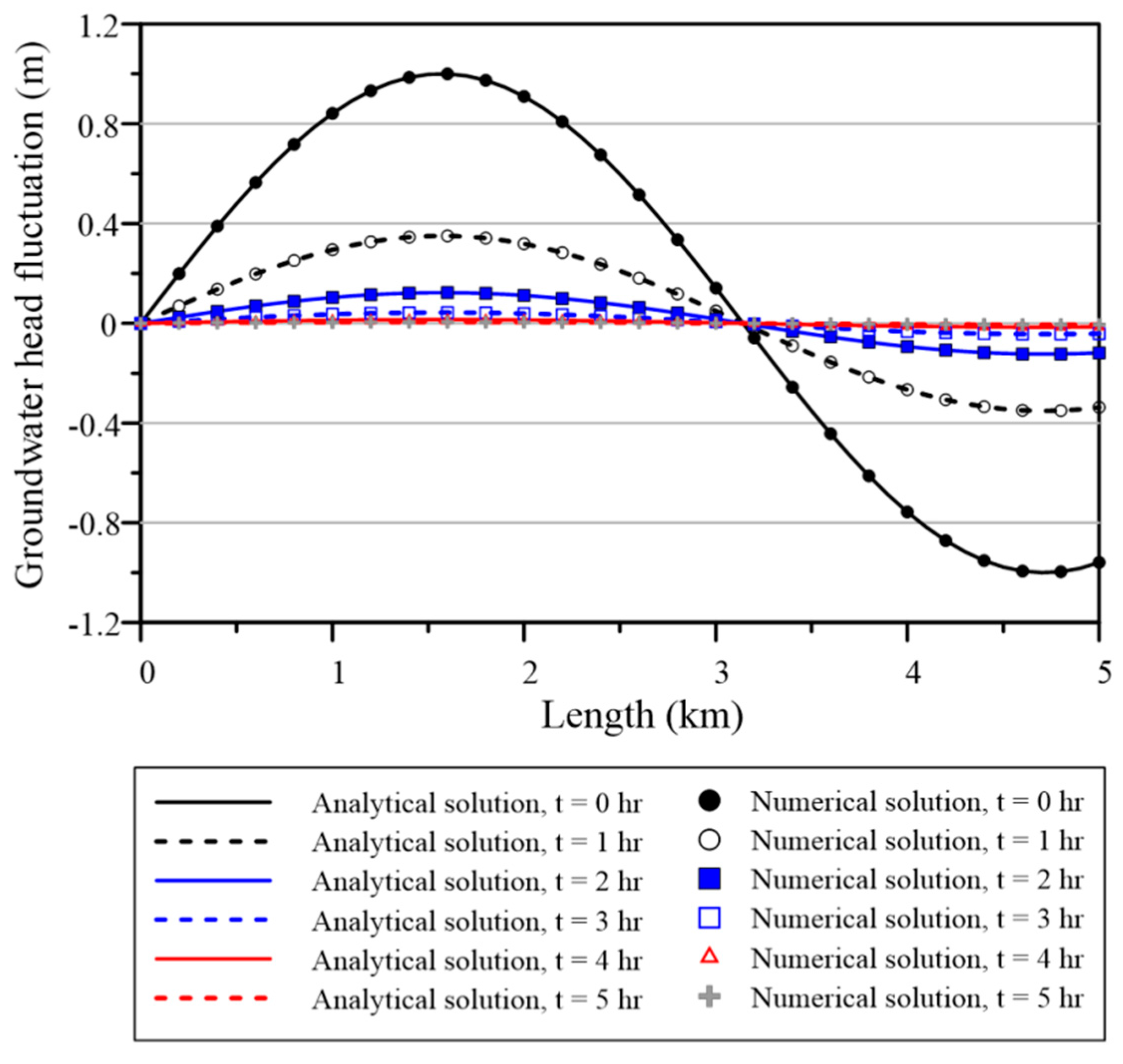
Figure 4 depicts the computed results with the exact solution. It seems that the computed groundwater head fluctuation using the SCA may closely agree with the analytical solution.
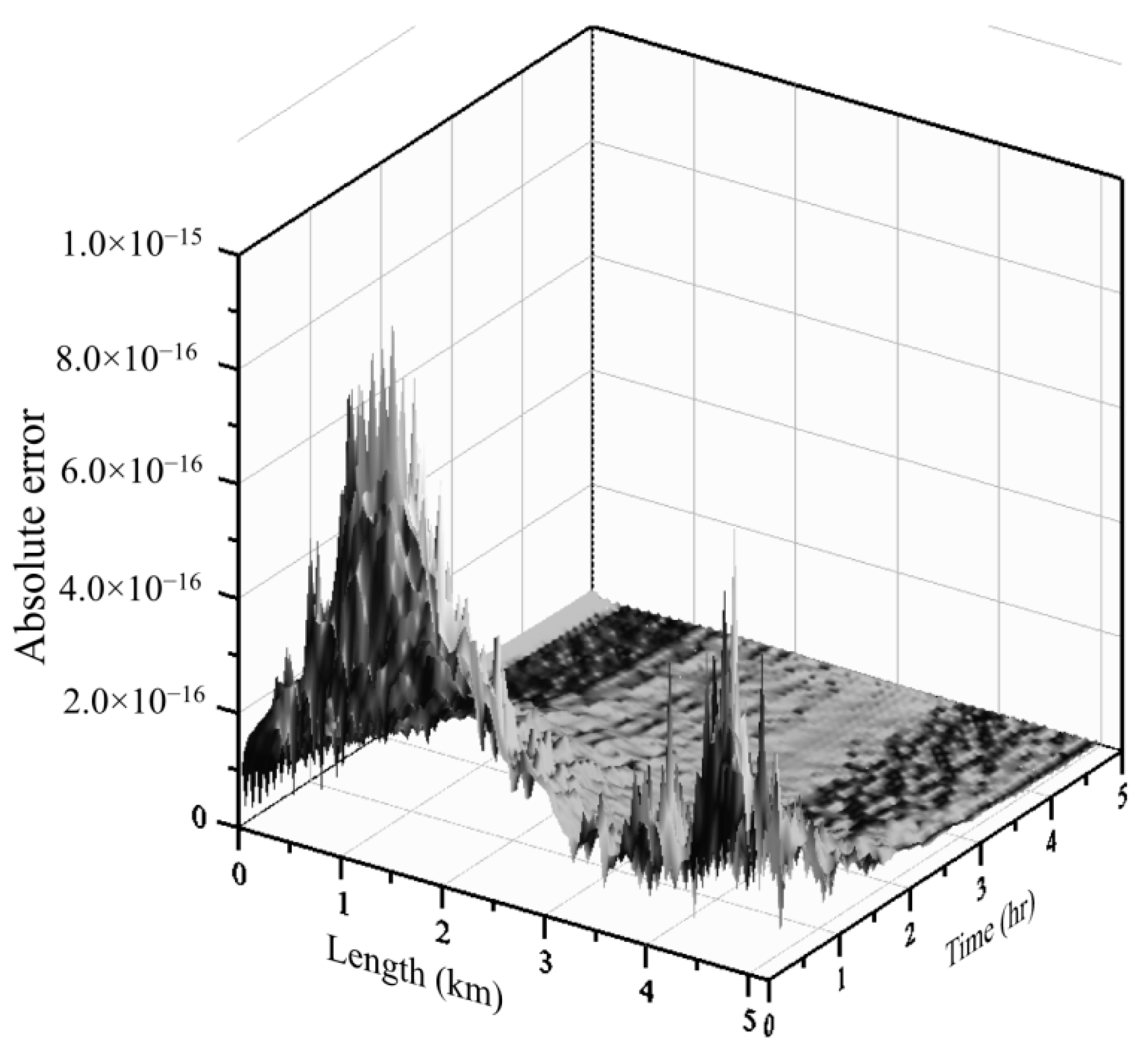
Figure 5 shows the correctness for the SCA. The MAE associated with the SCA is of the order of
. It is obvious that the SCA may acquire highly accurate results.
4.2. Numerical Example 2
The governing equation of the numerical example 2 is given as Equation (1). The left boundary data are described as Equation (19). We consider the right boundary to be
The exact solution is found as
Figure 2a depicts the configuration of the one–dimensional tide–induced groundwater problem. The dimension of the space domain, the transmissivity, the storage coefficient, the leakage coefficient, and the elapsed time are considered to be 5000 m, 1.25 m
2/hr,
,
/d and 5 hr, respectively. The boundary and initial data are given on the lateral and bottom of the spacetime domain, as shown in
Figure 2b. We place a source point and 153 boundary points uniformly distributed on the boundary. The Dirichlet and Neumann boundary data are assigned on boundary points. We consider the order of the basis function to be 10. To yield the field solution, we collocate 2601 inner points.
Figure 6 indicates the computed and the exact solutions. From
Figure 6, the computed tide–induced groundwater fluctuations may be completely consistent with the exact solution.
Figure 7 shows the correctness for the SCA. Using the SCA, the MAE is of the order of
. It is obvious that the SCA can acquire high accuracy performance.
4.3. Numerical Example 3
The governing equation of numerical example 3 is represented by Equation (1). For this example, two cases with different initial hydraulic heads are considered.
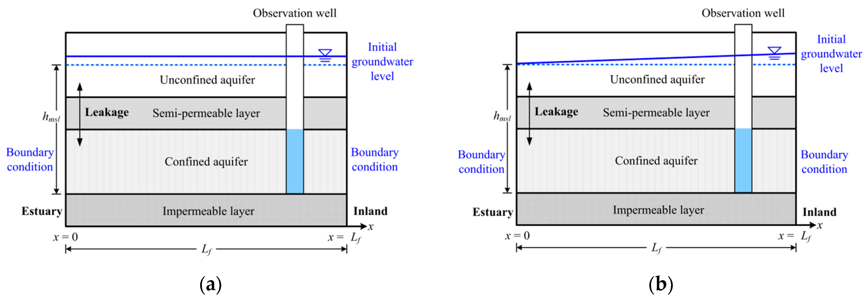
Figure 8 illustrates the schematic of finite confined coastal aquifers. In Case A, the initial groundwater level is considered to be constant,
, as indicated in
Figure 8a. In Case B, the initial head is considered to be
, where
denotes the head of the seaside,
a denotes the gradient of the hydraulic head in the seaside, and
denotes the averaged mean sea level. As shown in
Figure 8b, the groundwater head may linearly increase as the distance from coastline increases.
4.3.1. Case A: Constant Initial Hydraulic Head
In Case A, the initial groundwater level is considered to be constant as follows.
The left tidal boundary data are
The boundary data on the inland side is described as
Equation (26) describes that the tide has nearly no effect if
x approaches far inland. The length is 3000 m. The transmissivity is 31.25 m
2/hr. The storage coefficient is
. The leakage coefficient is
/d. The elapsed time is 65 hr. The amplitude of the tidal change (
A) is 2.5 m. The tidal period (
t0) is 24.7 hr. The schematic illustration for case A is shown in
Figure 8a.
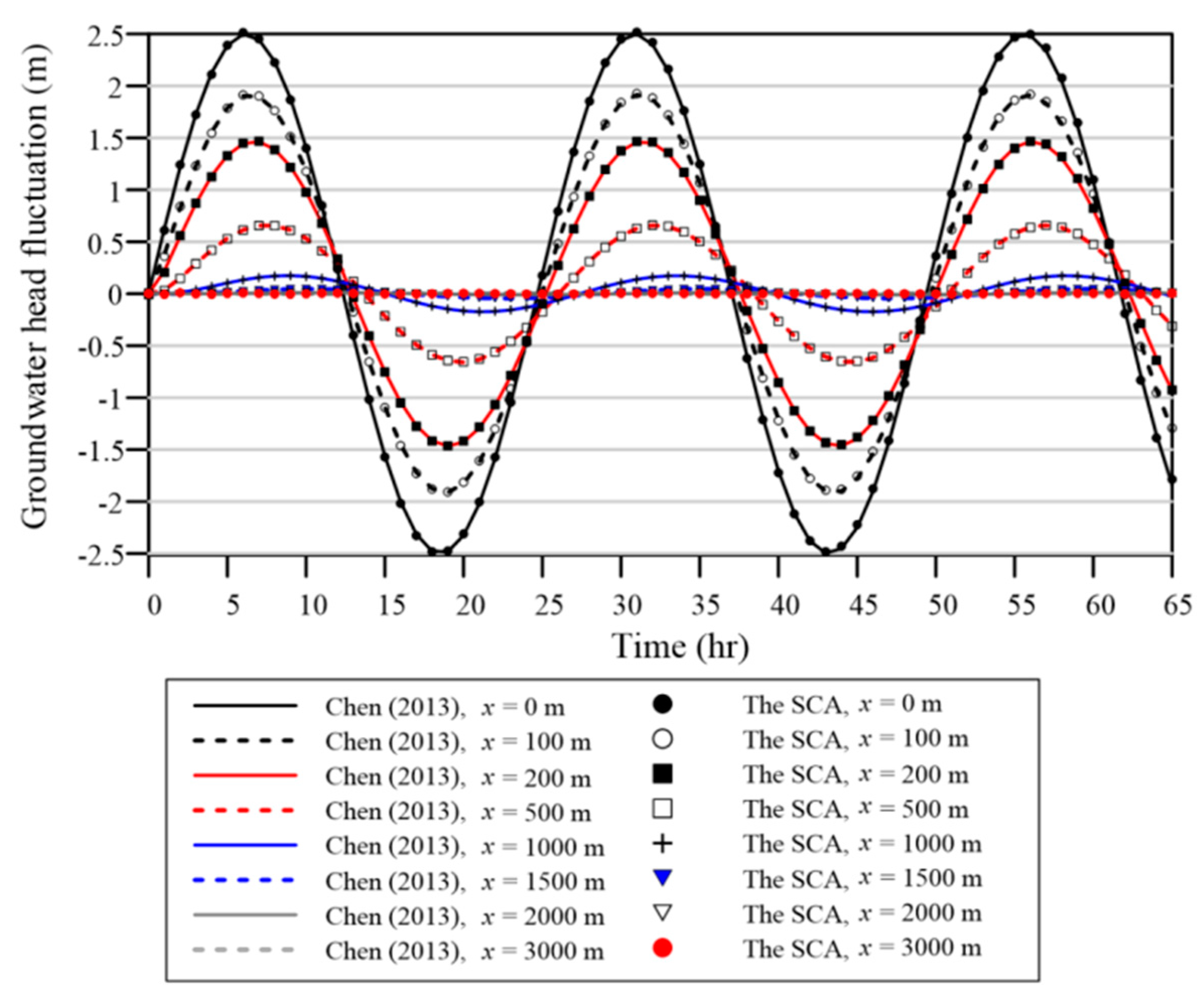
Chen et al. (2013) applied the FDM to solve this problem [
35]. To apply the FDM, discretization in the spatial and temporal domains were separately considered. For spatial discretization, the governing equation of one-dimensional tide–induced groundwater response for each grid point was approximated using backward difference formulas. For time discretization, the implicit scheme was adopted [
35]. Since the proposed method is one of the meshfree approaches, this problem is solved by using the boundary points placed on the spacetime boundary. Therefore, we assign one source point and 163 boundary points uniformly distributed on the boundary. The boundary data are provided on boundary points. We consider the order of the basis function to be 25. To obtain the field solution, we collocate 2046 inner points. The numerical result of our method is then compared with that of the FDM.
Figure 9 shows the numerical results adopting the FDM and our method. It is found that the tide–induced groundwater fluctuations computed using our method agreed well with those of the FDM.
4.3.2. Case B: Inclined Initial Hydraulic Head
In Case B, the head of the seaside is a function of distance
x. The initial head is given as
The boundary conditions at both left and right sides are given as
In this example,
, and
. Other parameters including the dimension of the space domain, the transmissivity, the storage coefficient, the leakage coefficient, the elapsed time, the amplitude of the tidal change, and the tidal period are the same as Case A. The schematic illustration for Case A is shown in
Figure 8b.
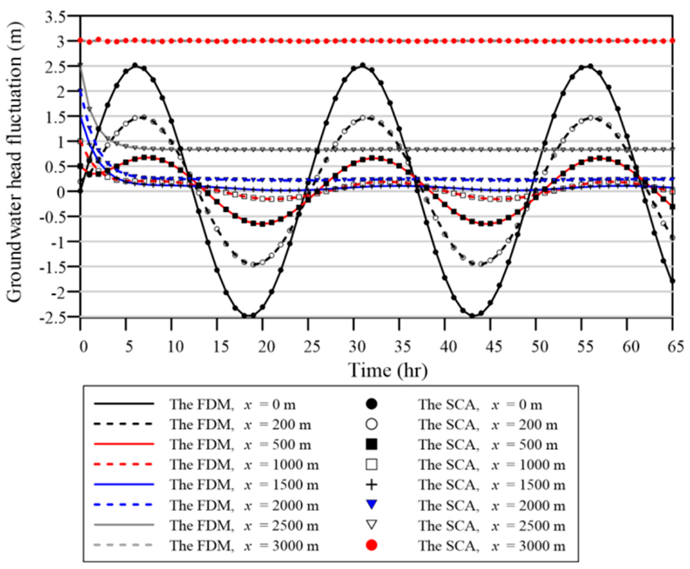
This example is solved using both FDM and our method. For the FDM analysis, the temporal and spatial discretizations for this problem are separately considered. The implicit scheme and the central difference approximation are considered for the temporal and spatial discretization, respectively. For the SCA analysis, we consider a source point and 163 boundary points. We consider the basis function order to be 25.
Figure 10 depicts the results computed utilizing the FDM and our method. It is found that the tide–induced groundwater response computed using the proposed method agreed well with those of the FDM.
4.4. Numerical Example 4
The governing equation of the numerical example 4 is given as Equation (1). The initial condition is given as Equation (24). The left tidal boundary head is given as
The boundary head on the inland side is described as
The analytical solution [
36] is found as
Figure 8a depicts the schematic illustration of the one-dimensional tide-induced groundwater problem. The dimension of the length is 3000 m. The transmissivity is 2000 m
2/d. The storage coefficient is
. The amplitude of the tidal change is 0.65 m. The tidal period is 24 hr. The leakage coefficient is considered to be 0/d. The total elapsed time is considered to be 3 hr.
For the SCA analysis, we consider 183 boundary points and one source point. We consider the basis function order for the analysis to be 15. We also collocate 3721 inner points for the validation.
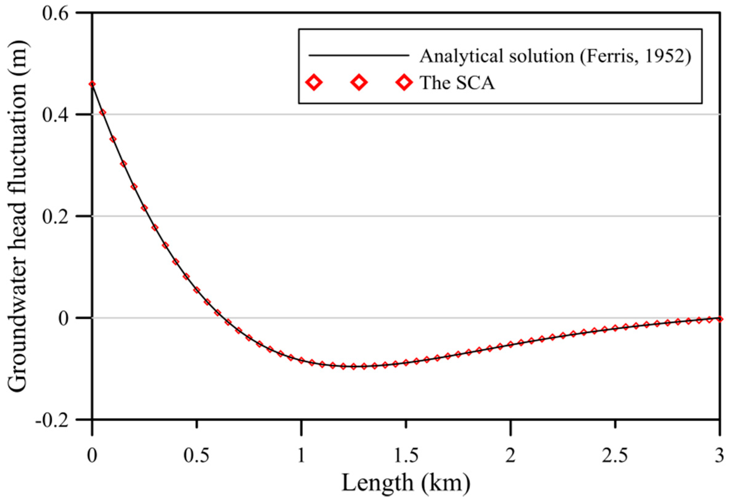
Figure 11 indicates the computed and exact solutions [
36]. From
Figure 11, the computed tide–induced groundwater fluctuations are consistent with the exact solution. Using the SCA, the MAE is of the order of
. It is obvious that the SCA can acquire high accuracy performance.
To further illustrate the correctness of the computed tide–induced head fluctuations from the proposed SCA and that from the conventional time–marching FDM, we conduct a comparison example in numerical example 4. The governing equation is represented by Equation (1). The initial condition is given as Equation (24). The left tidal boundary head is given as
The boundary data on the inland side is described as
The analytical solution is obtained as follows.
Figure 8a depicts the schematic illustration of the one–dimensional tide–induced groundwater problem. The dimension of the length is 3000 m. The transmissivity is 2000 m
2/d. The storage coefficient is
. The amplitude of the tidal change is 0.65 m. The tidal period is 24 h. The leakage coefficient is considered to be 0, 0.01, and 0.05/d. Therefore, the amplitude of groundwater head is calculated for different leakage coefficient. The total elapsed time is considered to be 3 and 6 hr.
This example is solved utilizing both FDM and SCA. For the FDM analysis, the implicit scheme and the central difference approximation are considered for the temporal and spatial discretization, respectively. For the SCA analysis, we consider 183 boundary points and one source point. We consider the basis function order for the analysis to be 15. To obtain the field solution, we collocate 3721 inner points.
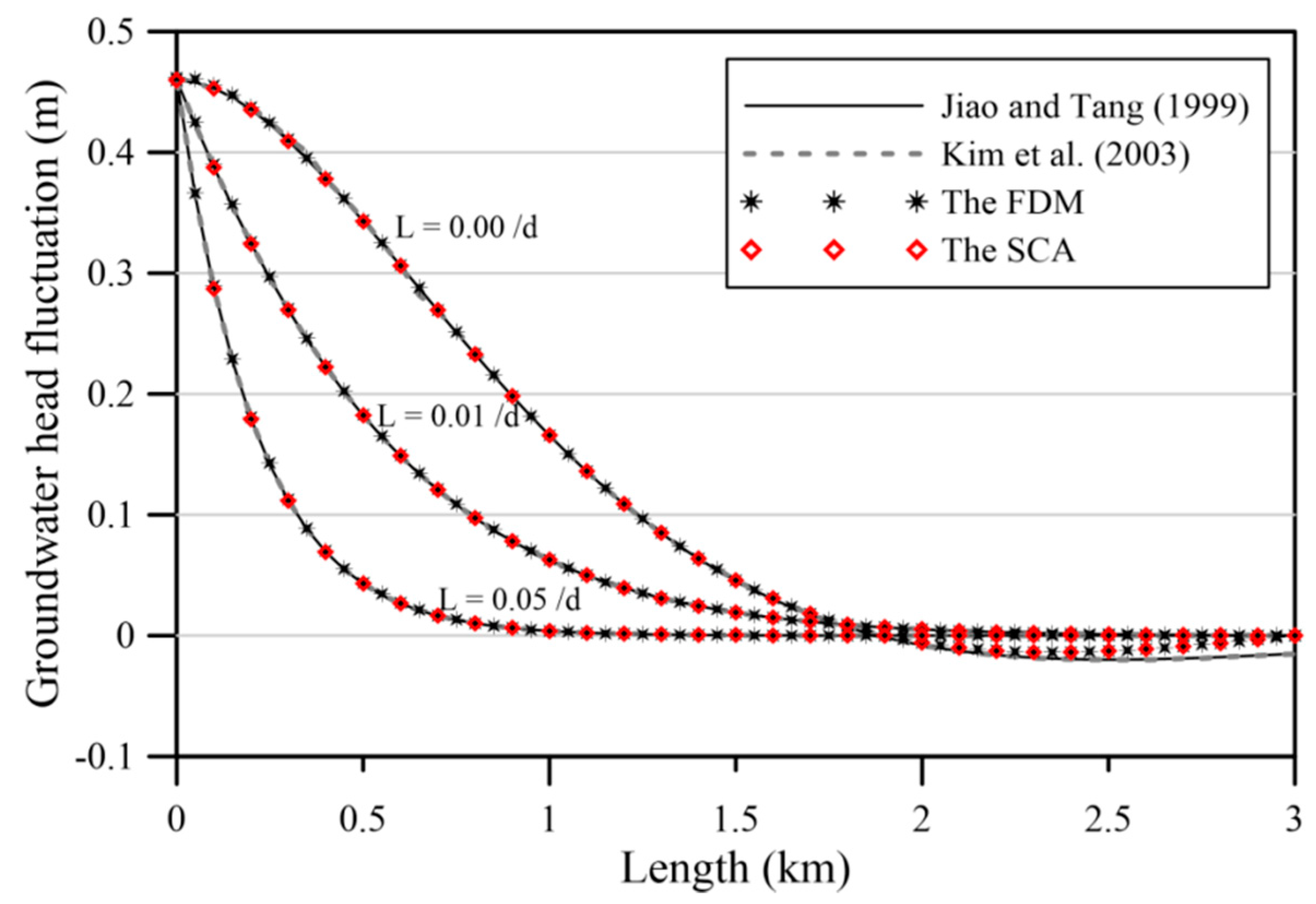
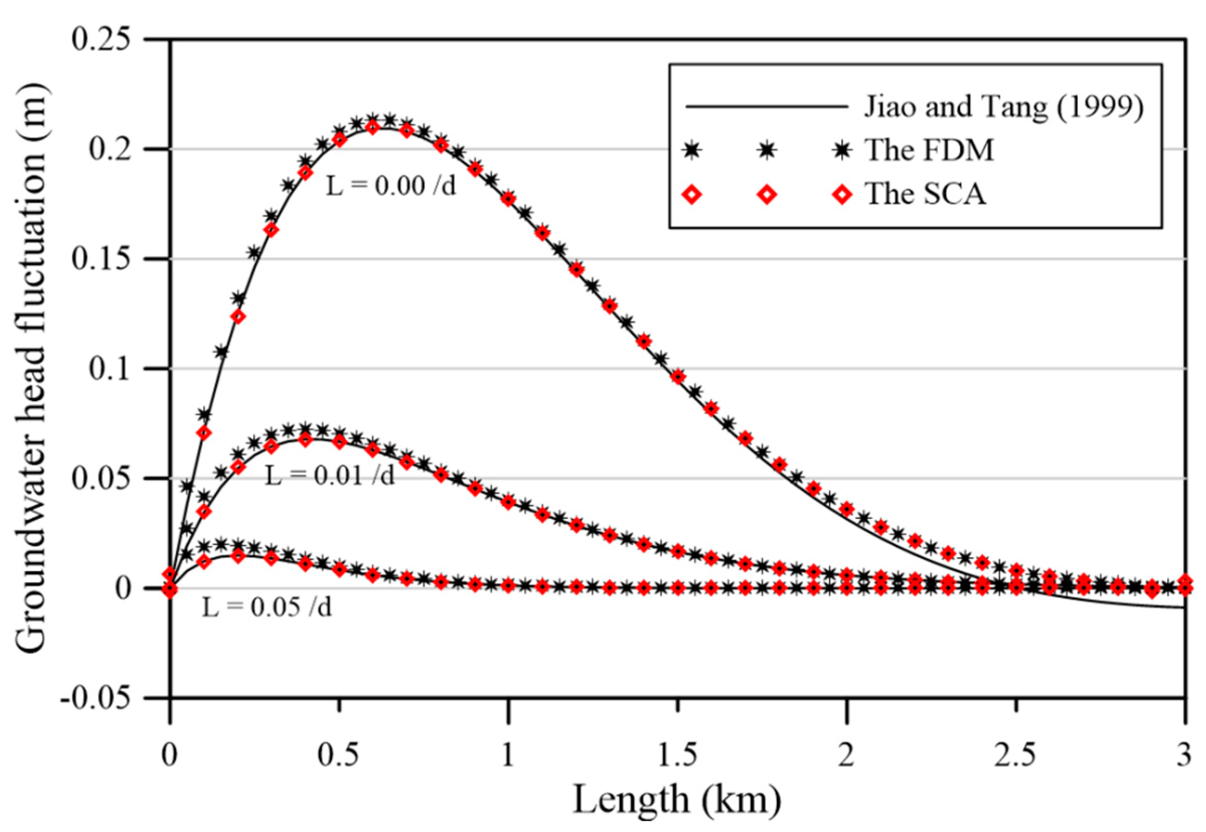
Figure 12 and
Figure 13 depict the computed results from the analytical solution [
13], the Laplace domain solution [
37], the FDM, and our method at
and
, respectively. It is found that the computed results of tide–induced groundwater fluctuations using our method closely agree with the analytical solution.
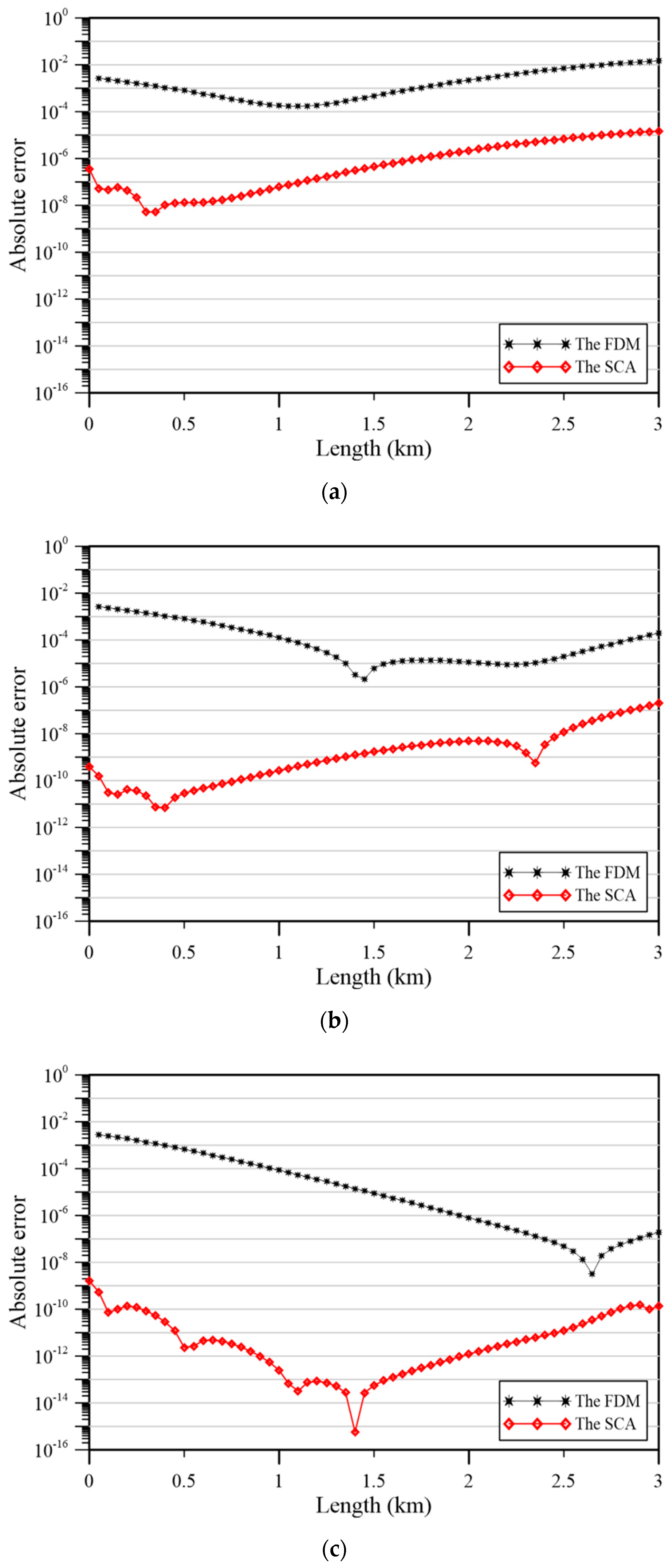
Figure 14 demonstrates the comparison of the accuracy with the FDM and the proposed method
with the consideration of different leakage coefficient. We, therefore, compare the absolute error of our approach and those of the FDM. From
Figure 14, the MAE of the FDM is only of the order of
and
. However, the MAE of our approach may reach up to the order of
, as displayed in
Figure 14.
Table 2 shows the accuracy of our method with those of the conventional time-stepping approach using the FDM with the consideration of different leakage coefficient. From
Table 2, it is found that the MAE remains in the order of
to
. It is obvious that great agreement by the proposed method may be achieved.
4.5. Numerical Example 5
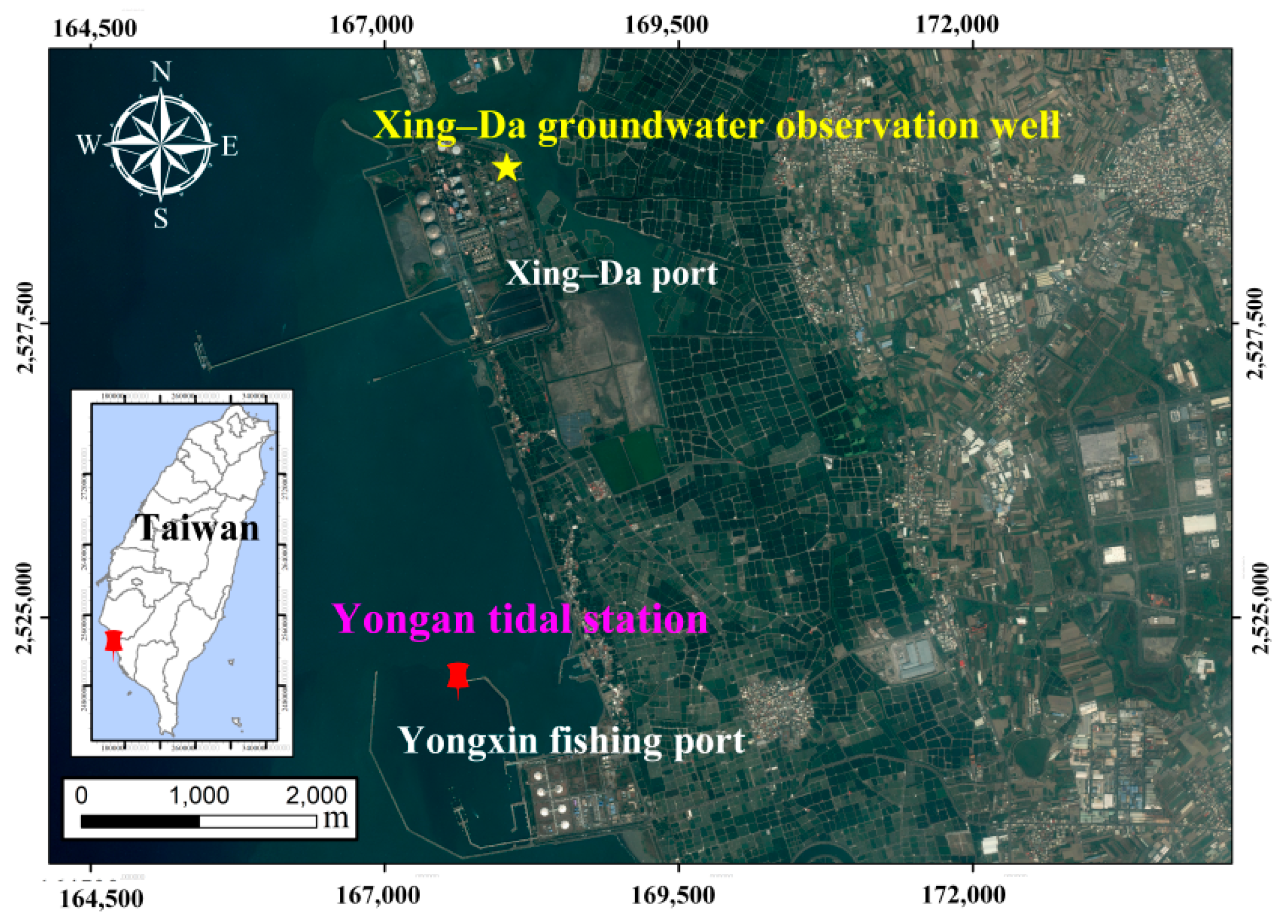
Previous examples illustrate that our method is appropriately validated using the harmonic boundary conditions. Since the tidal variation is probably the major trigger inducing groundwater level fluctuation in coastal aquifers, the tidal fluctuation data are used to study tide–induced groundwater flow problems. This example is to evaluate the tidal and piezometer data at the Xing–Da port, Kaohsiung, Taiwan. The Xing–Da port is located in the Kaohsiung, southwestern Taiwan, as shown in
Figure 15. The tidal data was from Yongan tidal station at 22°49′08.00″ N latitude and 120°11′51.00″ E longitude. The piezometer data was from Xing–Da groundwater observation well at 22°51′30.52″ N latitude and 120°12′04.77″ E longitude [
38].
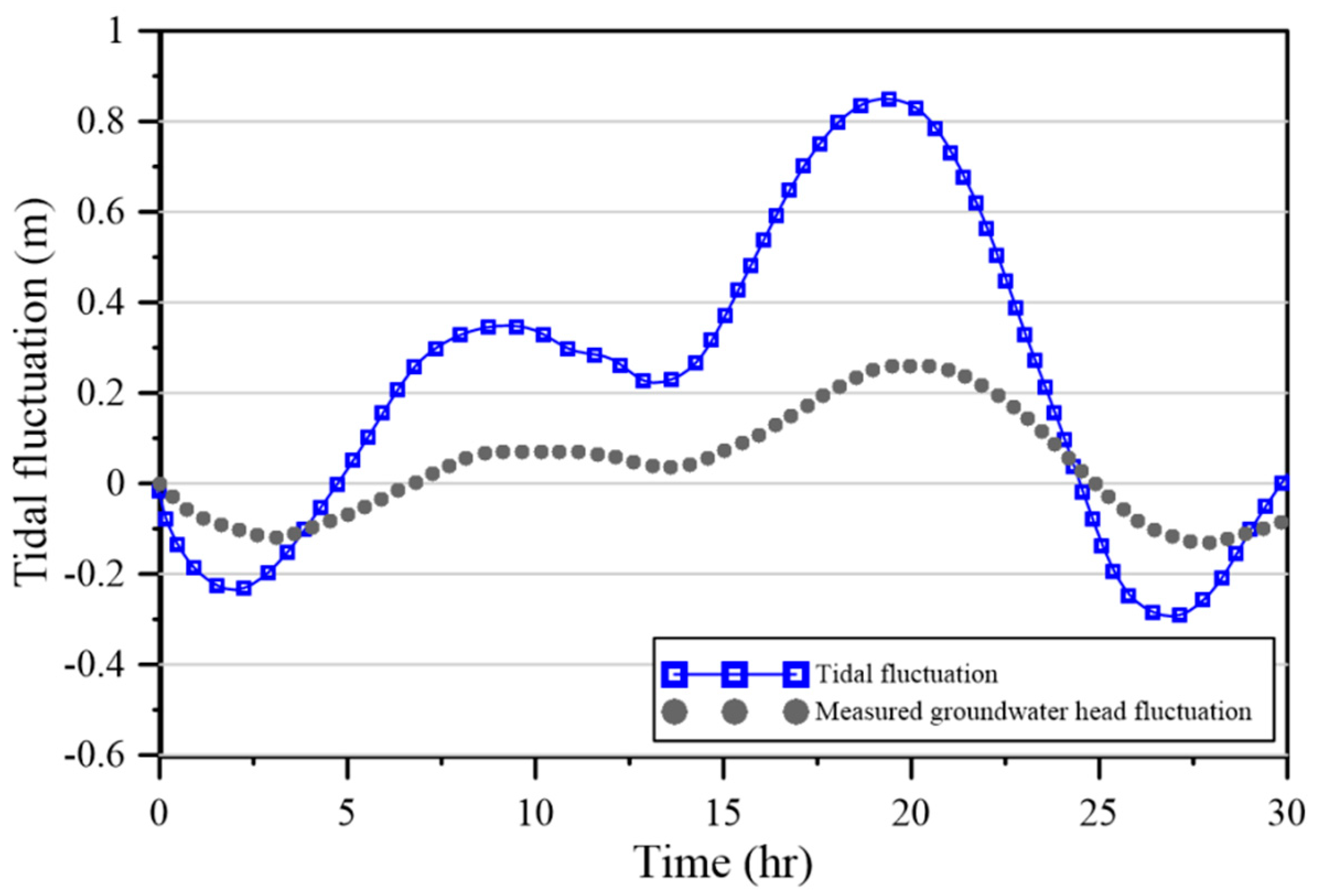
The initial head is described as Equation (24). This study analyzed the tidal fluctuation data recorded at Xing–Da port from 00:00 p.m. on 22 December to 06:00 a.m. on 23 December 2018, by the Ministry of Economic Affairs Water Resources Department, as shown in
Figure 16. It is found that the highest hourly tidal fluctuation reached 0.85 m, whereas the lowest hourly tidal fluctuation may reach −0.29 m. Hence, the left tidal boundary condition is described as
where
denotes the measured data by the Water Resources Agency, Ministry of Economic Affairs [
38], as shown in
Figure 16. The boundary head on the inland is described as
According to the Engineering Geological Investigation Data Bank by the Central Geology Survey of the Ministry of Economic Affairs [
38], the property of the confined aquifer and semi-permeable layers are sand and silt, respectively.
Figure 17 shows the schematic of the numerical example 5. The thickness of the confined aquifer and semi-permeable layer are 65 m and 15 m, as shown in
Figure 17. The parameters used are listed in
Table 3. From
Table 3, the permeability of the confined aquifer and semi-permeable layer are 2 × 10
−3 cm/s and 10
−5 cm/s. The transmissivity is 4.68 m
2/h. The storage coefficient is
. The leakage coefficient is
/d. The dimension of the length is 3000 m. The final elapsed time is 30 hr. The amplitude of the tidal change is 1 m. The tidal period is 24 h.
We consider 663 boundary points and a source point. The basis function order for the analysis is 15. To obtain the tide–induced groundwater fluctuation, we collocate 18,631 inner points.
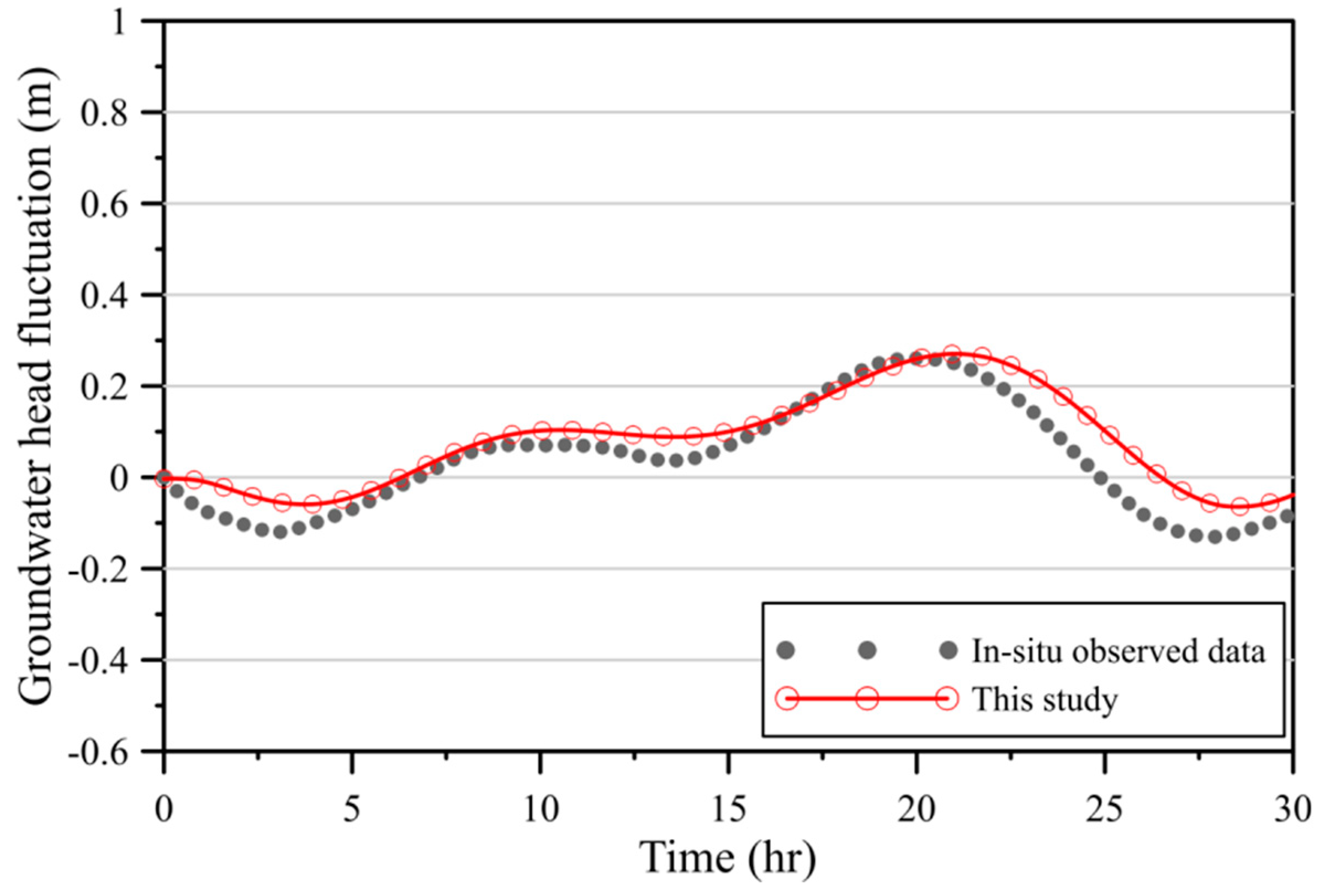
Figure 18 demonstrates the comparison of measured data with the computed groundwater fluctuation using our method at
m. Red line denotes the computed numerical results and the gray square denotes the measured data. It is found that the computed results of the tide–induced groundwater head using the proposed method may agree with the measured data. Although there may be a shift in time in
Figure 18, the overall behavior of the tide–induced groundwater head may be captured using our proposed method.
5. Discussion
To investigate the proposed method, five numerical examples are conducted. Based on the results, the discussions are carried out as follows.
We conduct the sensitivity analysis and results compared with the analytical solution in example 1 and example 2. Results obtained demonstrate that the MAE is in the order of . It is obvious that the SCA may yield highly accurate results. To further illustrate the advantages of the proposed approach, examples 3 and 4 are conducted to investigate the accuracy of temporal discretization. From the results of this study, we indicate that the MAE of the SCA remains in the order of to . We also compare the MAE of our method and those of the FDM. The MAE of the FDM is only on the order of and . It is significant that the proposed method may have more accurate numerical results than those of the conventional time–marching FDM.
We propose the spacetime collocation approach for solving the tide–induced groundwater response. For the solving of the tide–induced groundwater response in a coastal confined aquifer with an estuary tidal–loading boundary using the proposed method, the boundary points are placed in the spacetime region. Hence, both initial as well as boundary values are considered as boundary conditions on the spacetime boundaries. The one–dimensional initial value problem can then be regarded as a two–dimensional inverse BVP. Accordingly, the transient problems for tide-induced head response in a coastal confined aquifer may be solved without utilizing the time-stepping techniques. Besides, more accurate numerical results for solving transient problems can be obtained.
However, the SCA has to derive the general solutions as the basis functions for the governing equation of one–dimensional tide–induced groundwater response in a coastal confined aquifer utilizing the separation of variables. The solutions of the tide–induced head response are then described as a series adopting the addition theorem. As a result, the proposed technique can only deal with the linear governing equation.
Furthermore, another disadvantage is that the transformation of the original one–dimensional problem into two–dimensional spacetime boundary value problem may increase the volume of computing. Because the proposed technique is a boundary–type method, the points may be collocated only on the spacetime boundary of the domain. Since we do not need to place any collocation points inside the domain, the proposed method may be more efficient than other numerical approaches. Although the array of the computation from two–dimensional spacetime boundary value problem may be larger than the original one–dimensional problem, it is found that the benefits of the compromise for increasing the volume of the computation to obtain highly accurate results for tide–induced groundwater flow problem may be acceptable.
In addition, similar to other boundary-type meshless methods, the proposed method may also suffer from the numerical instability due to the ill-posed phenomenon of the meshless method for solving two- or three-dimensional problems.
6. Conclusions
The spacetime collocation approach for solving the tide–induced groundwater response has been proposed. We carried out numerical problems to verify our method. The comparison of the results and accuracy for the spacetime collocation approach (SCA) with the time–marching finite difference method is carried out. The findings and contributions of this study are addressed. Furthermore, the SCA is adopted to evaluate the tidal and groundwater piezometer data at the Xing–Da port, Kaohsiung, Taiwan.
The results from numerical examples depict that the SCA may obtain highly accurate results comparing to other numerical methods. Besides, the proposed method demonstrates the advantage of the SCA that we only discretize by a set of points on the spacetime boundary without tedious mesh generation. Hence, it may significantly enhance the applicability.
