Article

Variable Guide Vane Scheduling Method Based on the Kinematic Model and Dual Schedule Curves

The 4th R&D Institute, Agency for Defense Development, Daejeon 34186, Korea
*
Author to whom correspondence should be addressed.
Deceased author.
Appl. Sci. 2020, 10(19), 6643; https://doi.org/10.3390/app10196643
Submission received: 8 September 2020 / Revised: 19 September 2020 / Accepted: 20 September 2020 / Published: 23 September 2020
(This article belongs to the Section Mechanical Engineering)

Abstract

:
The variable guide vanes (VGV) of gas turbine engines are commonly utilized to expand operating range and to improve efficiency of the compressor. Guiding air flow using the VGVs in the compressor prevents aerodynamic instability by making proper incidence angle to the blades. In this study, we dealt with rig-type three-stages VGVs for developed engine tests. The three link mechanism of VGVs are linked to each other with two hydraulic actuators, and inevitably, induced hysteresis exists between vane rotations and actuators strokes, due to links with non-fully constrained degree of freedoms for easy installation and instrumentation, as well. Therefore, the adjustment of each VGVs link mechanism is required to satisfy vane angle demands. To adjust coupled three-stages VGVs link mechanism, an analytical VGV-link kinematic model was derived, and effects of two adjusting parameters (lengths of bell cranks and vertical links) were discovered. Lastly, we obtained two vane angle schedule curves from the experiments according to link moving directions, and applied them to the engine controller to minimize hysteresis of the variable inlet guide vane (VIGV). The proposed VGV adjusting and controlling method can be simply applied to the pre-designed or pre-manufactured VGVs system without mechanical compensation or additional cost.

1. Introduction

Aerodynamic stability should be assured for the compressor of an aircraft gas-turbine engine, not only at the operating design point, but also at off-design points, due to its wide operating range with frequent acceleration and deceleration. Any mismatch in the angles of inlet air-flow of the compressor and stator vane leads to flow separation and reduces the effective air-flow area. Moreover, aerodynamic instability such as surge or stall might appear, and these could lead to severe structural damage to the engine.
Variable guide vanes (VGVs) are therefore generally utilized to obtain stability of the compressor over a wide operating range and the stator vanes of VGVs change their angles according to the inlet air-flow, which varies with the engine RPM [1,2]. In the case of a centrifugal type compressor, inlet guide vanes (IGV) in front of the impeller and radial gap between impeller blade tip and diffuser leading edge are manipulated by using actuators and variable geometries [3,4,5,6]. In the case of axial type compressors, comparatively large numbers of vanes and multiple vane stages are needed. Thus unique actuation link mechanism is required to manipulate multiple vane stages, simultaneously [7,8,9].
The actuation link mechanism generally consists of actuators, links, a unison ring, lever arms, and vanes. The unison ring is connected to links, and rotates vanes about the rotational axis of the vanes via lever arms (shown in Figure 1). The links positioned between the actuators and unison-ring, transform linear extensional and compressional motion of the actuators into the rotational motion of the unison ring. There are a variety of link structures according to engine size, actuator type, and operational range of the vanes. Thus, analysis of the link mechanisms should be performed to define the actuator requirements: such as stroke or load capacity, and the precise vane and actuator control logic should be also needed to obtain exact angles of vanes according to VGV schedule. However, most of studies focused on the effect of the misaligned vane angle on the compressor performance and the fault diagnosis of the compressor [10,11,12,13,14]. Compared to that, precise control and compensation methods for mechanical drifting or hysteresis of the VGVs link mechanisms have still been rarely studied. Due to the limitations of previous references, this study was performed to obtain solutions for precise VGV control.
Link mechanisms are usually designed with redundancy degrees of freedoms (DOFs) in three-dimensional space to produce well, the rotational motion of lever arms from the linear motion of actuators. With this redundancy DOF, manufacturing tolerance, wearing of actuation link mechanism, and loosening of bolts cause drifting from the vane schedule and hysteresis between the actuator strokes and vane angles [10,12]. To compensate this hysteresis additional mechanical compensations are needed to the VGV link mechanisms such as pre-loading springs or flexible bushings. However, they produce unpredictable friction forces and need a complicated design [15].
In this research, we dealt with a rig-type multiple-stages VGV system which was developed for testing gas-turbine engines. This VGV system has unique link mechanism with three stages of VGV and two hydraulic actuators. For easy instrumentation, it has long vertical link as shown in Figure 1, thus we should investigate the VGV link mechanism to reduce its mechanical hysteresis. Actuator stroke schedule should be presented with considering its coupling linkage motions between two actuators and three stages of VGV. In this respect, we propose novel and simple solution to adjust links and to reduce the hysteresis by analyzing link mechanism and by modifying only control software without mechanical compensations.
In Section 2, the link mechanisms of the newly developed VGV system are described, and their coupled kinematics and inevitable hysteresis of the links are explained. In Section 3, an analytical model that reveals relations between the actuator strokes and vane angles is derived from analysis of the link mechanism, and the methodology for adjusting the link mechanisms is proposed to obtain the desired VGV schedule. The control algorithm based on dual schedule curves is presented to reduce the hysteresis of a variable inlet guide vane (VIGV) in Section 4. Finally, the application test results are presented in Section 5. A summary and conclusions follow in Section 6.

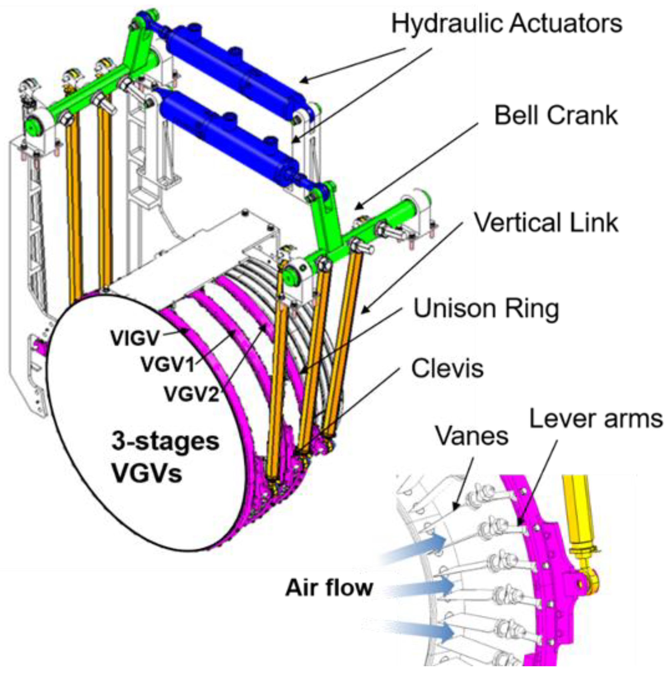
2. Mechanical Structure of the VGVS

2.1. Component of the Link Mechanisms

The axial compressor to be tested consisted of three VGV stages: the VIGV, VGV1 (first-stage variable guide vane), and VGV2 (second-stage variable guide vane), as shown in Figure 1. Three-stage VGVs are connected to the each unison rings through lever arms, and the lever arms and vanes rotate, while the unison ring rotates about the center of the engine. In this research, enough space between the compressor and the hydraulic actuators was obtained by using long vertical links for easy installation of sensors and other components during the development phase of the engine. The unison rings are manipulated by vertical links of the link mechanisms, and extension/compression of the hydraulic actuators induce rotation of bell cranks and vertical movement of the vertical links. Due to using a common bell crank, the rotational motions of the unison rings of three VGV stages are coupled each other, and each motion can be characterized by lengths of their links.

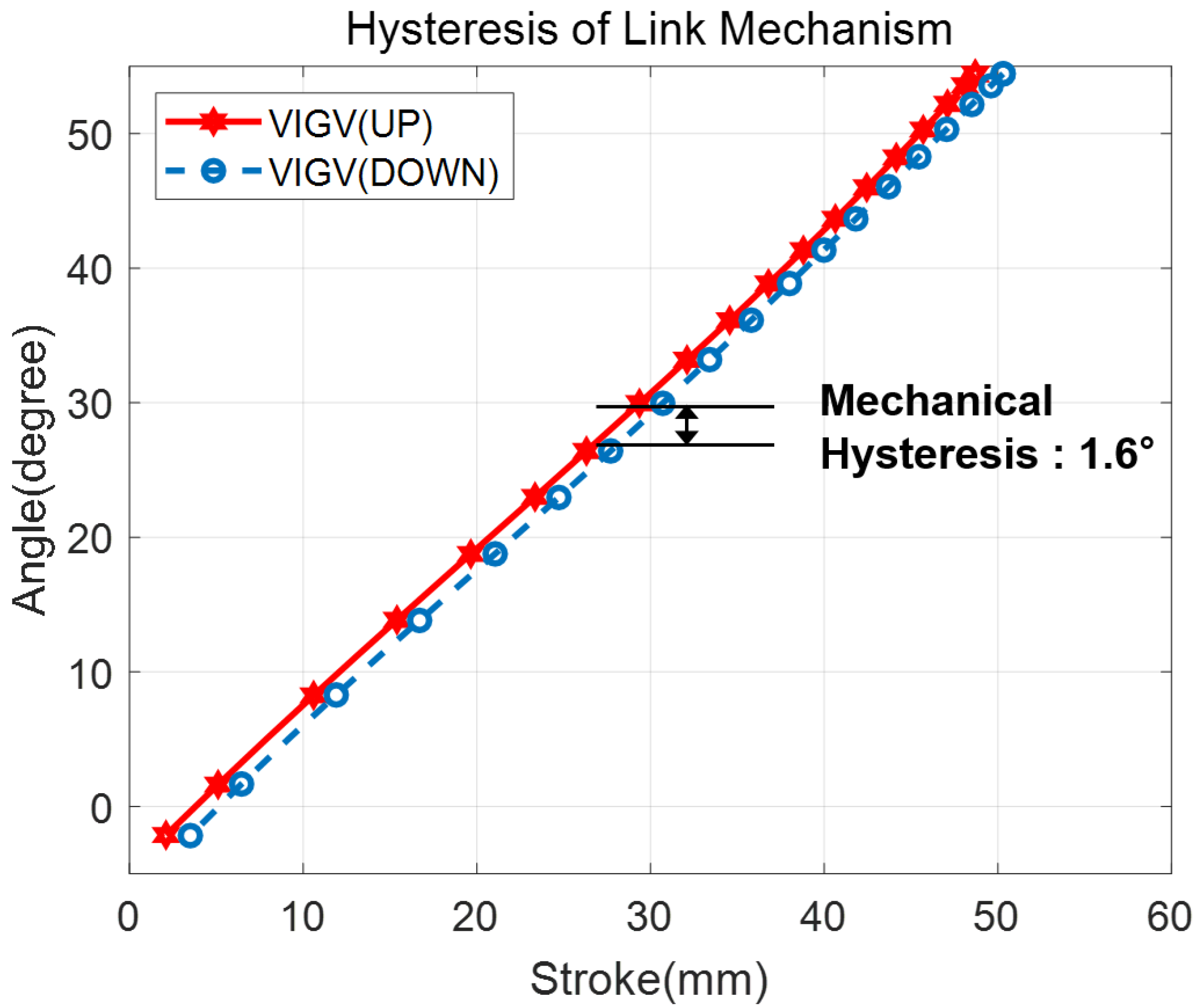
2.2. DOFs and Hysteresis of the VGV Link Mechanisms

Figure 2 shows schematics of link mechanisms and joints representing bell cranks, vertical links, and unison rings of VGVs. There are four links below the bell crank in the mechanisms, including the ground part ( L a ,   L b ,   L c ,   L d ) which are represented in red lines. The DOF of the mechanisms was calculated using the Grubler’s Equation with joints as follows [16].
D O F   =   6 ( N l i n k 1 ) 5 N J 1 4 N J 2 3 N J 3 2 N J 4 N J 5
Here, N l i n k represents the total number of links, N J k represents the number of joints having k DOF. The numbers of joints and links in the link mechanism in Figure 2 are listed in Table 1.
The number of DOF’s calculated using the Grubler’s equation was six. However, two rotational motions of vertical links about their longitudinal axes do not affect the motion of the unison ring motion; thus, the resultant DOF’s number is four (as kinematic redundancy). The kinematic redundancy causes eccentricity of rotation at the center of the unison ring, and inevitably causes the VGV link mechanisms to have hysteresis from the actuator to the unison ring.
For this reason, research about reducing DOF redundancy by modifying the joint type or array have been conducted, and additional springs and bushings to apply a pre-load have been widely used. However, elimination of redundancy and addition of pre-load parts also induces unnecessary frictional forces and increases system complexity.
The proposed methodology in this paper can be applied to the VGVs system to obtain vane angles according to the VGV schedule with minimization of VIGV hysteresis based on the control algorithm with dual schedule curves, as presented in the following sections.

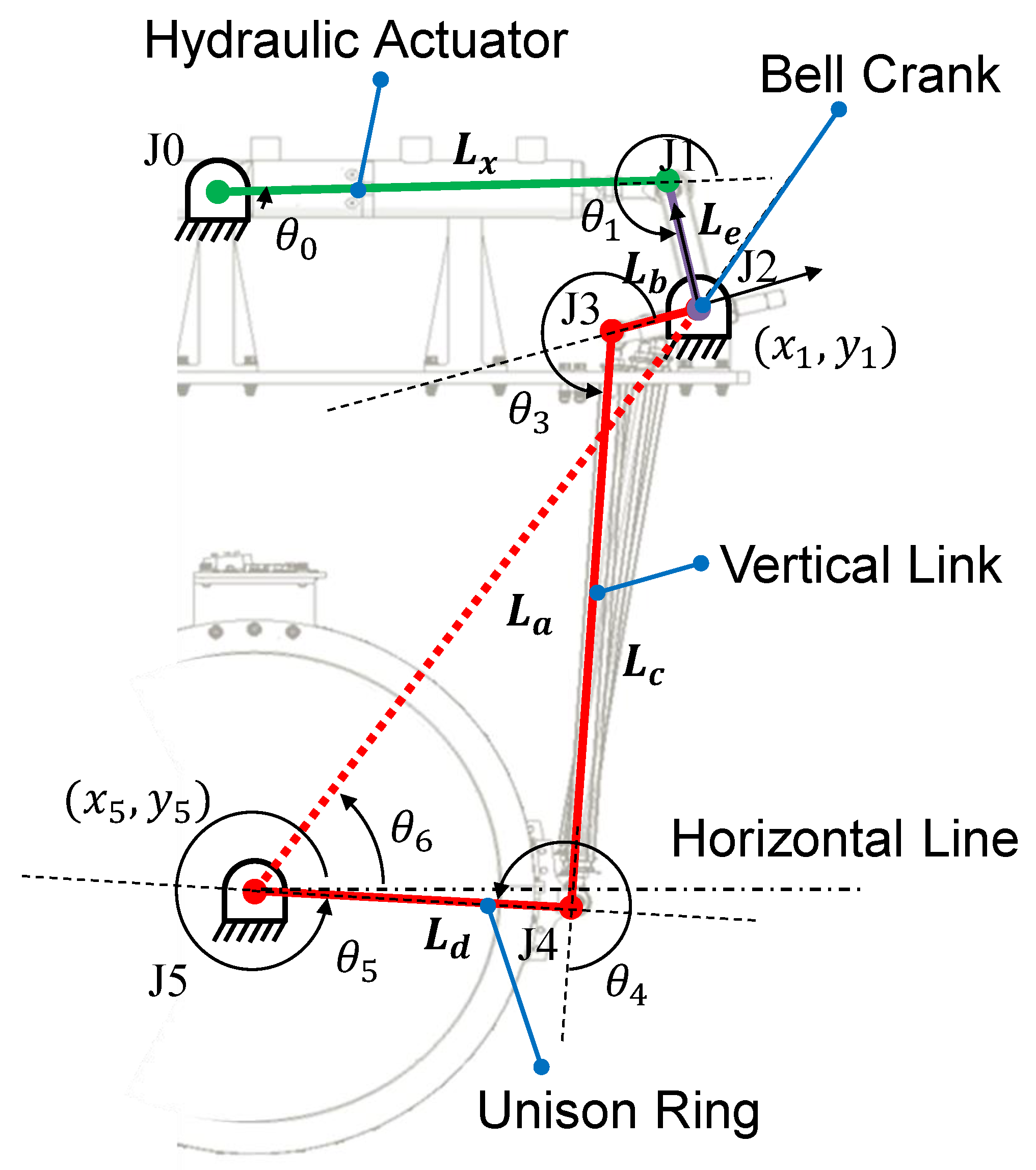
3. Analytical Model of the VGV Link Mechanism

3.1. Model for the Links from Actuator to Unison Ring

The entire VGV link mechanism is divided into two parts and these were analyzed separately by reason of modeling convenience.
First, link connections from the hydraulic actuator to the unison ring are shown in Figure 2. With the assumption that the unison ring rotates with respect to the center of the compressor plane, these link connections can be simplified as in-plane motion. With change in the length of the actuator stroke (represented as green line in Figure 2), the bell crank rotates on its pivot like a revolute joint having one degree of freedom, then it induces movement of the vertical link.
The upper connection (consisting of links L x and L e , and joints J0, J1, and J2, represented as green and purple lines in Figure 2) can be summarized as three revolute joints and three parts, including a fixed part (ground). This results in zero DOF from a two-dimensional Grubler’s equation (based on in-plane motion assumption).
D O F   =   3 ( N l i n k 1 ) 2 N J 1 N J 2
A lower connection (including links L a , L b , L c , and L d , and joints J2, J3, J4, and J5, represented as red lines in Figure 2) is a typical four-bar mechanism, and it has one DOF. However, the movement of the lower connection is coupled on the upper connection motion via the bell crank. The sole solution for positions of upper and lower connections thus can be obtained when the actuator stroke ( L x ) is defined.
The relation from the actuator stroke to the angle of the bell crank can be derived from the following simple transformation matrix.
T J 2 0   =   T J 0 0 T J 1 J 0 T J 2 J 1
where T P 2 P 1 represents a transformation matrix to change position with direction from P1 to P2. For example, T J 2 0 indicates a transformation matrix to define the position and direction of joint J2, with respect to the left-end mount of the actuator. The transformation matrix contains a 3 × 3 directional transformation matrix based on Euler angles and the position information in the last column. In this case, Equation (3) can be represented in the form of the following detail matrix.
[ r 11 r 12 r 21 r 22 r 13 x 1 r 23 y 1 r 31 r 32 0 0 r 33 0 0 1 ] = [ c θ 0 s θ 0 s θ 0 c θ 0 0 0 0 0 0 0 0 0 1 0 0 1 ] [ c θ 1 s θ 1 s θ 1 c θ 1 0 L x 0 0 0 0 0 0 1 0 0 1 ] [ 1 0 0 1 0 L e 0 0 0 0 0 0 1 0 0 1 ]
where and represent cosine and sine functions, respectively, and r x x represents xx-directional values of the links (1 for x-axis, 2 for y-axis, 3 for z-axis).
The unknown variables of Equation (4) are θ 0 and θ 1 . They can be obtained using the actuator stroke, the bell crank angle, and the given joint J2 positions with Equation (4). Nonlinear simultaneous equations of Equation (4) are not directly computed, so simplification by multiplying the inverse matrix of T J 0 0 to both sides of Equation (4) proceeds as shown in Equation (5).
[ c θ 0 s θ 0 s θ 0 c θ 0 0 0 0 0 0 0 0 0 1 0 0 1 ] [ r 11 r 12 r 21 r 22 r 13 x 1 r 23 y 1 r 31 r 32 0 0 r 33 0 0 1 ] =   [ c θ 1 s θ 1 0 L e c θ 1 + L x s θ 1 c θ 1 0 L e s θ 1 0 0 1 0 0 0 0 1 ]
The position terms of the Equation (5) matrix are summarized as Equations (6) and (7) to obtain θ 0 and θ 1 .
θ 1   =   cos 1 ( x 1 2 + y 1 2 L e 2 L x 2 2 L x L e )
θ 0   =   sin 1 ( y 1 L e cos θ 1 + L x y 1 x 1 L e sin θ 1 x 1 2 + y 1 2 )
Next, links from the lower part of the bell crank to connecting points of the unison ring are analyzed with an assumption of in-plane rotational motion with respect to the center of the engine. Thus, the connecting point of the unison ring and the vertical link is assumed to be a link that rotates at J5, a one DOF revolute joint (shown in Figure 2). Links L a , L b , L c , and L d show a general 4-bar link mechanism. The transformation matrix from bell crank to joint J5 is represented as in Equations (8) and (9).
T J 5 J 2   =   T J 3 J 2 T J 4 J 3 T J 5 J 4
[ r 11 r 12 r 21 r 22 r 13 x 5 r 23 y 5 r 31 r 32 0 0 r 33 0 0 1 ] = [ c θ 3 s θ 3 s θ 3 c θ 3 0 L b 0 0 0 0 0 0 1 0 0 1 ] [ c θ 4 s θ 4 s θ 4 c θ 4 0 L c 0 0 0 0 0 0 1 0 0 1 ] [ 1 0 0 1 0 L d 0 0 0 0 0 0 1 0 0 1 ]
Equation (10) is derived by multiplying the inverse matrix of T J 3 J 2 to both sides of Equation (9).
[ c θ 3 s θ 3 s θ 3 c θ 3 0 L b c θ 3 0 L b s θ 3 0 0 0 0 1 0 0 1 ] [ r 11 r 12 r 21 r 22 r 13 x 5 r 23 y 5 r 31 r 32 0 0 r 33 0 0 1 ] = [ c θ 4 s θ 4 0 L d c θ 4 + L c s θ 4 c θ 4 0 L d s θ 4 0 0 1 0 0 0 0 1 ]
x 5 and y 5 are positions of Joint 5 with respect to local coordinate of Joint 2 which is represented as black arrows in Figure 2. x 5 and y 5 are calculated with the following equations.
x 5   =   cos ( 3 2 π + θ 6 θ 0 θ 1 ) ( Δ x 2 + Δ y 2 )
y 5   =   sin ( 3 2 π + θ 6 θ 0 θ 1 ) ( Δ x 2 + Δ y 2 )
where ∆x and ∆y mean distance values of Joint 5 from Joint 2, according to the global coordinates.
The angle-variable θ 3 and θ 4 are obtained with respect to position x 5 and y 5 from Equation (10), and define the lower mechanism position.
θ 4   =   cos 1 ( ( x 5 + L b ) 2 + y 5 2 L d 2   L c 2 2 L d L c )
θ 3   =   sin 1 ( y 5 L d cos θ 4 + y 5 L c ( x 5 + L b ) L d sin θ 4 ( x 5 + L b ) 2 + y 5 2 )
By summarizing all the angles from Equations (6), (7), (13), and (14), the rotational angle of the unison ring is derived from Equation (15) based on their geometric relation.
θ 5   =   810 + ( θ 0 + θ 1 + θ 3 + θ 4 )

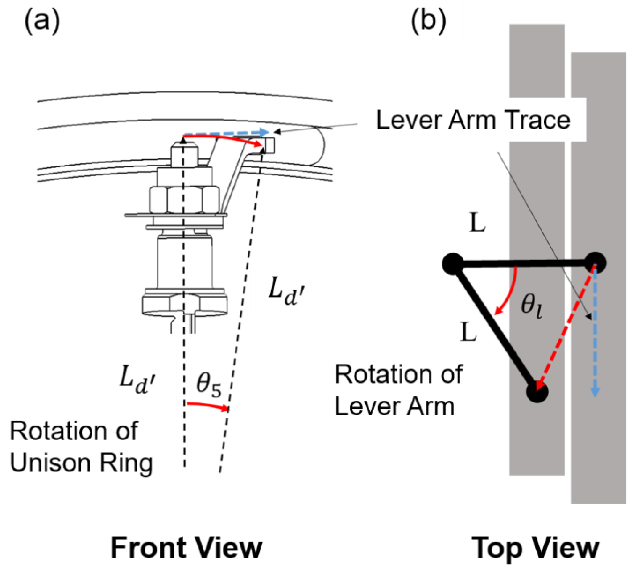
3.2. Model for the Links from the Unison Ring to the Vane

The rotational motion of the unison ring induces rotation of the lever arm and the vane connected to it. The lever arms make connection with the unison ring and the vanes as shown in Figure 3. The trace of the lever arm end viewed from the front side, follows the blue line in Figure 3, and its longitudinal distance is L d tan θ 5 , while the radial distance of the end of the lever arm is L d from the center of the engine. In the top view, the longitudinal distance of the lever arm end can be represented by the lever arm length and lever arm angle, as in Equation (16).
θ l   =   sin 1 ( L d tan θ 5 / L )
The mechanistic model comprising Equations (6), (7) and (13)–(16) has constants, state variables, input variables, and output variables, as shown in Table 2.
When the actuator stroke L x is defined first, the vane angle is calculated analytically using the mechanistic model just presented. The models can be used to adjust the links of VGV1 and VGV2 to obtain the vane angles demanded when a specific stroke L x is given.

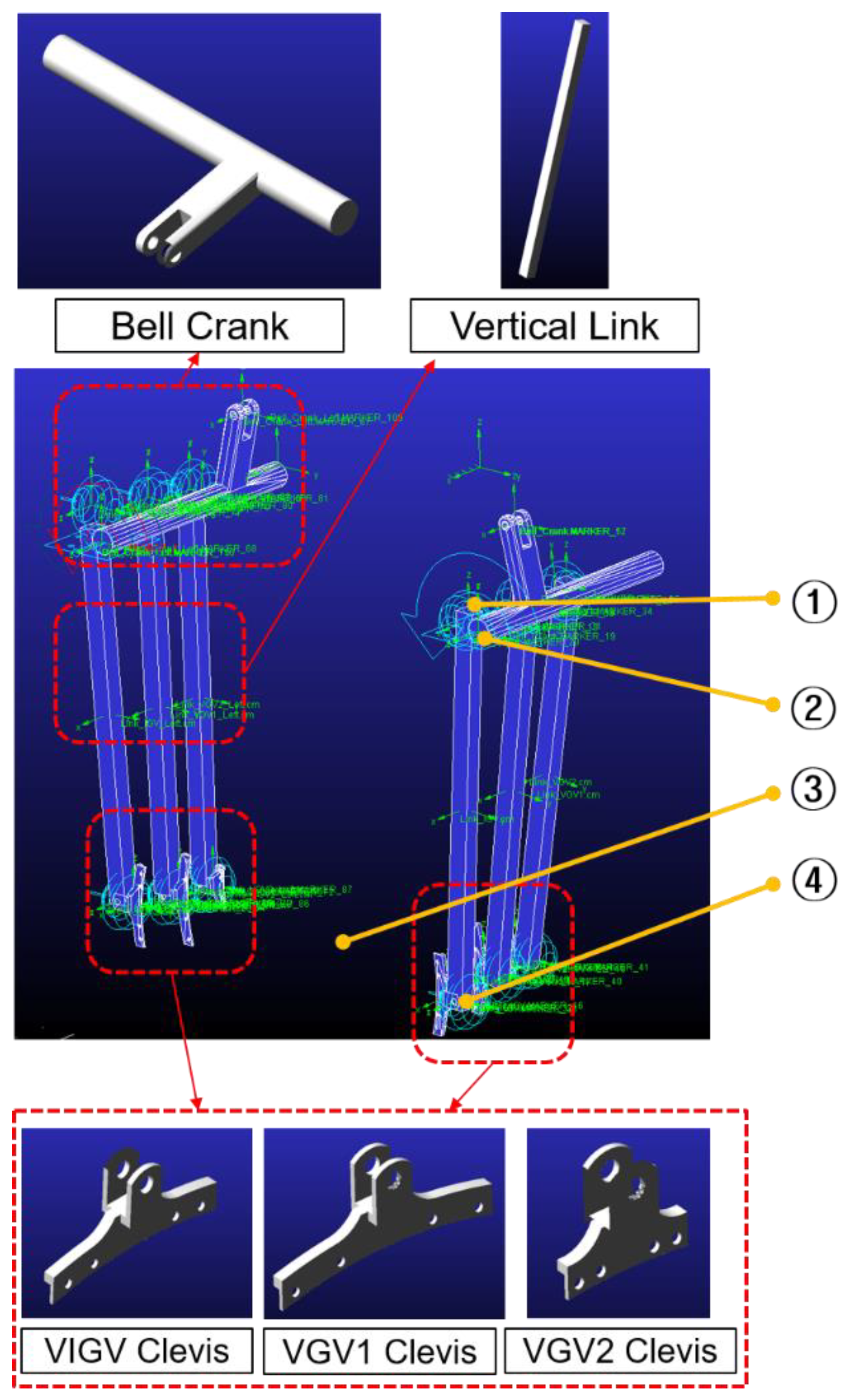
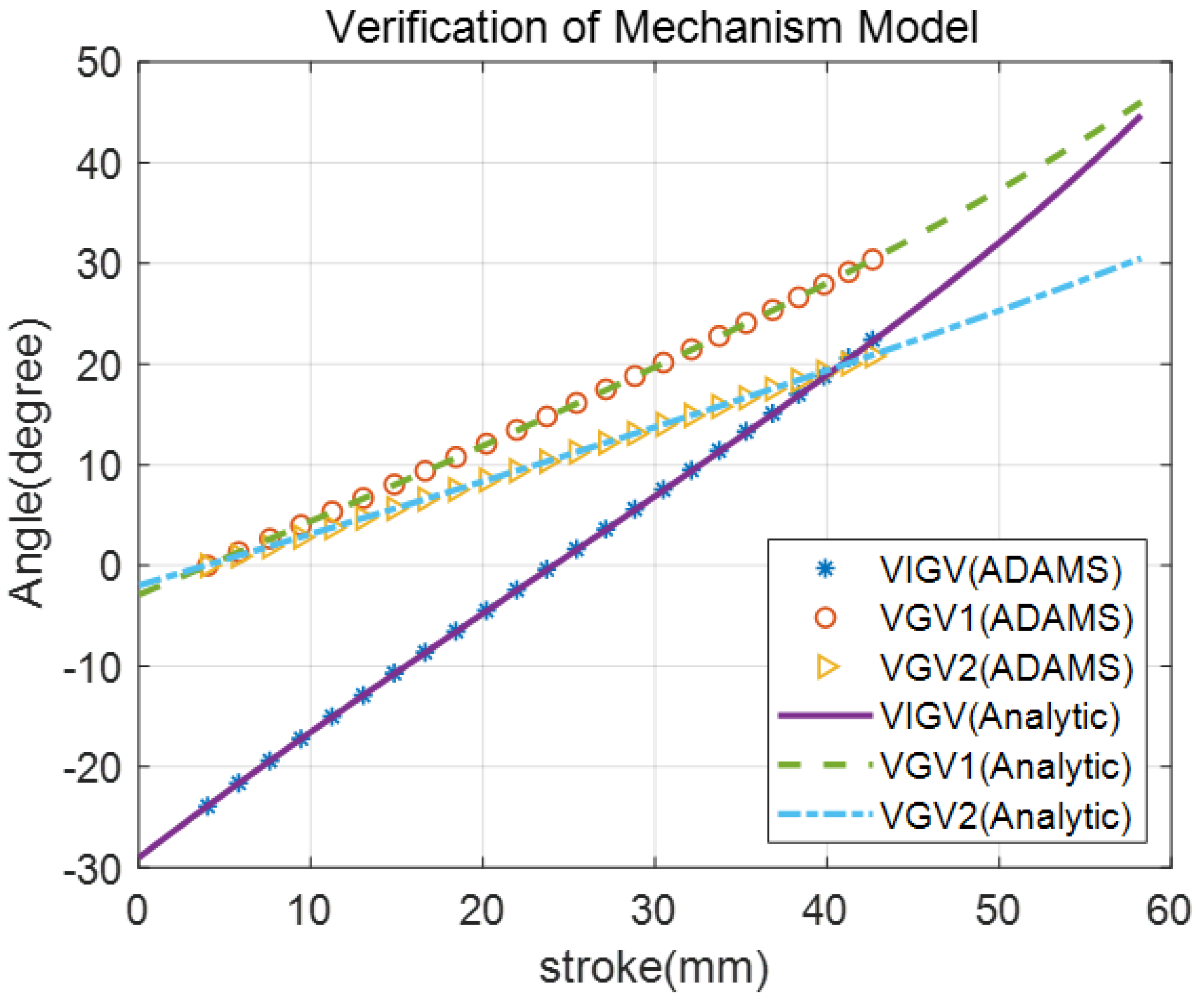
3.3. Model Validation by ADAMS Simulation

The derived model is validated by comparing the model in ADAMS (commercial mechanism analysis software, MSC software). In the case of the ADAMS model, the analysis is based on the three-dimensional space, so the axial movements of unison rings (also clevis) and longitudinal axis rotations of the vertical links, which are neglected in the analytical model are also included. The same actuator stroke ( L x ) was assigned to both models and verified by comparing the vane angles ( θ l ). The ADAMS model consists of the bell crank, vertical links, and clevis (connector of the vertical link to the unison ring), which moves with the unison ring (shown in Figure 4). A 3-D rendering of the actuators above the bell crank is omitted, and instead, the stroke input ( L x ) is numerically applied. The vane angle ( θ l ) is obtained from the rotational angle of the unison ring ( θ 5 ) using Equation (16) to reduce model complexity. Connections between the bell crank and vertical links are defined by the connections of geometric markers which represent the connection points of the bell crank and vertical links, without the 3-D rendering structure. Thus, invisible connections of markers can define relations of motions between the bell crank and vertical links. Different from the analytical model, the clevis (unison ring) has translational motion to the engine axis due to coupled motion with lever arms that rotate at their stem axis. Axial displacement of the clevis is applied using Equation (17) (refer to Figure 3).
x a   =   L ( 1 cos ( sin 1 ( L d tan θ 5 / L ) ) )
All the joints in the ADAMS model are listed in Table 3.
The VGV link mechanism has two identical link connections on the right and left side of the compressor, and it is manipulated by two hydraulic actuators. Thus, the inputs of the ADAMS model are two identical actuator strokes, and the outputs are stage vane angles calculated using the clevis rotational angle.
As presented in Figure 5, the results of the analytical mechanistic model coincide with those of the ADAMS model, even if the planar motion of the unison ring is assumed in the analytical mechanistic model. Axial movement of the vertical links due to the translational motion of the unison ring cannot affect the vane rotational angle because the vertical links are large enough to neglect the translational motion of the unison ring. In this research, the verified analytical mechanistic model is used instead of the ADAMS model to schedule the VGV link mechanism to reduce calculation time and to perform iterative calculations.

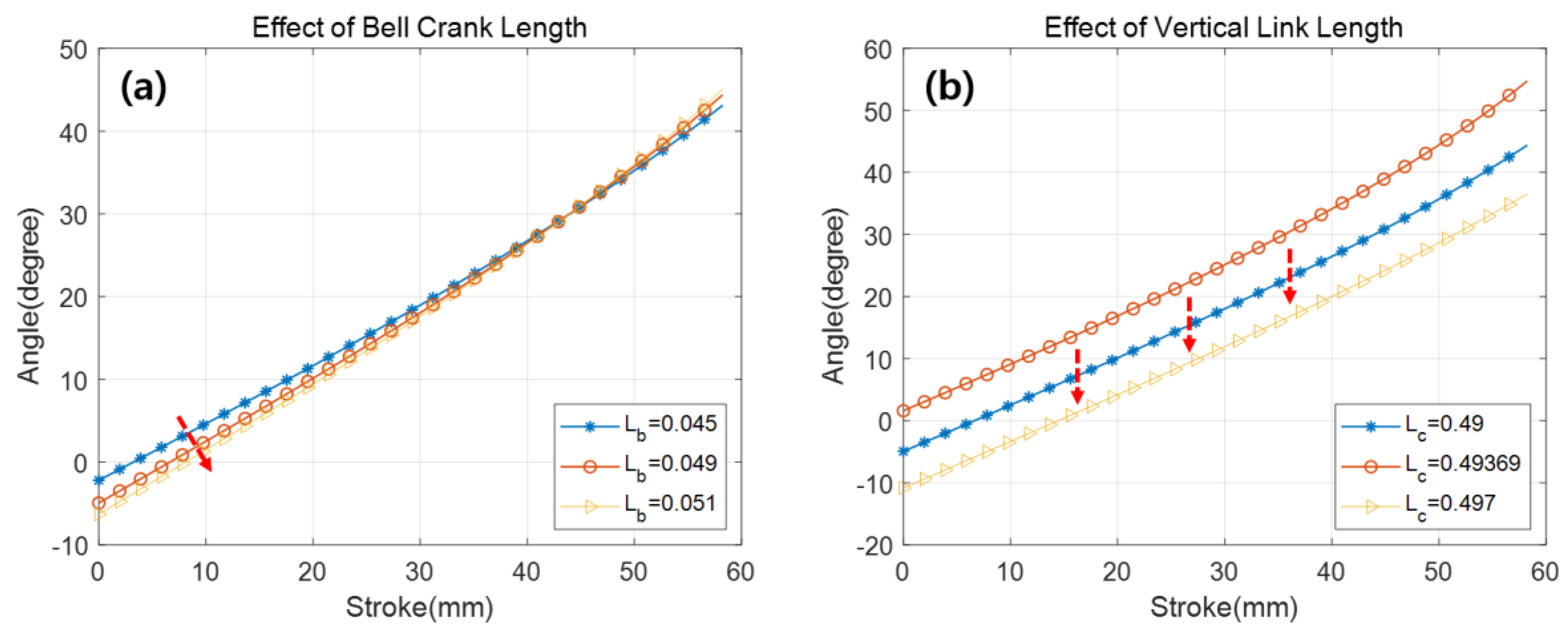
3.4. Parameters for Adjusting the Link Mechanism

The 3-stage VGVs in this research are mechanically coupled to one actuation system, thus, the stroke command for generating a VIGV angle does not satisfy the vane angle schedule of the remaining VGV stages (first-stage and second-stage VGVs in this case). Therefore, the link mechanisms of the first-stage and second-stage VGVs need to be modified to satisfy the VGV schedule by adjusting their link parameters, such as bell crank length ( L b ) and vertical link length ( L c ).
The bell crank length, an adjusting parameter, represents the distance between the rotation center of the bell crank and the mounting point of the vertical link. Adjusting the bell crank length changes the relations of the vane angle and actuator stroke, as shown in Figure 6a. Increasing the bell crank length makes the rotational radius of the pivot point of the bell crank and vertical link longer with respect to the rotational center of the bell crank. Then, larger vane angle changes can be obtained with identical bell crank rotational motion (increase in the slope of the curve in Figure 6a).
Changing the vertical link length changes the distance from the pivot point of the bell crank and vertical link to the pivot point of the unison ring and vertical link. Therefore, it changes the offset value of the curve representing the vane angle according to the actuator stroke (shown in Figure 6b).
The curve of the vane angle shown in Figure 6 can be fitted to a linear regression model that consists of curve slope value ( C s l o p e ) and offset value ( C o f f s e t ) as following equation.
θ l   =   C s l o p e × L x + C o f f s e t
An increase of 1mm in the bell crank causes 2% increase in the curve slope value, and an increase of 1mm in the vertical link causes 1.6 degree decrease in the offset value, respectively. Therefore, we can obtain a solution of link adjusting parameters to satisfy the coupled rest of VGV stages (in this study, VGV1 and VGV2) schedule requirements when stroke commands have been already presented.

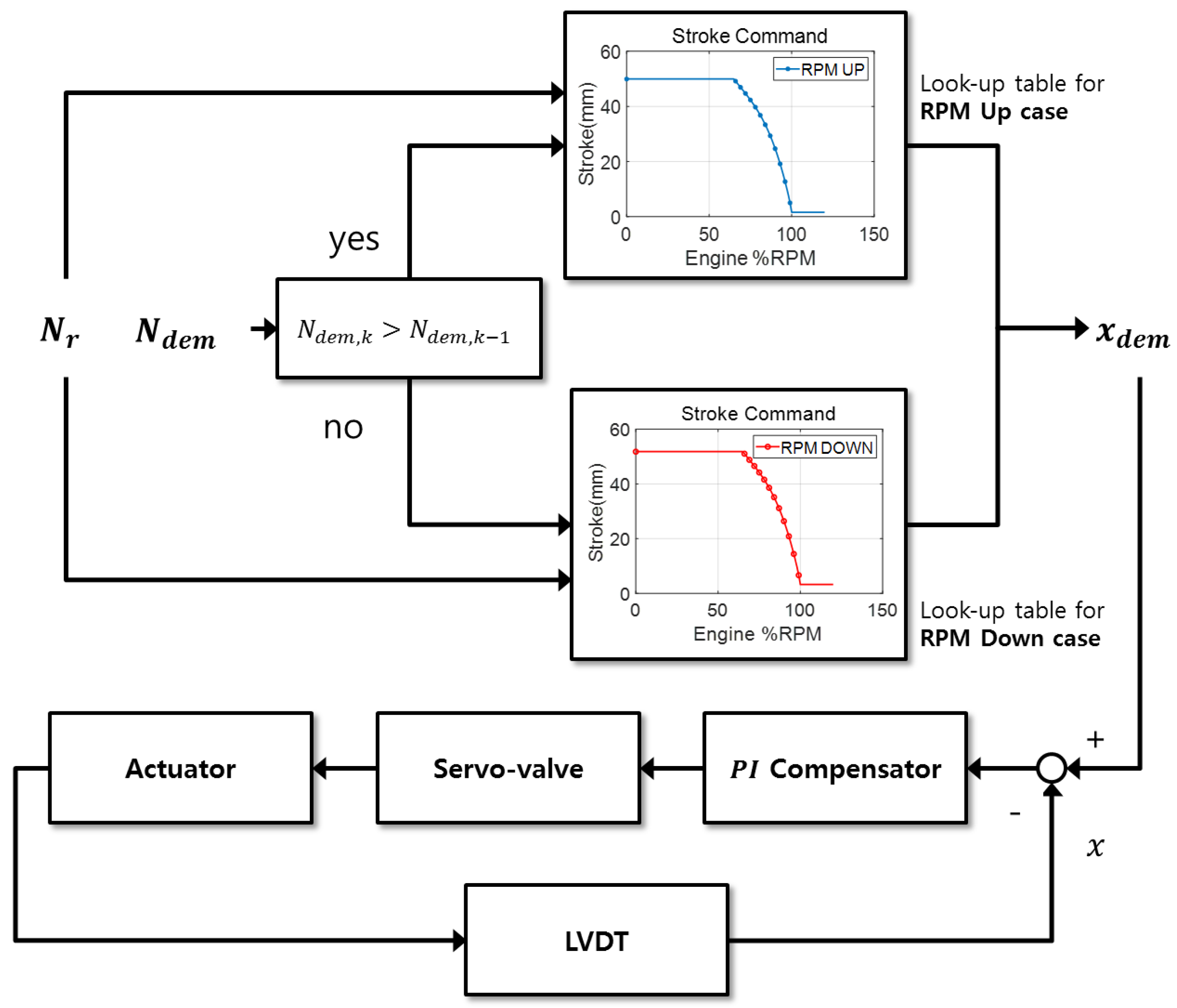
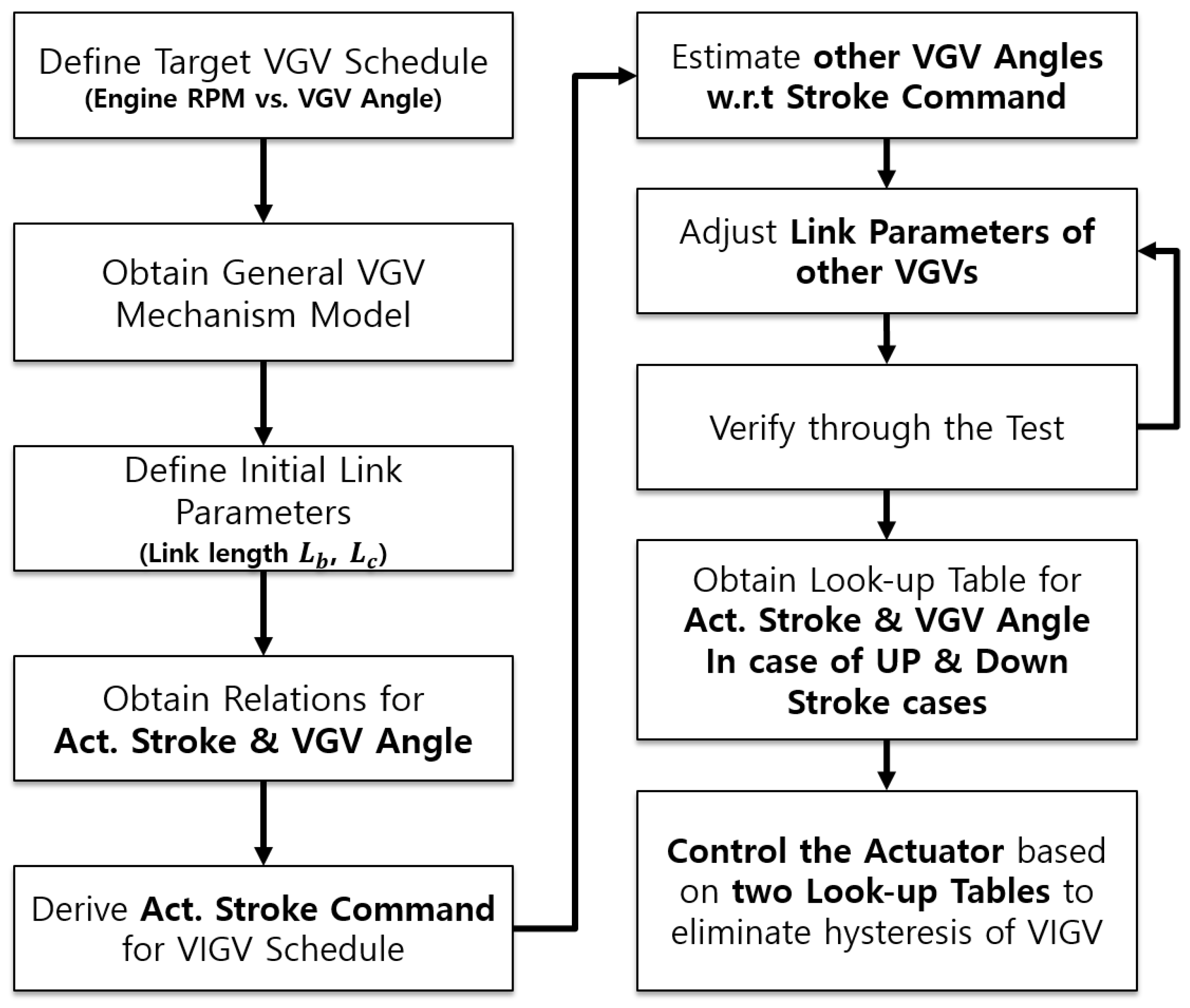
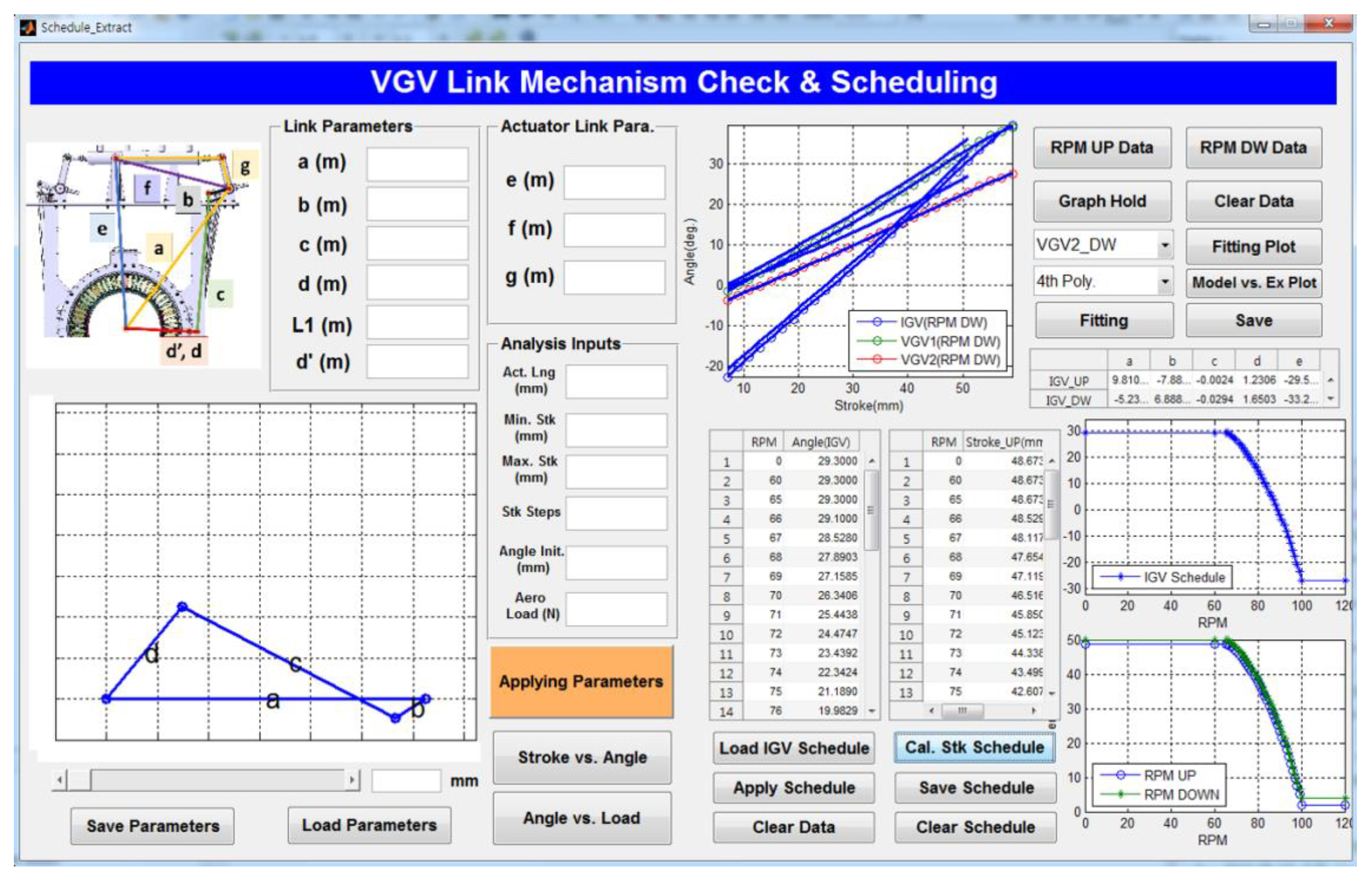
4. VGV Scheduling Method

Control commands from the engine controller are actuator stroke commands for scheduling the vane angle. The actuator controller accepts these control commands and calculates the error by sensing the actuator stroke from the LVDT (linear variable displacement transducer) module. Afterwards, it generates control signals to servo-valves of the hydraulic actuator to control the position of the actuator rod end, as shown in the lower part of Figure 7.
In this research, the stroke command of the controller was first established to satisfy the VIGV schedule, because the inlet mass flow rate of the compressor depends greatly on the VIGV angle. However, because all three VGV stages are mechanically coupled to the one actuation system, the angular difference of the vanes between schedules in VGV1 and VGV2 is inevitable, due to the stroke command only for the VIGV. The link adjusting parameters described in the previous section can be used to satisfy the schedules of all the VGV stages.
A real VGV mechanism has angle hysteresis according to the actuator stroke, due to DOF redundancy and eccentricity of the unison ring, thus, an ideal tabulated stroke command is not enough to realize the VGV schedule. In this research, the VIGV hysteresis was eliminated by applying two distinct schedule curves, the use of which depends on the moving direction of the actuator stroke. Compression or extension of the actuator stroke is equivalent to decrease or increase of the vane angle when the engine RPM is changing. Thus, the engine controller decides which look-up table is correct for the current state by figuring out the RPM trends.
If the measured engine RPM is used as the look-up table switching criterion, unnecessary frequent switching of the look-up table occurs due to noise signals in the engine RPM, and this also causes instability of the actuator system. For this reason, the look-up table is switched based on engine RPM demand under the assumption that the engine RPM tracking error is maintained within a stable range.
Although this hysteresis elimination method only applies to the VIGV stage, if each VGV stage constitutes an independent link mechanism, then all the hysteresis can be eliminated with a software application. Moreover, it can flexibly cope with the unexpected mechanical hysteresis such as the thermal growth of the parts, small deflection of the links, and wearing of the structures because the modification in each case can be done by adjustment of stroke commands in the control software without change of the mechanical parts. Figure 7 and Figure 8 summarize the control scheme and scheduling methodology developed in this research.
The stepwise method shown in Figure 8 was implemented using in-house software with a MATLAB GUI (graphical user interface), as shown in Figure 9. The derived mechanism model is calculated under the MATLAB environment, thus MATLAB GUI is the best platform to integrate the stepwise VGV scheduling method and to utilize efficient user interface. The user can obtain the solutions by entering few design parameters and only pressing push buttons. In this way, analysis of the link adjusting parameter and calculation of the stroke command to obtain the VIGV angle schedule can be performed simply by using this software.

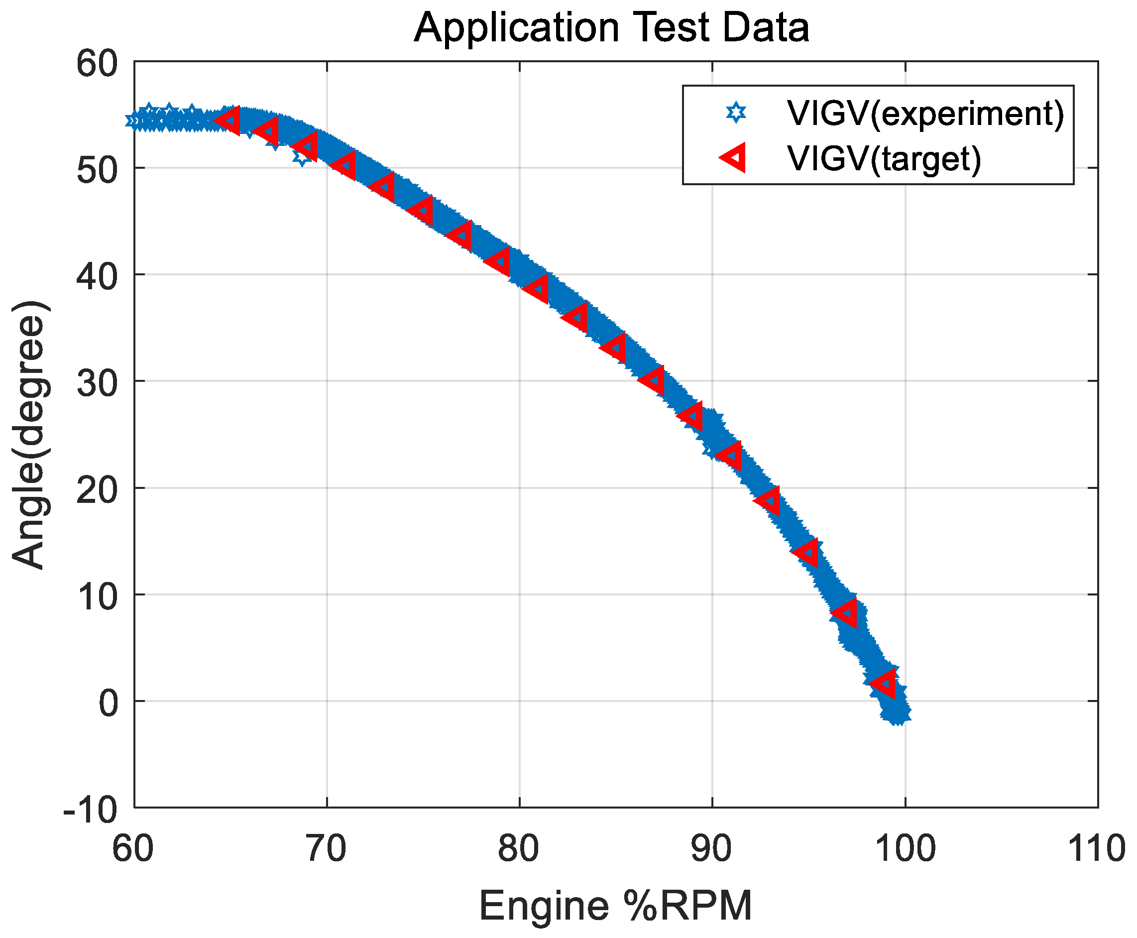
5. Engine Application Test

The proposed VGV scheduling method was applied to a real engine system. The initial link geometry is presented in Table 4, and the relation between the VGV angle and actuator stroke, which is derived from the analytical model in Section 3, is shown in Figure 10. Three-stage VGVs have different ranges of angles within the actuator stroke limit, and the VIGV has a wider range of angles.
The stroke command used to manipulate the target VGV angle can be obtained from the relations between the VGV angle and actuator stroke. The graph shown in Figure 11 is the target angle with respect to engine RPM that VGV vanes should fit. First, the stroke commands are obtained with respect to engine RPM to satisfy the target VIGV angles from the analytical mechanism model without considering RPM increasing or decreasing. However, the stroke commands make a discrepancy from the target value near 100% RPM in the cases of VGV1 and VGV2, as shown in Figure 12a (Error: 1.03 degree (VGV1), 2.16 degree (VGV2)). The bell crank length, one of the link adjusting parameters, can be adjusted to change the slope in Figure 12a. Changing the bell crank lengths from 48 to 49 mm for VGV1 and from 35 to 38 mm for VGV2 provides more accurate vane angles when the engine RPM is around 100%, as depicted in Figure 12b (Error: 0.39 degree (VGV1), 0.08 degree (VGV2)).
Through the real engine application test, we verified the effectiveness of the control method using dual schedule curves on the VIGV stage. The vane angles were measured using the potentiometers on the stem of the vanes, and VIGV angles with respect to the actuator stroke were obtained, as shown in Figure 13. This hysteresis data was divided into two stroke-angle relations to represent the extension and compression cases of the actuator stroke. Inherent mechanical hysteresis is about 1.6 degrees, as shown in Figure 13. These two stroke-angle curves were applied to the engine controller for the RPM up (increasing) and RPM down (decreasing) case, respectively.
The engine test results are presented in Figure 14. The data in Figure 14 includes all transient data during the entire engine run (over 30,000 samples) and includes multiple engine RPM rises and falls with 10 Hz sampling rate. The angular errors in the VIGV are summarized in Table 5. The mean error was 0.55 degree while inherent mechanical hysteresis was 1.6 degree, as describe in Figure 13. This represents overall hysteresis was reduced about 1.1 degree, in the VIGV stage. The resultant VIGV angles also trace the target angles well, and 0.47 mean angle error was measured especially in the range from 99% RPM to 100% RPM that is the engine design operating point. Considering that compressor instability during increase of the engine RPM, this tracking performance does not limit operation of the compressor.

6. Conclusions

The VGV link mechanism is usually composed of complex link connections, it is, thus, difficult to be modeled. In this study, the VGV link mechanism used for testing the compressor was simplified and represented in an analytical mechanistic model to estimate the rotational angles of the coupled multiple stages of the VGV. Coupled multiple stages of the VGVs (VGV1 and VGV2 stages in this case) were adjusted by changing link parameters (lengths of bell cranks and vertical links), and the relations between link parameters and VGV linkage motions were unveiled. As a result, angles of coupled stages of the VGVs at design operating point (100% RPM) could be adjusted with the small errors no more than 0.5 degrees from the target angles. Finally, the effectiveness of hysteresis reduction in the VIGV stage was verified through the real engine application test with applying the controller with the dual schedule curves.
The proposed scheduling methodology is based on the analytical mechanistic model and control logic software with dual schedule curves. Therefore, it can be directly applied to the compressor test-rig to adjust the VGV mechanism and to eliminate the hysteresis of links without using mechanical compensation, as well. Therefore, this method needs no extra cost to reduce hysteresis of the already developed VGV system.
In this study, the frictional interactions of joints and moving parts and flexibility of the links are neglected. Studies on various friction models with verified experimental data [17,18,19,20,21] and studies on hysteresis including structural flexibility or clearances of the joints have been continuously conducted [21,22,23,24,25]. Following to this state of art, the causes of link hysteresis will be dealt with and a sophisticated model including friction model of the joints will be developed in the future. Moreover, the novel non-hysteresis mechanism for VGVs will be studied as well.

Author Contributions

Conceptualization, S.J.K.; methodology, S.J.K.; investigation, T.K.; writing—original draft preparation, S.J.K.; writing—review and editing, T.K. All authors have read and agreed to the published version of the manuscript.

Funding

This research received no external funding.

Acknowledgments

This work has been supported by the projects “Concept design of low bypass ratio turbofan engine” and “Technology of Turbofan Engine System Integration Development” of Defense Acquisition Program Administration and Agency for Defense Development.

Conflicts of Interest

The authors declare no conflict of interest.

Nomenclatures

Acronym/NomenclatureDefinition
VGVVariable guide vanes
VIGVVariable inlet guide vane
IGVInlet guide vane
DOFDegree of Freedom
VGV1First-stage variable guide vane
VGV2Second-stage variable guide vane
J0, J1, J2, J3, J4, and J5Joint 0, 1, 2, 3, 4, and 5
ADAMSMulti-body dynamics analysis software
LVDTLinear Variable Displacement Transducer
RPMRotations per minute
MATLAB GUIMATLAB Graphical user interface
L a L b L c L d Length of link a, b, c, d
L x Length of link x (actuator stroke)
L e Length of link e (length of upper link of bell crank)
L Length of lever arm
L d Radial distance of the end of the lever arm from the center of the engine
N l i n k Total number of links in the mechanism
N J k Number of joints having k DOF
T P 2 P 1 Transformation matrix from P1 to P2
Cosine θ
Sine θ
r x x , r x x xx-directional values of the links(x: 1 for x-axis, 2 for y-axis, 3 for z-axis)
( x 1 ,   y 1 ) Position of Joint 2
( x 5 ,   y 5 ) Position of Joint 5w.r.t. local coordinate based on Joint 2
x, ∆yDistance of Joint 5 from Joint 2 according to x or y axis
θ k Angle value represented in Figure 2
θ l Lever arm rotational angle
x a Axial displacement of the clevis (unison ring)
C s l o p e Slope of the linear regression between vane angle and actuator stroke
C o f f s e t Offset of the linear regression between vane angle and actuator stroke
N r Engine rotor RPM
N d e m Engine rotor RPM demand
N d e m , k Engine rotor RPM demand at k-th step
x d e m Actuator stroke demand

References

  1. Rolls Royce. The Jet Engines, 4th ed.; Rolls Royce Limited: London, UK, 1986. [Google Scholar]
  2. Wirkowski, P. Modelling the Characteristics of Axial Compressor of Variable Flow Passage Geometry Working in the Gas Turbine Engine System. Pol. Marit. Res. 2007, 14, 27–32. [Google Scholar] [CrossRef]
  3. Salvage, J.W. Development of a Centrifugal Compressor with a Variable Geometry Split-Ring Pipe Diffuse. J. Turbomach. 1999, 121, 295–304. [Google Scholar] [CrossRef]
  4. Tibrewala, A.P.; Padave, T.J.; Wagh, T.P.; Gajare, C.M. Flow Aanlysis of Upstream Fluid Flow using Simulation for Different Positions of Optimized Inlet Guide Vane in Centrifugal Air Compressor. Am. J. Eng. Res. 2014, 3, 148–156. [Google Scholar]
  5. Mohseni, A.; Goldhahn, E.; Braembussche, R.A.V.D.; Seume, J.R. Novel IGV Designs for Centrifugal Compressors and Their Interaction with the Impeller. J. Turbomach. 2011, 134, 021006. [Google Scholar] [CrossRef]
  6. Ziegler, K.U.; Justen, F.; Rothstein, M.; Gallus, H.E.; Niehuis, R. Research on a Centrifugal Compressor of Variable Geometry. In Proceedings of the 15th International Compressor Engineering Conference, West Lafayette, IN, USA, 25–28 July 2000; pp. 89–96. [Google Scholar]
  7. Harrold, M.C. Stator Vane Actuator in Gas Turbine Engine. U.S. Patent 6769868 B2, 3 August 2004. [Google Scholar]
  8. Rusovici, R.; Feys, J.; Sepri, P.; Subramanian, C. Smart Actuation of Inlet Guide Vanes for Small Turbine Engine. ICAST 2014, 2014. [Google Scholar] [CrossRef]
  9. Robert, W. Duct with Vanes having Selectively Variable Pitch. U.S. Patent 3861822, 27 February 1974. [Google Scholar]
  10. Tsalavoutas, A.; Mathioudakis, K.; Stamatis, A.; Smith, M. Identifying Faults in the Variable Geometry System of a Gas Turbine Compressor. J. Turbomach. 2001, 123, 33–39. [Google Scholar] [CrossRef] [Green Version]
  11. Muir, D.E.; Saravanamuttoo, H.I.H.; Marshall, D.J. Health Monitoring of Variable Geometry Gas Turbine for the Canadian Navy. ASME J. Eng. Gas Turbines Power 1989, 111, 244–250. [Google Scholar] [CrossRef]
  12. Hashmi, M.; Lemma, T.A.; Karim, Z.A.A. Investigation of the Combined Effect of Variable Inlet Guide Vane Drift, Fouling, and Inlet Air Cooling on Gas Turbine Performance. Entropy 2019, 21, 1186. [Google Scholar] [CrossRef] [Green Version]
  13. Song, T.; Kim, T.; Kim, J.; Ro, S. Performance Prediction of Axial Flow Compression using Stage Characteristics and Simultaneous Calculation of Interstage Parameters. Proc. Inst. Mech. Eng. Part A J. Power Energy 2001, 215, 89–98. [Google Scholar] [CrossRef]
  14. Ishak, S.; Ahmad, A. Improving VIGV Predictive Monitoring by Developing a Failure Mode Virtual Snesor. In Proceedings of the 2017 7th IEEE ICCSCE, Penang, Malaysia, 24–26 November 2017; pp. 144–149. [Google Scholar]
  15. Hensges, M. Simulation and Optimization of an Adjustable Inlet Guide Vane for Industrial Turbo Compressors. In Proceedings of the ASME Turbo Expo 2008, GT2008-50242, Berlin, Germany, 9–13 June 2008. [Google Scholar]
  16. Uicker, J.J.; Pennock, G.R.; Shigley, J.E.; McCarthy, J.M. Theory of Machines and Mechanisms; Oxford University Press: New York, NY, USA, 2003. [Google Scholar]
  17. Al-Bender, F.; Lampaert, V.; Swevers, J. A Novel Generic Model at Asperity Level for Dry Friction Force Dynamics. Tribol. Lett. 2004, 16, 81–93. [Google Scholar] [CrossRef] [Green Version]
  18. Wojewoda, J.; Stefanski, A.; Wiercigroch, M.; Kapitaniak, T. Hysteretic Effects of dry friction: Modelling and Experimental Studies. Phil. Trans. R. Soc. A 2007, 366, 747–765. [Google Scholar] [CrossRef] [PubMed]
  19. Marques, F.; Flores, P.; Claro, J.C.P.; Lankarani, H.M. Modeling and Analysis of Friction including Rolling Effects in Multibody Dynamics: A review. Multibody Syst. Dyn. 2018, 45, 223–244. [Google Scholar] [CrossRef]
  20. Tan, H.; Hu, Y.; Li, L. Effect of Friction on the Dynamic Analysis of Slider-crank Mechanism with Clearance Joint. Int. J. Non-Linear Mech. 2019, 115, 20–40. [Google Scholar] [CrossRef]
  21. Xiang, W.; Yan, S.; Wu, J. Dynamic Analysis of Planar Mechanical Systems Considering Stick-slip and Stribeck Effect in Revolute Clearance Joints. Nonlinear Dyn. 2018, 95, 321–341. [Google Scholar] [CrossRef]
  22. Tian, Q.; Flores, P.; Lankarani, H.M. A Comprehensive Survey of the Analytical, Numerical and Experimental Methodologies for Dynamics of Multibody Mechanical Systems with Clearance or Imperfect Joints. Mech. Mach. Theory 2018, 122, 1–57. [Google Scholar] [CrossRef]
  23. Lai, X.; He, H.; Lai, Q.; Wang, C.; Yang, J.; Zhang, Y.; Fang, H.; Liao, S. Computational Prediction and Experimental Validation of Revolute Joint Clearance Wear in the Low-velocity Planar Mechanism. Mech. Syst. Signal Process. 2017, 85, 963–976. [Google Scholar] [CrossRef]
  24. Erkaya, S. Experimental Investigation of Flexible Connection and Clearance Joint Effects on the Vibration Response of Mechanisms. Mech. Mach. Theory 2018, 121, 515–529. [Google Scholar] [CrossRef]
  25. Ohe, T.; Lee, J.H.; Okamoto, S. Experimental Verification of Nonlinear Characteristics with Hysteresis in Variable Stiffness Robotic Joint. In Proceedings of the 16th International Conference on Ubiquitous Robots, Jeju, Korea, 24–27 June 2019. [Google Scholar]
Figure 1. Variable guide vane (VGV) link mechanism of the compressor.
Applsci 10 06643 g001
Figure 2. Simplified diagram of VGV links and joints
Applsci 10 06643 g002
Figure 3. Lever arm kinematics. (a) Front view; (b) Top view.
Applsci 10 06643 g003
Figure 4. Layout of the Adams Mechanistic Model.
Applsci 10 06643 g004
Figure 5. Verification results of the link mechanism model.
Applsci 10 06643 g005
Figure 6. Effect of link lengths on relations between vane angle and actuator stroke. (a) Effect of bell crank length ( L b ); (b) Effect of vertical link length ( L c ).
Applsci 10 06643 g006
Figure 7. VGV link mechanism control diagram.
Applsci 10 06643 g007
Figure 8. VGV scheduling methodology flow chart.
Applsci 10 06643 g008
Figure 9. In-House software for scheduling VGVs.
Applsci 10 06643 g009
Figure 10. Link mechanism results based on the initial geometry.
Applsci 10 06643 g010
Figure 11. VGV scheduling target.
Applsci 10 06643 g011
Figure 12. Scheduling results. (a) before link adjustment, (b) after link adjustment.
Applsci 10 06643 g012
Figure 13. Mechanical hysteresis of link mechanism.
Applsci 10 06643 g013
Figure 14. VIGV angle measurement results from engine test.
Applsci 10 06643 g014
Table 1. Joints and links of the VGV’s link mechanisms below the bell cranks.
DescriptionTypeNumbers
N J 3 Number of 3 DOF JointSpherical Joint
(2 x bell crank-vertical link)
(2 x clevis-vertical link)
4
N l i n k Number of PartsLinks
(2 vertical links,
1 unison ring, ground)
4
Table 2. Variables of the VGV mechanistic model.
Variables
Constants L a , L b , L c , L d ,   L e ,     L d ,   L ,   θ 6
State variables θ 0 ,   θ 1 ,   θ 3 ,   θ 4 ,   θ 5
Inputs L x
Outputs θ l
Table 3. Definitions of joints in ADAMS model.
Number in Figure 4JointPartsDOFs
SphericalBell Crank, Vertical Link3
RevoluteBell Crank, Ground1
Slide + RevoluteClevis, Ground2
SphericalVertical Link, Clevis3
Table 4. Geometry parameters of the initial link mechanism (unit: mm).
ParametersVIGVVGV1VGV2
L e 112.3112.3112.3
L b 74.048.035.0
L c 497.1493.7498.8
Table 5. VIGV angular errors obtained from the engine application test (unit: degree).
Max. ErrorOverall Mean ErrorMean Error
(99% RPM < RPM < 100% RPM)
2.170.550.47

