Abstract
As a hard and brittle material, KDP crystal is easily damaged by the irradiation of laser in a laser-driven inertial confinement fusion device due to various factors, which will also affect the quality of subsequent incident laser. Thus, the mechanism of laser-induced damage is essentially helpful for increasing the laser-induced damage threshold and the value of optical crystal elements. The intrinsic damage mechanism of crystal materials under laser irradiation of different pulse duration is reviewed in detail. The process from the initiation to finalization of laser-induced damage has been divided into three stages (i.e., energy deposition, damage initiation, and damage forming) to ensure the understanding of laser-induced damage mechanism. It is clear that defects have a great impact on damage under short-pulse laser irradiation. The burst damage accounts for the majority of whole damage morphology, while the melting pit are more likely to appear under high-fluence laser. The three stages of damage are complementary and the multi-physics coupling technology needs to be fully applied to ensure the intuitive prediction of damage thresholds for various initial forms of KDP crystals. The improved laser-induced damage threshold prediction can provide support for improving the resistance of materials to various types of laser-induced damage.
1. Introduction
Inertial confinement fusion (ICF) has gradually become one of the most promising clean energy sources that people are striving for [,]. Lawrence Livermore National Laboratory (LLNL) built the largest large-scale laser fusion device: National Ignition Facility (NIF) [,]. The Limeil Laboratory of France and the China Academy of Engineering Physics (CAEP) [] also built laser fusion ignition devices successively. Nature published two consecutive articles in 2014 [] and 2019 [] to report new advances in inertial confined fusion. In the driven laser system engineering for ICF devices, large quantity, caliber, and special performance of optical components are required []. To achieve favorable absorption of the laser by the target fuel, the ultraviolet (UV) light with shorter wavelength is preferred. The most effective way to obtain high power UV light is to convert the laser from fundamental frequency to multi-frequency and triple-frequency light through large diameter KH2PO4 (KDP) crystals. As a result, the laser damage resistance of the optical crystal materials in the devices determines the transmission quality of the whole optical path, seriously restricting the quality of the output laser, which is an urgent technical problem in the engineering application [,].
KDP crystals are used as electro-optical switches and frequency conversion elements at all levels of bridging optical paths in laser-driven fusion engineering due to the wide spectral transparency and high nonlinear conversion efficiency []. Laser-induced damage (LID) [] will occur inside or on the surface of materials when the KDP crystals are exposed to the sufficiently high laser intensity that exceeds the extreme value that the materials can withstand. Yoreo et al. [] summarized two kinds of crystal damage depending on the location of damage: bulk damage and surface damage. The bulk damage is relatively evenly distributed inside the crystal. The porosity and the deposited impurities during the growth of crystal will absorb the sufficient laser energy and explode to form the central melted and fractured zone several to tens of micrometers in diameter [,,]. In contrast, the surface damage is usually initiated by the near surface impurities, the defects, such as particles or scratches, remaining during the processing and surface contamination [,]. In response to these varied damages with different laser intensity, the laser induced damage threshold (LIDT) is introduced to show the initiation of laser induced damage [,].
At present, a series of studies on the damage mechanism and the damage threshold of fused silica and other optical elements in ICF devices under laser irradiation have been carried out. The bulk damage of KDP crystal materials has been mostly studied by Ogorodnikov et al. [,]. However, the impurity particles inside the crystal have been avoided gradually due to the improvement of the growth technology of KDP crystal materials. The intrinsic damage mechanism of the surface damage of crystal materials should be considered significantly with the advent of ultra-short and short pulse regime. In addition, the actual laser induced damage threshold (LIDT) of the KDP crystal used in the current project is about 12–15 J/cm2 (1 ns) under the laser irradiation, which is still much smaller than the theoretical value of 147–200 J/cm2 (1–3 ns). The reason is that the mechanism of laser-induced surface damage of materials has not been fully interpreted [].
Because of the transparent properties of the KDP crystal material, part of the energy of the incident laser is reflected or scattered, the other part of the energy is absorbed by the material, and the rest continues to propagate forward through transmission. At this time, the nonlinear absorption of the laser will cause physical phenomena such as temperature rise, melting, vaporization, thermal compression shock, plasma expansion, and wave shock, which are extremely complex process []. It is of great significance to understand the mechanism of laser induced damage for improving the laser induced damage threshold of optical crystal materials. To determine the degree of damage in KDP crystal materials caused by the laser irradiation, LIDT is usually the criterion that is used to improve the anti-laser damage ability of materials. Keldysh and Sparks et al. [,] proposed the ionization rate model. Jing et al. [] integrated the whole ionization process and used the evolution process of free electron density to characterize the trend of laser-induced damage under the influence of incident laser intensity indirectly. The light intensity modulation phenomenon of the incident laser inside the material was introduced to characterize the change of damage threshold by Feit []. In addition, the finite-difference time-domain (FDTD) algorithm was also applied to KDP crystals to determine the light intensity enhancement factor (LIEF) inside the material to show the trend of damage [,]. However, both the exploration of free electrons and LIEF in an electric field can only give the single trend of damage. The damage trend reflected by LIDT cannot be intuitively characterized. A simulation technique that can intuitively characterize the damage threshold needs to be further explored.
To understand the principles of laser-induced damage of KDP crystals deeply, the surface damage caused by the irradiation of laser on KDP crystal materials will be reviewed in detail from three stages of energy deposition, damage initiation, and damage forming. The energy deposition regime of KDP crystals in the early stage of laser irradiation was analyzed, which will be helpful to establish the evaluation criteria of the anti-laser damage ability of KDP crystal elements, so as to delay the service life of the project. In addition, combined with different forms of defects, the experiments and theoretical simulation of laser induced damage mechanism were sorted and reviewed. The initial energy deposition and the damage caused in the middle and late stages were discussed to optimize the processing parameters of KDP crystal materials. The damage threshold prediction method has also been sought.
2. Mechanism of Pulsed Laser-Induced Surface Damage
With the continuous upgrading of high-power laser systems, the interaction mechanism between laser and crystal materials is of interest. The interaction between laser and crystal materials is closely related to laser parameters such as pulse width, wavelength, and spot area.
Figure 1 [,] shows the physical phenomenon on optical materials induced by lasers with different power densities. As a transparent optical material, KDP crystal has a relatively low absorption coefficient. When the laser is irradiated on the ideal KDP crystal, most of the energy of the laser will be transmitted, and only a small part of the laser energy will be absorbed.
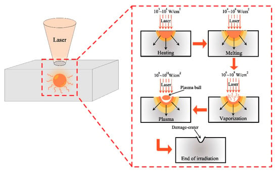
Figure 1.
The physical phenomenon of the interaction of laser and optical crystal materials at different light intensity levels.
It is necessary to consider how to determine the occurrence of damage exactly, i.e., the determination of the damage initiated for understanding the LIDT of KDP crystal. It is generally believed that the LID is initiated when any permanent change occurs on the surface of the material. At present, the critical free electron density is used as the criterion of damage judgment to determine the LIDT. The critical free electron density ncr of the material can be expressed as Equation (1) []:
where e is the electronic charge, ε0 represents the dielectric constant of electron space, me is the electron reduced mass, and ω is the angular frequency of incident laser.
2.1. Near Surface Impurity Thermal Absorption Damage
Unlike the manifestations of bulk damage, near-surface impurities will cause surface damage. KDP crystals are easily doped with various metal cation impurities in the near surface during the growth process. Miki et al. [] studied the KDP crystals and found that the impurity particles contained in the near surface of crystal would scatter or converge the incident laser, resulting in the enhancement of the local light field of the element. In addition, the researchers [,,] have found that the incident energy of the laser was strongly absorbed by the impurity ions. Generally, the laser energy absorbed by impurities is several orders of magnitude higher than the intrinsic absorption of crystal materials. Therefore, the strong absorption of the laser by impurities in the crystals will cause the rise of local temperature, which will further lead to the melting and cracking of the material surface.
Koldunov and Manenkov et al. [,,] assumed that the impurities inside the optical materials were in the shape of small balls with the radius of r. Based on this assumption, the thermal explosion (TE) model was constructed to explain the absorption of radiation by impurities in the materials. The heat conduction equation can be described to show the radiation absorption of impurities [,].
where ρ, c, and k are the density, thermal capacity and thermal conductivity of impurities and host materials, respectively. T is the temperature of impurities, Q is the power density of the thermal sources, and I is the laser intensity and g(t) is the temporal shape of the laser pulse. It is clear that Q(T, Ig(t)) is associated with absorption of radiation by impurities.
Chen et al. [] explored the influence of the near surface impurities in the KDP crystal on its surrounding temperature and stress, as shown in Figure 2, which well explained the strong absorption of energy of impurities.
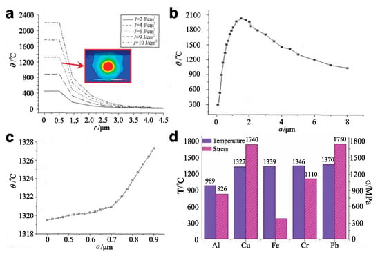
Figure 2.
Effect of near surface impurities in KDP crystal on temperature and stress of materials. (a) Distribution of temperature field around impurities under laser irradiation with different energy densities. The enlarged view shows the three-dimensional temperature field at I = 6 J/cm2, a = 0.5 μm; (b)Temperature variation curve of impurity with its dimension; (c) Temperature variation curve from the center to the edge of Fe impurity; (d) The contract curve of maximum temperature and thermal stress of different types of impurities [].
It can be seen that the temperature near the impurity is directly related to the energy density of the incident laser. The greater the incident laser energy density, the more energy the impurity absorbs, resulting in a sharper temperature rise of impurity. The temperature rise of impurities is approximately proportional to the energy density of the incident laser.
In addition, the properties of impurities also result in energy absorption. Chen and Mu et al. [] indicated that the size and density of impurities have an effect on the energy absorption of impurities. Chen et al. proposed that there was a critical impurity size that made the impurities absorb the most energy and had the highest temperature. Once the impurity radius a is less than or greater than this critical value, the energy absorbed by the impurities after laser irradiation will be very small, and the temperature near the impurity will be very low, which is not easy to cause damage. The type of impurity inside the KDP crystal also absorbs energy differently. The absorption of energy by different types of impurities will lead to the differences in temperature rise and thermal stress, as shown in Figure 2d.
Bercegol and Carr et al. [,] established the models containing near surface impurities, and the damage process of submicron-level impurities in optical materials induced by laser was simulated by hydrodynamic (HD) simulations, as shown in Figure 3. In contrast to the bulk surface, the impurities near the surface will form craters on the surface and cause considerable damage.
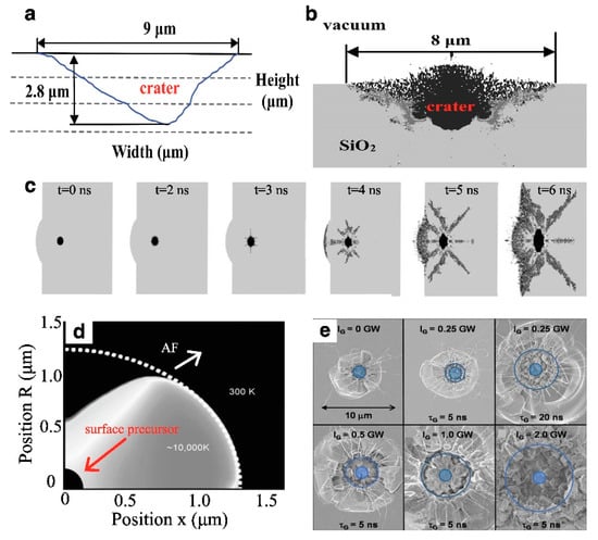
Figure 3.
Contrast between the hydrodynamic simulation of laser-induced damage of optical materials containing impurities and the experimental of laser-induced damage. (a) Cross-sectional view of AFM (Atomic Force Microscope) measurement of damage pit by laser irradiation; (b) HESIONE simulation of damage pit by laser irradiation; (c) Illustration of the fracture wave generated by the irradiation of impurities at different times following the arrival of the laser pulse; (d) HD simulation of the formation of impurity absorption front (AF) while the laser was on and the temperature profile; (e) SEM image of the damage sites produced by absorption front initiator pulses followed by various growth feet [,].
The simulation results are consistent with the experimental data, which reflects the mechanism of impurity thermal absorption damage well. Koldunov et al. [] analyzed the thermal conduction model and constructed a nonlinear heating model of impurities. It was found that the relationship between the LIDT and the pulse width under different laser pulse shapes (rectangular and gaussian) can be expressed by the following formula, especially in the case of longer pulse laser irradiation.
where the τp is pulse width and τ is heat relaxation time in the medium. It is worth noting that there is τp ≥ τ. Ith is the threshold intensity. On the basis of the analysis of above models, it is determined that the thermal explosion model caused by impurities is reasonable only when the laser irradiation time is long enough.
2.2. Ionization Damage
2.2.1. Photoionization
With the improvement of the processing technology of KDP crystal materials, the impurities in KDP crystal materials can be avoided gradually. The study of intrinsic damage gradually became clearer. As a transparent crystal material, KDP crystals without any impurities have relatively low absorption of incident laser energy. Therefore, the impurity-based TE model is no longer applicable [].
For the laser-induced damage without impurities, Carr et al. [,,] proposed that the laser damage of transparent optical crystal materials was caused by the change of energy level in multiphoton absorption, and a locally dense plasma area will be formed in the process of damage. In addition, the birth of high-power density ultrashort pulse laser made rapid ignition become the key for laser driven fusion engineering. The appearance of ultra-short pulse laser was helpful to understand the interaction between laser and transparent optical materials. The intrinsic damage of KDP crystal materials under laser irradiation has gradually become the key point of research.
Photoionization refers to the process in which the electrons in the equilibrium state inside the material absorb photons directly and are excited to the excitation state when the laser interacts with optical crystal materials []. Actually, the excitation condition for electrons is to ensure that the energy of the incident photon is equal to the band gap between the excited state and the ground state. In general, the electron absorbs only one photon from ground state to excited state. However, if the energy of a single photon is less than this bandgap, the electron cannot be excited []. Keldysh et al. [] noted the laser intensity and frequency, and proposed a comprehensive theory of photoionization.
It is possible that an electron will absorb two or more photons and transition if the width of this band gap is equivalent to the total energy of two or more photons under the intense electric field. This kind of mechanism is called multiphoton ionization regime. Nowadays, the laser electric field has been able to reach a certain level, far exceeding the perturbation limit of crystal materials [,]. This situation means that the external reinforcement field will break the Coulomb well of the bound electrons and excite the free electrons through short tunnel ionization. As a result, there are two different regimes of photoionization, the multiphoton ionization (MPI) and the tunneling ionization (TI). Keldysh used the following formula to describe the photoionization rate based on the understanding of photoionization.
where ћ is the reduced Planck constant. me represents effective electronic mass. ω is the angular frequency of the incident laser. K(γ), E(γ) represent the first and second complete elliptic integral, respectively. γ is the adiabatic parameter of the solid material, also known as the Keldysh parameter, which can be shown as
where ν is the laser frequency, me, e, and n are the reduced mass, electronic charge, and the index of refraction of materials, respectively. Eg is the band gap, which is 7.7 eV. Figure 4 [,,] shows the photoionization rate as a function of laser intensity for 800 nm laser in KDP.
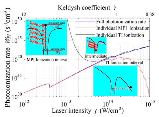
Figure 4.
Correlations between incident laser intensity I and PI rate WPI with the consideration of full Keldysh’s ionization, individual multiphoton ionization (MPI) and tunneling ionization (TI) ionizations under 800 nm lasers irradiation [].
The effect of multiphoton ionization and tunneling ionization on photoionization can be accurately characterized by the Keldysh coefficient γ, as shown in Figure 4.
The process of photoionization is quite different under the strong field and the weak field. It can be seen that the photoionization is a mix between tunneling and multiphoton ionization when the Keldysh coefficient is around 1.5. With the increase of laser intensity, the multiphoton ionization coefficient will increase rapidly. In general, there is a linear relationship between the photoionization rate and the laser intensity, which is W ∝ I.
2.2.2. Avalanche Ionization
Actually, the laser will interact with the lattice, electron, and phonon in the crystal material when the incident laser irradiates the crystal material. As a result, the crystal material will absorb the incident laser. There are two types of electrons in the materials: bound electrons and free electrons. Generally, the ionization potential of the bound electron is much larger than the photon energy of the incident laser, so the bound electron cannot generally absorb photons. However, the normal impurity-free KDP crystals are dielectric materials that do not have free electrons in the body. Therefore, the source of free electrons is very important during laser irradiation. It is clear that the KDP crystal materials will not absorb the laser energy greatly.
Based on the understanding of the mechanism of photoionization, it can be found that the free electrons generated by photoionization in the early stage will be used as seed electrons to absorb photon energy by inverse bremsstrahlung under the subsequent laser irradiation. When the absorbed energy reaches a certain standard, the seed electrons will collide with the bound electrons in the valence band (VB) inside the material, causing it transition to the conduction band (CB) []. These new free electrons with lower energy will be generated, which will continue to absorb energy and collide with the atoms. With the increase of the density of free electrons in KDP crystal materials, the crystal materials with dielectric properties will gradually become the metal-like materials. Furthermore, with the subsequent irradiation of laser, the energy is continuously absorbed, and the density of free electrons inside the materials will increase rapidly. Researchers have successively constructed and optimized the corresponding models for avalanche ionization to determine the density of free electrons generated by avalanche ionization.
Sparks [,,] criticized the classical avalanche model with the imperfection of calculating the avalanche ionization rate and built the Sparks model for the avalanche ionization.
where τK represents the electro-acoustic relaxation time in the case of large angle scattering, τK = 1.36 × 10⁻¹⁵ s. τL is the electro-acoustic relaxation time when scattering at large and small angles, and τL= 8.77 × 10⁻¹⁶ s. E is the radiation electric field amplitude. ωp is the average phonon frequency, there is ћωp = 0.025 eV. The model assumes that the collision frequency and collision energy loss are constant during collisions between electrons. Sparks indicated that only when the average electron energy is greater than the energy required for electron impact ionization, can electrons reach the ionization limit, triggering avalanche ionization.
Drude et al. constructed the avalanche ionization model based on the heating phenomenon of free electrons in the conduction band [].
where σ represents the absorption cross section of the photon, and τc is the time of the electron collision.
Thornber et al. [] proposed an avalanche ionization model based on the semi-empirical formula, which can be applied to all electrical intensities.
where e is the electronic charge. vs ≈ 2 × 107 cm/s, which represents the saturation drift velocity. EI, EP, and EKT are, respectively, the electric fields that required to overcome ionization scattering, photon scattering, and thermal scattering. Thornber assumed that there is if the laser intensity satisfies this condition: . However, the theoretical and experimental values of the predicted laser induced damage threshold by this model are quite different []. Stuart et al. [] believed that the avalanche ionization rate is linearly related to the laser intensity.
Stuart et al. [] constructed the reasonable models for the avalanche ionization process of the specific materials under laser irradiation. For the heating problem of electrons in the conduction band, the dependence of electron energy on conductivity is considered in this model based on the Drude model.
where α is the avalanche ionization coefficient. This model proved that there is no connection between the laser-induced damage threshold and pulse width under short pulses. The decrease of LIDT is mainly affected by ionization [].
Cheng [] summarized these avalanche ionization models and the relationship between avalanche ionization rate and electric intensity is shown in Figure 5.
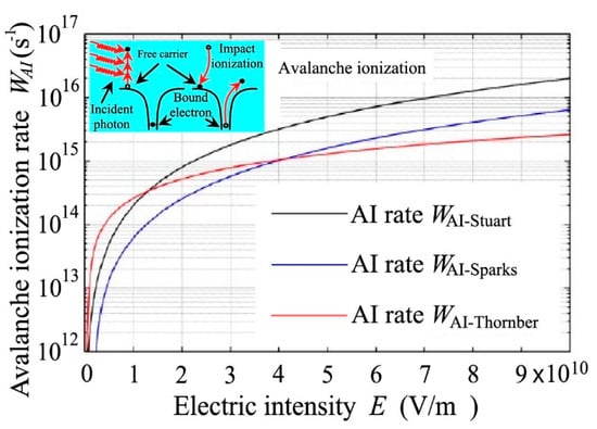
Figure 5.
Dependence of avalanche ionization rate WAI on electric intensity E calculated by AI models of Stuart, Sparks, and Thornber of KDP [].
The free electron density n in the valence band under avalanche ionization alters with time can be shown in Equation (12):
3. Exploration of the Initial Energy Deposition
The initial deposition stages of energy in the material determines the damage that the KDP crystal can withstand, while the final release stage of energy determines the morphology of damaged sites. The initial energy deposition of KDP crystal material is different under the laser irradiation with different pulse widths, which will lead to the diversification of the damage morphology in later stage. It is of great significance to study the main factors that reduce the damage threshold of KDP crystal surface for preventing the occurrence of damage. Therefore, it is very important to study the initial energy deposition inside the material under laser irradiation.
Since the high-power short-pulse lasers are used in the ignition devices of ICF mostly, the energy deposition and damage morphology under high-power short-pulse laser were summarized particularly.
3.1. The Formation and Evolution of Plasma
3.1.1. Irradiation of Ultra-Short Pulse Laser
Stuart et al. [] found that when the pulse period is greater than 100 ps, the damage of the dielectric material is mainly caused by the traditional heat transfer, while the damage of the material originates from the formation of laser-induced plasma when the pulse period is very short (<10 ps). As a result, the formation of plasma formation plays an important role in the initial energy deposition under the irradiation of short (picosecond to a couple of nanoseconds timescale) and ultra-short pulses (femtosecond timescale) [,,].
Based on the understanding of ionization, it can be found that the photoionization will be induced inside the material when high power ultra-short laser pulses irradiate transparent dielectric materials. The formed free electrons will be acted as seed electrons to absorb the incident laser energy through various absorption mechanisms in a very small range and a very short time, which will generate avalanche ionization and make the electrons in the action area reach extremely high temperature quickly.
Then, the material will be directly excited from the solid state to the form of high-density plasma. The high-density plasma will transfer their kinetic energy to the lattice over a picosecond timescale and perform energy deposition within the skin depth of the material through the reverse bremsstrahlung regime under the subsequent laser irradiation. During this period, the electron density will continue to increase until the plasma frequency approaches the frequency of the incident laser radiation, i.e., the critical plasma density value is reached.
Jing et al. [] established a rate equation to describe the evolution of free electron density ne(t) in the dielectric medium KDP under the irradiation of laser pulse below 10ps.
where Wrel(n(t),t) is the plasma energy decay term that associated with the diffusion and recombination of electrons.
Figure 6a shows the formation of plasma under the irradiation of ultra-short laser pulses. Based on the criterion of critical electron density, the growth of electron density predicted by different ionization models under the irradiation of femtosecond laser was analyzed in references [,].
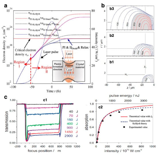
Figure 6.
The process of energy deposition and evolution under femtosecond laser irradiation. (a) The electron density ne(t) curve of KDP materials under the femtosecond laser irradiation based on Equation (13), λ = 800 nm, τ = 55 fs, I0 = 68 TW/cm2. Region I: photoionization, and Region II: avalanche ionization and formation of plasma []; (b) Deposition energy density distributions in dielectric materials predicted by nonlinear absorption model, τ = 50 fs, pulse energies and laser peak intensity of b1 100 nJ, 2.8 × 10¹³ W·cm−2, b2 250 nJ, 7 × 10¹³ W·cm−2, and b3 1000 nJ, 28 × 1013 W·cm−2, respectively; (c) Influence of plasma formation on laser irradiation with c1 the transmission of high-intensity femtosecond pulse laser irradiation as a function of laser focal position, and c2 the bulk absorption as a function of the laser pulse energy [].
In addition, there is a sharper drop in transmission at the near-front surface of dielectric materials in Figure 6c, and the greater the light intensity, the weaker the transmission performance and the stronger the absorption performance. Combined with the deposition energy density shown in Figure 6b, it is clear that the energy deposition density inside the material gradually increases with the increase of laser intensity due to the formation of plasma. Kandala et al. [] showed that there is the high concentration near the focal point and the end of the laser source due to the high laser intensity and the reflection of light by the plasma, respectively.
3.1.2. Irradiation of Short Pulse Laser
Although the formation of plasma under short-pulse lasers occurs as in the fs case, a significant difference is that energy deposition is time dependent. The absorption of energy by seed electrons occurs in the later period of short pulse laser irradiation, so the formation of plasma can be controlled by avalanche ionization, which is well confirmed in Figure 7a. Actually, a longer time contributes to effective plasma heating. Liu et al. [] observed the transient dynamics reaction of early plasma formation of KDP surface during nanosecond laser with the time resolved pump and probe (TRPP) technology, as shown in Figure 7c. The schematic diagram of time resolved pump and probe (TRPP) technology is shown in Figure 8. The plasma is gradually generated due to ionization, as shown in the dark region of Figure 7(c2). Due to the absorption of laser energy by the plasma, a temperature difference will generate between the air and the material, which results in the formation of shock wave in air. It is clear that with the expansion of the plasma, the shock wave becomes more and more significant, which also reflects the deposition process of early energy. The plasma region continuously grows along with the increase of the pump pulse.
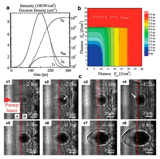
Figure 7.
The process of energy deposition and evolution of dielectric under short pulse laser irradiation. (a) Curve of the total electron density (Nt) and multiphoton produced electron density (Nm) with incident (fluence 10.1 J/cm2) and transmitted (fluence 9.7 J/cm2) laser pulse, τ = 100 ps []; (b) Evolution of theat of KDP as a function of the fluences F1ω and F3ω []; and (c) The transient images of plasma produced by early ionization with the delay between pump and probe pulse of −2.8 ns to 0.8 ns, the area A on the left side of the red dotted line is air, and B on the right side is KDP [].
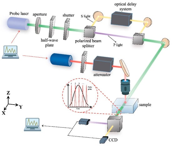
Figure 8.
Schematic diagram of time Resolved Pump and Probe (TRPP) technology [].
After the ionization is completed, the plasma formed in the early stage will slowly absorb most of the energy of the incident laser through inverse bremsstrahlung under the irradiation of the subsequent short pulse laser (ps–ns), which makes the plasma in the KDP crystal reach high temperature with a stable form. As shown in Figure 7b, the 1ω (1053 nm) radiation is more efficient than the 3ω (351 nm) for the plasma heating. The thermal conduction and hydrodynamics will also allow energy to be transferred away from the focus in the duration of input laser pulse []. The characteristics of the surrounding material such as absorption will be influenced by the transferred energy. Part of the absorbed and deposited laser energy will be transferred from electron to lattice of material gradually through the electron–phonon coupling technology in the picosecond timescale.
3.2. Effects of Surface Defects on Initial Energy Deposition of KDP Crystal
Due to the characteristic of KDP crystal materials, micro-nano-scale defects will be introduced into the surface when the single-point diamond ultra-precision fly-cutting (SPDF) is carried out on the surface of material. Various types of defects will exist on the surface of KDP crystal during the flying cutting. As a typical soft and brittle material, KDP crystal is more prone to produce brittle or plastic defects during processing [,]. Figure 9 shows the topography of KDP chip generated in the finishing stage.
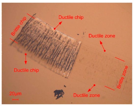
Figure 9.
Topography of the machined zone and chip in groove cutting test [].
Based on the characteristics of KDP crystal materials, Wang et al. [] further summarized all the defects that appeared on the surface of eight KDP components during processing and classified them into five categories, as shown in Figure 10.
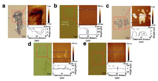
Figure 10.
Optical microscopy images of the five kinds of KDP surface defects. (a) Fracture pits; (b) Convex scratches; (c) Surface protuberances; (d) Cracks; and (e) Plastic scratches [].
Figure 10a shows the fracture pits defects usually with the widths of 20–200 μm and the depths of 2–6 μm. Figure 10b,c present different typical forms of protrusion damage. The cracks that are shown in Figure 10d with the lengths of 20–120 μm are also a kind of defect that occurs more frequently. Due to the characteristics of KDP, the typical plastic scratch defects are also often present during processing, as shown in Figure 10e. Wang et al. used the fluorescent emission detection technology to characterize the impact of KDP crystals on energy absorption under these five defects [,] and found that the fluorescence intensity of the defect-free area is significantly smaller than that of the defect area. Among the above defects, the fluorescence intensity of plastic scratches is greatly weaker than the other four defects. The surface defects in Figure 10a–d have a stronger absorption capacity than the defect-free KDP surface, and there will be more energy deposition near the defects.
Based on the investigation of the influence of surface defects on the LID of KDP crystal materials, Chen et al. [] showed that the light intensity is seriously affected by surface defects, and the characteristics of the light field modulation are strongly dependent on the geometry of defects. The modulation of the light field inside the material will cause an uneven distribution of light intensity, which in turn affects the difference in initial energy deposition inside the material. Therefore, it is very important to consider the effect of defects in the energy deposition stage of induced damage.
Duchateau et al. [] adopted a new mechanism based on thermally driven secondary point defect formation to simulate the process of energy absorption in precursor defects and surrounding materials.
The existence of precursor defects affects the absorption of energy by electrons, which in turn leads to a rapid increase in lattice temperature. As shown in Figure 11a, the temperature exhibits nonlinear behavior as a function of temporal and spatial (T and S) scales. The energy deposition takes place inside the material before the irradiation time of 0.5 ns. At the same time, the plasma formed inside the material expands at an almost constant rate, which makes the volume of energy deposition gradually increase, resulting in a significant increase in temperature. After 0.5 ns, the thermal explosion behavior is initiated, and the subsequent damage is caused.
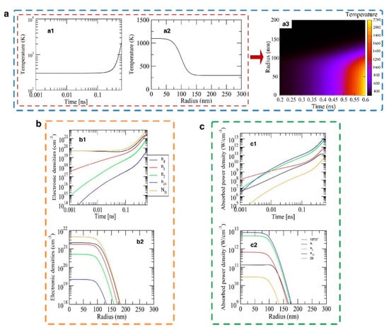
Figure 11.
The temporal and spatial (T and S) evolution of the predicted lattice temperature, the electronic densities, and the absorbed power density of the precursor. (a) Lattice temperature with a1 temporal scale, a2 spatial scale, and a3 the physical quantities depend both on space and time; (b) Electronic densities with b1 temporal scale and b2 spatial scale; and (c) Absorbed power density with c1 temporal scale and c2 spatial scale. The position of precursor of a1, b1, and c1 is in the center, and the actuation duration of a2, b2, and c2 is 500 ps [].
The effect of precursor defects on the initial energy deposition is well verified. Therefore, it is necessary to further explore the influence of defect morphology and size parameters on LIDT, and to find out the most threatening surface defects. Then, the methods for suppressing or repairing surface defects during the subsequent processing can be proposed to improve the LID resistance of KDP crystals. Some researchers summarized the various defects that introduced by SPDF technique on the surface of KDP crystal, and further explored the effects of different defects on energy deposition using simulation and experimental methods.
Cheng et al. [,] conducted the detailed investigations on surface cracks (Figure 12a) and scratches (Figure 12b) by establishing the simplified defect models. The surface scratches produced by flying cutting were simplified into circular and triangular to explore the light intensification distribution, as shown in Figure 12(a2,b2). At present, the light intensity enhancement factor (LIEF) was introduced internationally to characterize the intensity of distortion caused by defect inside the materials.
where Imax is the largest light intensity inside the KDP crystal with various defects, and I0 is the light intensity inside the KDP crystal with ideal surface. A series of ionization effects such as photoionization and avalanche ionization of the material will be more likely to occur when the LIEF reaches a certain critical value. The electron density will also increase significantly, resulting in more energy deposition inside the material. The finite-difference time-domain (FDTD) was used by Cheng to describe the light intensification distribution near the defects to reflect the difference in the initial energy deposited of different types of defects. FDTD algorithm can maturely deal with non-uniform and complex shapes of target radiation and electromagnetic scattering. In addition, it is very convenient to give a demonstration process of the advancement of each electromagnetic field with time. The light intensification can be solved and visualized. Visualization can clearly simulate the distortion caused by light intensification with the influence of defects, and FDTD will not be limited by the size of the simulated object, which brings convenience to the analysis [,].
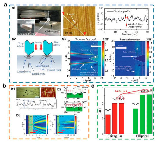
Figure 12.
Exploration of the influence of defects on energy deposition. (a) Cracks; (b) Scratches; and (c) Plastic scratches with brittle cracks. a1 and b1 are the topography images of defects; a2 and b2 are the simplified defect models; and a3 and b3 are the intensity distribution with simplified defect model simulated by finite-difference time-domain (FDTD) [,,].
It can be seen from Figure 12a,b that all the defects of KDP crystal will produce diffraction enhanced ripples with the irradiation of laser. Although the light intensity distribution caused by the triangular scratch is more complex and intense than that of the circular scratch due to the existence of manufacturing-induced front surface scratches, the LIEF of scratches is still smaller than that of cracks, which is similar to reference []. As shown in Figure 12c, Zhu et al. [] investigated the influence of surface scratches on the incident light intensity of KDP and found that once the brittle cracks appeared on the side of scratches, the LIEF would increase significantly, which also validated the hazards of brittle damage [].
Cheng and Yang et al. [] also noticed that cracks randomly existed on the front or rear surfaces of the KDP crystal, which would lead to different degrees of absorption of light intensity. The enhancement of light intensity induced by microcracks on the front surface is mainly caused by diffraction effect, standing wave effect and interference ripples effect. In contrast, the light intensity enhancement induced by the rear surface crack is mainly due to the total reflection or even double total reflection (DTR) effect of the incident laser at the crack wall. Although the light intensity distribution induced by the micro-cracks on the rear surface is relatively simple, a series of hot spots parallel to the rear surface were formed between the total reflected light wave and incident laser in the sub-surface of material, which will induce a strong phenomenon of light intensity enhancement, as indicated in Figure 12(a3). Thus, the energy deposition of laser on the rear surface is much more serious than the front surface.
Based on the investigation of the energy absorption capacity of different defects to the incident laser, Cheng et al. [] further summarized the trend of LIEF with the size parameters of surface crack defects, and then presented the degree of energy deposition.
It can be seen in Figure 13 that the LIEF induced by the micro-crack defects on the surface of the KDP crystal is not only related to the location of the micro-cracks and geometric structure parameters, but also the wavelength of the incident laser. The LIEF of KDP rear surface with conical cracks in Figure 13c is more susceptible to have larger values in the extremes under the influence of crack depth than other types of defects. In contrast, the LIEF of radial cracks and lateral cracks in Figure 13a,b will be larger on the front surface than on the rear surface. In general, the calculated LIEF shows a gradually increasing trend with the increase of size parameters. Therefore, the number, geometric parameters, and the positions of defects on the surface of crystal element can be controlled to ensure the laser damage resistance of KDP crystal elements.
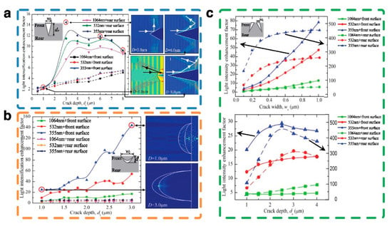
Figure 13.
Influence of size parameter of surface cracks on light intensity under the irradiation of 1064 nm, 532 nm, and 355 nm lasers. (a) Radial cracks; (b) Lateral cracks; (c) Conical cracks [].
Correspondingly, Cheng et al. [] used the R-on-1 laser irradiation mode to detect the surface LIDT of KDP crystals with different kinds of cracks, as shown in Figure 14. The cracks were established based on the exploration of references [,,].
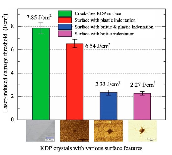
Figure 14.
Experimentally tested laser induced damage thresholds (LIDTs) for crack-free and flawed KDP surfaces [].
The results of experiments are consistent with the simulation data well. The existence of brittle cracks will greatly reduce the LIDT, which also verifies the rationality of FDTD algorithm simulation well.
To avoid the occurrence of brittle defects and a large amount of initial energy deposition, Wang et al. [] conducted a lot of research on the brittle-plastic transition during the processing, which provided a basis for obtaining the surface without brittle damage.
In the process of processing KDP materials, the first condition that needs to be satisfied is that the micro-cracks and craters formed in the brittle zone will not extend underneath the final surface, another condition is that the feed rate used in the cutting process should be small enough to ensure the fracture zone formed in the previous cutting can be completely removed by the subsequent process, as shown in Figure 15. These conditions can be expressed as Equation (14).
where Yc is the depth of any crack in the brittle domain, h is the distance between the origin of crack and the final surface, and x represents the horizontal distance between the original point of cutting and the original point of crack. R is the arc radius of tool, tc is the brittle plastic transformation depth, and f represents the feed per revolution.
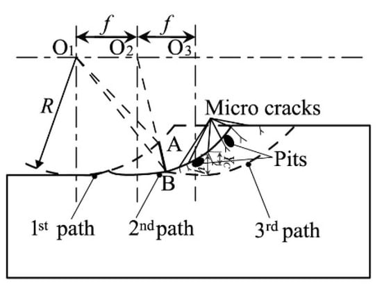
Figure 15.
Formation of crack-free surface in the processing by circular edge cutting tool [].
As long as the above conditions are met, the subsurface cracks generated in the brittle cutting zone will not continue to propagate, and subsequent processing can also guarantee the appearance of non-destructive machining surfaces as much as possible.
4. Simulation and Experimental Exploration of Laser-Induced Damage Behavior in the Later Stage
Under the irradiation of subsequent laser with different parameters, the local energy deposited in the early stage will be used as the energy source, which will cause thermal effects, phase changes and other phenomena in the material. The materials will eventually be damaged. Therefore, the pump probe method and hydrodynamics simulation techniques are viable solutions that crucial for describing the process between the initial energy deposition stage and the final damage crater formation.
4.1. Exploration of Transient Behavior at the Initiation of Damage
As shown in Section 3 of this review, during the energy deposition, the plasma gradually formed and further promoted the energy deposition. The deposition energy in the damage area provides necessary conditions for subsequent plasma expansion. Then, the pressure will appear. Actually, the correspondingly increased of pressure is the fluid dynamic effect of the energy deposition process [].
In addition, the process from the initial energy deposition stage to the final damage crater formation is quite varied under the subsequent irradiation of the ultrashort or short pulse laser [].
In general, the plasma formed inside the material will eject with the deposited energy. Ferrer et al. [] obtained plasma emission images with different pulse energies and pulse durations by using the lateral imaging system. It can be found that the energy deposition inside the dielectric material will be more significant under the irradiation of high-intensity ultra-short pulse laser. In addition, the diffusion range of the energy deposited inside is small, which will result in a high concentration of regional temperature. The plasma with all the deposited energy will eject from a small area of material rapidly. It can be seen in Figure 16a that the emitted plasma carries all the energy, and the temperature on the body of the material drops suddenly without any thermal conduction, which also visually reflects the phenomenon that the plasma will carry energy and eject from the interior of the material. The investigation of the shock wave generated by the instantaneous expansion and the emission of plasma have been described in reference []. The plasma will expand rapidly after absorbing energy, i.e., energy deposition, as shown in Figure 16b. Due to the severe temperature difference, the outward released plasma will induce the stress, which also contributes to the generation of shock waves. Combined with the images detected by TRPP technology in Figure 16, it can be reasonable to infer that that the shockwave in KDP will be generated by mechanical expansion rather than thermal expansion under the irradiation of ultra-short pulse laser [].
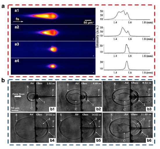
Figure 16.
The shockwave and plasma emission images of dielectric. (a) Plasma emission and the corresponding intensity cross sections along the z-axis. a1, a2, and a3 obtained for pulses of energies of 9.6 μJ and pulse durations of 100 fs, 250 fs, and 550 fs, respectively. In a4, the pulse duration is 250 fs and the pulse energy is 4 μJ; (b) The shadowgraphs of femtosecond laser ablation of dielectric recorded at six different delay times by TRPP, where S: shockwave front; C: contact front; 1: the first stress wave front; 2: the second stress wave front; and F: filament. The energy fluence on the target surface is 40 J/cm2, and laser pulse is 50 fs [,].
In contrast, the irradiation of the short pulse laser ensures the thermal conduction. Unlike the sudden emission of plasma under the irradiation of ultra-short pulse laser, the emission process of plasma under the irradiation of short pulse laser involves the parameters such as temperature and stress.
At the end of the plasma formation process, the temperature and pressure in this region are significantly higher than that of the surroundings. When the heat transferred from the center of the laser beam to the surrounding area gradually, a non-uniform temperature field will form inside the crystal material, causing a temperature gradient inside the material []. The existence of temperature gradient inside the crystal will cause compressive stress in the material. The resulting compressive stress also makes the thermal expansion of the irradiation area on the upper side of the absorption layer larger than the expansion on the lower side. With the increase of the temperature in the irradiation area, the stress state in the material will also increase, which will result in the stress gradients. The resulting pressure gradients will lead to the formation of a blast wave that propagates into the background gas. It is worth noting that the pressure gradient in the vicinity of the precursor defect will be larger due to the large amount of energy deposition.
A series of processes about the gradual initiation of damage under short-pulse laser irradiation were explored. Many models were built for the gradual initiation of damage. The equivalent explosion simulation model of the laser-induced damage process shows the ejection phenomenon under different explosion conditions with the smoothed particle hydrodynamics (SPH) method. Yang et al. [,] established the multi-physics coupling model for the lateral crack defect, which further verified the explosion process of reference [].
In order to describe the transient characteristics of the damage initiation accurately, Wang et al. [] introduced the explosion damage threshold (EDT) when exploring the process of damage initiation. Under the irradiation of the laser, the plasma explosion will occur, and the substance ejection will appear near the laser irradiation point once the energy reaches the threshold. This phenomenon can last for several microseconds until the damage pit is finally formed. It can be seen that the damage is formed at a certain angle both in Figure 17(a1,a2). In addition, with the increase of the irradiation time, the damage pits show the trend of expanding from the section of point to cone, with different degrees of expansion in both the horizontal and vertical directions, and eventually form the bowl-shaped damage pits. Therefore, further exploration in terms of damage expansion is needed to study other significant phenomena that may affect the damage formation.
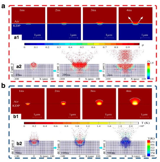
Figure 17.
Evolution process of damage initiation. (a) Simulated damage crater formation process in the laser damage area; (b) Simulated temperature variation in the laser damage area [,].
Figure 17b shows the temperature variation (parameter T in the model) distribution of the explosion zone with time during nanosecond laser irradiation. It can be seen that the cross-section area of high-temperature region gradually expands. Figure 17(b2) shows the phase state of the ejected material at different times delay clearly.
As shown in Figure 17(b1), the temperature at the laser irradiation point is the highest, exceeding the melting point of KDP crystal, which will cause the material in the area to be gaseous state. Since the nanosecond laser irradiation time ensures the thermal conduction, the temperature of the central area will gradually conduct to the vicinity and expand, the thermal damage area will show a growth. Actually, the expansion rate of the high temperature region is particularly severe in the gaseous state, which will lead to significant thermal stress near the damage pit.
In addition, with reference to Figure 17b, high-temperature gaseous substances were ejecting outward during the initiation of damage. In the case of the increase of time delays, it can be seen that in the later physical process of the material being irradiated by laser, the gaseous substance in the earlier stage was converted into a multi-phase mixture composed of solid, gaseous, and liquid states of KDP. This phenomenon is consistent with the substance ejection behavior experimentally that observed in the laser damage processes reported in reference []. With the further development of the ejection process, almost all the ejected particles were observed to exist in solid form. Wang et al. indicated that the ejection of solid particles starts at about the 100 ns delay, which also means the initiation of mechanical damage.
In order to investigate the thermal stress and mechanical stress caused by plasma during explosion, the shock wave evolution process that showed with TRPP technology and simulation means are also used to characterize the energy conversion and the process between the initial energy deposition stage and the final damage crater formation indirectly.
The propagation of air shockwave was directly extracted from the results of FEM (Finite Element Method) simulation [,], as shown in Figure 18(a1–a3). It can be seen that the attenuation of the shockwave speed follows the exponential law, which has been summarized in the Figure 18(a4). In addition, Figure 18(a7) shows the shockwave velocity well by experiments. It is clear that the shockwave velocity increase with the increment of laser fluences. The propagation paths of shockwave in Figure 18(a5,a6) and Figure 18b are consistent, which also validates the correctness of the simulation results in Figure 18(a1–a3).
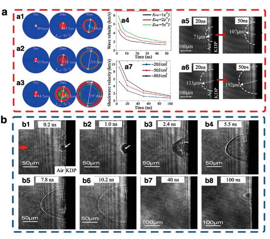
Figure 18.
The evolution diagram of shock wave. (a) Air shockwave propagation under different explosion conditions. a1, a2, and a3 are the simulated condition that Eexp = 1e−9, Eexp = 2e−9, and Eexp = 5e−9, respectively, with a4 the influence of explosion energy on the shockwave velocity. a5 and a6 are the time-resolved image series of laser-induced KDP surface damage process with fluences 20 J/cm2 and 50 J/cm 2, respectively, and a7 the shockwave velocity [,]; (b) The propagation of shockwave in pump laser pulse duration from 0.2 ns to 100 ns [].
Based on the above simulation of damage initiation process and the detection of TRPP technology under nanosecond laser irradiation, it can be inferred that thermal stress plays an important role in the process of damage initiation and damage forming. In order to verify the influence that thermal stress plays in damage forming, a series of exploration had been conducted by researchers.
Combined with the properties of KDP crystals, it can be found that a non-uniform temperature field will form inside the crystal material when the heat transferred from the center of the laser beam to the area of the surrounding area gradually, causing a temperature gradient inside the material. The existence of temperature gradient inside the crystal will cause compressive stress in the material. In order to explore the magnitude and effect of stress more concisely, Zeng et al. [] conducted further investigation and found a second wave would be generated inside the fused silica due to the high back-pressure of the laser-generated plasma, as shown in Figure 19b. In addition, Demos et al. [] explored and compared the kinetic behavior of KDP and fused silica under laser irradiation. It is clear that the expansion of shockwaves in air in Figure 19a is quite similar in both materials at the same delay time, which also suggests that the initial energy deposited in a single laser-induced breakdown event was roughly the same.
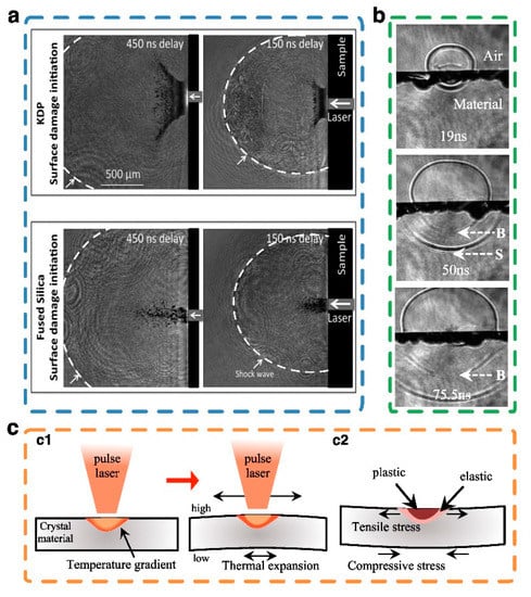
Figure 19.
The effect and distribution of stress. (a) Comparison of the shockwave in fused silica and KDP. The shockwave propagating is denoted by an arrow []; (b) Propagation of shockwaves in materials. The shock front (S), back-pressure induced shock wave (B); (c) Analysis of the stress action on crystal material under laser irradiation []. c1 The distribution of thermal stress due to temperature gradient and expansion; c2 The deformation of crystal materials under tensile stress [].
Although there are relatively few observations on the internal response of KDP crystals at present, it is reasonable to infer that the back-pressure induced shockwave with a propagation pattern approximated shown in Figure 19b will also occur inside KDP crystals based on the principle analysis of thermal stress on KDP crystals and the comparative exploration of shockwave between fused silica and KDP. However, considering the anisotropy and soft brittleness of the KDP crystal, the shape and directionality of the back-pressure shockwave generated inside the material need to be further studied and explored.
In later stages, the compressive stress generated in the early stages also makes the thermal expansion of the irradiation area on the upper side of the absorption layer larger than the expansion on the lower side. With the increase of the temperature in the irradiation area, the stress state in the material will increase, and the material is completely in an elastic deformation state.
For crystal materials, plastic deformation will occur when the temperature of the irradiated area exceeds the threshold that the material can withstand. Dowden et al. [,] proposed that the existence of plastic deformation will relieve the stress state. At last, the internal temperature of the crystal material will gradually cool down with the end of laser irradiation, while the generated compressive stress can be relaxed and convert to tensile stress [,]. KDP crystal materials will produce birefringence during laser irradiation due to its anisotropic properties. Owing to the existence of the birefringence effect, the incident laser will be decomposed into two beams with different characteristics. The transmission and focusing characteristics of the incident laser will also be changed accordingly, which will cause an asymmetric distribution of thermal stress in crystals [,,]. Therefore, the residual stress is easily generated during the relaxation of stress in elastic and plastic areas. Figure 19(c2) [] shows the deformation process of crystal materials under tensile stress.
In general, based on the investigation of the transient behavior of damage initiation and the evolution of shock wave, it can be found that the rapid plasma injection under the irradiation of ultra-short pulse laser will cause mechanical damage. However, there is a thermal conduction process under the irradiation of short pulse laser, which will lead to the coexistence of thermal stress and mechanical stress, which has an effect on the material.
4.2. Morphological Characteristics of Laser-Induced Damage in the Later Stage
Based on the exploration of the transient behavior at the initiation of damage, the main damage morphology under different pulses can be shown in Figure 20.
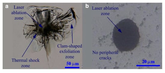
Figure 20.
Typical morphological comparison of the laser damage sites on KDP crystal surfaces induced by short and ultra-short laser pulses. (a) FWHM (Full Wave at Half Maximum) = 6.9 ns; (b) FWHM = 28 fs [].
The laser energy deposited inside the crystal material can be transferred to the surrounding material area through thermal conduction under the irradiation of short laser. According to the analysis of the thermal conduction in Section 4.1., there will be stress near the erosion pit. Actually, the brittle crystal materials have strong fracture toughness against compressive stress, but much smaller against tensile stress. As a result, the cracks will occur around the molten pit if the tensile stress exceeds the fracture toughness of KDP crystals. However, KDP crystal materials are anisotropic, which will lead to the generation of non-directional cracks. Therefore, the damage process of the material is accompanied by melting, crack propagation et al., and the final morphology of the damage point is also more complicated, as shown in Figure 20a []. The experimental investigations of short pulse laser induced damage have verified the rationality of the damage mechanism that discussed in the above sections well. In contrast, the morphology of the damage pit under ultra-short pulse laser irradiation in Figure 20b is obviously different from that of short pulse laser irradiation. The laser energy deposited inside the crystalline material is too late for thermal conduction to occur due to the ultra-short pulse period. In addition, the morphology of the damage pit that shown in Figure 20b is a good verification of the correctness of the inference that shockwave is generated by mechanical expansion for KDP under ultrashort pulse irradiation in Section 4.1. As a result, the laser damage only occurred in the local high-temperature plasma area near the focal point of the laser spot, and there was no obvious cracking around the damage point. In the study of nanosecond laser induced damage, Liu et al. [] found that the incident laser fluence has an effect on the morphology and size of the damage of KDP crystal. Based on the observation of damage morphology, these damages can be divided into three typical types: crack, shell, and crater, as shown in Figure 21.
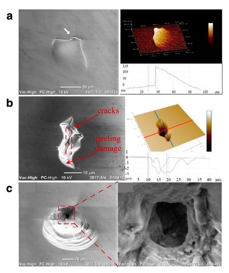
Figure 21.
Microscopic images of the typical damage morphology. (a) Crack, (b) shell, and (c) crater. Λ = 351 nm, pulse duration = 5 ns [].
The crack-type damage always generates on the surface without any connection with the thermal explosion and fracturing inside the bulk under laser fluence smaller than 7.5 J/cm2. Liu et al. proposed that crack damage is caused by the residual stress during processing. Once the laser fluence more than 7.5 J/cm2 is used to irradiate KDP crystal material, shell-type damage, and crater-type damage begin to appear. Among them, the mechanism of shell damage is the same as that of crack damage, which is caused by the residual stress during processing. Shell damage accounts for 80% of the total damage, while crater damage is mainly caused by a large amount of thermal absorption and conduction due to the residual defects in the previous processing. Based on the analysis of the morphology and composition of the damage surface, the morphology characteristics of LID has been further supplemented in Figure 22.
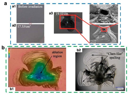
Figure 22.
Typical morphology of the laser-induced damage. (a) Damage craters under the irradiation of nanosecond laser (λ = 355 nm) with a1 before irradiation, a2 fluences (17.3 J/cm2), and a3 fluences (19.5 J/cm2) shows the central core []; (b) Damage under λ = 355 nm, and 6.4 ns pulse duration with b1 reflection 3D scan image and b2 transmission 3D scan image [].
It can be seen in Figure 22 that the damage pit presents a cone-shaped crater with a melted core region and fractured periphery. The cracks stretch outward. It is clear that the laser heating and material structural deformation are coupled to each other and then contribute to the LID of KDP crystal. Hou et al. [] proposed that the temperature gradient between the thermal affected region and the surrounding normal crystal material will cause a bursting random “clam-shaped” peeling layer with unpredictable directions around the damage point due to the soft, brittle, and the highly anisotropic characteristics of KDP crystal. In addition, the nonlinear absorption characteristics of the initial defects of the KDP crystal also have a great influence on the subsequent damage with the increase of laser fluence. The more energy the material absorbs, the greater the energy of the thermal explosion shock wave. As a result, the damage will be more serious, and the number and size of crater damage will become larger. It is important to observe the initiation of damage in real-time under the irradiation of high fluence.
4.3. Outlook of the Prediction of Damage Threshold
The three stages from the initiation to the finalization of LID (i.e., energy deposition, damage initiation, and damage forming) was described clearly in the above sections to understand the mechanism of LID and to predict the LIDT more accurate. Actually, the deposition of energy will cause the initiation of damage once it reaches a certain degree. Based on the analysis of the initial energy deposition under the irradiation of laser, it can be found that all the methods of embodying the peak energy the material can withstand are not intuitive. The electron density curve of KDP materials and the transmission or absorption of the incident laser can only reflect the trend of damage, which is not the great methods to predict the damage threshold. The technology of TRPP in Section 3.1.2. captures the momentary dynamic behavior of damage initiated on KDP materials. However, it is still not enough to improve the anti-laser damage ability of KDP crystal solely rely on the prediction of damage trends. In addition, some surface defects tend to be leaved on the surface of KDP after processing. Under these conditions, accurate and intuitive prediction of damage threshold remains a challenge.
To overcome this difficulty, our research group has carried out some relevant research on the prediction of LIDT. In the early stage, Chen et al. [,] used the FTDT algorithm to explore the phenomenon of light intensity modulation inside the material under the analysis of the electric field. Based on the exploration of the damage trend, the multi-physics and electric field coupling technology was discovered and applied to the prediction of the LIDT of KDP crystals with different cracks defects in reference []. The multi-physics coupling technology reveals the mechanism of damage more comprehensively and gives the detailed damage thresholds and damage mechanism intuitively, as shown in Figure 23.
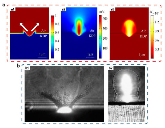
Figure 23.
Transient dynamic behavior induced by laser damage on the surface of KDP crystal with conical crack defect. (a) Multi-physics coupling simulation result with a1 crater morphology, a2 vapor velocity distribution, and a3 temperature distribution of local laser damage area; (b) Experimental images captured by the system in the laser damage micro-region with b1 material ejection and b2 plasma expansion [].
In addition, in order to investigate the LID of KDP crystals more comprehensively, our research group subsequently carried out the corresponding verification of damage mechanism and damage threshold in engineering. The damage repair devices [,] as well as repair strategies [,], were explored with a view to achieving the significance of predicting the damage threshold. Figure 24 demonstrates the designed repair device and the repair process of damaged pits of our research group.
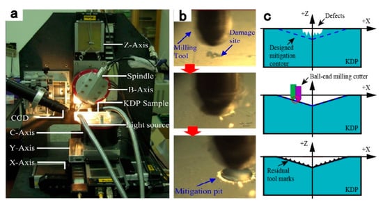
Figure 24.
Micro-milling set-up developed for the repairment of damage on KDP crystal. (a) Overall configuration of the 5-axis vertical spindle machine tool; (b) The repairing process []; (c) Schematic of the generation process of tool marks in the micro ball-end milling repair process of KDP optics [].
For the design of the repair strategies, Chen [,] and Liu et al. [] conducted various measurements on LIDT to ensure that the repair work is effective in raising the LIDT of KDP crystal. Both the experimental and simulation data well demonstrate the reasonableness of the designed restoration strategy, as shown in Figure 25.
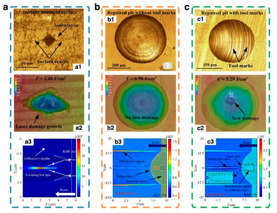
Figure 25.
Morphologies of the various KDP surfaces before (a1, b1, and c1) and after (a2, b2, and c2) 355 nm-laser pulse irradiation. (a) Initial crack damaged surfaces; (b) Repaired pit without tool marks; (c) Repaired pit with tool marks. a3, b3, and c3 are the light intensity enhancement factor (LIEF) distribution [,].
However, based on the consideration of the different effects of various initial defects of KDP materials on energy deposition, a more comprehensive application of multi-physical coupling techniques is needed.
5. Summary and Outlook
In summary, the emergence of chirped pulse amplification technology has greatly promoted the development and application of rapid ignition in laser-driven inertial confinement fusion. However, it is necessary to consider the limitations caused by the low LIDT of core optical components such as KDP crystals when constructing a laser system with high output power density. The impurities in the process of the formation of crystal materials can be controlled greatly due to the advance of technology. However, the occurrence of defects or scratches on surface is inevitable during the application of crystalline optical materials. As a result, it is very necessary to understand the intrinsic damage mechanism of crystal materials under the laser irradiation. Only understanding the mechanism of laser induced damage of the crystal material, can the comprehensive repair of the damaged points be proceeded. The accurate mitigation can ensure that there is no residual mechanical or thermal stress to fail the repair.
To address this problem, the principles of LID has been reviewed clearly. The mechanism is mainly summarized as impurity thermal damage and ionization damage. Then, the process from the initiation to the finalization of LID has been divided into three stages (i.e., energy deposition, damage initiation, and damage forming) to ensure the understanding of LID. It is worth noting that the three stages are complementary to each other. The energy deposition inside the KDP crystal material is serious under high-intensity laser fluence, especially when there are various processing defects remaining on the surface of KDP. The influence of various initial defects on the forming of damage also has great difference. In addition, different degrees of initial energy deposition under the subsequent irradiation with different wavelengths and laser fluence will also have a great impact on damage forming.
The damage has various morphology. It is mainly composed of cracks, bursts, and melting pit under short pulse laser irradiation, which also means the thresholds for damage initiation under various types of initial defects are different. Thus, the transient dynamic behavior of multi-physics coupling simulation and some experiments are still needed to further explore to determine the threshold in different situations.
Author Contributions
Conceptualization, M.C. and W.D.; methodology, M.C.; investigation, H.Y. and Q.L.; validation, J.C.; writing—original draft preparation, W.D.; writing—review and editing, M.C., W.D., and J.C.; Funding acquisition, M.C. and J.C. All authors have read and agreed to the published version of the manuscript.
Funding
We acknowledge the support of Science Challenge Project [No. TZ2016006-0503-01]; the National Natural Science Foundation of China [Nos. 51775147, 51705105]; the Young Elite Scientists Sponsorship Program by CAST [No. 2018QNRC001]; the China Postdoctoral Science Foundation [Nos. 2017M621260, 2018T110288]; the Heilongjiang Postdoctoral Fund [No. LBH-Z17090]; the Fundamental Research Funds for the Central Universities [No. HIT.NSRIF.2019053]; and the Self-Planned Task Foundation of State Key Laboratory of Robotics and System (HIT) of China [No. SKLRS201718A, SKLRS201803B].
Conflicts of Interest
The authors declare that they have no conflict of interest.
References
- Betti, R.; Hurricane, O.A. Inertial-confinement fusion with lasers. Nat. Phys. 2016, 12, 435–448. [Google Scholar] [CrossRef]
- Manes, K.R.; Spaeth, M.L.; Adams, J.J.; Bowers, M.W.; Bude, J.D.; Carr, C.W.; Conder, A.D.; Cross, D.A.; Demos, S.G.; Di Nicola, J.M.G.; et al. Damage Mechanisms Avoided or Managed for NIF Large Optics. Fusion Sci. Technol. 2016, 69, 146–249. [Google Scholar] [CrossRef]
- Moses, E.I.; Lindl, J.D.; Spaeth, M.L.; Patterson, R.W.; Sawicki, R.H.; Atherton, L.J.; Baisden, P.A.; Lagin, L.J.; Larson, D.W.; MacGowan, B.J.; et al. Overview: Development of the national ignition facility and the transition to a user facility for the ignition campaign and high energy density scientific research. Fusion Sci. Technol. 2016, 69, 1–24. [Google Scholar] [CrossRef]
- Huang, J.; Wu, Z.; Wang, F.; Liu, H.; Sun, L.; Zhou, X.; Ye, X.; Deng, Q.; Jiang, X.; Zheng, W.; et al. Initial Damage and Damage Growth of KDP Crystals Induced by 355 nm Pulse Laser. Cryst. Res. Technol. 2018, 53, 1700269. [Google Scholar] [CrossRef]
- Hou, N.; Zhang, L.; Zhang, Y.; Zhang, F. On the Ultra-Precision Fabrication of Damage-Free Optical KDP Components: Mechanisms and Problems. Crit. Rev. Solid State Mater. Sci. 2019, 44, 283–297. [Google Scholar]
- Hurricane, O.A.; Callahan, D.A.; Casey, D.T.; Celliers, P.M.; Cerjan, C.; Dewald, E.L.; Dittrich, T.R.; Döppner, T.; Hinkel, D.E.; Hopkins, L.F.B.; et al. Fuel gain exceeding unity in an inertially confined fusion implosion. Nature 2014, 506, 343–348. [Google Scholar] [CrossRef]
- Gopalaswamy, V.; Betti, R.; Knauer, J.P.; Luciani, N.; Patel, D.; Woo, K.M.; Bose, A.; Igumenshchev, I.V.; Campbell, E.M.; Anderson, K.S.; et al. Tripled yield in direct-drive laser fusion through statistical modelling. Nature 2019, 565, 581–586. [Google Scholar] [CrossRef]
- Shcheblanov, N.S.; Itina, T.E. Femtosecond laser interactions with dielectric materials: Insights of a detailed modeling of electronic excitation and relaxation processes. Appl. Phys. A 2013, 110, 579–583. [Google Scholar] [CrossRef]
- Pritula, I.; Kolybayeva, M.; Salo, V.; Puzikov, V. Defects of large-size KDP single crystals and their influence on degradation of the optical properties. Opt. Mater. 2007, 30, 98–100. [Google Scholar] [CrossRef]
- Liu, H.J.; Huang, J.; Wang, F.R.; Zhou, X.D.; Ye, X.; Zhou, X.Y.; Sun, L.X.; Jiang, X.D.; Sun, Z.; Zheng, W.G. Subsurface defects of fused silica optics and laser induced damage at 351 nm. Opt. Express 2013, 21, 12204–12217. [Google Scholar]
- Lapointe, J.; Bérubé, J.-P.; Ledemi, Y.; Dupont, A.; Fortin, V.; Messaddeq, Y.; Vallée, R. Nonlinear increase, invisibility, and sign inversion of a localized fs-laser-induced refractive index change in crystals and glasses. Light Sci. Appl. 2020, 9, 64. [Google Scholar] [CrossRef] [PubMed]
- Duchateau, G. Simple models for laser-induced damage and conditioning of potassium dihydrogen phosphate crystals by nanosecond pulses. Opt. Express 2009, 17, 10434–10456. [Google Scholar] [CrossRef] [PubMed]
- De Yoreo, J.J.; Burnham, A.K.; Whitman, P.K. Developing KH2PO 4 and KD2PO 4 crystals for the world’s most power laser. Int. Mater. Rev. 2002, 47, 113–152. [Google Scholar] [CrossRef]
- Demos, S.G.; Negres, R.A.; Raman, R.N.; Rubenchik, A.M.; Feit, M.D. Material response during nanosecond laser induced breakdown inside of the exit surface of fused silica. Laser Photon. Rev. 2013, 7, 444–452. [Google Scholar] [CrossRef]
- Huang, J.; Liu, H.; Wang, F.; Ye, X.; Sun, L.; Zhou, X.; Wu, Z.; Jiang, X.; Zheng, W.; Sun, D. Influence of bulk defects on bulk damage performance of fused silica optics at 355 nm nanosecond pulse laser. Opt. Express 2017, 25, 33416–33428. [Google Scholar] [CrossRef]
- Reyne, S.; Duchateau, G.; Hallo, L.; Natoli, J.Y.; Lamaignere, L. Multi-wavelength study of nanosecond laser-induced bulk damage morphology in KDP crystals. Appl. Phys. A 2015, 119, 1317–1326. [Google Scholar] [CrossRef]
- Tian, Y.; Han, W.; Cao, H.B.; Li, F.Q.; Feng, B.; Zhao, J.P.; Zheng, K.X.; Zhu, Q.H.; Zheng, W.G. Characteristics of Laser-Induced Surface Damage on Large-Aperture KDP Crystals at 351 nm. Chin. Phys. Lett. 2015, 32, 027801. [Google Scholar] [CrossRef]
- Cheng, J.; Chen, M.; Liao, W.; Wang, H.; Wang, J.; Xiao, Y.; Li, M. Influence of surface cracks on laser-induced damage resistance of brittle KH2PO4 crystal. Opt. Express 2014, 22, 28740–28755. [Google Scholar] [CrossRef]
- Bude, J.; Miller, P.; Baxamusa, S.; Shen, N.; Laurence, T.; Steele, W.; Suratwala, T.; Wong, L.; Carr, W.; Cross, D.; et al. High fluence laser damage precursors and their mitigation in fused silica. Opt. Express 2014, 22, 5839–5851. [Google Scholar] [CrossRef]
- Wang, S.; Wang, J.; Xu, Q.; Lei, X.; Liu, Z.; Zhang, J. Influences of surface defects on the laser-induced damage performances of KDP crystal. Appl. Opt. 2018, 57, 2638–2646. [Google Scholar] [CrossRef]
- Ogorodnikov, I.N.; Yakovlev, V.; Shul’Gin, B.V.; Satybaldieva, M.K. Transient optical absorption of hole polarons in ADP (NH4H2PO4) and KDP (KH2PO4) crystals. Phys. Solid State 2002, 44, 880–887. [Google Scholar] [CrossRef]
- Guo, D.C.; Jiang, X.; Huang, J.; Wang, F.R.; Liu, H.J.; Xiang, X.; Yang, G.X.; Zheng, W.G.; Zu, X. Effects of γ-ray irradiation on optical absorption and laser damage performance of KDP crystals containing arsenic impurities. Opt. Express 2014, 22, 29020–29030. [Google Scholar] [CrossRef] [PubMed]
- Guillet, F.; Bertussi, B.; Lamaignere, L.; Leborgne, X.; Minot, B. Preliminary results on mitigation of KDP surface damage using the ball dimpling method. In Proceedings of the Boulder Damage Symposium XXXIX: Annual Symposium on Optical Materials for High Power Lasers, Boulder, CO, USA, 18 December 2007; Volume 6720, p. 672008. [Google Scholar]
- Chen, L.Z.; Xiang, Z.; Jing, C.Y. Simulation study on the influence of subsurface deficiency on fused silica laser damage threshold. In SPIE/SIOM Pacific Rim Laser Damage: Optical Materials for High-Power Lasers; Shanghai, China, 9 July 2013, SPIE Press: Bellingham, WA, USA; Volume 8786.
- Keldysh, L.V. Ionization in the field of a strong electromagnetic wave. Sov. Phys. JETP. 1965, 20, 1307–1314. [Google Scholar]
- Sparks, M.S.; Duthler, C.J. Theoretical Studies of High-Power Ultraviolet and Infrared Materials; Xonics Inc.: Van Nuys, CA, USA, 1974; pp. 78–114. [Google Scholar]
- Jing, X.; Shao, J.; Zhang, J.; Jin, Y.; He, H.; Fan, Z. Calculation of femtosecond pulse laser induced damage threshold for broadband antireflective microstructure arrays. Opt. Express 2009, 17, 24137–24152. [Google Scholar] [CrossRef] [PubMed]
- Feit, M.D.; Rubenchik, A.M. Laser intensity modulation by nonabsorbing defects. In Proceedings of the 28th Annual Symposium on Optical Materials for High Power Lasers—Boulder Damage Symposium, Boulder, CO, USA, 7–9 October 1997; Volume 2966, pp. 475–480. [Google Scholar]
- Cheng, J. Effect of Surface Micro-Defects and Their Repairing on Laser Damage Resistance of KDP Crystal. Ph.D. Thesis, Harbin Institute of Technology, Harbin, China, 2016. [Google Scholar]
- Chen, M.J.; Chen, K.N.; Li, M.Q. FDTD analysis of the effect of micro-waviness on near-field light intensity distribution in KDP crystal. Opto-Electron. Eng. 2010, 37, 19–23. [Google Scholar]
- Manenkov, A.A. Fundamental mechanisms of laser-induced damage in optical materials: Today’s state of understanding and problems. Opt. Eng. 2014, 53, 10901. [Google Scholar] [CrossRef]
- Jing, X.; Tian, Y.; Zhang, J.; Chen, S.L.; Jin, Y.; Shao, J.; Fan, Z. Modeling validity of femtosecond laser breakdown in wide bandgap dielectrics. Appl. Surf. Sci. 2012, 258, 4741–4749. [Google Scholar] [CrossRef]
- Stuart, B.C.; Feit, M.D.; Herman, S.; Rubenchik, A.M.; Shore, B.W.; Perry, M. Optical ablation by high-power short-pulse lasers. J. Opt. Soc. Am. B Opt. Phys. 1996, 13, 459–468. [Google Scholar] [CrossRef]
- Miki, H.; Fukunaga, R.; Asakuma, Y.; Maeda, K.; Fukui, K. Distribution of dye into KDP crystals in a continuous MSMPR crystallizer. Sep. Purif. Technol. 2005, 43, 77–83. [Google Scholar] [CrossRef]
- Chen, M.J.; Pang, Q.L.; Liu, X.Y. Finite element analysis on influence of micro-nano machined surface impurity on optical performance. High Power Laser Part. Beams 2008, 20, 1182–1186. [Google Scholar]
- Hirota, S.; Miki, H.; Fukui, K.; Maeda, K. Coloring and habit modification of dyed KDP crystals as functions of supersaturation and dye concentration. J. Cryst. Growth 2002, 235, 541–546. [Google Scholar] [CrossRef]
- Jing, C.; Guo, X.; Zhang, T.; Chen, L. Analysing the Influence of Subsurface Impurity on Laser-induced Damage Threshold of KDP Crystal. In Proceedings of the 2016 4th International Conference on Machinery, Materials and Information Technology Applications, Xi’an, China, 10–11 December 2016; pp. 45–50. [Google Scholar]
- Koldunov, M.F.; Manenkov, A.A. Theory of laser-induced inclusion-initiated damage in optical materials. Opt. Eng. 2012, 51, 121811. [Google Scholar] [CrossRef]
- Manenkov, A.A. Fundamental mechanisms of laser-induced damage in optical materials: Understanding after 40 years of research. In Proceedings of Boulder Damage Symposium XL Annual Symposium on Optical Materials for High Power Lasers, Boulder, CO, USA, 30 December 2008; Volume 7132, p. 713202. [Google Scholar]
- Rong, Q.; Yong, J.; Decheng, G.; Jinfang, S.; Cui, L.; Cheng, Y.; Qiang, Z.; Wei, H.; Jin, H. Laser-induced damage in fused silica under multi-wavelength simultaneous laser irradiation. High Power Laser Part. Beams 2020, 32, 66–70. [Google Scholar]
- Zhao, L.; Cheng, J.; Chen, M.; Yuan, X.; Liao, W.; Wang, H.; Liu, Q.; Yang, H. Toward little heat-affected area of fused silica materials using short pulse and high power CO2 laser. Results Phys. 2019, 12, 1363–1371. [Google Scholar] [CrossRef]
- Mu, X.M.; Wang, B.; Wang, S.L.; Xu, X.; Sun, X.; Gu, Q.T. Effect of Ca2+ on the damage threshold of KDP single crystals. J. Synth. Cryst. 2008, 37, 1097–1116. [Google Scholar]
- Bercegol, H.; Bonneau, F.; Bouchut, P.; Combis, P.; Gallais, L.; Lamaignère, L.; Natoli, J.-Y.; Rullier, J.-L.; Vierne, J. Comparison of numerical simulations with experiment on generation of craters in silica by a laser. In Laser-Induced Damage in Optical Materials: Proceedings of the 2002 and 7th International Workshop on Laser Beam and Optics Characterization, Boulder, CO, USA, 30 May 2003; SPIE Press: Bellingham, WA, USA, 2003; Volume 4932, pp. 297–308. [Google Scholar]
- Carr, C.W.; Bude, J.; Demange, P. Laser-supported solid-state absorption fronts in silica. Phys. Rev. B 2010, 82, 184304. [Google Scholar] [CrossRef]
- Koldunov, M.F.; Manenkov, A.A.; Pocotilo, I.L. Multishot Laser Damage in Transparent Solids: Theory of Accumulation Effect. In Proceedings of the 27th Annual Boulder Damage Symposium: Laser-Induced Damage in Optical Materials, Boulder, CO, USA, 14 July 1995; Volume 2428, pp. 653–667. [Google Scholar]
- Balling, P.; Schou, J. Femtosecond-laser ablation dynamics of dielectrics: Basics and applications for thin films. Rep. Prog. Phys. 2013, 76, 036502. [Google Scholar] [CrossRef]
- Carr, C.W.; Radousky, H.B.; Rubenchik, A.M.; Feit, M.; Demos, S.G. Localized Dynamics during Laser-Induced Damage in Optical Materials. Phys. Rev. Lett. 2004, 92, 87401. [Google Scholar] [CrossRef] [PubMed]
- Carr, C.W.; Feit, M.D.; Rubenchik, A.M.; De Mange, P.; Kucheyev, S.O.; Shirk, M.D.; Radousky, H.B.; Demos, S.G. Radiation produced by femtosecond laser–plasma interaction during dielectric breakdown. Opt. Lett. 2005, 30, 661–663. [Google Scholar] [CrossRef]
- Carr, C.W.; Radousky, H.B.; Demos, S.G. Wavelength Dependence of Laser-Induced Damage: Determining the Damage Initiation Mechanisms. Phys. Rev. Lett. 2003, 91, 127402. [Google Scholar] [CrossRef]
- Mevel, E.; Breger, P.; Trainham, R.; Petite, G.; Agostini, P.; Migus, A.; Chambaret, J.-P.; Antonetti, A. Atoms in strong optical fields: Evolution from multiphoton to tunnel ionization. Phys. Rev. Lett. 1993, 70, 406–409. [Google Scholar] [CrossRef] [PubMed]
- Rethfeld, B. Free-Electron Generation in Laser-Irradiated Dielectrics. Contrib. Plasma Phys. 2007, 47, 360–367. [Google Scholar] [CrossRef]
- Schaffer, C.B.; Brodeur, A.; Mazur, E. Laser-induced breakdown and damage in bulk transparent materials induced by tightly focused femtosecond laser pulses. Meas. Sci. Technol. 2001, 12, 1784–1794. [Google Scholar] [CrossRef]
- Walser, A.D.; Bouselhami, A.; Yan, M.; Dorsinville, R. Nonlinear Optical Absorption and Refraction in Optical Crystals at 355 Nm. In Proceedings of SPIE’s International Symposium on Optical Science, Engineering, and Instrumentation, Denver, CO, USA, 28 June 1999; Volume 3793, pp. 157–162. [Google Scholar]
- Demos, S.G.; Demange, P.; Negres, R.A.; Feit, M.D. Investigation of the electronic and physical properties of defect structures responsible for laser-induced damage in DKDP crystals. Opt. Express 2010, 18, 13788–13804. [Google Scholar] [CrossRef]
- Vaidyanathan, A.; Walker, T.; Guenther, A. The relative roles of avalanche multiplication and multiphoton absorption in laser-induced damage of dielectrics. IEEE J. Quantum Electron. 1980, 16, 89–93. [Google Scholar] [CrossRef]
- Starke, K.; Ristau, D.; Welling, H.; Amotchkina, T.V.; Trubetskov, M.; Tikhonravov, A.A.; Chirkin, A.S. Investigations in the Nonlinear Behavior of Dielectrics by Using Ultrashort Pulses (Best Oral Presentation). In Proceedings of the XXXV Annual Symposium on Optical Materials for High Power Lasers: Boulder Damage Symposium, Boulder, CO, USA, 10 June 2004; Volume 5273, pp. 501–514. [Google Scholar]
- Papernov, S.; Schmid, A.W. Laser-Induced Surface Damage of Optical Materials: Absorption Sources, Initiation, Growth, and Mitigation. In Proceedings of Boulder Damage Symposium XL Annual Symposium on Optical Materials for High Power Lasers, Coulder, CO, USA, 30 December 2008; Volume 7132, p. 71321J. [Google Scholar]
- Thornber, K.K. Applications of scaling to problems in high-field electronic transport. J. Appl. Phys. 1981, 52, 279–290. [Google Scholar] [CrossRef]
- Shang, X.; Zhang, R.; Ma, P. Analysis of avalanche mechanisms in short-pulses laser-induced damage. Opt. Laser Technol. 2010, 42, 243–246. [Google Scholar] [CrossRef]
- Stuart, B.C.; Feit, M.D.; Herman, S.; Rubenchik, A.M.; Shore, B.W.; Perry, M.D. Nanosecond-to-femtosecond laser-induced breakdown in dielectrics. Phys. Rev. B 1996, 53, 1749–1761. [Google Scholar] [CrossRef]
- Stuart, B.C.; Feit, M.D.; Rubenchik, A.M.; Shore, B.W.; Perry, M.D. Laser-Induced Damage in Dielectrics with Nanosecond-to-Subpicosecond Pulses. In Proceedings of the Conference on Lasers and Electro-Optics, Baltimore, MD, USA, 21–26 May 1995; p. CFD2. [Google Scholar]
- Tan, D.; Sharafudeen, K.N.; Yue, Y.; Qiu, J. Femtosecond laser induced phenomena in transparent solid materials: Fundamentals and applications. Prog. Mater. Sci. 2016, 76, 154–228. [Google Scholar] [CrossRef]
- Schaffer, C.B.; Nishimura, N.; Glezer, E.N.; Kim, A.M.-T.; Mazur, E. Dynamics of femtosecond laser-induced breakdown in water from femtoseconds to microseconds. Opt. Express 2002, 10, 196–203. [Google Scholar] [CrossRef]
- Sakakura, M.; Terazima, M. Initial temporal and spatial changes of the refractive index induced by focused femtosecond pulsed laser irradiation inside a glass. Phys. Rev. B 2005, 71, 024113. [Google Scholar] [CrossRef]
- Cheng, J.; Chen, M.; Kafka, K.; Austin, D.; Wang, J.; Xiao, Y.; Chowdhury, E.A. Determination of ultra-short laser induced damage threshold of KH2PO4crystal: Numerical calculation and experimental verification. AIP Adv. 2016, 6, 035221. [Google Scholar] [CrossRef]
- Wang, F.; Pan, C.; Sun, J.; Wang, Q.; Guo, L.; Jiang, L. Direct observation of structure-assisted filament splitting during ultrafast multiple-pulse laser ablation. Opt. Express 2019, 27, 10050–10057. [Google Scholar] [CrossRef] [PubMed]
- Rayner, D.M.; Naumov, A.; Corkum, P.B. Ultrashort pulse non-linear optical absorption in transparent media. Opt. Express 2005, 13, 3208–3217. [Google Scholar] [CrossRef] [PubMed]
- Kandala, R.; Candler, G.V. Numerical Studies of Laser-Induced Energy Deposition for Supersonic Flow Control. AIAA J. 2004, 42, 2266–2275. [Google Scholar] [CrossRef]
- Liu, Z.; Geng, F.; Wang, X.; Li, Y.; Zheng, Y.; Lei, X.; Wang, J.; Xu, Q. The early transient dynamics reaction of KDP surface during nanosecond laser breakdown. AIP Adv. 2019, 9, 035002. [Google Scholar] [CrossRef]
- Bonneau, F.; Cazalis, B. Theoretical Model for Laser Energy Deposition in Intrinsic Optical Materials and Thermomechanical Effects. In Proceedings of the 27th Annual Boulder Damage Symposium: Laser-Induced Damage in Optical Materials, Boulder, CO, USA, 27 May 1996; Volume 2714, pp. 650–659. [Google Scholar]
- Reyne, S.; Duchateau, G.; Natoli, J.Y.; Lamaignère, L. Competition between ultraviolet and infrared nanosecond laser pulses during the optical breakdown of KH2PO4 crystals. Appl. Phys. B. 2012, 109, 695–706. [Google Scholar] [CrossRef]
- Xie, J.D. Research on Shock Wave and Ejection Behavior during Laser Damage on the Back Surface of KDP Crystal Component. Master’s Thesis, Harbin Institute of Technology, Harbin, China, 2018. [Google Scholar]
- Xiao, Y.; Chen, M.J.; Yang, Y.T.; Cheng, J. Research on the critical condition of Brittle-Ductile Transition about Micro-Milling of KDP crystal and experimental verification. Int. J. Precis. Eng. Man. 2015, 16, 351–359. [Google Scholar] [CrossRef]
- Wang, S.; An, C.; Zhang, F.; Wang, J.; Lei, X.; Zhang, J. An experimental and theoretical investigation on the brittle ductile transition and cutting force anisotropy in cutting KDP crystal. Int. J. Mach. Tools Manuf. 2016, 106, 98–108. [Google Scholar] [CrossRef]
- Zhang, Z.; Huang, J.; Geng, F.; Zhou, X.; Feng, S.; Ren, D.; Cheng, X.-L.; Jiang, X.; Wu, W.; Zheng, W.; et al. Fluorescence and Raman spectra on surface of K9 glass by high fluence ultraviolet laser irradiation at 355nm. Opt. Commun. 2013, 308, 91–94. [Google Scholar] [CrossRef]
- Chen, M.; Cheng, J.; Li, M.-Q.; Xiao, Y. Study of modulation property to incident laser by surface micro-defects on KH 2 PO 4 crystal. Chin. Phys. B 2012, 21, 64212. [Google Scholar] [CrossRef]
- Duchateau, G.; Feit, M.D.; Demos, S.G. Strong nonlinear growth of energy coupling during laser irradiation of transparent dielectrics and its significance for laser induced damage. J. Appl. Phys. 2012, 111, 93106. [Google Scholar] [CrossRef]
- Cheng, J.; Yang, H.; Liu, Q.; Zhao, L.; Liu, Z.; Liu, H.; Wang, T.; Xiao, Y.; Hu, K.; Chen, M.; et al. Characterization of manufacturing-induced surface scratches and their effect on laser damage resistance performance of diamond fly-cut KDP crystal. Results Phys. 2019, 15, 102753. [Google Scholar] [CrossRef]
- Zhu, D.; Li, Y.; Zhang, Q.; Wang, J.; Xu, Q. Laser induced damage due to scratches in the surface of nonlinear optical crystals KH2PO4 (KDP). J. Eur. Opt. Soc. Rapid Publ. 2017, 13, 1–10. [Google Scholar] [CrossRef]
- Yang, H.; Cheng, J.; Chen, M.; Wang, J.; Liu, Z.; An, C.; Zheng, Y.; Hu, K.; Liu, Q. Optimization of morphological parameters for mitigation pits on rear KDP surface: Experiments and numerical modeling. Opt. Express 2017, 25, 18332–18345. [Google Scholar] [CrossRef]
- Zhang, Y.; Zhang, L.; Liu, M.; Zhang, F.; Mylvaganam, K.; Liu, W. Revealing the mechanical properties of potassium dihydrogen phosphate crystals by nanoindentation. J. Mater. Res. 2016, 31, 1056–1064. [Google Scholar] [CrossRef]
- Wang, J.H.; Chen, M.J.; Dong, S.; Wang, H.; Zong, W.J.; Zhang, J. Critical Cutting Condition for Brittle-Ductile Transition of KDP Crystals in Ultra-Precision Machining. Key Eng. Mater. 2007, 329, 409–414. [Google Scholar] [CrossRef]
- Pan, C.; Jiang, L.; Sun, J.; Wang, Q.; Wang, F.; Lu, Y. The temporal-spatial evolution of electron dynamics induced by femtosecond double pulses. Jpn. J. Appl. Phys. 2019, 58, 030901. [Google Scholar] [CrossRef]
- Guo, B.; Sun, J.; Lu, Y.; Jiang, L. Ultrafast dynamics observation during femtosecond laser-material interaction. Int. J. Extreme Manuf. 2019, 1, 032004. [Google Scholar] [CrossRef]
- Ferrer, A.; De La Cruz, A.R.; Puerto, D.; Gawelda, W.; Valles, J.A.; Rebolledo, M.A.; Berdejo, V.; Siegel, J.; Solis, J. In situ assessment and minimization of nonlinear propagation effects for femtosecond-laser waveguide writing in dielectrics. J. Opt. Soc. Am. B 2010, 27, 1688–1692. [Google Scholar] [CrossRef]
- Hu, H.; Wang, P.; Wang, X.; Zhai, H.-C.; Zhang, N. Generation of multiple stress waves in silica glass in high fluence femtosecond laser ablation. Appl. Phys. Lett. 2010, 97, 61117. [Google Scholar] [CrossRef]
- Dai, W.; Xiang, X.; Jiang, Y.; Wang, H.; Li, X.; Yuan, X.; Zheng, W.; Lv, H.; Zu, X. Surface evolution and laser damage resistance of CO2 laser irradiated area of fused silica. Opt. Lasers Eng. 2011, 49, 273–280. [Google Scholar] [CrossRef]
- Yang, H.; Cheng, J.; Liu, Z.; Liu, Q.; Zhao, L.; Wang, J.; Chen, M. Dynamic behavior modeling of laser-induced damage initiated by surface defects on KDP crystals under nanosecond laser irradiation. Sci. Rep. 2020, 10, 500. [Google Scholar] [CrossRef]
- Yang, H.; Cheng, J.; Liu, Z.; Liu, Q.; Zhao, L.; Wang, J.; Chen, M. Transient Dynamic Behavior during Nanosecond Laser-Induced Damage Initiated by Surface Defects on KDP Crystals with Simulation and Experimental Method. In Proceedings of Pacific Rim Laser Damage 2019: Optical Materials for High-Power Lasers, Qingdao, China, 8 July 2019; Volume 11063, p. 110630K. [Google Scholar]
- Wang, S.; Wang, J.; Lei, X.; Liu, Z.; Zhang, J.; Xu, Q. Simulation of the nanosecond-pulse laser damage of KDP surface by the smoothed particle hydrodynamics method. Opt. Lett. 2019, 44, 5338–5341. [Google Scholar] [CrossRef] [PubMed]
- Demos, S.G.; Negres, R.A. Morphology of ejected particles and impact sites on intercepting substrates following exit-surface laser damage with nanosecond pulses in silica. Opt. Eng. 2016, 56, 11016. [Google Scholar] [CrossRef]
- Wang, S.; Lei, X.; Wang, J.; Liu, Z.; Zhang, J.; Xu, Q. Equivalent Explosion Simulation Model for Studying the Laser-Induced Damage Process of KDP Crystal. In Proceedings of Pacific Rim Laser Damage 2019: Optical Materials for High-Power Lasers, Qingdao, China, 8 July 2019; Volume 11063, p. 110630W. [Google Scholar]
- Wang, S.; Wang, J.; Lei, X.; Liu, Z.; Zhang, J.; Xu, Q. Investigation of the laser-induced surface damage of KDP crystal by explosion simulation. Opt. Express 2019, 27, 15142–15158. [Google Scholar] [CrossRef] [PubMed]
- Zeng, X.; Mao, X.; Wen, S.-B.; Greif, R.; Russo, R.E. Energy deposition and shock wave propagation during pulsed laser ablation in fused silica cavities. J. Phys. D Appl. Phys. 2004, 37, 1132–1136. [Google Scholar] [CrossRef]
- Demos, S.G.; Negres, R.A.; Raman, R.N.; Rubenchik, A.M.; Feit, M.D. Comparison of material response in fused silica and KDP following exit surface laser- induced breakdown. In Proceedings of the 45th Annual Laser Damage Symposium Proceedings—Laser-Induced Damage in Optical Materials, Boulder, CO, USA, 14 November 2013; Volume 8885. [Google Scholar]
- Dowden, J.; Schulz, W. The Theory of Laser Materials Processing. Heat and Mass Transfer in Modern Technology; Springer Netherlands: Dordrecht, The Netherlands, 2009; pp. 95–128. [Google Scholar]
- Yang, S.T.; Matthews, M.J.; Elhadj, S.; Cooke, D.; Guss, G.M.; Draggoo, V.G.; Wegner, P.J. Comparing the use of mid-infrared versus far-infrared lasers for mitigating damage growth on fused silica. Appl. Opt. 2010, 49, 2606–2616. [Google Scholar] [CrossRef]
- Wang, D.; Shen, C.; Lan, J.; Huang, P.; Cui, Z.; Kang, T.; Niu, Y.; Wang, S.; Wang, J.; Boughton, R.I. Exploration of the correlation between weak absorption and thermal-stress for KDP and 70%-DKDP crystals. J. Alloy. Compd. 2019, 790, 212–220. [Google Scholar] [CrossRef]
- Su, R.; Liu, H.; Liang, Y.; Yu, F. Residual thermal stress of a mounted KDP crystal after cooling and its effects on second harmonic generation of a high-average-power laser. Opt. Laser Technol. 2017, 87, 43–50. [Google Scholar] [CrossRef]
- Deng, L.M.; Duan, J.; Zeng, X.Y.; Huang, S.; Yang, H. A Study Simulation on Transmission Characteristics of Focused Laser inside KDP Crystal. In Synthesis and Photonics of Nanoscale Materials X, Proceedings of the Laser and Tera-Hertz Science and Technology 2012; San Francisco, CA, USA, 15 March 2013, SPIE Press: Bellingham, WA, USA; Volume 8609, p. 86090.
- Deng, L.; Liu, P.; Duan, J.; Zeng, X.; Wu, B.; Wang, X. Numerical simulation of laser focusing properties inside birefringent crystal. Appl. Opt. 2016, 55, 853–860. [Google Scholar] [CrossRef] [PubMed]
- Li, S.X.; Zhang, Z.P.; Chen, D.L.; Qin, S.J. Study on the micro cavities in the bulk of fused silica produced by picosecond laser-induced microexplosion. Laser Infrared 2019, 49, 808–812. [Google Scholar]
- Liu, Z.; Geng, F.; Li, Y.; Cheng, J.; Yang, H.; Zheng, Y.; Wang, J.; Xu, Q. Study of morphological feature and mechanism of potassium dihydrogen phosphate surface damage under a 351 nm nanosecond laser. Appl. Opt. 2018, 57, 10334–10341. [Google Scholar] [CrossRef] [PubMed]
- Hou, N.; Zhang, Y.; Zhang, L.; Zhang, F. Assessing microstructure changes in potassium dihydrogen phosphate crystals induced by mechanical stresses. Scr. Mater. 2016, 113, 48–50. [Google Scholar] [CrossRef]
- Chen, M.-J.; Cheng, J.; Yuan, X.-D.; Liao, W.; Wang, H.-J.; Wang, J.-H.; Xiao, Y.; Li, M.-Q. Role of tool marks inside spherical mitigation pit fabricated by micro-milling on repairing quality of damaged KH2PO4 crystal. Sci. Rep. 2015, 5, 14422. [Google Scholar] [CrossRef]
- Liu, Q.; Cheng, J.; Xiao, Y.; Chen, M.; Yang, H.; Wang, J. Effect of tool inclination on surface quality of KDP crystal processed by micro ball-end milling. Int. J. Adv. Manuf. Technol. 2018, 99, 2777–2788. [Google Scholar] [CrossRef]
- Liu, Q.; Cheng, J.; Yang, H.; Xu, Y.; Zhao, L.; Tan, C.; Chen, M. Modeling of residual tool mark formation and its influence on the optical performance of KH2PO4 optics repaired by micro-milling. Opt. Mater. Express 2019, 9, 3789–3807. [Google Scholar] [CrossRef]
- Liu, Q.; Liao, Z.; Axinte, D. Temperature effect on the material removal mechanism of soft-brittle crystals at nano/micron scale. Int. J. Mach. Tools Manuf. 2020, 103620. [Google Scholar] [CrossRef]
- Cheng, J.; Xiao, Y.; Liu, Q.; Yang, H.; Zhao, L.; Chen, M.; Tan, J.; Liao, W.; Chen, J.; Yuan, X. Effect of surface scallop tool marks generated in micro-milling repairing process on the optical performance of potassium dihydrogen phosphate crystal. Mater. Des. 2018, 157, 447–456. [Google Scholar] [CrossRef]
- Liu, Q.; Cheng, J.; Liao, Z.; Yang, H.; Zhao, L.; Chen, M. Incident laser modulation by tool marks on micro-milled KDP crystal surface: Numerical simulation and experimental verification. Opt. Laser Technol. 2019, 119, 105610. [Google Scholar] [CrossRef]
© 2020 by the authors. Licensee MDPI, Basel, Switzerland. This article is an open access article distributed under the terms and conditions of the Creative Commons Attribution (CC BY) license (http://creativecommons.org/licenses/by/4.0/).