Article

A Bio-Inspired Manipulator with Claw Prototype for Winged Aerial Robots: Benchmark for Design and Control

Robotics, Vision and Control Laboratory at the Departamento de Ingeniería de Sistemas y Automática, Universidad de Sevilla, Camino de los Descubrimientos s.n., 41092 Sevilla, Spain
*
Author to whom correspondence should be addressed.
Appl. Sci. 2020, 10(18), 6516; https://doi.org/10.3390/app10186516
Submission received: 4 August 2020 / Revised: 8 September 2020 / Accepted: 17 September 2020 / Published: 18 September 2020
(This article belongs to the Section Robotics and Automation)

Abstract

:
Nature exhibits many examples of birds, insects and flying mammals with flapping wings and limbs offering some functionalities. Although in robotics, there are some examples of flying robots with wings, it has not been yet a goal to add to them some manipulation-like capabilities, similar to ones that are exhibited on birds. The flying robot (ornithopter) that we propose improves the existent aerial manipulators based on multirotor platforms in terms of longer flight duration of missions and safety in proximity to humans. Moreover, the manipulation capabilities allows them to perch in inaccessible places and perform some tasks with the body perched. This work presents a first prototype of lightweight manipulator to be mounted to an ornithopter and a new control methodology to balance them while they are perched and following a desired path with the end effector imitating their beaks. This allows for several possible applications, such as contact inspection following a path with an ultrasonic sensor mounted in the end effector. The manipulator prototype imitates birds with two-link legs and a body link with an actuated limb, where the links are all active except for the first passive one with a grabbing mechanism in its base, imitating a claw. Unlike standard manipulators, the lightweight requirement limits the frame size and makes it necessary to use micro motors. Successful experimental results with this prototype are reported.

1. Introduction

Recently, aerial manipulation platforms have been demonstrated to be a very efficient solution for applications, including contact inspection in industrial environments, cooperative free-flying for assembly and contact inspection in sites that are inaccessible by conventional means (e.g., European projects ARCAS FP7 [1] and the AEROARMS H2020 [2]). All of these achievements have been possible thanks to the additional manipulation capabilities added to standard UAVs providing them with the ability to interact with the environment. In the current GRIFFIN European project under funding scheme ERC Advanced Grant [3], we move a step forward in the development of aerial vehicles with manipulation capabilities, moving from multirotor platforms to bio-inspired aerial locomotion ones with flapping wings [4]. Thus, although electric-powered multirotor platforms have been demonstrated to be very efficient for manipulation, unfortunately they still suffer some technology deficiencies e.g., the well-known relatively short flight missions of about few minutes and other inherent limitations when interacting within the proximity of people like noise and hazard situations. Moreover, multirotor platforms have important limitations for application in potentially explosive environments such as oil and gas plants.
A more energy efficient alternative to rotor propellers is the use of wings [5], as such, animal flapping flight has attracted an enormous interest in the last few years [6,7]. The animal-like aerial locomotion exhibits two clear different modes: (1) powered while flapping and (2) unpowered while gliding or soaring. In unpowered modes, birds use the aerodynamic lift force of their wings in order to remain in the air and save energy, allowing them to travel long distances with a very small energy demand. In powered mode, birds use wings to generate lift and thrust forces while flapping, allowing them to accelerate or even decelerate to perch in difficult to reach places, offering them important advantages in terms of safety and accessibility. While airplanes require runways and most aerial robots need flat landing areas, arboreal birds consistently land on perches with a wide range of different geometries and surfaces, from electric lines to branches of trees.
Perching helps small aerial robots to stay at rest, extending their autonomy by saving battery power. Recent advances in perching capabilities of aerial robots have improved their landing ability on engineered surfaces. In [8], a new framework is proposed to perform UAV perching and resting on a set of common structures and in [9], a new control technique for a perching maneuver of an aerial robot inspired by birds is proposed. Yet, few studies have focused on how they adapt to different surfaces once the feet had made contact with the surface, or how their toes and claws adapt to different places and even use them to balance while performing some tasks.
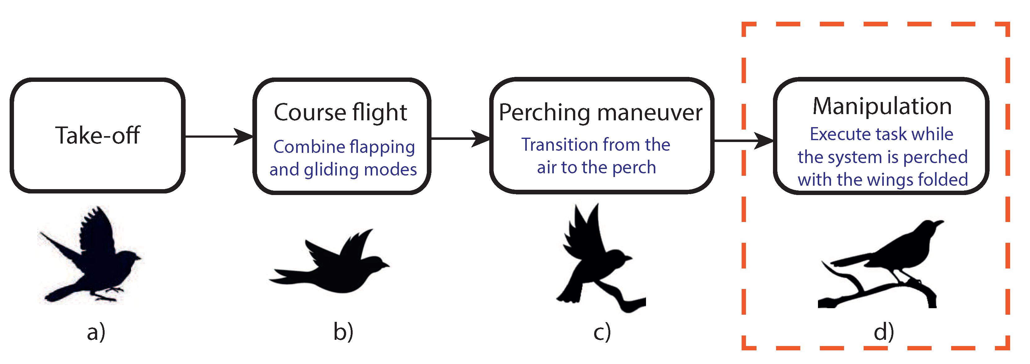
Figure 1 shows the main phases of flapping wing aerial robots carrying out a mission. Our current GRIFFIN European project covers all these phases, for example, previous results have been recently published about the control of perching in [10] and the development of a bio-inspired claw for grasping and perching in [11]. The limited payload capacity of the flapping-wing platforms motivated the design of a small-scale compliant dual arm [12] whose weight is one order of magnitude lower compared to the arms typically integrated in multirotor platforms. Later, we introduced the concept of winged aerial manipulation robot [4] with the aim to reduce the total weight, using the robotic arms with a double functionality, for manipulating and as flapping wings. Each phase is being investigated separately due to the novelty of aerial robots with flapping wings. This work focuses on the development of a first prototype of a lightweight manipulator to be used as ornithopter limbs and explore its control possibilities (Phase (d) of 
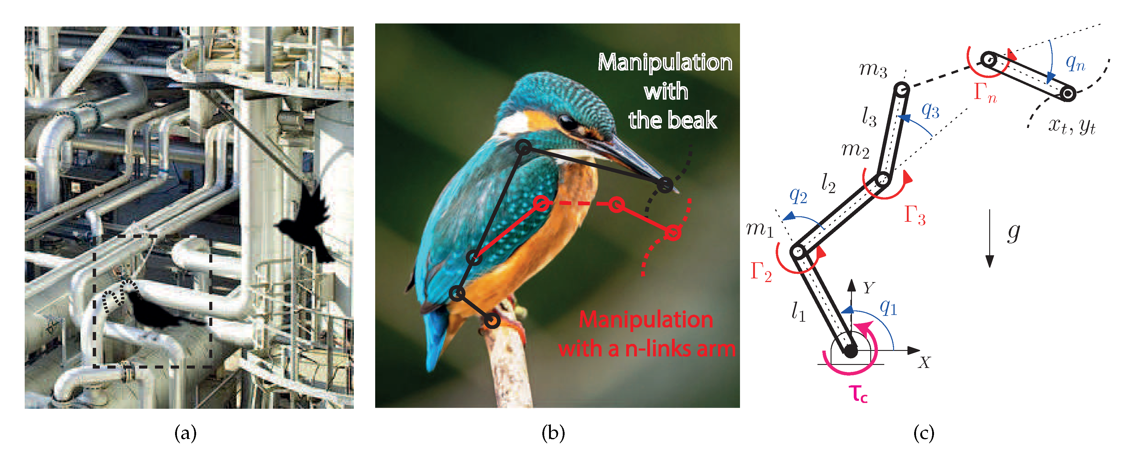
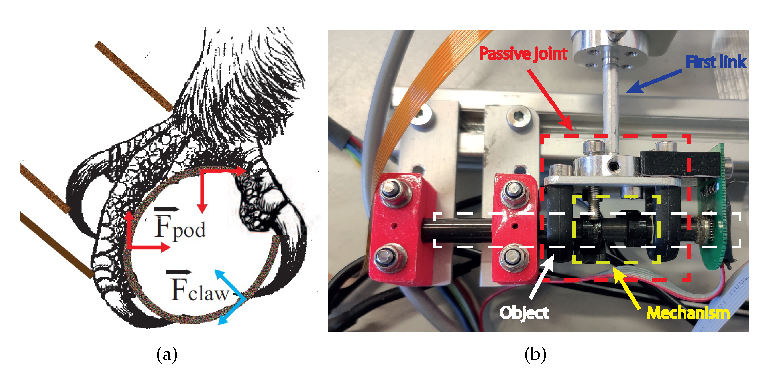
Figure 1). The objective is to maintain the equilibrium while the system performs some tasks such as contact inspection in sites inaccessible by conventional means such as oil and gas refineries (see Figure 2a). We consider the case of the robot with the body perched and the wings folded, which implies that the aerodynamic effects of the body vibration induced by the wing flapping do not need to be considered. To do that, it is very important to understand how birds maintain the equilibrium. Unlike standard manipulators, the most important requirement is being lightweight, which limits the frame size and torques and hence the use of micro motors. Under these hard constraints, their control becomes very challenging with two main objectives: to balance the body while the system is perched; to follow trajectories with the end effector of the manipulator in order to perform some kind of task.
Moreover, in this work we focus on an underactuated manipulator prototype, i.e., fewer control inputs than degrees of freedom, because it is not actuated at the point of perching (passive joint). Underactuated mechanical systems are well known and their inherent difficulty of a lack of actuation have made them a challenge for the control community. In particular, the current system has a similar behavior to the acrobot [13]. This system is a two-link underactuated robot that mimics the human acrobat who hangs from a bar and tries to balance his/her body. The control of n-link underactuated robot with passive first joint has been studied recently as in e.g., [14,15,16,17]. Moreover, very few researchers have addressed the control of n-link underactuated robot with the influence of a static friction on the unactuated passive joint [18,19] due to the great difficulty of controlling these systems with a static friction in the passive joint. Two main control objectives have been studied with these kind of systems: (1) the stabilization of the system around an equilibrium point and (2) the swing-up problem.
Unlike these standard underactuated manipulators, in this work we demonstrate that the use of a grabbing mechanism at its base imitating a bird’s claw allows us to simplify the controller design by combining the friction exerted by the mechanism and an adequate control of the system posture, and, more importantly, it allows us to follow trajectories with the end effector of the manipulator while balancing the system, which will be necessary for performing manipulation tasks such as the contact inspection following trajectories with an ultrasonic sensor mounted in the end-effector. In this work, a simple mechanism was assembled to exert an equivalent friction torque at the base, which was used to verify the effectiveness of the proposed control methodology. In parallel, a bio-inspired claw was developed in our lab for the final prototype.
The main contributions of this work are: the mechanical design of a manipulator imitating the skeleton of a bird with lightweight micro motors and, a novel bio-inspired control methodology that accounts for the static friction in the first passive joint (claw) for a precise control of the posture of the system. Moreover, this work addresses, for the first time, the control of an n-link manipulator with underactuation and static friction at its first passive joint in order to follow a path with the end-effector (beak).
Both the design of the manipulator and the control approach are bio-inspired and based on the behaviors of bird species. Our results show that this framework opens the possibility to perform manipulation, such as performing contact inspection when the system is perched, and the early prototype developed successfully mimics the anatomy of birds and allows us to verify the efficiency of the proposed control strategy and, therefore, it is a good starting point for future developments. Finally, Table 1 summarizes the main differences of the previously mentioned works and ours, where we show that our work is the only work that has proposed a methodology to perform trajectory tracking with the end-effector of an n-link underactuated robot with the first passive joint.
The article is organized as follows. Section 2 presents the description of the system and the actual manipulator prototype is described. Section 3 describes the mathematical modeling of the system. Section 4 describes the proposed control strategy. The experimental results are reported in Section 5. Finally, the conclusions are given in Section 6.
Notation: For any vector r R n , r kn = [ r k , r k + 1 , , r n ] T and r stands for its Jacobian.

2. Prototype of Lightweight Manipulator for Ornithopters

2.1. Description and Control System Requirements

Birds have no arm-like limbs except for their wings, but instead use their beaks as an external anatomical structure for eating, killing prey or manipulating objects while they have their wings folded. The objective of this work is to open the possibility of using ornithopters with manipulation capabilities while they are perched with wings folded. Imitating nature, an artificial beak could be used in ornithopters in order to do manipulation tasks (black line in Figure 2b). However, another approach would be to add an artificial arm composed of a higher number of links and actuated joints in order to improve the workspace of the system (red line in Figure 2b). The difference is that in the black-line approach, the system is composed of four links and joints, whereas in the red-line one, the system is composed of n-links and joints, because a possible extension adding extra links (degrees of freedom) can be considered. Therefore, the system is composed of a leg actuated in the knee joint, a body actuated in the hip joint and an actuated arm/beak. In Figure 2c we depict a schematic drawing of the system performing some kind of manipulation and considering the two aforementioned approaches. In this paper, we consider the first prototype in a two dimensional space, which is enough to perform many inspections tasks. A 3D system will be made in the future with a pair of equal manipulators.
Regardless of the approach of manipulating with a beak or an artificial arm, the system is represented with n links of length l i , i = 1 , , n , and masses concentrated at their tips m i (the motors are attached at the tips except for the link n). In both approaches, link 1 is passive at its base where it can rotate freely, and the other joints are all actuated by torques, namely Γ i , i = 2 , , n , provided by motors. The system is not actuated at its base but it needs a mechanism to emulate the action of a claw at the place of perching, τ c . At a first approximation to the problem, a passive joint is considered. Figure 2c shows a sketch of the system where q i are the angles of the joints with respect to their local reference frames while { x t , y t } are the end-effector Cartesian coordinates acting like a beak. Two control subsystems can be identified: the first two joints q 1 , q 2 in charge of maintaining the posture (similar to an acrobot); the remaining fully-actuated links in charge of following a specified trajectory (see Figure 2b).

2.2. Description of the Lightweight Manipulator Prototype

Underactuated mechanical systems with a passive joint at its base, like the one of the discussion above, are very unstable and very difficult to control. For that reason, the motors have very strict requirements, specifically, they need to be: (1) very precise; (2) high torque; (3) high speed, in order to compensate for the inaccuracies of the system. Additionally, if they have to be mounted in ornithopters, a fourth requirement of the size and the weight is necessary. Very lightweight and precise motors that provide high torque can be obtained using high-ratio reduction gears at the price of reducing the speed of the system. On the contrary, motors that moves at high speeds providing high torques have to be very powerful, thus increasing their weight and the weight of the required batteries. Therefore, all of these requirements can not be achieved simultaneously. Thus, the prototype developed can be seen in Figure 3, representing the links, joints and electronic components (see the similarity with Figure 2). The ankle joint is passive, it can rotate freely around an aluminum shaft, emulating the claw of the bird grabbing a branch. The knee and hip joints are actuated by two customized servo actuators shown in Figure 4.
The lightweight design approach considered in this work is mainly associated to the choice of the actuators and the features of the frame structure that supports the manipulator. Since the control performance of the smart servo actuators like Dynamixel or Herkulex typically employed in aerial manipulation is constrained by the serial communications (with update rates below 100 Hz) and the embedded position controller, it is necessary to develop customized actuators that provide sufficient torque/speed with higher control rates while reducing their weight. In order to achieve the adequate balance between weight and control performance, two groups of actuators are considered: medium weight Maxon–Harmonic Drive (knee joint), and low weight Pololu micro servos (hip joint). Polylactic acid (PLA) and polymer parts were used to assembly the motor with the gearbox and the support frames, whereas the frame structure of the manipulator is manufactured with flat and L-shaped aluminum frames and thin tubes. In this sense, it is desirable that the structure is lightweight while providing a certain rigidity and robustness, also facilitating the assembly of the manipulator. Note that the weight can be optimized replacing the aluminum parts by carbon fiber, or using nylon screws instead of steel ones, although this is out of the scope of this paper. Table 2 indicates the mass density of these materials to evidence the relative weight of each component.
The knee actuator (70 g weight) consist of a Harmonic Drive CSF-5 gearhead combined with a Maxon EC20 flat motor, assembled through a 3D printed plastic frame. This actuator provides zero backlash and high torque performance to satisfy the control requirements. The Maxon motor is controlled in torque by an ESCON 36/3 controller interfaced in PWM mode at 500 Hz. This motor set works with a power supply of 12 volts. The hip actuator is a customized micro servo (25 g weight) based on the Pololu micro metal gear motors and it works with a power supply of 7.5 volts. The device embeds the DRV8833 motor driver and a STM32F100 microcontroller in a small PCB attached to the case, allowing for a low level control of the motor at 500 Hz. Both the ankle and knee joints integrate two magnetic encoders AMS5047 to measure accurately the rotation angle at 500 Hz rate, using a STM32Nucleo microcontroller board to generate a data packet that is sent through the USART interface at 230,400 bps to the computer where the control program in C/C++, and is executed using Ubuntu 16.04 OS.
The rotation angle of the hip joint is measured with a Murata potentiometer SV01 integrated in the micro servo and connected through another serial interface. The frame structure was manufactured in aluminum, using Pololu universal mounting hubs to connect the links, and two igus ESTM-06-SL polymer bearings to support the rotation of the passive joint at the base of the manipulator. The hard/soft-ware architecture of the system is represented in Figure 5. The developed prototype employs two different actuators at the knee and hip joints due to the different design requirements associated to each of them. Since the dynamic equilibrium of the ankle joint (passive) is achieved through the knee actuator, it is desirable that this provides a better performance in terms of torque, zero backlash and mechanical robustness at the expense of increasing the weight, whereas in the hip joint, it was preferred to reduce the weight and inertia of the upper part of body, allowing a certain degree of clearance in the micro servo. Although Harmonic Drive provides a smaller gearbox model (CSF-3B, 11 g weight, 0.1 Nm torque), the total weight of the actuator, including the brushless motor, assembly frame and electronics, which would be similar to the CSF-5 model.
Table 3 shows the physical parameters of the system model: the concentrated masses at the tip of the links m i and the masses m b i and the length l i of the links, respectively. Notice that, in third-joint tip an equivalent mass is added.

2.3. Claw Grasping Prototype at the Passive Joint

In nature, flapping wing animals land on a wide range of different surfaces and perform some tasks, by combining the grasping force from their claws and the balance of the body. Some previous works have studied the morphology of bird feet and claw shape in relation to body size and lifestyle [20,21]. Other works have studied the foot–surface interaction when the birds perch [22], this explains how some animals may grasp complex surfaces reliably. The grasping force planar model proposed in [22] does not take into account lateral forces out of the plane, and hence only being valid once the bird’s claws are fully wrapped. In summary, the grasping force: (1) it is composed of the friction generated by toe pad and the strength of the force exerted by the claw; (2) it can be modeled as a static friction; (3) it depends on the contact surfaces at perch (surface and claw) as well as their orientation, texture, geometry, etc. In Figure 6a the force diagram of the claw of a flapping wing animal perched in a cylindrical surface is depicted.
In this way, a mechanism to emulate a claw exerting an equivalent friction torque at the passive joint was designed and assembled to the manipulator prototype (see Figure 6b). A set of screws were placed perpendicular to the object where the system was attached. The bottom part of the screws have a plastic washer in order to increment the friction between the mechanism and the object. The mechanism is always fixed at its base and the position of the screws can be manually modified in order to vary the friction between the mechanism and the object by changing the contact surface between the screws and the bar. This mechanism was used as a benchmark to assess the requirements in the development of the control and the design of a bio-inspired manipulator, where we also have some recent developments with SMA technologies [11], even though this technology is not yet mature enough to be used in control.
To further test the performance of our control strategy, the maximum value of the friction torque, τ c , l , exerted by the mechanism has been characterized as a function of the position of the screws. The results are collected in Table 4, where Δ x ( mm ) is the depth of the screw in contact with the plastic washer. The deeper length in contact with the plastic washer, the higher friction torque exerted.

3. Mathematical Modeling of the System

To simplify, let us start with the derivation of the dynamics of an n-link under actuated manipulator. Thus, let q = [ q 1 , q 2 , , q n ] T R n denote the vector of generalized coordinates for the joint angles, and U = [ Γ 1 , Γ 2 , , Γ n ] T R n the vector of inputs and generalized torques. Hence the Lagrange dynamic equations read
M ( q ) q ¨ + C ( q , q ˙ ) q ˙ + G ( q ) = U ,
where M ( q ) R n × n is a symmetric positive definite inertia matrix; C ( q , q ˙ ) R n × n is the gyroscopic and Coriolis matrix; G ( q ) R n is the vector of gravitational terms. To complete the dynamics we add the nonlinear external torque exerted by the claw at the base, i.e., q 1 . To this end, let us split the dynamics (1) into passive (claw) and active (control) subsystems as follows
M 1 M c M c T M 2 n q ¨ 1 q ¨ 2 n + C 1 C c 1 C c 2 C 2 n q ˙ 1 q ˙ 2 n + g 1 g 2 n = τ c τ
where we have defined q 2 n : = [ q 2 , q 3 , , q n ] T , g 2 n in a similar way, τ : = [ Γ 2 , Γ 3 , , Γ n ] T and Γ 1 : = τ c stands for the external friction torque modeling the claw of a bird (see Figure 2c). Now, from the first equation of (2), let us denote the resulting dynamic torque at the base q 1 whenever q ˙ 1 = 0 as τ 1 : = M c q ¨ 2 n + C c 1 q ˙ 2 n + g 1 . Thus, as described in Section 2.3, the grasping torque provided by the claw, namely τ c R , can be modeled as a static friction—so called stiction—as follows
τ c : = τ c , l · s g n [ q ˙ 1 ] i f q ˙ 1 0 ; τ c , l · s g n [ τ 1 ] i f q ˙ 1 = 0 a n d | τ 1 | > τ c , l ; τ 1 i f q ˙ 1 = 0 a n d | τ 1 | < τ c , l ;
where τ c , l is its maximum value of the grasping torque. Notice that, if τ 1 does not surpass τ c , l , the angular coordinate of the first joint remains unchanged, i.e., q ˙ 1 ( t ) 0 , t 0 . More information about friction models see [23].
Remark 1.
Notice that the grasping torque of the claw τ c in (3) strongly modifies the dynamics when compared with a frictionless underactuated manipulator with a passive joint at its base, as it can be seen e.g., [15,16,24]. The static friction, so-called stiction, induces a highly nonlinear behavior around q ˙ 1 = 0 , q 1 = q 10 constant.
Finally, the Cartesian position ( x t , y t ) of the end effector and joint coordinates are related through the geometric constraint, with respect to the reference frame ( X , Y ) defined in Figure 2c, and it reads
x t y t = i = 1 n l i cos i = 1 n q i i = 1 n l i sin i = 1 n q i .

4. Nonlinear Control Design

In this section we propose a new control methodology for the manipulation of ornithopters while they are perched. Roughly speaking, it aims to track a desired trajectory for the end effector (beak) of the underactuated manipulator while the passive joint (claw) maintains the equilibrium. The proposed control methodology is stated for an n-link manipulator with the first joint passive by means of a grabbing mechanism. For experimental validation the prototype had n = 3 as described in Section 2.2.
The proposed control strategy relies on the fact that the grasping torque the claws can exert is limited and unknown a priori because it depends on both contact surfaces. Furthermore, since the pose of the whole system depends on the balance of torques at the passive joint, the control strategy accounts for both the limited grasping torque and the system posture. Thus, the condition to maintain the passive joint at equilibrium can be obtained directly from (2) and (3) as | τ 1 | τ c , l and q ˙ 1 = 0 . To simplify the control problem, we know that at slow speed the inertial and centripetal terms in (2) are very small in comparison with gravity ones, and the previous equilibrium condition is well approximated by
| τ 1 | | g 1 | τ c , l , with g 1 = i = 1 n β i cos k = 1 i q k ,
where the function g 1 accounts for the resultant torque at the passive joint due to gravity and β i constant parameters. Even with that simplification, the control of this robot is challenging because the grasping torque is unknown and its accurate estimation is not available for feedback.
The controller must, therefore, adequately perform for different values of grasping torque, which means to control the position of the system while the base is at equilibrium. To this end, we propose to minimize the resultant torque at the passive joint, for any initial angle q 1 ( 0 ) = q 10 , through the first active joint q 2 and achieve a nearly perfect tracking in the position of the remaining active joints q 3 n . This can be mathematically formulated as follows.
Control problem statement: Consider the input ( τ ) to output ( y ) nonlinear control system given by
M 2 n ( q ) q ¨ 2 n + C 2 n ( q , q ˙ 2 n ) q ˙ 2 n + g 2 n ( q ) = τ ,
y = [ y 1 , y 2 ] T : = [ g 1 ( q 10 , q 2 n ) , q 3 n ] T R × R n 2 ,
with q ˙ 1 ( t ) 0 , t 0 . The control objective is to guarantee the asymptotic output tracking of a smooth bounded desired output y * ( t ) with bounded y ˙ * ( t ) and y ¨ * ( t ) for t 0 .
Remark 2.
Notice that, in (7) even though q 2 is measured, it is not defined as a direct output. However, its desired behavior is indirectly defined through the output y 1 . Setting y 1 * = 0 minimizes the gravitational forces at the passive link and eventually maintains this joint q 1 at equilibrium q 1 = q 10 by enforcing | g 1 | τ c , l of (5).
To control the system (6) and (7) we used feedback linearization. The gist of this control technique is to cancel out all the nonlinearities so that the output dynamics become linear. In essence it transforms the original system into an equivalent linear form by change of coordinates and feedback. Thus, since the whole state X = [ q , q ˙ ] is measurable, the system can be linearized by means of a fictitious control input v .
To facilitate the understanding we split the controller design in an inner and outer loop. The inner loop is in charge of linearizing the actuated dynamics. Thus, from (6) we have
M 2 n q ¨ 2 n + C 2 n q ˙ 2 n + g 2 n v = τ = : M 2 n · v + v ,
with v the fictitious input, resulting in the following
q ¨ 2 n = v .
On the other hand, the outer loop is in charge of calculating the fictitious input v as a function of the outputs y . For, the output dynamics of y 1 R become
y ˙ 1 = p ( q ) q ˙ , y ¨ 1 = q ˙ T · p · q ˙ + p 1 q ¨ 1 f ( · ) + p 2 q ¨ 2 + p 3 n T q ¨ 3 n
where p ( q ) = [ p 1 , p 2 , , p n ] T and whose components read
p i = j = i n β j sin k = 1 j q k .
Therefore, together with (8) the output dynamics become
y ¨ 1 y ¨ 2 y ¨ = f ( · ) 0 F n 1 + p 2 p 3 n T 0 I n 2 P n 1 v
where I n 2 is the identity matrix. These dynamics represent an explicit relationship between y and v . By defining v : = P n 1 1 ( u F n 1 ) , p 2 0 , the linear output dynamics become
y ¨ = u .
Finally, we enforce the closed-loop Hurwitz, λ 1 , λ 2 > 0 , with
u : = y ¨ * + λ 2 y ˜ ˙ + λ 1 y ˜
where y ˜ : = y * y . To sump up, the controller designed reads
τ = M 2 n P n 1 1 ( y ¨ * + λ 2 y ˜ ˙ + λ 1 y ˜ F n 1 ) + C 2 n q ˙ 2 n + g 2 n .
The controller (
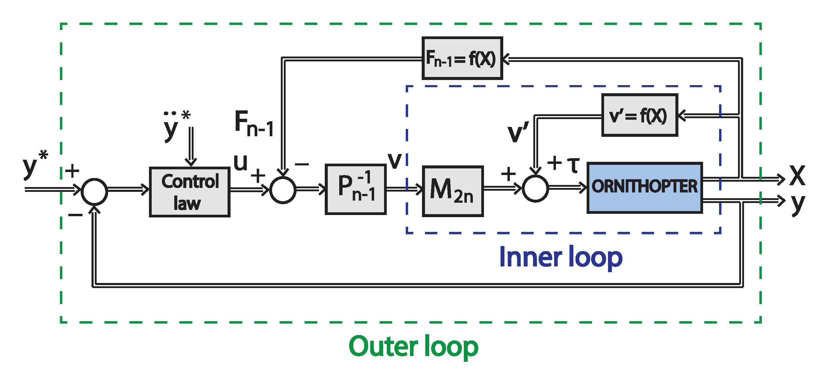
12) cancels out all the nonlinearities of the system and assures that the tracking error of the outputs of the closed-loop system converges to zero exponentially while keeping the whole state bounded. In Figure 7, we depict the block diagram of the control architecture.
The stability result is summarized in the proposition below.
Proposition 1.
Consider the input–output nonlinear system (6) and (7) and a desired output trajectory y * ( t ) , t 0 , such that p 2 ( q ) defined through (9) is away from zero. Then, the smooth static-state feedback (12), with λ 1 , λ 2 > 0 , ensures that the origin of the output error is locally exponentially stable in Ω 0 Ω , for any initial condition inside the set
Ω : = { ( q ( 0 ) , q ˙ 2 n ( 0 ) , q ¨ 2 n ( 0 ) ) R 3 n : q ˙ 1 ( 0 ) = 0 , | τ 1 | τ c , l } .
Proof. 
First, any initial condition in Ω implies that the passive link is at equilibrium at q 1 ( 0 ) q 10 . Secondly, the condition p 2 0 guarantees the existence of the static-state feedback (12) that forces an equivalent dynamics between q 2 n and y , from (8) to (10). Thus, defining Y ˜ : = [ y ˜ T , y ˜ ˙ T ] T , the closed-loop output linear dynamics become Y ˜ ˙ = A Y ˜ with
A : = 0 n 1 I n 1 λ 1 I n 1 λ 2 I n 1 ,
which is Hurwitz for any λ 1 , λ 2 > 0 . Thus, the latter guarantees exponential convergence and hence the closed-loop output error can be confined in a ball Ω 0 Ω such that the condition | τ 1 | τ c , l holds for t 0 , concluding the proof.  □

5. Experimental Results

Experiments were carried out with the prototype described in the Section 2.2 in order to demonstrate the efficiency and robustness of the proposed technique. It is important to highlight that the proposed control strategy is valid for a system with n links, n > 2 
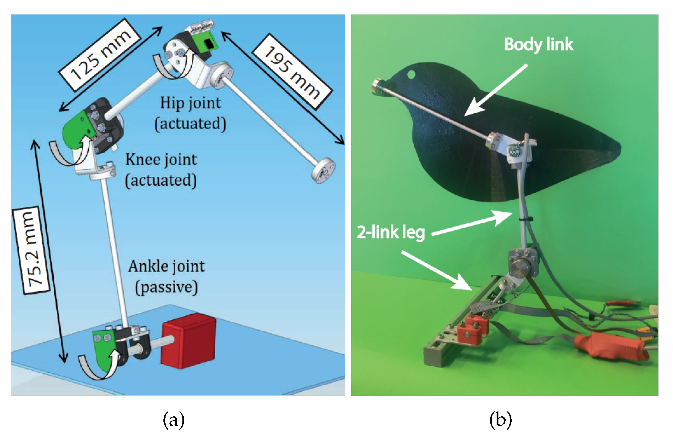
. Our prototype has three links and two actuators, with one passive joint, which is the ankle joint, and two active joints actuated by micro motors, which are the knee and hip joints (see Figure 3). The parameters of the mathematical model for our prototype are in Table 3, where the components of the matrices can be found in [24]. Notice that the masses m i are much higher than the m b i . The controller design parameters of (12) were specified to place the poles of the system in the real axis and sufficiently far from the imaginary axis with λ 1 = 784 and λ 2 = 56 ( p i = 28 ). For the experiment, the passive joint angle was fixed to q 1 = 65 . The third joint of the prototype acts like the beak (see Figure 3), which has to follow a desired path with measurements taken at different target points. A grasping torque with the value τ c , l = 0.015 Nm (position of the screw Δx = 0.5 mm from Table 4) was exerted at the base. A large trajectory was designed to cover a wide range of the workspace, assuring that p 2 0 , which means that the matrix P n 1 1 is full rank and the control law (12) can be implemented. The desired trajectory of the end effector of the manipulator is defined by q 10 = 65 and, the desired trajectory q ¯ 2 imposed by the control objective { q ¯ 2 R : y 1 * = g 1 ( q 10 , q ¯ 2 , y 2 * ) = 0 } , with y 2 * = q 3 * . The desired trajectory, q 3 * is defined by Bezier curves, which are smooth curves that can be differentiated indefinitely where the position and time of the trajectory is defined in Table 5.
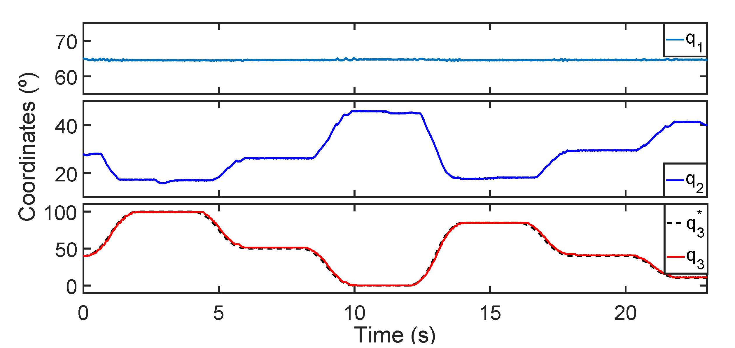
Figure 8 shows the angular coordinates of the passive joint, of the second joint (active) to maintain the equilibrium at the passive joint and of the third joint (active) together with its reference. Notice that the controller achieves an almost perfect tracking positioning in the third joint while maintaining the equilibrium at the first one. In essence, the controller balances the resultant torque at the second joint.
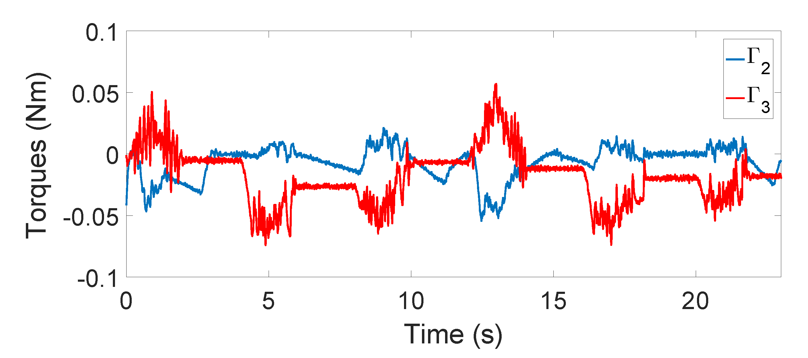
In Figure 9 we show the torque of the motors during the movement. The saturation torque of the motors is 0.5 Nm, and therefore, they are far from saturating along the experiment, which is essential in this bio-inspired application.
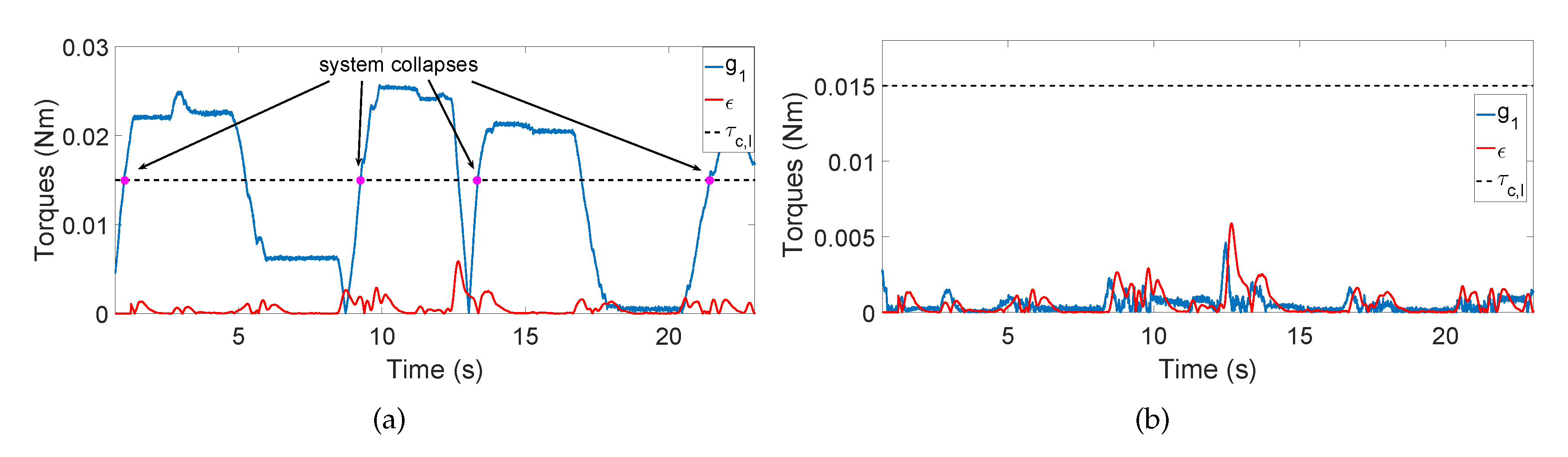
Recall that the resultant torque at the passive joint was defined as τ 1 : = M c q ¨ 2 n + C c 1 q ˙ 2 n + g 1 . Let us define the inertial and centripetal terms in this joint as ϵ : = M c q ¨ 2 n + C c 1 q ˙ 2 n , so that τ 1 = ϵ + g 1 . Thus, in Figure 10a we show a new experiment following the trajectory q 3 * defined in Table 5 but with the second joint locked instead of using the proposed controller. The points where the passive joint would have collapsed and the system would have fallen down if the grasping torque was not increased are depicted with circles. This experiment demonstrates that: (1) inertial and centripetal terms are very small in comparison with the gravity ones, and hence corroborating our approximation (5) of | ϵ | < < | g 1 | implying that | τ 1 | | g 1 | ; (2) without control we have to increase the grasping torque to be able of maintaining the equilibrium at the passive joint (at least 0.03 Nm which correspond to Δ x = 1 mm). On the other hand, in Figure 10b, we show the performance of the proposed controller along the same trajectory of the initial experiment. It is clear that the controller is able to minimize the gravity term | g 1 | up to the same size of | ϵ | , and therefore, guaranteeing | τ 1 | τ c , l while the posture is maintained.
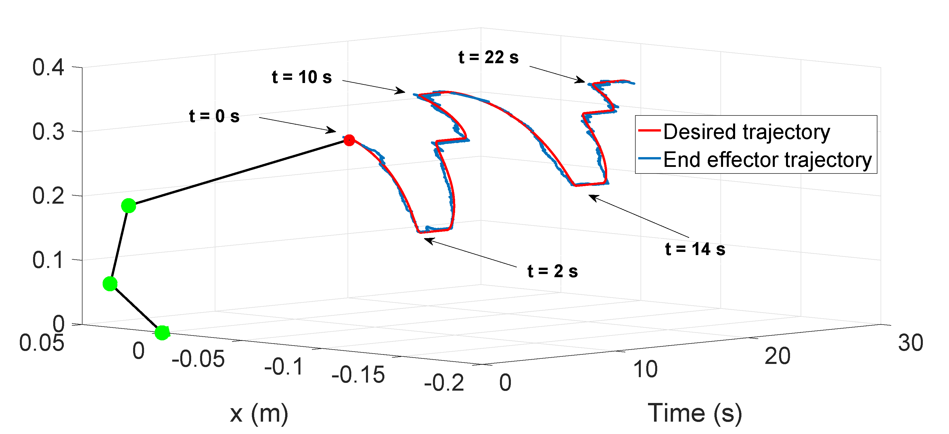
Finally, in Figure 11 we show the complete movement of the system in Cartesian coordinates along the time (blue line) using the proposed controller.
The sketch of the manipulator at t = 0 is included to have a better idea of the posture of the system during the movement. The desired trajectory that the end effector (beak) has to follow is also depicted (red line). In Figure 12 the different desired positions of Table 5 was enumerated in order to show the positions of the entire structures along the experiment. We can see that a good trajectory tracking with the end effector is achieved while the system maintains the equilibrium. The maximum error is around 8 mm during the transitions, however, when the system finished these transitions, the error is less than 2 mm. These errors are negligible in comparison with the size of the manipulator (length of the manipulator is around 400 mm). In summary, these experiments validate the proposed controller for this bio-inspired prototype with small-torque motors opening the possibility to perform trajectory tracking with the end effector of underactuated manipulators which has promising applications, such as performing contact inspection.

6. Conclusions

In this study, we investigated the control possibilities of adding manipulation capabilities to ornithopters. Manipulation with ornithopters is of the utmost interest in several applications due to their promising advantages respect to multirotor platforms. The methodology proposed in this work provides a simple alternative design framework to control these systems. Although our prototype has three links, the proposed methodology is generalizable for manipulators with more links. The control law is designed to minimize the position deviation of the end effector of the manipulator from the nominal path. The control problem is split into two: the leg subsystem (underactuated), composed of the two first links to maintain the equilibrium and the remaining links of the system, which are fully actuated to follow a desired trajectory with the end effector of the manipulator.
The control scheme is based on input–output feedback linearization proposing a novel bio-inspired output. Another contribution is the first 3 D O F prototype of lightweight manipulator to be mounted in ornithopters. The manipulator imitates the birds skeleton, which has two-link legs and the body link. This prototype has a lot to move forward, however, it allows us to verify the efficiency of the developed control methodology. Successful experimental results demonstrate the validity of the approach.
Regarding the actuation system, more complex control systems could have been devised with different actuators. However, the weight of the motors would have increased, violating the aforementioned critical requirement for aerial robots, namely its minimum weight and energy consumption.
Currently, work is underway to design an ultra-lightweight version of the manipulator (including a bio-inspired claw) and the necessary mechanisms to mount it in a real ornithopter.

Author Contributions

Conceptualization, D.F.-T., J.Á.A., A.S. and A.O.; methodology, D.F.-T. and J.Á.A.; software, D.F.-T. and A.S.; validation, D.F.-T.; project administration, A.O.; writing—original draft preparation, D.F.-T. and J.Á.A.; writing—review and editing D.F.-T., J.Á.A., A.S. and A.O. All authors have read and agreed to the published version of the manuscript.

Funding

This work has been funded by the European Research Council Advanced Grant GRIFFIN (General compliant aerial Robotic manipulation system Integrating Fixed and Flapping wings to INcrease range and safety), Action 788247.

Conflicts of Interest

The authors declare no conflict of interest. The founding sponsors had no role in the design of the study; in the collection, analyses or interpretation of data; in the writing of the manuscript and in the decision to publish the results.

References

  1. Ollero, A.; Siciliano, B. Aerial Robotic Manipulation; Springer: Berlin/Heidelberg, Germany, 2019. [Google Scholar]
  2. Ollero, A.; Heredia, G.; Franchi, A.; Antonelli, G.; Kondak, K.; Sanfeliu, A.; Viguria, A.; Martinez-de Dios, J.R.; Pierri, F.; Cortés, J.; et al. The AEROARMS project: Aerial robots with advanced manipulation capabilities for inspection and maintenance. IEEE Robot. Autom. Mag. 2018, 25, 12–23. [Google Scholar] [CrossRef] [Green Version]
  3. H2020-EU ERC Advanced Grant 788247. General Compliant Aerial Robotic Manipulation System Integrating Fixed and Flapping Wings to Increase Range and Safety. 2018. Available online: https://cordis.europa.eu/project/id/788247 (accessed on 4 August 2020).
  4. Suarez, A.; Grau, P.; Heredia, G.; Ollero, A. Winged Aerial Manipulation Robot with Dual Arm and Tail. Appl. Sci. 2020, 10, 4783. [Google Scholar] [CrossRef]
  5. Woods, M.; Henderson, J.; Lock, G. Energy requirements for the flight of micro air vehicles. Aeronaut. J. 2001, 105, 135–149. [Google Scholar] [CrossRef]
  6. Ellington, C.P. The novel aerodynamics of insect flight: Applications to micro-air vehicles. J. Exp. Biol. 1999, 202, 3439–3448. [Google Scholar] [PubMed]
  7. Platzer, M.F.; Jones, K.D.; Young, J.; Lai, J.S. Flapping wing aerodynamics: Progress and challenges. AIAA J. 2008, 46, 2136–2149. [Google Scholar] [CrossRef]
  8. Hang, K.; Lyu, X.; Song, H.; Stork, J.A.; Dollar, A.M.; Kragic, D.; Zhang, F. Perching and resting—A paradigm for UAV maneuvering with modularized landing gears. Sci. Robot. 2019, 4, eaau6637. [Google Scholar] [CrossRef]
  9. Paranjape, A.A.; Chung, S.J.; Kim, J. Novel dihedral-based control of flapping-wing aircraft with application to perching. IEEE Trans. Robot. 2013, 29, 1071–1084. [Google Scholar] [CrossRef] [Green Version]
  10. Maldonado, F.J.; Acosta, J.A.; Tormo Barbero, J.; Grau, P.; Guzman, M.M.; Ollero, A. Adaptive Nonlinear Control For Perching of a Bioinspired Ornithopter. In Proceedings of the 2020 IEEE/RSJ International Conference on Intelligent Robots and Systems (IROS), Las Vegas, NV, USA, 25–29 November 2020. [Google Scholar]
  11. Gomez-Tamm, A.E.; Perez-Sanchez, V.; Arrue, B.C.; Ollero, A. SMA Actuated Low-Weight Bio-Inspired Claws for Grasping and Perching Using Flapping Wing Aerial Systems. In Proceedings of the 2020 IEEE/RSJ International Conference on Intelligent Robots and Systems (IROS), Las Vegas, NV, USA, 25–29 November 2020. [Google Scholar]
  12. Suarez, A.; Perez, M.; Heredia, G.; Ollero, A. Small-Scale Compliant Dual Arm with Tail for Winged Aerial Robots. In Proceedings of the 2019 IEEE/RSJ International Conference on Intelligent Robots and Systems (IROS), Macau, China, 3–8 November 2019; pp. 208–214. [Google Scholar]
  13. Spong, M.W. The swing up control problem for the acrobot. IEEE Control Syst. Mag. 1995, 15, 49–55. [Google Scholar]
  14. Xin, X.; She, J.H.; Yamasaki, T.; Liu, Y. Swing-up control based on virtual composite links for n-link underactuated robot with passive first joint. Automatica 2009, 45, 1986–1994. [Google Scholar] [CrossRef]
  15. Lai, X.Z.; Pan, C.Z.; Wu, M.; Yang, S.X. Unified control of n-link underactuated manipulator with single passive joint: A reduced order approach. Mech. Mach. Theory 2012, 56, 170–185. [Google Scholar] [CrossRef]
  16. Zhang, A.; Qiu, J.; Yang, C.; He, H. Stabilization of underactuated four-link gymnast robot using torque-coupled method. Int. J. Non-Linear Mech. 2015, 77, 299–306. [Google Scholar] [CrossRef]
  17. Lai, X.; Wang, Y.; Wu, M.; Cao, W. Stable control strategy for planar three-link underactuated mechanical system. IEEE/ASME Trans. Mechatron. 2016, 21, 1345–1356. [Google Scholar] [CrossRef]
  18. Yu, K.H.; Shito, Y.; Inooka, H. Position control of an underactuated manipulator using joint friction. Int. J. Non-Linear Mech. 1998, 33, 607–614. [Google Scholar] [CrossRef]
  19. Liu, D.; Yamaura, H. Giant swing motion control of 3-link gymnastic robot with friction around an underactuated joint. J. Syst. Des. Dyn. 2011, 5, 925–936. [Google Scholar] [CrossRef] [Green Version]
  20. Sustaita, D.; Pouydebat, E.; Manzano, A.; Abdala, V.; Hertel, F.; Herrel, A. Getting a grip on tetrapod grasping: Form, function, and evolution. Biol. Rev. 2013, 88, 380–405. [Google Scholar] [CrossRef]
  21. Pike, A.; Maitland, D. Scaling of bird claws. J. Zool. 2004, 262, 73–81. [Google Scholar] [CrossRef]
  22. Roderick, W.R.; Chin, D.D.; Cutkosky, M.R.; Lentink, D. Birds land reliably on complex surfaces by adapting their foot-surface interactions upon contact. eLife 2019, 8, e46415. [Google Scholar] [CrossRef] [PubMed]
  23. Olsson, H.; Åström, K.J.; De Wit, C.C.; Gäfvert, M.; Lischinsky, P. Friction models and friction compensation. Eur. J. Control 1998, 4, 176–195. [Google Scholar] [CrossRef] [Green Version]
  24. Xin, X.; Kaneda, M. Swing-up control for a 3-DOF gymnastic robot with passive first joint: Design and analysis. IEEE Trans. Robot. 2007, 23, 1277–1285. [Google Scholar] [CrossRef]
Figure 1. Phases of flapping wing aerial robots mission: sequence of the most relevant tasks.
Applsci 10 06516 g001
Figure 2. Schematic of the approach: (a) contact inspection in a refinery; (b) bird perched doing manipulation; (c) manipulator sketch.
Applsci 10 06516 g002
Figure 3. Lightweight manipulator prototype: (a) 3D model; (b) experimental prototype.
Applsci 10 06516 g003
Figure 4. Customized servo actuators: (a) knee joint; (b) hip joint.
Applsci 10 06516 g004
Figure 5. Hardware/software architecture.
Applsci 10 06516 g005
Figure 6. Claw grasping prototype: (a) force diagram of a bird claw; (b) grasping mechanism.
Applsci 10 06516 g006
Figure 7. Controller block diagram.
Applsci 10 06516 g007
Figure 8. Angular coordinates q 1 , q 2 and q 3 .
Applsci 10 06516 g008
Figure 9. Torques of the motors.
Applsci 10 06516 g009
Figure 10. Torques at the passive joint: (a) without using the proposed controller; (b) using the proposed controller.
Applsci 10 06516 g010
Figure 11. End effector (beak) Cartesian positions along time during the experiment.
Applsci 10 06516 g011
Figure 12. Configuration of the prototype at different end effector positions (Table 5).
Applsci 10 06516 g012
Table 1. Summary of previous works based on the control of an n-link underactuated manipulators with passive first joint.
Number of LinksFriction on the Passive JointSwing-Up ApproachStabilization around Equilibrium PointTrajectory TrackingExperimental Results
 [13]2
[14]n
[15]n
[16]n
[17]3
[18]n
[19]3
Our work n > 2
Table 2. Mass density of different materials employed in the manipulator prototype.
MaterialPLA, PolymerCarbon fiberAluminumMotors (Pololu–Maxon HD)Steel
Mass Density (g/cm3) 1.4 1.5 2.7 3–6 7.8
ComponentFrame partsFrame partsLinksActuatorsScrews
Table 3. Physical parameters of the manipulator.
i123
m i (kg) 0.07 0.025 0.03
m b i (kg) 0.005 0.005 0.008
l i (m) 0.0752 0.125 0.195
Table 4. Mechanism characteristics.
Δ x ( mm ) 0 0.5 1 1.5 2 2.5
τ c , l ( Nm ) 0 0.015 0.036 0.060 0.081 0.1
Table 5. Trajectory q 3 * .
t (s)02610141822
q 3 * (°)40100500804010

