Review

Trends in the Characterization of the Proximal Humerus in Biomechanical Studies: A Review

by
Angel D. Castro-Franco
,
Ismael Mendoza-Muñoz
*,
Álvaro González-Ángeles
,
Samantha E. Cruz-Sotelo
,
Ana Maria Castañeda
and
Miriam Siqueiros-Hernández
Engineering Faculty, Autonomous University of Baja California (UABC), 21100 Mexicali, Baja California, Mexico
*
Author to whom correspondence should be addressed.
Appl. Sci. 2020, 10(18), 6514; https://doi.org/10.3390/app10186514
Submission received: 11 August 2020 / Revised: 13 September 2020 / Accepted: 16 September 2020 / Published: 18 September 2020
(This article belongs to the Special Issue Artificial Intelligence (AI) and Virtual Reality (VR) in Biomechanics)

Abstract

:
Proximal humerus fractures are becoming more common due to the aging of the population, and more related scientific research is also emerging. Biomechanical studies attempt to optimize treatments, taking into consideration the factors involved, to obtain the best possible treatment scenario. To achieve this, the use of finite element analysis (FEA) is necessary, to experiment with situations that are difficult to replicate, and which are sometimes unethical. Furthermore, low costs and time requirements make FEA the perfect choice for biomechanical studies. Part of the complete process of an FEA involves three-dimensional (3D) bone modeling, mechanical properties assignment, and meshing the bone model to be analyzed. Due to the lack of standardization for bone modeling, properties assignment, and the meshing processes, this article aims to review the most widely used techniques to model the proximal humerus bone, according to its anatomy, for FEA. This study also seeks to understand the knowledge and bias behind mechanical properties assignment for bone, and the similarities/differences in mesh properties used in previous FEA studies of the proximal humerus. The best ways to achieve these processes, according to the evidence, will be analyzed and discussed, seeking to obtain the most accurate results for FEA simulations.

1. Introduction

Fracture of the proximal humerus is becoming one of the most common injuries among the elderly and is related to osteoporosis, which deteriorates the microstructure of the bone and decreases its bone mass [1,2,3,4,5]. Fracture risk will increase with population aging [6,7,8]: the changes that come with the biological aging process make the elderly more susceptible to suffering a fracture, given that falls are the major risk factor for this group, along with osteoporosis [9,10,11,12].
The treatment for this type of fracture is still debatable, due to the fracture/patient factors involved in the treatment decision process, and the high complication rates of surgical treatments. The stability and displacement of the fracture, the bone mineral density, the fracture pattern, and the age and comorbidities of the patient are some of the factors to consider for the proper selection of treatment [3,4,13,14,15]. The potential poor outcomes of surgical treatments include non-union, varus collapse, screw-cut, loss of reduction, avascular necrosis, and the need for reoperation [14,16,17].
Therefore, computational biomechanical studies have become more common, which try to solve and validate the different aspects of fracture treatments and enhance their outcomes through finite element analysis (FEA), providing a fast and low-cost experimentation technique and, most importantly, helping to prevent premature failures through fracture/treatment behavior analysis via three-dimensional (3D) models. An FEA can provide information on realistic bone behavior in specific scenarios through a three-dimensional simulation, as long as the mesh parameters, constraints, and mechanical properties are properly selected, especially for the bone [18,19].
Nevertheless, discrepancies exist between studies due to the lack of standards for the characterization of the bone model, including in proximal humerus studies. Each researcher uses different bone material properties and natures; for instance, there are studies were the orthotropic nature is preferred for the bone [20,21], while others use the isotropic nature [3,5,22,23,24,25,26,27,28], even when anisotropy is the actual nature of bone tissues. The research papers also differ in their modeling technique. Some researchers consider the bone as a solid and “homogeneous” model, without distinguishing between the different bone tissue [25,26], while other studies use a threshold to separate cancellous and cortical bone in order to maintain real bone structure in their model [3,5,20,29,30,31]. What is more, each researcher uses dissimilar meshing parameters for their FEA bone models—crucial parameters for the accuracy of outcomes, which vary from the type of element to the element’s edge length.
Hence, this article aims to review the most used bone characterization techniques for the proximal humerus in FEA biomechanical studies, analyzing the different aspects of the modeling process, from bone geometry simplification to the most used mesh parameters. The strengths and limitations of these FEA characterization techniques will also be reviewed, starting from the most basic knowledge you must possess about the proximal humerus to be able to apply them, and considering how to achieve the best and closest-to-reality results from an FEA through the use of revised techniques.

2. Proximal Humerus Anatomy and Bone Composition
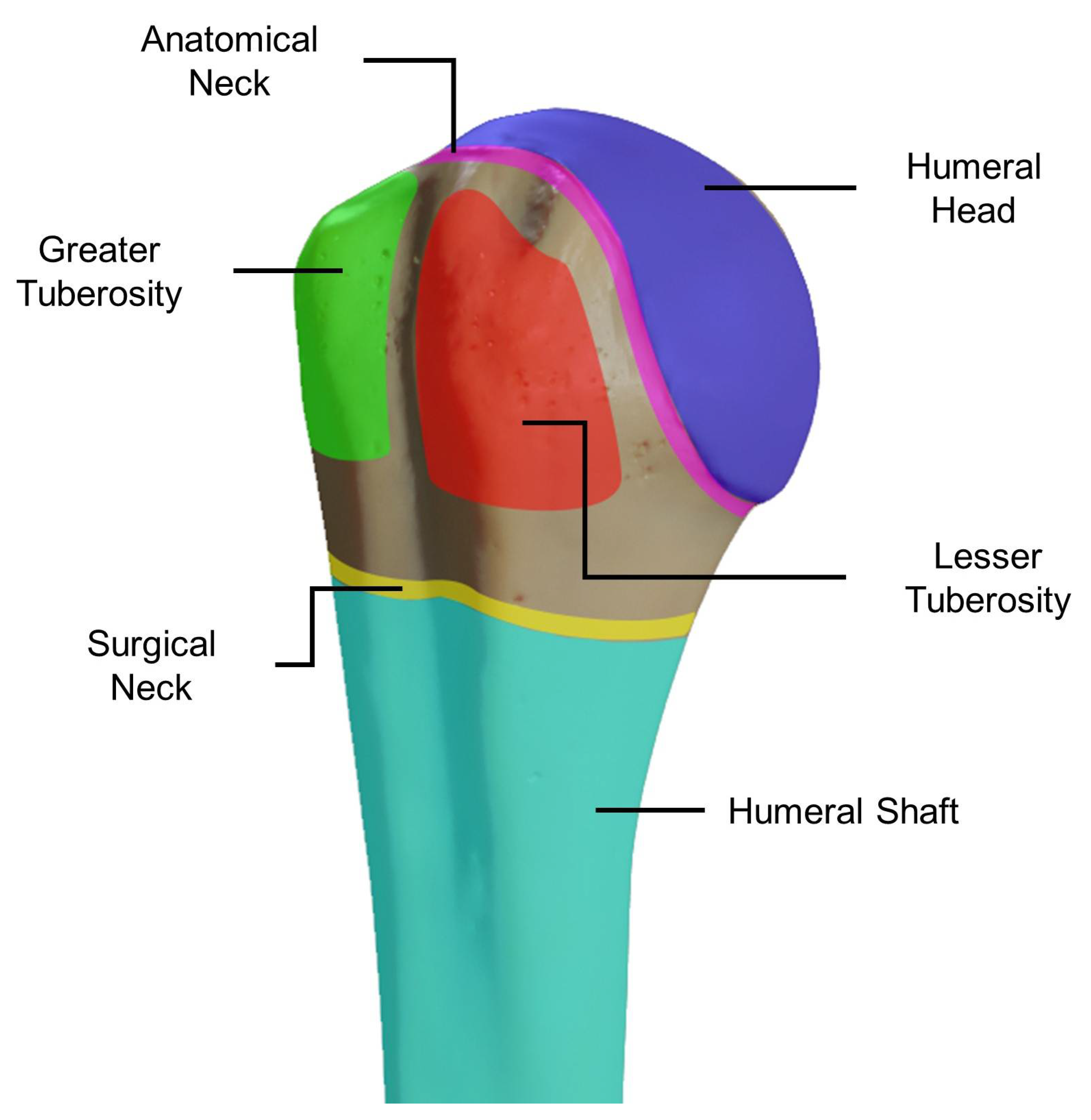
2.1. Bone Shape

Knowledge of the bone anatomy you are working with is a critical part of the modeling process, as the virtual representation must be as close to reality as possible to achieve accurate results. For instance, knowing the composition of the proximal humerus allows one to understand and represent the different types of fracture patterns in an FEA, as well as knowing where the bone should be fixed and where loads should be applied to obtain a good representation of a real-life situation or a particular experimental setting [18,32,33].
The geometry of the proximal humerus can be classified into four main sections: the humeral head (articular surface), greater and lesser tuberosities, and the humeral shaft (Figure 1). The humeral head articulates with the glenoid cavity to form the glenohumeral joint, which is the main joint of the shoulder’s joint system (glenohumeral, acromioclavicular, scapulothoracic, and sternoclavicular joints) and allows shoulder movement. The humeral head has a curvature diameter between 37.1 and 58 mm [34,35]. The tuberosities function to attach the rotator cuff tendons, and the distance from the highest point of the humeral head to the top of the greater tuberosity is usually an average of 8 +/− 3.2 mm [36,37,38].
These sections were used to create the proximal humerus classification systems that we still use today, such as the Neer Classification from 1979 [39], Hertel’s binary description for proximal humerus fractures [40], and the AO Foundation/Orthopedic Trauma Association (AO/OTA) classification, the latter of which is one of the most recent and detailed classifications [41]. Other important sections of the proximal humerus are the anatomical and surgical neck: the anatomical neck is the bony portion where the humeral head and the humeral shaft meet, and the surgical neck is the section just below both tuberosities. The bicipital groove separates the greater tuberosity from the lesser one, and is where the long head of the biceps runs to the shoulder joint [4,36,37].

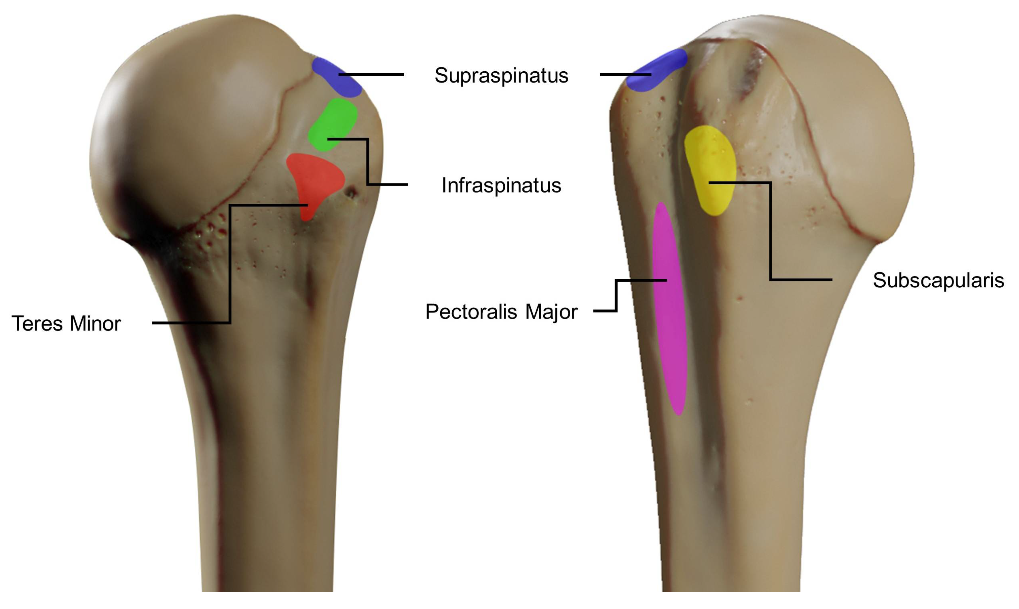
2.2. Muscles, Tendons, and Movements

As well as the main parts of the proximal humerus anatomy, the forces that the muscles and tendons generate on the bone are equally important when running an FEA, since they are responsible for the movement of the bone in the simulation and the reaction forces caused by the combination of these loads, which allow us to perform multiple analyses using an FEA. Thus, knowing which muscle and tendons have an effect on the bone, and to what magnitude depending on the specific movement, grants us the ability to replicate the behavior of a real patient in a simulation.
The proximal humerus is constantly subjected to torsion, compression, flexion, tension, and the combination of these, caused by combined forces and torques induced by the muscles and tendons attached to it (Figure 2), allowing shoulder movement and establishing the movement range. The humeral shaft is attached to the deltoid and pectoralis major. Attached to the greater tuberosity are the supraspinatus, infraspinatus, and teres minor, and positioned superior, posterosuperior, and posterior, respectively. For the lesser tuberosity, only the subscapularis is attached [13,16,36,37,42]. The balance between the deltoid and rotator cuff (supraspinatus, infraspinatus, subscapularis, supraspinatus, and teres minor) provides the correct variable forces to move the arm naturally.
If we isolate the natural movements of the shoulder, we obtain three main movements and their counter-movements. First, we have the flexion and extension movements, which consist of raising the limb forward and backward from the sagittal plane, respectively. The supraspinatus and infraspinatus have significant roles in flexion, unlike in extension where the subscapularis does the work [43]. Then, there is abduction and adduction, which are the movement of the limb away and towards the midplane of the coronal plane, respectively. For abduction, the use of the muscle and tendon will vary depending on the elevation angle. The supraspinatus has a greater impact at the beginning of the elevation, then the deltoid becomes more significant. In adduction, the pectoralis major does the work [44]. Finally, internal/external rotation consists of arm rotation towards/away from the centerline of the coronal plane. The muscles and tendons used in external rotation are the infraspinatus and teres minor. In the counterpart movement, the internal rotation uses the subscapularis and pectoralis major most [45]. This series of movements is generally used to study the progress of rehabilitation, but also for biomechanical analysis and experimentation.

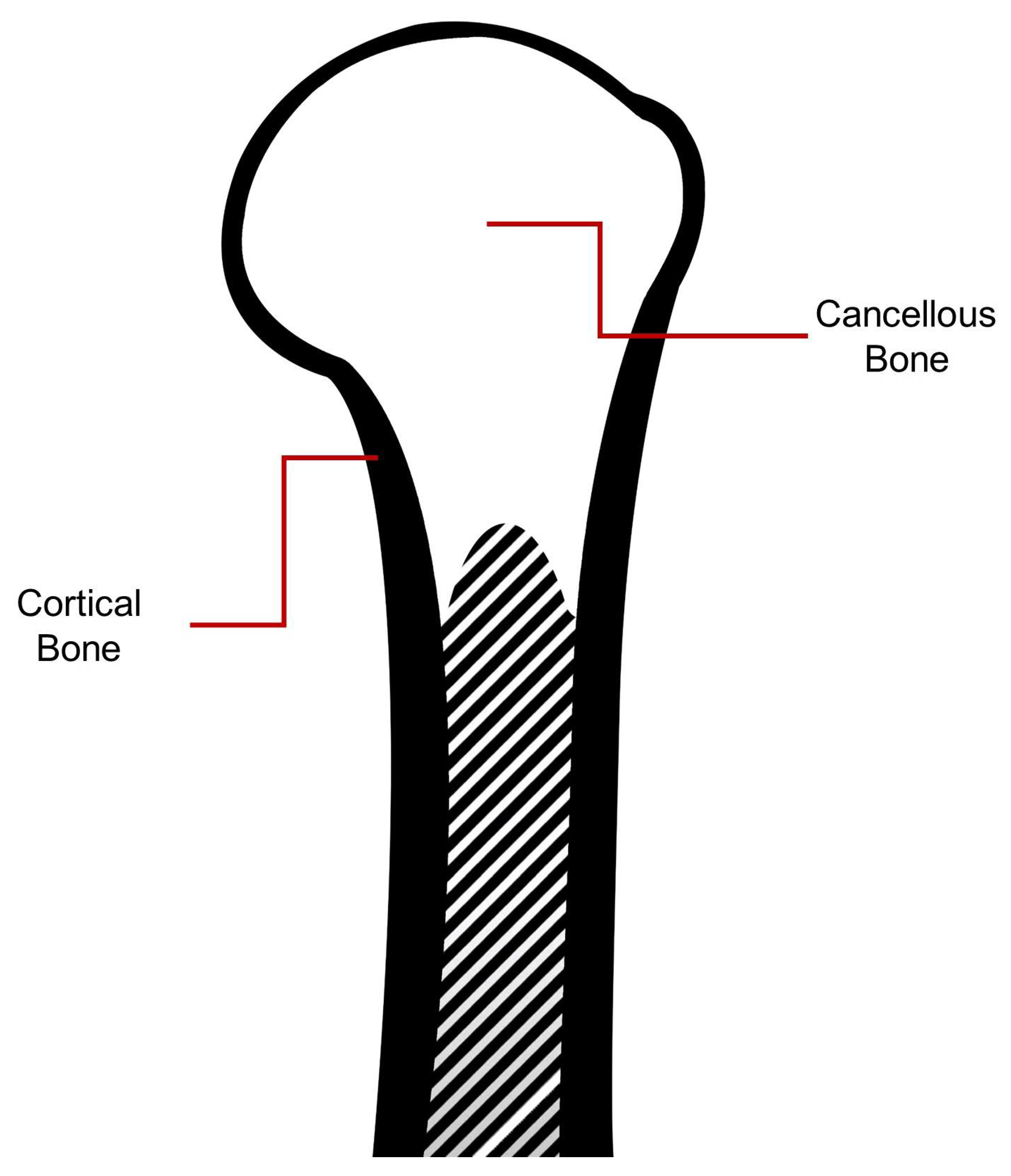
2.3. Bone Composition: Proximal Humerus

As a long bone, the proximal humerus is composed macroscopically of cancellous bone and cortical bone (Figure 3). The proportions between them will always vary, depending on age, comorbidities, bone diseases, and so forth. The cortical bone forms the external cortex of the bone, and can be found in the shafts (diaphysis) of long bones. Its porosity is low, being a more compact and dense bone tissue, varying from 5% to 30%. Almost 80% of the body’s total bone mass is cortical bone. On the contrary, cancellous bone is less dense, with porosity of up to 90%, being softer and more flexible than cortical tissue [18].
The shaft of the proximal humerus is mainly cortical bone, and shows the highest bone mineral density (BMD) values of the proximal humerus due to its compactness and thickness. However, its thickness gradually decreases towards the humeral head [4]. The humeral head is made primarily of cancellous bone, covered by a thin layer of cortical bone as a cortex [3,4,16].

3. Biomechanical FEA Studies for Proximal Humerus Fractures

According to the recent literature, most proximal humerus fracture studies using FEA tend to investigate factors involving open reduction and internal fixation (ORIF) treatment with a locking plate [5,28,29,30,31,33], due to the popularity of the treatment in the last few years, and also because of the high failure rate it has. Biomechanical studies turn around this treatment, investigating either the bone behavior or the effects of the locking plate configuration (Table 1); in any case, the interaction of both is relevant.
The predominant studies are those that evaluate the effect of a parameter, be it the bone or the locking plate; for example, the locking plate position [29], the screw hole style [5], and the insertion angle of the screws [31], among others. Each of these studies aims for treatment optimization and/or failure risk prediction. There are also other types of proximal humerus fracture studies, such as those who study the nature of a fracture itself, like the research by Dahan et al. [3]. A comparison is presented in Table 1.
Since a proximal humerus fracture can be presented in several forms, it is difficult to consider them all in one specific study, mainly due to the scope of the projects. That is why almost all studies of this type are limited to a single fracture pattern. Today, the majority of researchers are investigating proximal humerus 3-part fractures [15,29,30,31,33,46], because of the actual recurrence of the pattern in the clinical field [2,17,36,47,48]. The 3-part fracture (AO/OTA 11B1.1) mostly involves the surgical neck and greater tuberosity. The 2-part fracture (AO/OTA 11A2.1) patterns involving the surgical neck are not as relevant as they once were, but can still be useful for some researchers, considering the simplicity of the fracture pattern; for example, the studies by Jabran et al. [28], Zhang et al. [5], Dahan et al. [3], and Mendoza-Muñoz et al. [49]. The 2-part fracture is considered a simple fracture because only one bone segment is displaced from the rest of the bone, and usually the fracture occurs in the surgical neck; on the other hand, even though 3-part fractures commonly involve the surgical neck as well, there are two displaced segments instead of one. As Neer suggested, a 3-part fracture will mainly involve the surgical neck and the lesser or greater tubercle [36,39,41].
Mechanical tests in this type of study will always attempt to replicate natural shoulder movements involving the muscle-tendons forces and torques, or involve a specific exercise with external loads acting on the shoulder; this depends on the particular study objectives (Table 1). For veracity of the study results, the selected mechanical test must be validated before running a simulation. Preferable mechanical tests to evaluate the proximal humerus or the locking plate are bending, compression, and torsion [16,50], and sometimes a combination of them. However, in the literature we found everything from the simplest compression test, with just an axial load applied, to the most complex, considering all the muscles and tendons that affect the proximal humerus at different magnitudes for each simulated movement. The research run by Röderer et al. [51] is generally used to validate compression studies, as well as the study by Unger et al. [52], who physically tested a fractured proximal humerus with ORIF under a bending and axial rotation test setup. The review carried out by Mendoza-Muñoz et al. [53] shows another perspective of FEA studies of the proximal humerus with locking plates.

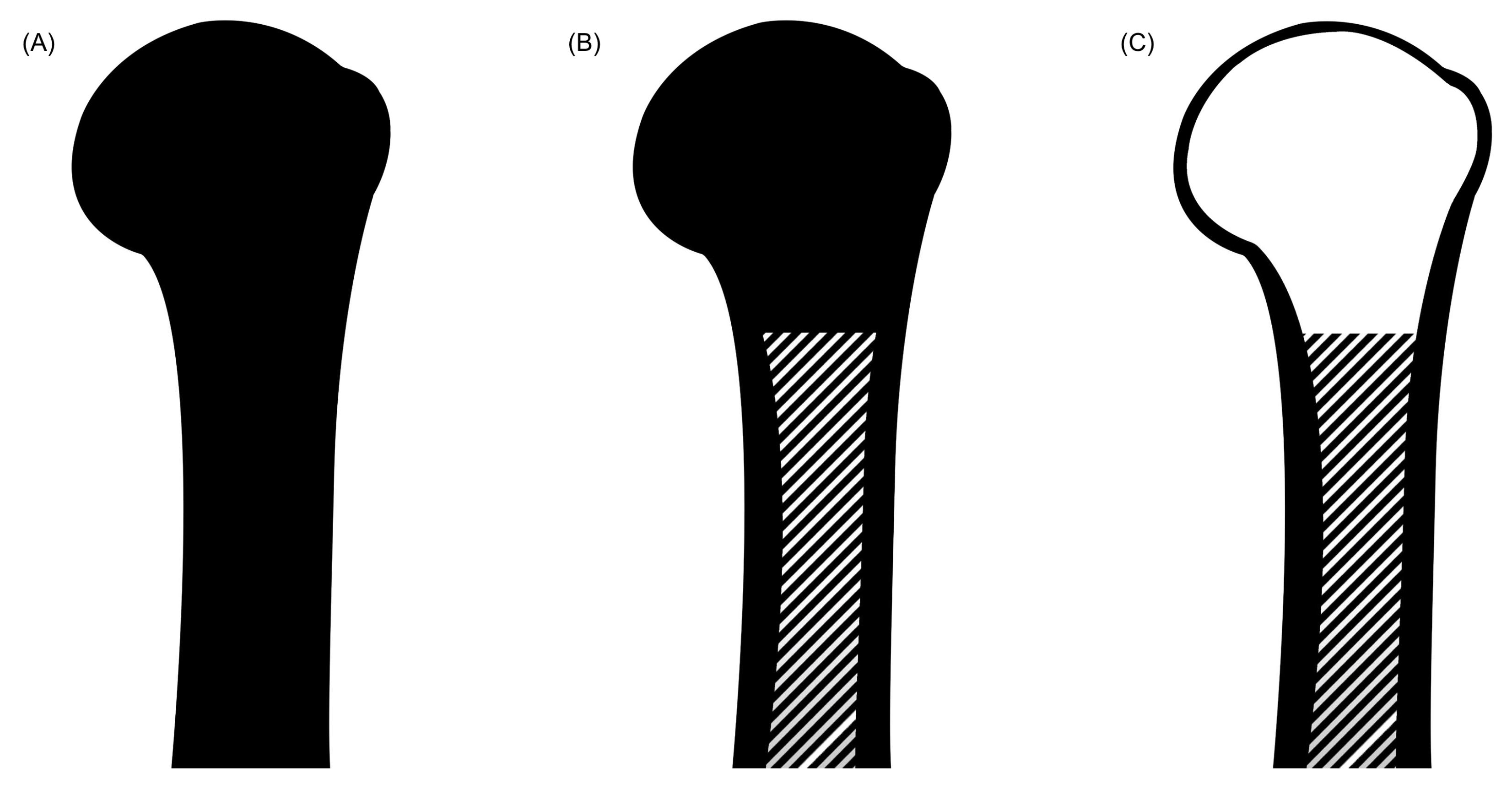
4. Simplification of the Geometry Characteristics of the Bone

The bone is an anisotropic material, which means that its mechanical properties will vary depending on the applied load direction [1,54,55]. This bone structure makes it difficult to simulate its behavior in FEA, which forces researchers to simplify the bone 3D model characteristics for their studies, to study the bone as a “conventional” material. Perren stated that bone anisotropy is not significant in ORIF, so it can be ignored when treating bone as a material [55]. The literature corroborates this, showing that using isotropic material properties for the bone is sufficient for analysis under simple loads [3,5,23,24,25,26,28,30,54,56].
In the specific case of the proximal humerus, model simplification will vary depending on the research objectives and resources. Three forms of modeling are commonly used. The first is the easiest, but the least close to reality. It consists of a complete solid model of the humerus, without distinguishing between cancellous and cortical bone (Figure 4A). An example of this approach is the 3D models used in the research by Chaudhry et al. and Shaikh et al. [25,26]. The next method, which is less common, consists of two main parts: the diaphysis and the humeral head, where the humeral head is completely solid considering that it is almost all cancellous bone, and the diaphysis is empty due to the medullary cavity (Figure 4B). This type of model was used in the study by Jabran et al. [28], although he did not distiguish between the cancellous and cortical tissues, since he assigned the same elastic modulus for both sections (humeral head and diaphysis). The third and last form is the most complex due to cancellous bone variability, and is the most similar to a real bone. The cortical and cancellous bone tissues are separated, and each one has its own mechanical properties (Figure 4C). The differentiation of these tissues can be achieved by establishing a threshold according to the density of each tissue, identifying each one with the help of software such as Mimics 17.0 (Materialise, Belgium), PTC Creo 2.0 (Parametric Technologies Corp., Needham, MA, USA), MATLAB (MathWorks, USA), or the filling algorithm [32] implemented in Medtool 3.8 (Dr. Pahr Ingenieurs e.U., Austria). However, it is sometimes difficult to identify the diffuse boundaries of the cancellous bone, and it takes experience and time to achieve an acceptable model. This last type of humerus model can be found in the studies by Dahan et al. [3], Fletcher et al. [29,30], Mischler et al. [31], Zhang et al. [5], and Zhao et al. [20].
The accuracy of the FEA results obtained with each model simplification technique cannot be directly compared, since the geometry of the model is only one factor in a multifactorial system such as FEA, and there is no standard procedure for this process; furthermore, the studies differ in the metrics used, mechanical tests, and objetives. Therefore, the simpliest way to evaluate the effectiviness of the model simplification technique is through the words of the researcher, comparing their model with the literature or a physical validation test. Thus, it can be seen that the use of a solid proximal humerus model, without distinguishing bone tissues, as used by Chaundry et al. [25], shows minimal levels of bone stress compared to the literature. This is as expected, as it is the farthest model from an actual bone, and the model was not validated with a physical test. The model simplification of a solid humeral head and empty diaphysis, such as the one that Jabran et al. [28] used in their study, shows better results, even when the mechanical properties were treated the same as for the whole bone. The bone model could be validated with an in vitro test, taking as reference the bending load of the bone and achieving an FEA bone bending load of 0.728% less than in the physical test, as well as providing results comparable to those of the literature. However, as expected, the most widely used proximal humerus simplification model, where both cancellous and cortical bone are distinguished, shows the best results according to the validation tests of each study. Firstly, in the study by Dahan et al. [3], who also validated their model with an in vitro test, an excellent correlation of R 2 = 0.982 for the bone strain in the FEA and in vitro experiment was found. The studies carried out by Fletcher et al. [29,30] and Mischler [31], which used a framework specifically designed to optimize the FEA process for proximal humerus fracture analyses treated with locking plates and included the computational framework designed by Varga et al. [42], also performed multiple validations of the proximal humerus model offered in the framework, taking as reference the strain around the the locking plate screws and obtaining very high correlation values in two different test scenarios: R 2 = 0.904 and R 2 = 0.99 . Last but not least, the model used for the study carried out by Zhao et al. [20], that was validated through an in vitro test using bone dissplacement as the validation metric, obtained 3.46% and 5.69% for the tension and torsion tests, respectively. A small displacement was found compared to the in vitro test, however it showed the precision of the FEA bone model used.

5. From Reality to 3D Model: Mechanical Properties Assignment

When running a bone simulation, you should not only simplify the geometry, but also the mechanical properties values. The minimum required properties that a conventional material needs for a mechanical simulation are the elastic modulus (E) and the Poisson ratio (ν), so they must be defined for both cortical and cancellous bone tissues. The elastic modulus (1) is defined by the relationship between stress (σ) and strain (ϵ) [50]. It is also a measure of the material stiffness; that is, the higher the value of the elastic modulus, the higher the stiffness.
E = σ ϵ    
The Poisson’s ratio defines the relationship between transverse and longitudinal deformation; that is, it describes the behavior of the material perpendicular to the applied load [57]. These values must be subject-specific according to the research. Units of the elastic modulus that are most used are GPa or MPa, and the Poisson ratio has no units.
The Poisson ratio is the same for almost all metals as for bone, and the literature shows that the preferred value for the Poisson ratio is ν = 0.3 [3,5,20,23,24,26,28,31,33,42,54,56,58]. Notwithstanding the agreement between studies, a few have proposed a “slightly” different Poisson’s ratio around ν = 0.3 for bone tissues. For example, in the proximal femur fracture research by Keyak and Falkinstein [59], they assumed ν = 0.4 for their experimentation. Another femur study by Goshulak et al. [24] used ν = 0.26 for cortical bone. Chaudhry et al. [25] and Shaikh et al. [26] used ν = 0.33 for all bone mass values (cortical and cancellous).

5.1. Cortical Bone

The elastic modulus of cortical bone is easier to obtain than that of cancellous bone, due to its high density and lower porosity. It can be obtained directly from a mechanical test on a cadaveric bone, or by converting the vBMD (volumetric bone mineral density) values obtained from quantitative computer tomography (QCT), expressed as grams of hydroxyapatite per centimeter cubed ( gHA / cm 3 ) [4,60]. The vBMD is calculated from the measure obtained by the response of the QTC to the phantom’s calibrated regions, which are usually concentrations of calcium hydroxiapatite ( HA ) and provide equivalent denstinties to BMD in gHA / cm 3 [58,59,60].
As explained before, we can find the thickest cortical bone in the proximal humerus diaphysis. Therefore, to convert the vBMD values to the elastic modulus, there are some equations in the literature; for example, the most referenced equation [30,31,33,42] is from the Dragomir-Daescu et al. study [56], which is based on research by Morgan et al. [61], where the ρ ( gHA / cm 3 ) is the equivalent density to the BMD value obtained from the QTC, as seen in Equation (2).
E   ( M P a ) = 14 , 664 ρ 1.49
Equation (3), of Yosibash et al. [54], is based on the studies by Schileo et al. [58] and Keller [62]:
E ( M P a ) = 10 , 200 ρ 2.01
The selection of the formula is based on the one that best suits the particular study, or the use of both could be an option to validate the results. Several studies already give the cortical bone elastic modulus [5,20,33,55] as ranging from 12 to 20 GPa. A comparison of the values is shown in Table 2.

5.2. Cancellous Bone

Cancellous bone is a more complex tissue due to its aforementioned high porosity and variable density. Additionally, the characteristics (comorbidities, age, bone diseases, gender) of the studied patient affect the bone quality and mechanical properties. Due to these factors, the BMD and elastic modulus could have large variations depending on the subject or group of people being studied.
As for cortical bone, the cancellous bone elastic modulus can be obtained by converting the vBMD values. The literature [30,31,33,42] shows that the same equation from Dragomir-Daescu et al. [56] works for both cancellous and cortical tissues. This is different from the Yosibash et al. formula, which proposed two different equations if it was merely trabecular bone, or a transition between cortical and cancellous bone.
In contrast, Yosibash et al. [54] proposed an equation and an arbitrary elastic modulus value, both dependent on the vBMD ( ρ , gHA / cm 3 ) value. Equation (4) is for merely trabecular bone, and the given elastic modulus (5) for the transition between cortical and trabecular bone is:
I f   0.3   <   ρ   < 0.486 ,   t h e n   E = 2 , 398   M P a ,
I f   ρ 0.3 ,   t h e n   E ( M P a ) = 33 , 900 ρ 2.2
For the humerus, depending on the study, a direct elastic modulus value or a vBMD range could be used; generally, when the study uses a range of vBMD values for cancellous bone, it is specifically for the humeral head, because as mentioned before, most of the humeral head is composed of cancellous bone. In other matters, if an elastic modulus value is defined, it is used for all the cancellous bone in the humerus. Table 3 shows the elastic modulus given for cancellous bone by some researchers [5,20,33], ranging from 0.1 to 1.061 GPa. Table 4 exhibits the vBMD values for the cancellous bone in the humeral head, used or measured in some studies [4,30,31,42,51,63], with a range of 17.8–178.2 mgHA / cm 3 .

6. Proximal Humerus Meshing Properties

The meshing process plays an important role in FEA: the time consumption of the simulation and accuracy of results will depend on the meshing quality and technique used. The mesh itself functions as a visual representation of the object of study, and shows its response to external loads. There is no standard configuration for the mesh—it will vary according to the investigator’s resources and knowledge, and the study’s aims. The mesh is a computational grid composed of polyhedral elements; nowadays, the types of elements most used are the 8-noded hexahedra and 4-noded tetrahedra [64]. To sum up, the quality of the mesh and the time needed will depend on the aspect ratio of the element. The smaller the element size, the higher the quality, but also the machine/human time will increase [19,64].
Meshing a bone is specifically difficult due to its imperfect geometry; thus, some experience and skill may be required in some cases. Sometimes, a combination of techniques is the best option. To find the most used properties to mesh the proximal humerus, the following parameters will be taken as a reference: mesh type, element type, number of nodes, and element edge length.
As seen in Table 5, the literature [3,20,27,28,31,33,42,65,66] exhibits the great preference for tetrahedral mesh (C3D10) over hexahedral mesh, and the quadratic element over the linear element. Studies tend not to specify the number of nodes for each element, but the number of total mesh elements, although some studies report the use of 8- and 10-nodes. The element edge length is usually about 0.85–5 mm, and fine mesh is preferable for accurate results.

7. Discussion

It is evident that different researchers use different techniques and properties to characterize the proximal humerus, but every one of them follows the same basis. The techniques used range from the simplest to the most complex, and are mainly affected by the researcher’s resources, leading to attempts to further simplify the bone characterization process.
However, some characteristics are unavoidable in any study of the proximal humerus, such as the bone anatomy, which has to be the same in any model, unlike the bone geometry, which will be specific to the patient of the study. The muscles cannot be ignored but can be simplified, which generally occurs due to the complexity of simulating their behavior. Researchers tend to simplify the forces and torques generated from the muscle’s attachments using force vectors and movement constraints. The most accurate results would be obtained with the conditions closest to reality. Thus, the best way to simulate natural shoulder movements (abduction, flexion, internal rotation, etc.) is to consider the muscles involved (supraspinatus, infraspinatus, subscapularis, etc.), as well the joint reaction forces generated, as in the research by Varga et al. [42]. However, this is not the only way. Bergmann et al. [67] validated the use of a vector force in a coordinate system for flexion and abduction in elderly subjects; later, this technique was replicated in other studies, such as those by Razfar et al. [27], Reeves et al. [66], and Dahan et al [3].
The bone composition of the proximal humerus is one of the most modified and simplified characteristics in studies, due to the anisotropic nature of bones. For the sake of the studies, the use of isotropic nature has been validated and accepted for biomechanics testing of the proximal humerus and other bones. There are a few ways to simplify the humerus model bone composition, such as making a solid humerus model and using the law of mixtures [68] for composite materials to combine the properties of cortical and cancellous bone. This will not give the best results, as there is no validation process and the model differs substantially from a real bone. However, if precision of the results is sought, the separation of both tissues seems a better option and closer to reality, according to the correlation values obtained from validation tests.
The assignment of mechanical properties, especially the elastic modulus, will vary considerably between studies due to the particularities of the subject-specific study model. There are different formulas to convert vBMD values into the elastic modulus. Some other proposed formulas were evaluated in a previous Yosibash et al. study [22], which concluded that the best correlation to experimental observations was the Keyak and Falkinstein equation [59] that he used for his proposal. The Dragomir-Daescu et al. formula [56] also refers to the Keyak and Falkinstein research, but is based primarily on the research by Morgan et al. [61]. Most of the equations are well-validated, regardless of whether they were mainly made for converting the BDM values of the proximal femur into the elastic modulus, and they have also been used in proximal humerus research, such as that by Dahan et al. [3] and Inzana et al. [33]. It should be noted that no equation is definitive. The research by Morgan et al. states that there is no single equation, nor general elastic modulus-density relationship; they are only approximations to reality, so their selection will depend on which is more useful to the specific study and which gives expected values compared to the study data or reference data.
For the mesh, the information collected does not show any significant differences. Almost all researchers agree that the tetrahedral mesh (C3D10) is better for testing the proximal humerus. The element type is preferably quadratic rather than linear for accurate results, with about eight or ten nodes per element. Researchers tend to use fine meshes over coarse, where the maximum length of the element is not more than 5 mm, and the total number of elements is an approximate mean of 640,000. The mesh should be model-specific. As studies have shown, using a discretization method or refinement technique is ideal. Most of the reviewed research coincides with the use of a mesh convergence analysis, taking the strain and/or stiffness as the convergence metrics. Another way to validate the mesh configuration is to compare the results of the selected metric with those obtained by using a p- and h-refinement method, as Mischler et al. [31] did, to see how much it differs from the original mesh and the correlation between them. In fact, all studies have tended to look for a mesh that offers the best solution time without compromising the accuracy of the results, and the only way to achieve this is through experimentation with the models and resources of your own.

8. Conclusions

This review highlights the need for a characterization standard for the proximal humerus modeling process; that is, a series of parameters and model characteristics for the tridimensional bone model, which has been shown to better represent the real mechanical behavior of the proximal humerus and to be applicable to any patient-specific model, regardless of the geometry of the bone or the patient’s BMD, and finally, which serves as a reference to compare results or validate FEA studies. As noted, recent studies have been considering this too, but with no clear path to follow. It is evident that most of the proximal humerus studies have attempted to optimize ORIF treatment, but without any standard in the modeling and testing processes, it is difficult to compare results between studies. Furthermore, the proximal humerus FEA studies do not share similar characteristics of the 3D model, nor the mesh parameters used. As explained before, the closer to reality the bone model and simulation are, the better the results; in other words, the more detailed the proximal humerus model and the finer the mesh, the greater the accuracy of the results. There are some studies, such as that of Varga et al. [42], which have tried to standardize the proximal humerus fracture tests and its modeling and meshing processes, with the aim of obtaining more comparable results. His framework offers a database of bone quality samples from a group of adults ranging between 64 and 98 years of age. Additionally, using the 3D proximal humerus model made by Kamer et al. [4], another study also attempted to standardize the geometry of the adult proximal humerus bone from a group of 58 donated proximal humerus samples. In summary, there is currently no definitive way to characterize the proximal humerus for FEA, but the similarities of the existing studies show that there are some parts of the process that can be standardized, and the existing data is sufficient to allow this to occur.

Author Contributions

Conceptualization, A.D.C.-F., I.M.-M., and Á.G.-Á.; methodology, S.E.C.-S.; investigation, A.D.C.-F., I.M.-M., M.S.-H., and A.M.C.; writing—original draft preparation, A.D.C.-F. and I.M.-M.; writing—review and editing, S.E.C.-S. and Á.G.-Á. All authors have read and agreed to the published version of the manuscript.

Funding

This research received no external funding.

Acknowledgments

The authors express their gratitude to the Mexican National Council for Science and Technology (CONACYT) for the research grant to Angel Daniel Castro Franco (CVU No. 983649). The authors would like to thank the Autonomous University of Baja California (UABC) for facilitating access to and use of its facilities and equipment.

Conflicts of Interest

The authors declare no conflict of interest.

References

  1. Al Anouti, F.; Taha, Z.; Shamim, S.; Khalaf, K.; Al Kaabi, L.; Alsafar, H. An insight into the paradigms of osteoporosis: From genetics to biomechanics. Bone Rep. 2019, 11, 100216. [Google Scholar] [CrossRef] [PubMed]
  2. Court-Brown, C.M.; Duckworth, A.D.; Clement, N.D.; McQueen, M.M. Fractures in older adults. A view of the future? Injury 2018, 49, 2161–2166. [Google Scholar] [CrossRef] [PubMed]
  3. Dahan, G.; Trabelsi, N.; Safran, O.; Yosibash, Z. Finite element analyses for predicting anatomical neck fractures in the proximal humerus. Clin. Biomech. 2019, 68, 114–121. [Google Scholar] [CrossRef] [PubMed]
  4. Kamer, L.; Noser, H.; Popp, A.W.; Lenz, M.; Blauth, M. Computational anatomy of the proximal humerus: An ex vivo high-resolution peripheral quantitative computed tomography study. J. Orthop. Transl. 2016, 4, 46–56. [Google Scholar] [CrossRef] [Green Version]
  5. Zhang, Y.-K.; Wei, H.-W.; Lin, K.-P.; Chen, W.-C.; Tsai, C.-L.; Lin, K.-J. Biomechanical effect of the configuration of screw hole style on locking plate fixation in proximal humerus fracture with a simulated gap: A finite element analysis. Injury 2016, 47, 1191–1195. [Google Scholar] [CrossRef]
  6. Baidwan, N.; Naranje, S. Epidemiology and recent trends of geriatric fractures presenting to the emergency department for United States population from year 2004–2014. Public Health 2017, 142, 64–69. [Google Scholar] [CrossRef]
  7. Hamidi, M.; Joseph, B. Changing Epidemiology of the American Population. Clin. Geriatr. Med. 2019, 35, 1–12. [Google Scholar] [CrossRef]
  8. United Nations. World Population Prospects 2019; Highlights: New York, NY, USA, 2019. Available online: https://bit.ly/2MXgwm4 (accessed on 16 August 2019).
  9. Khanuja, K.; Joki, J.; Bachmann, G.; Cuccurullo, S.; Joki, J. Gait and balance in the aging population: Fall prevention using innovation and technology. Maturitas 2018, 110, 51–56. [Google Scholar] [CrossRef]
  10. Reske-Nielsen, C.; Medzon, R. Geriatric Trauma. Emerg. Med. Clin. N. Am. 2016, 34, 483–500. [Google Scholar] [CrossRef]
  11. Ronthal, M. Gait Disorders and Falls in the Elderly. Med Clin. N. Am. 2019, 103, 203–213. [Google Scholar] [CrossRef]
  12. World Health Organization. World Report on Ageing and Health; World Health Organization: Geneva, Switzerland, 2015; pp. 3–223.
  13. Khoriati, A.; Antonios, T.; Bakti, N.; Mohanlal, P.; Singh, B. Outcomes following non operative management for proximal humerus fractures. J. Clin. Orthop. Trauma 2019, 10, 462–467. [Google Scholar] [CrossRef] [PubMed]
  14. Nowak, L.L.; Dehghan, N.; McKee, M.D.; Schemitsch, E.H. Plate fixation for management of humerus fractures. Injury 2018, 49, S33–S38. [Google Scholar] [CrossRef]
  15. Woodmass, J.M.; Welp, K.; Chang, M.J.; Borque, K.A.; Wagner, E.R.; Warner, J.J. Three- and four-part proximal humerus fractures in the elderly: Eminence versus evidence. Semin. Arthroplast. 2017, 28, 102–108. [Google Scholar] [CrossRef]
  16. Goharian, A.; Kadir, M.R. Humerus Trauma Plating Fixation. In Trauma Plating Systems; Elsevier BV: Amsterdam, The Netherlands, 2017; pp. 183–215. [Google Scholar]
  17. Padegimas, E.M.; Zmistowski, B.; Lawrence, C.; Palmquist, A.; Nicholson, T.A.; Namdari, S. Defining optimal calcar screw positioning in proximal humerus fracture fixation. J. Shoulder Elb. Surg. 2017, 26, 1931–1937. [Google Scholar] [CrossRef]
  18. Boyd, S.; Müller, R. Microimaging. In Principles of Bone Biology, 4th ed.; Bilezikian, J.P., Martin, T.J., Clemens, T.L., Rosen, C.J., Eds.; Elsevier: Amsterdam, The Netherlands, 2020; pp. 1833–1856. [Google Scholar]
  19. Simkins, D.C.; Alford, J.B. The Role of Computational Tools in Biomechanics. In Biomechanics of the Female Pelvic Floor; Elsevier: Amsterdam, The Netherlands, 2016; pp. 351–366. [Google Scholar]
  20. Zhao, L.-M.; Tian, D.-M.; Wei, Y.; Zhang, J.-H.; Di, Z.-L.; He, Z.-Y.; Hu, Y.-C. Biomechanical Analysis of a Novel Intercalary Prosthesis for Humeral Diaphyseal Segmental Defect Reconstruction. Orthop. Surg. 2018, 10, 23–31. [Google Scholar] [CrossRef] [PubMed] [Green Version]
  21. Kim, H.; Kim, S.-H.; Chang, S.-H. Finite element analysis using interfragmentary strain theory for the fracture healing process to which composite bone plates are applied. Compos. Struct. 2011, 93, 2953–2962. [Google Scholar] [CrossRef]
  22. Yosibash, Z.; Trabelsi, N.; Milgrom, C. Reliable simulations of the human proximal femur by high-order finite element analysis validated by experimental observations. J. Biomech. 2007, 40, 3688–3699. [Google Scholar] [CrossRef]
  23. Marcián, P.; Narra, N.; Borák, L.; Chamrad, J.; Wolff, J. Biomechanical performance of cranial implants with different thicknesses and material properties: A finite element study. Comput. Boil. Med. 2019, 109, 43–52. [Google Scholar] [CrossRef]
  24. Goshulak, P.; Samiezadeh, S.; Aziz, M.S.; Bougherara, H.; Zdero, R.; Schemitsch, E.H. The biomechanical effect of anteversion and modular neck offset on stress shielding for short-stem versus conventional long-stem hip implants. Med. Eng. Phys. 2016, 38, 232–240. [Google Scholar] [CrossRef]
  25. Chaudhry, V.; Kumar, K.N.; Panwar, K.S.; Shaikh, A.; Avikal, S. Static structural analysis of humerus bone to find out the load at which fracture occurs and predict suitable alternative materials for bone implants. Mater. Today: Proc. 2020, 26, 1701–1706. [Google Scholar] [CrossRef]
  26. Shaikh, A.; Negi, S.; Aswal, A.; Chaudhry, V.; Kishore, C.; Kumar, K.N. Modal analysis of Humerus bone using CAE tools. Mater. Today: Proc. 2020, 26, 2108–2112. [Google Scholar] [CrossRef]
  27. Razfar, N.; Reeves, J.M.; Langohr, D.G.; Willing, R.; Athwal, G.S.; Johnson, J.A. Comparison of proximal humeral bone stresses between stemless, short stem, and standard stem length: A finite element analysis. J. Shoulder Elb. Surg. 2016, 25, 1076–1083. [Google Scholar] [CrossRef] [PubMed]
  28. Jabran, A.; Peach, C.; Zou, Z.; Ren, L. Parametric Design Optimisation of Proximal Humerus Plates Based on Finite Element Method. Ann. Biomed. Eng. 2019, 47, 601–614. [Google Scholar] [CrossRef] [PubMed] [Green Version]
  29. Fletcher, J.W.A.; Windolf, M.; Richards, G.; Gueorguiev, B.; Buschbaum, J.; Varga, P. Importance of locking plate positioning in proximal humeral fractures as predicted by computer simulations. J. Orthop. Res. 2019, 37, 957–964. [Google Scholar] [CrossRef] [PubMed]
  30. Fletcher, J.W.; Windolf, M.; Richards, R.G.; Gueorguiev, B.; Varga, P. Screw configuration in proximal humerus plating has a significant impact on fixation failure risk predicted by finite element models. J. Shoulder Elb. Surg. 2019, 28, 1816–1823. [Google Scholar] [CrossRef] [PubMed]
  31. Mischler, D.; Windolf, M.; Gueorguiev, B.; Nijs, S.; Varga, P. Computational optimisation of screw orientations for improved locking plate fixation of proximal humerus fractures. J. Orthop. Transl. 2020. [Google Scholar] [CrossRef]
  32. Pahr, D.H.; Zysset, P.K. From high-resolution CT data to finite element models: Development of an integrated modular framework. Comput. Methods Biomech. Biomed. Eng. 2009, 12, 45–57. [Google Scholar] [CrossRef]
  33. Inzana, J.A.; Varga, P.; Windolf, M. Implicit modeling of screw threads for efficient finite element analysis of complex bone-implant systems. J. Biomech. 2016, 49, 1836–1844. [Google Scholar] [CrossRef]
  34. Boileau, P.; Walch, G. The three-dimensional geometry of the proximal humerus. Implications for surgical technique and prosthetic design. J. Bone Jt. Surg. Br. 1997, 79, 857–865. [Google Scholar] [CrossRef]
  35. Pearl, M.L.; Volk, A.G. Coronal plane geometry of the proximal humerus relevant to prosthetic arthroplasty. J. Shoulder Elb. Surg. 1996, 5, 320–326. [Google Scholar] [CrossRef]
  36. Gogna, R.; Bhabra, G.; Modi, C.S. Fractures of the proximal humerus: Overview and non-surgical management. Orthop. Trauma 2019, 33, 315–321. [Google Scholar] [CrossRef]
  37. Hinson, J.A. Anatomy and Classification of Proximal Humerus Fractures. In Proximal Humerus Fractures; Springer International Publishing: Cham, Switzerland, 2015; pp. 1–22. [Google Scholar]
  38. Iannotti, J.; Gabriel, J.; Schneck, S.; Evans, B.; Misra, S. The normal glenohumeral relationships. An anatomical study of one hundred and forty shoulders. JBJS 1992, 74, 491–500. [Google Scholar] [CrossRef]
  39. Neer, C.S. THE CLASSIC: Displaced Proximal Humeral Fractures. Clin. Orthop. Relat. Res. 2006, 442, 77–82. [Google Scholar] [CrossRef] [PubMed]
  40. Hertel, R.; Hempfing, A.; Stiehler, M.; Leunig, M. Predictors of humeral head ischemia after intracapsular fracture of the proximal humerus. J. Shoulder Elb. Surg. 2004, 13, 427–433. [Google Scholar] [CrossRef]
  41. Meinberg, E.G.; Agel, J.; Roberts, C.S.; Karam, M.D.; Kellam, J.F. Fracture and Dislocation Classification Compendium—2018. J. Orthop. Trauma 2018, 32, S1–S10. [Google Scholar] [CrossRef]
  42. Varga, P.; Inzana, J.A.; Gueorguiev, B.; Südkamp, N.P.; Windolf, M. Validated computational framework for efficient systematic evaluation of osteoporotic fracture fixation in the proximal humerus. Med. Eng. Phys. 2018, 57, 29–39. [Google Scholar] [CrossRef]
  43. Wattanaprakornkul, D.; Cathers, I.; Halaki, M.; Ginn, K.A. The rotator cuff muscles have a direction specific recruitment pattern during shoulder flexion and extension exercises. J. Sci. Med. Sport 2011, 14, 376–382. [Google Scholar] [CrossRef]
  44. Otis, J.C.; Jiang, C.-C.; Wickiewicz, T.L.; Peterson, M.G.E.; Warren, R.F.; Santner, T.J. Changes in the moment arms of the rotator cuff and deltoid muscles with abduction and rotation. J. Bone Jt. Surg. Am. 1994, 76, 667–676. [Google Scholar] [CrossRef]
  45. Kuechle, D.K.; Newman, S.R.; Itoi, E.; Niebur, G.L.; Morrey, B.F.; An, K.-N. The relevance of the moment arm of shoulder muscles with respect to axial rotation of the glenohumeral joint in four positions. Clin. Biomech. 2000, 15, 322–329. [Google Scholar] [CrossRef]
  46. Vicenti, G.; Antonella, A.; Filipponi, M.; Conserva, V.; Solarino, G.; Carrozzo, M.; Moretti, B. A comparative retrospective study of locking plate fixation versus a dedicated external fixator of 3- and 4-part proximal humerus fractures: Results after 5 years. Injury 2019, 50, S80–S88. [Google Scholar] [CrossRef]
  47. Handoll, H.H.; Keding, A.; Corbacho, B.; Brealey, S.D.; Hewitt, C.; Rangan, A. Five-year follow-up results of the PROFHER trial comparing operative and non-operative treatment of adults with a displaced fracture of the proximal humerus. Bone Jt. J. 2017, 99, 383–392. [Google Scholar] [CrossRef] [PubMed] [Green Version]
  48. Passaretti, D.; Candela, V.; Sessa, P.; Gumina, S. Epidemiology of proximal humeral fractures: A detailed survey of 711 patients in a metropolitan area. J. Shoulder Elb. Surg. 2017, 26, 2117–2124. [Google Scholar] [CrossRef] [PubMed]
  49. Mendoza-Muñoz, I.; González-Angeles, A.; Jacobo-Galicia, G.; Castañeda, A.; Valenzuela-Gutiérrez, J. Análisis de los elementos principales en el diseño de placas de bloqueo en una fractura de 2-partes del cuello quirúrgico del húmero utilizando MEF y análisis estadístico. Matéria (Rio de Janeiro) 2018, 23. [Google Scholar] [CrossRef] [Green Version]
  50. Roe, S. Biomechanics of Fracture Fixation. Veter. Clin. N. Am. Small Anim. Pract. 2019, 50, 1–15. [Google Scholar] [CrossRef]
  51. Röderer, G.; Brianza, S.; Schiuma, D.; Schwyn, R.; Scola, A.; Gueorguiev, B.; Gebhard, F.; Tami, A. Mechanical Assessment of Local Bone Quality to Predict Failure of Locked Plating in a Proximal Humerus Fracture Model. Orthopedics 2013, 36, e1134–e1140. [Google Scholar] [CrossRef] [Green Version]
  52. Unger, S.; Erhart, S.; Kralinger, F.; Blauth, M.; Schmoelz, W. The effect of in situ augmentation on implant anchorage in proximal humeral head fractures. Injury 2012, 43, 1759–1763. [Google Scholar] [CrossRef]
  53. Mendoza-Muñoz, I.; González-Angeles, A.; Siqueiros-Hernández, M.; Montoya-Reyes, M. Biomechanical Principles Used in Finite Element Analysis for Proximal Humeral Fractures with Locking Plates. Med. Sci. Technol. 2017, 58, 128–136. [Google Scholar] [CrossRef]
  54. Yosibash, Z.; Mayo, R.P.; Dahan, G.; Trabelsi, N.; Amir, G.; Milgrom, C. Predicting the stiffness and strength of human femurs with real metastatic tumors. Bone 2014, 69, 180–190. [Google Scholar] [CrossRef]
  55. Perren, S.M. Basic Aspects of Internal Fixation. In Manual of Internal Fixation; Springer: Berlin/Heidelberg, Germany, 1991; Volume 53, pp. 1–158. [Google Scholar]
  56. Dragomir-Daescu, D.; Buijs, J.O.D.; McEligot, S.; Dai, Y.; Entwistle, R.C.; Salas, C.; Melton, L.J.; Bennet, K.E.; Khosla, S.; Amin, S. Robust QCT/FEA Models of Proximal Femur Stiffness and Fracture Load During a Sideways Fall on the Hip. Ann. Biomed. Eng. 2011, 39, 742–755. [Google Scholar] [CrossRef] [Green Version]
  57. Ling, B.; Wei, K.; Wang, Z.; Yang, X.; Qu, Z.; Fang, D. Experimentally program large magnitude of Poisson’s ratio in additively manufactured mechanical metamaterials. Int. J. Mech. Sci. 2020, 173, 105466. [Google Scholar] [CrossRef]
  58. Schileo, E.; Dall’Ara, E.; Taddei, F.; Malandrino, A.; Schotkamp, T.; Baleani, M.; Viceconti, M. An accurate estimation of bone density improves the accuracy of subject-specific finite element models. J. Biomech. 2008, 41, 2483–2491. [Google Scholar] [CrossRef] [PubMed]
  59. Keyak, J.; Falkinstein, Y. Comparison of in situ and in vitro CT scan-based finite element model predictions of proximal femoral fracture load. Med. Eng. Phys. 2003, 25, 781–787. [Google Scholar] [CrossRef]
  60. Knowles, N.K.; Reeves, J.M.; Ferreira, L. Quantitative Computed Tomography (QCT) derived Bone Mineral Density (BMD) in finite element studies: A review of the literature. J. Exp. Orthop. 2016, 3, 36. [Google Scholar] [CrossRef] [PubMed] [Green Version]
  61. Morgan, E.F.; Bayraktar, H.H.; Keaveny, T.M. Trabecular bone modulus–density relationships depend on anatomic site. J. Biomech. 2003, 36, 897–904. [Google Scholar] [CrossRef]
  62. Keller, T.S. Predicting the compressive mechanical behavior of bone. J. Biomech. 1994, 27, 1159–1168. [Google Scholar] [CrossRef]
  63. Schliemann, B.; Risse, N.; Frank, A.; Müller, M.; Michel, P.; Raschke, M.J.; Katthagen, J.C. Screws with larger core diameter and lower thread pitch increase the stability of locked plating in osteoporotic proximal humeral fractures. Clin. Biomech. 2019, 63, 21–26. [Google Scholar] [CrossRef]
  64. Wittek, A.; Miller, K. Computational biomechanics for medical image analysis. In Handbook of Medical Image Computing and Computer Assisted Intervention; Elsevier: Amsterdam, The Netherlands, 2020; pp. 953–977. [Google Scholar]
  65. Tilton, M.; Lewis, G.S.; Wee, H.B.; Armstrong, A.; Hast, M.W.; Manogharan, G. Additive manufacturing of fracture fixation implants: Design, material characterization, biomechanical modeling and experimentation. Addit. Manuf. 2020, 33, 101137. [Google Scholar] [CrossRef]
  66. Reeves, J.M.; Langohr, G.D.G.; Athwal, G.S.; Johnson, J.A. The effect of stemless humeral component fixation feature design on bone stress and strain response: A finite element analysis. J. Shoulder Elb. Surg. 2018, 27, 2232–2241. [Google Scholar] [CrossRef]
  67. Bergmann, G.; Graichen, F.; Bender, A.; Rohlmann, A.; Halder, A.; Beier, A.; Westerhoff, P. In vivo gleno-humeral joint loads during forward flexion and abduction. J. Biomech. 2011, 44, 1543–1552. [Google Scholar] [CrossRef]
  68. Gooch, J.W. Law of Mixtures. In Encyclopedic Dictionary of Polymers; Gooch, J.W., Ed.; Springer: New York, NY, USA, 2011; p. 421. [Google Scholar]
Figure 1. Proximal humerus anatomy, sectioned by colors: the humeral head (blue), greater (green) and lesser (red) tuberosities, anatomical neck (magenta), surgical neck (yellow), and humeral shaft (cyan).
Applsci 10 06514 g001
Figure 2. Position of the different muscles attached to the proximal humerus that allow the movement of the arm. The described muscles are the supraspinatus (blue), infraspinatus (green), teres minor (red), subscapularis (yellow), and pectoralis major (magenta).
Applsci 10 06514 g002
Figure 3. Bone composition of the proximal humerus: the thickest cortical bone (contour) can be found on the shaft and begins to get thinner towards the humeral head, whereas the humeral head is mainly made of cancellous bone covered with a thin cortical bone layer.
Applsci 10 06514 g003
Figure 4. Different types of proximal humerus modeling for finite element analysis (FEA). Model (A) consists of a completely solid bone without distinguishing the cortical bone from the cancellous bone. The second model (B) has an empty shaft due to the medullary cavity, and a solid humeral head that ignores the thin cortical cover. The third model (C) differentiates the cortical bone from the cancellous bone by establishing a threshold according to the density of each tissue.
Applsci 10 06514 g004
Table 1. Comparison of characteristics from recent studies of the proximal humerus, considering the objective of the study, type of fracture evaluated, and mechanical test applied.
ReferenceStudy’s AimType of Fracture StudiedMechanical Test
Mischler et al. [31]Optimize the proximal humerus open reduction and internal fixation (ORIF) treatment locking plate by changing the orientation of the plate screws.3-partAbduction and flexion
Dahan et al. [3]Predict performance load and baseline location of an anatomical neck fracture using finite element analysis (FEA).2-partCompression
Fletcher et al. [30]Investigate and quantify the effect of ORIF locking plate screw configuration on failure risk prediction of the fracture fixation.3-partAbduction and flexion
Fletcher et al. [29]Investigate the effect of the position (proximal-distal) variations of the ORIF locking plate on failure risk prediction of the fracture fixation.3-partAbduction and flexion
Jabran et al. [28]Optimize the proximal humerus locking plate parametric design by determining the orientation of the inferomedial ORIF locking plate screws.2-partBending
Inzana et al. [33]Develop and evaluate an FEA technique to approximate the behavior of a threaded screw using a cylinder in ORIF.3-partBending
Zhang et al. [5]Investigate the effect of the screw hole style design on the locking plate stress distribution in ORIF.2-partCompression
Table 2. Elastic modulus (E) of the cortical bone used in the literature.
ReferenceBone StudiedElastic Modulus, E (GPa)
Zhao et al. [20]Humerus13.4
Inzana et al. [33]Humerus17
Zhang et al. [5]Humerus12
Perren [55]Humerus20
Table 3. Elastic modulus (E) of the cancellous bone used in the literature.
ReferenceBone StudiedElastic Modulus, E (GPa)
Zhao et al. [20]Humerus (Young bone)2
Inzana et al. [33]Humerus (Old bone)0.2–1
Zhang et al. [5]Humerus (Old bone)0.1
Table 4. Bone mineral density (BMD) values used for cancellous bone in the humeral head.
ReferenceBone StudiedvBMD ( m g H A / c m 3 )
Mischler et al. [31]Humerus (Old bone)46–135.1 (mean 91.1)
Fletcher et al. [30]68.9–129.6 (mean 107.4)
Schliemann et al. [63]17.8–130
Varga et al. [42]68.9–178.2 (mean 121.7)
Kamer et al. [4]26–152.4 (mean 82.3)
Röderer et al. [51]109.8
Table 5. Parameters used for meshing proximal humerus three-dimensional (3D) models in biomechanical studies.
ReferenceMesh TypeElement TypeNumber of Nodes per ElementElement Edge Length (mm)
Mischler et al. [31]TetrahedralLinear~(mean) 0.85
Tilton et al. [65]Quadratic~1–5 (mean 1.5)
Dahan et al. [3]Quadratic~~
Jabran et al. [28]Quadratic101–1.5
Reeves et al. [66]Quadratic~2
Varga et al. [42]Quadratic~0.2–2
Zhao et al. [20]Quadratic83
Inzana et al. [33]Quadratic~(mean) 0.97
Razfar et al. [27]Quadratic~2

