Grover on Korean Block Ciphers


Abstract
1. Introduction
1.1. Contribution
1.1.1. Optimized Implementation of ARX-Based Block Ciphers in Quantum Gates
1.1.2. First Quantum Implementation of ARX-Based All Korean Block Ciphers and In-Depth Analysis
1.1.3. Quantum Resource Estimation between Software-Oriented and Hardware-Oriented Block Ciphers
2. Related Works
2.1. Notation
2.2. Target Block Ciphers
2.2.1. Hight
2.2.2. CHAM
2.2.3. LEA
2.2.4. SPECK
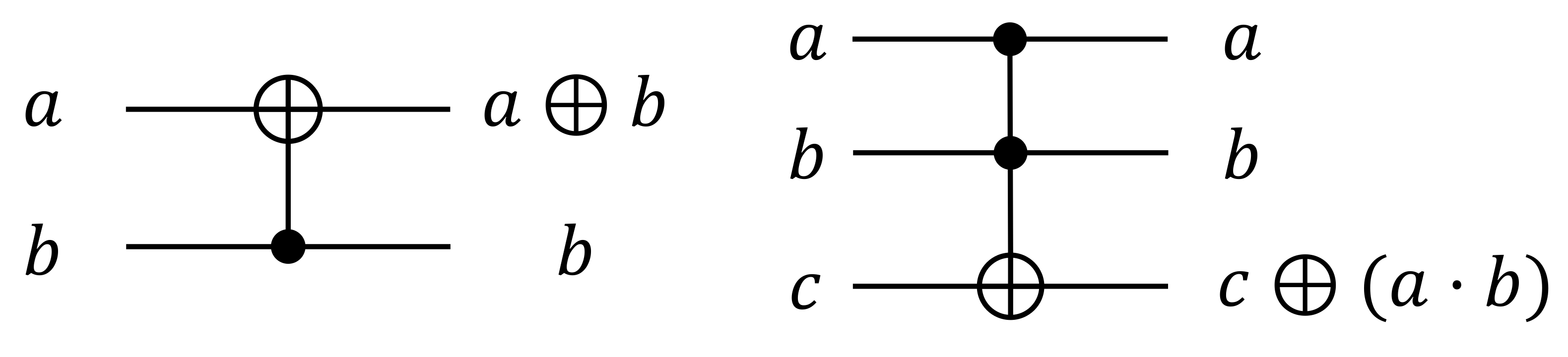
2.3. Quantum Implementations and Algorithms
2.3.1. Quantum Gates
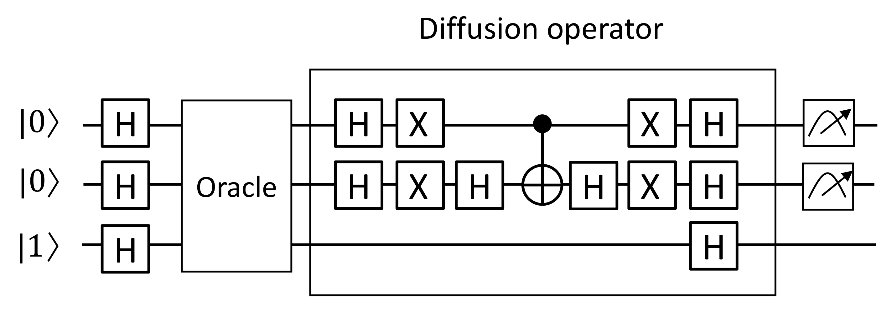
2.3.2. Grover Search Algorithm
2.3.3. Previous Quantum Implementations
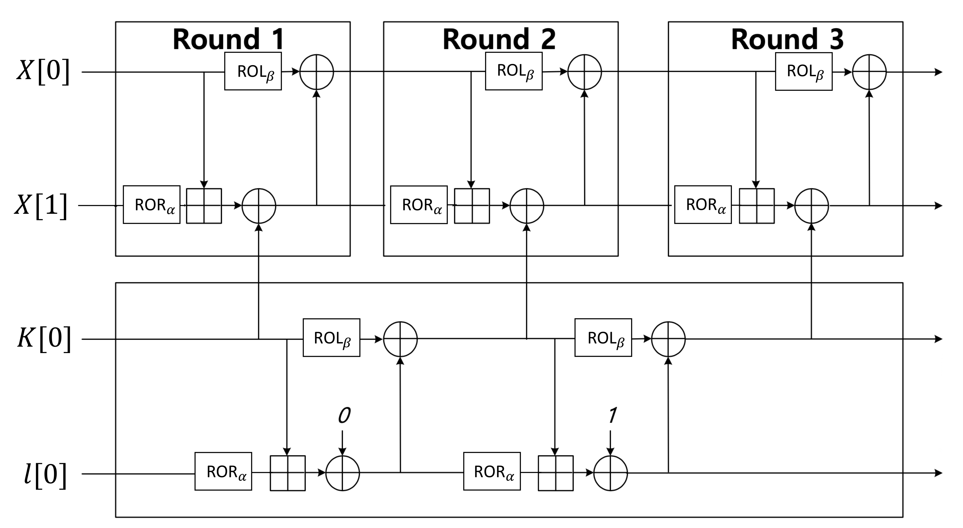
3. Proposed Method
3.1. HIGHT
3.1.1. Key Schedule
| Algorithm 1 Generate of HIGHT. |
| Input: |
| Output: |
| 1: CNOT() |
| 2: return |
| Algorithm 2i-th key schedule of HIGHT. |
| Input:, K |
| Output:K |
| 1: for to 7 do |
| 2: Generate |
| 3: ADD() |
| 4: Use in round function |
| 5: Reverse: ADD() |
| 6: end for |
| 7: for to 7 do |
| 8: Generate |
| 9: ADD() |
| 10: Use in round function |
| 11: Reverse: ADD() |
| 12: end for |
| 13: return |
3.1.2. Round Function
| Algorithm 3 Initial conversion of HIGHT. |
| Input: |
| Output: |
| 1: |
| 2: ADD() |
| 3: CNOT() |
| 4: ADD() |
| 5: CNOT() |
| 6: return |
| Algorithm 4 Round function of HIGHT. |
| Input: Round i, |
| Output: |
| 1: First, operation: |
| 2: |
| 3: CNOT() |
| 4: ADD() |
| 5: CNOT() (reverse) |
| 6: _reverse |
| 7: Second operation: |
| 8: |
| 9: ADD() |
| 10: CNOT() |
| 11: ADD() (reverse) |
| 12: _reverse |
| 13: Third operation: |
| 14: |
| 15: CNOT() |
| 16: ADD() |
| 17: CNOT() (reverse) |
| 18: _reverse |
| 19: Fourth operation: |
| 20: |
| 21: ADD() |
| 22: CNOT() |
| 23: ADD() (reverse) |
| 24: _reverse |
| 25: Last operation: |
| 26: |
| 27: return |
| Algorithm 5 of HIGHT. |
| Input: |
| Output: |
| 1: CNOT(, CNOT( |
| 2: CNOT(, CNOT( |
| 3: CNOT(, CNOT( |
| 4: |
| 5: CNOT( |
| 6: |
| 7: CNOT( |
| 8: |
| 9: CNOT(, CNOT( |
| 10: |
| 11: CNOT(, CNOT( |
| 12: |
| 13: CNOT( |
| 14: |
| 15: CNOT(, CNOT( |
| 16: CNOT(, CNOT( |
| 17: |
| 18: CNOT(, CNOT( |
| 19: CNOT(, CNOT( |
| 20: |
| 21: return |
| Algorithm 6 of HIGHT. |
| Input:X |
| Output: |
| 1: CNOT(, CNOT( |
| 2: |
| 3: CNOT(, CNOT( |
| 4: |
| 5: CNOT(, CNOT( |
| 6: |
| 7: CNOT(, CNOT( |
| 8: |
| 9:b CNOT(, CNOT( |
| 10: |
| 11: CNOT(, CNOT( |
| 12: CNOT(, CNOT( |
| 13: CNOT(, CNOT( |
| 14: |
| 15: CNOT(, CNOT( |
| 16: CNOT(, CNOT( |
| 17: |
| 18: CNOT(, CNOT( |
| 19: CNOT(, CNOT( |
| 20: |
| 21: return |
3.2. CHAM
3.2.1. Key Schedule
| Algorithm 7 key schedule of CHAM. |
| Input: |
| Output: |
| 1: CNOT(, CNOT( |
| 2: CNOT(, CNOT( |
| 3: CNOT(, CNOT( |
| 4: CNOT(, CNOT( |
| 5: for to 5 do |
| 6: CNOT( |
| 7: end for |
| 8: CNOT( |
| 9: CNOT( |
| 10: CNOT( |
| 11: for to 6 do |
| 12: CNOT( |
| 13: end for |
| 14: return |
| Algorithm 8 key schedule of CHAM. |
| Input: |
| Output: |
| 1: CNOT( temp, CNOT( temp |
| 2: CNOT( temp, CNOT( temp |
| 3: CNOT( temp, CNOT( temp |
| 4: CNOT(, CNOT( |
| 5: CNOT(, CNOT( |
| 6: |
| 7: CNOT(, CNOT( |
| 8: CNOT(, CNOT( |
| 9: |
| 10: CNOT(, CNOT( |
| 11: CNOT(, CNOT( |
| 12: |
| 13: CNOT(, CNOT( |
| 14: CNOT(, CNOT( |
| 15: |
| 16: CNOT(, CNOT( |
| 17: CNOT(, CNOT( |
| 18: |
| 19: CNOT(, CNOT( |
| 20: CNOT(, CNOT( |
| 21: |
| 22: CNOT(, CNOT( |
| 23: |
| 24: CNOT(temp, CNOT(temp |
| 25: |
| 26: CNOT(temp |
| 27: |
| 28: return |
3.2.2. Round Function
| Algorithm 9 Round function of CHAM. |
| Input:, Round i |
| Output: |
| 1: if i is odd then |
| 2: |
| 3: CNOT) |
| 4: X gate |
| 5: ADD) |
| 6: CNOT) (reverse) |
| 7: (reverse) |
| 8: |
| 9: |
| 10: else |
| 11: |
| 12: CNOT) |
| 13: X gate) |
| 14: ADD) |
| 15: CNOT) (reverse) |
| 16: (reverse) |
| 17: |
| 18: |
| 19: end if |
| 20: return } |
3.3. LEA
3.3.1. Key Schedule
| Algorithm 10i-th key schedule of LEA-128. |
| Input:, or |
| Output: |
| 1: ADD |
| 2: |
| 3: ADD |
| 4: |
| 5: ADD |
| 6: |
| 7: ADD |
| 8: |
| 9: return |
3.3.2. Round Function
| Algorithm 11 Round function of LEA-128. |
| Input:, , Round i |
| Output: |
| 1: CNOT |
| 2: CNOT |
| 3: ADD |
| 4: CNOT (reverse) |
| 5: |
| 6: CNOT |
| 7: CNOT |
| 8: ADD |
| 9: CNOT (reverse) |
| 10: |
| 11: CNOT |
| 12: CNOT |
| 13: ADD |
| 14: CNOT (reverse) |
| 15: |
| 16: |
| 17: return |
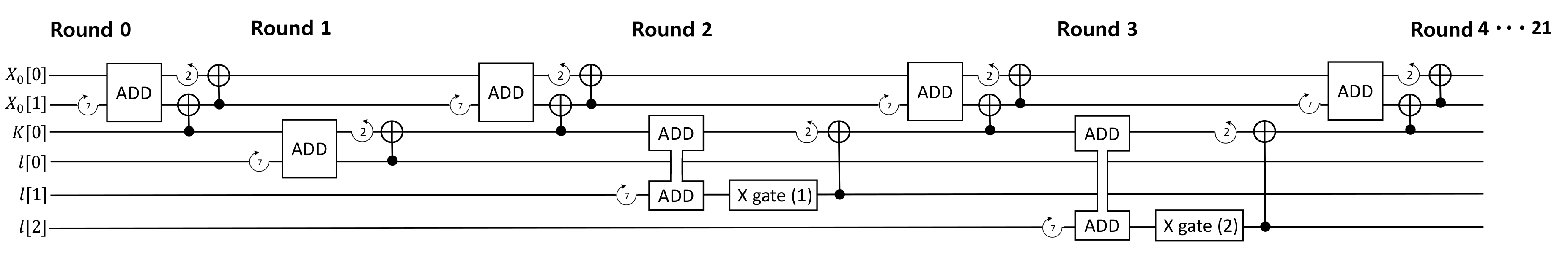
3.4. SPECK
3.4.1. Key Schedule
| Algorithm 12 RK[i] key schedule of SPECK. |
| Input: |
| Output: |
| 1: |
| 2: ADD() |
| 3: X gate() |
| 4: |
| 5: CNOT() |
| 6:) |
| 7: return |
3.4.2. Round Function
| Algorithm 13 Round function of SPECK. |
| Input:X, , Round i |
| Output: |
| 1: |
| 2: ADD() |
| 3: CNOT() |
| 4: |
| 5: CNOT() |
| 6: return |
4. Evaluation
4.1. Cost of Quantum Gates
4.2. Korean Block Ciphers in Quantum Gates
4.2.1. Case 1: 64-Bit Plaintext & 128-Bit Key
4.2.2. Case 2: 128-Bit Plaintext & 128-Bit Key
4.2.3. Case 3: 128-Bit Plaintext & 256-Bit Key
4.2.4. CASE 4: Addition of LEA and HIGHT
4.3. Software-Oriented and Hardware-Oriented Block Ciphers
4.4. SPN and ARX Based Block Ciphers
5. Conclusions
Author Contributions
Funding
Conflicts of Interest
References
- Atzori, L.; Iera, A.; Morabito, G. The Internet of Things: A survey. Comput. Netw. 2010, 54, 2787–2805. [Google Scholar] [CrossRef]
- Biryukov, A.; Perrin, L.P. State of the Art in Lightweight Symmetric Cryptography; Technical Report 2017/511, Cryptology ePrint Archive; University of Luxembourg: Luxembourg, 2017. [Google Scholar]
- Hankerson, D.; Menezes, A.J.; Vanstone, S. Guide to Elliptic Curve Cryptography; Springer Science & Business Media: Berlin/Heidelberg, Germany, 2006. [Google Scholar]
- Shor, P.W. Algorithms for quantum computation: Discrete logarithms and factoring. In Proceedings of the 35th IEEE Annual Symposium on Foundations of Computer Science, Santa Fe, NM, USA, 20–22 November 1994; pp. 124–134. [Google Scholar]
- Grover, L.K. A fast quantum mechanical algorithm for database search. In Proceedings of the Twenty-Eighth Annual ACM Symposium on Theory of Computing, Philadelphia, PA, USA, 22–24 May 1996; pp. 212–219. [Google Scholar]
- Grassl, M.; Langenberg, B.; Roetteler, M.; Steinwandt, R. Applying Grover’s algorithm to AES: Quantum resource estimates. In Post-Quantum Cryptography; Springer: Berlin/Heidelberg, Germany, 2016; pp. 29–43. [Google Scholar]
- Langenberg, B.; Pham, H.; Steinwandt, R. Reducing the Cost of Implementing AES as a Quantum Circuit; Technical Report 2019/854, Cryptology ePrint Archive; University of Luxembourg: Luxembourg, 2019. [Google Scholar]
- Jaques, S.; Naehrig, M.; Roetteler, M.; Virdia, F. Implementing Grover oracles for quantum key search on AES and LowMC. In Proceedings of the Annual International Conference on the Theory and Applications of Cryptographic Techniques, Zagreb, Croatia, 10–14 May 2020; Springer: Berlin/Heidelberg, Germany, 2020; pp. 280–310. [Google Scholar]
- Anand, R.; Maitra, A.; Mukhopadhyay, S. Grover on SIMON. arXiv 2020, arXiv:2004.10686. [Google Scholar] [CrossRef]
- Beaulieu, R.; Shors, D.; Smith, J.; Treatman-Clark, S.; Weeks, B.; Wingers, L. The SIMON and SPECK Families of Lightweight Block Ciphers. IACR Cryptol. ePrint Arch. 2013, 2013, 404–449. [Google Scholar]
- Hong, D.; Sung, J.; Hong, S.; Lim, J.; Lee, S.; Koo, B.S.; Lee, C.; Chang, D.; Lee, J.; Jeong, K.; et al. HIGHT: A new block cipher suitable for low-resource device. In Proceedings of the International Workshop on Cryptographic Hardware and Embedded Systems, Yokohama, Japan, 10–13 October 2006; Springer: Berlin/Heidelberg, Germany, 2006; pp. 46–59. [Google Scholar]
- Koo, B.; Roh, D.; Kim, H.; Jung, Y.; Lee, D.G.; Kwon, D. CHAM: A Family of Lightweight Block Ciphers for Resource-Constrained Devices. In Proceedings of the International Conference on Information Security and Cryptology (ICISC’17), Seoul, Korea, 29 November–1 December 2017; Springer: Cham, Switzerland, 2017. [Google Scholar]
- Roh, D.; Koo, B.; Jung, Y.; Jeong, I.W.; Lee, D.G.; Kwon, D.; Kim, W.H. Revised Version of Block Cipher CHAM. In Proceedings of the International Conference on Information Security and Cryptology, Seoul, Korea, 4–6 December 2019; Springer: Cham, Switzerland, 2019; pp. 1–19. [Google Scholar]
- Hong, D.; Lee, J.K.; Kim, D.C.; Kwon, D.; Ryu, K.H.; Lee, D.G. LEA: A 128-bit block cipher for fast encryption on common processors. In Proceedings of the International Workshop on Information Security Applications, Jeju Island, Korea, 19–21 August 2013; Springer: Cham, Switzerland, 2013; pp. 3–27. [Google Scholar]
- Cuccaro, S.A.; Draper, T.G.; Kutin, S.A.; Moulton, D.P. A new quantum ripple-carry addition circuit. arXiv 2004, arXiv:quant-ph/0410184. [Google Scholar]
- Draper, T.G. Addition on a quantum computer. arXiv 2000, arXiv:quant-ph/0008033. [Google Scholar]
- Draper, T.G.; Kutin, S.A.; Rains, E.M.; Svore, K.M. A logarithmic-depth quantum carry-lookahead adder. arXiv 2004, arXiv:quant-ph/0406142. [Google Scholar]
- Vedral, V.; Barenco, A.; Ekert, A. Quantum networks for elementary arithmetic operations. Phys. Rev. A 1996, 54, 147. [Google Scholar] [CrossRef] [PubMed]
- Daemen, J.; Rijmen, V. AES Proposal: Rijndael; NIST AES Competition; Springer: Berlin/Heidelberg, Germany, 1999; pp. 1–45. [Google Scholar]
- Langenberg, B.; Pham, H.; Steinwandt, R. Reducing the Cost of Implementing the Advanced Encryption Standard as a Quantum Circuit. IEEE Trans. Quantum Eng. 2020, 1, 1–12. [Google Scholar]
- Almazrooie, M.; Samsudin, A.; Abdullah, R.; Mutter, K.N. Quantum reversible circuit of AES-128. Quantum Inf. Process. 2018, 17, 112–177. [Google Scholar] [CrossRef]


| Notation | Meaning |
|---|---|
| K | Initial keywords |
| Round key | |
| ⊕ | XOR operation |
| ⊞ | Modular addition operation |
| ROL | Rotation left operation (i-bit) |
| ROR | Rotation right operation (i-bit) |
| Cipher | Block Size (Bits) | Key Size (Bits) | Word Size (Bits) | Keywords | Rounds |
|---|---|---|---|---|---|
| HIGHT | 64 | 128 | 8 | 16 | 32 |
| Cipher | Block Size (bits) | Key Size (bits) | Word Size (Bbits) | Keywords | Rounds |
|---|---|---|---|---|---|
| CHAM-64/128 | 64 | 128 | 16 | 8 | 80 |
| CHAM-128/128 | 128 | 128 | 32 | 4 | 80 |
| CHAM-128/256 | 128 | 256 | 32 | 8 | 96 |
| Cipher | Block Size (bits) | Key Size (bits) | Word Size (bits) | Keywords | Rounds |
|---|---|---|---|---|---|
| LEA-128 | 128 | 128 | 32 | 4 | 24 |
| LEA-192 | 128 | 192 | 32 | 6 | 28 |
| LEA-256 | 128 | 256 | 32 | 8 | 32 |
| Block Size (bits) | Key Size (bits) | Word Size (bits) | Keywords | Rounds |
|---|---|---|---|---|
| 32 | 64 | 16 | 4 | 22 |
| 48 | 72, 96 | 24 | 3, 4 | 22, 23 |
| 64 | 96, 128 | 32 | 3, 4 | 26, 27 |
| 96 | 96, 144 | 48 | 2, 3 | 28, 29 |
| 128 | 128, 192, 256 | 64 | 2, 3, 4 | 32, 33, 34 |
| Block Cipher | Plaintext (bit) | Key (bit) | Qubits Used | Toffoli Gates | CNOT Gates | X Gates |
|---|---|---|---|---|---|---|
| CHAM | 64 | 128 | 196 | 2400 | 12,285 | 240 |
| 128 | 128 | 268 | 4960 | 26,885 | 240 | |
| 128 | 256 | 396 | 5952 | 32,277 | 304 | |
| HIGHT | 64 | 128 | 201 | 6272 | 20,523 | 4 |
| LEA | 128 | 128 | 385 | 10,416 | 28,080 | 68 |
| 128 | 192 | 513 | 15,624 | 39,816 | 100 | |
| 128 | 256 | 641 | 17,856 | 45,504 | 130 |
| Plaintext (bit) | Key (bit) | Qubits Used | Toffoli Gates | CNOT Gates | X Gates | ||||
|---|---|---|---|---|---|---|---|---|---|
| SPECK | SIMON [9] | SPECK | SIMON [9] | SPECK | SIMON [9] | SPECK | SIMON [9] | ||
| 32 | 64 | 97 | 96 | 1290 | 512 | 3706 | 2816 | 42 | 448 |
| 48 | 72 | 121 | 120 | 1982 | 864 | 5606 | 3312 | 42 | 792 |
| 48 | 96 | 145 | 144 | 2074 | 864 | 5866 | 4800 | 45 | 768 |
| 64 | 96 | 161 | 160 | 3162 | 1344 | 8890 | 5184 | 54 | 1248 |
| 64 | 128 | 193 | 192 | 3286 | 1408 | 9238 | 7396 | 57 | 1216 |
| 96 | 96 | 193 | 192 | 5172 | 2496 | 14,436 | 9792 | 60 | 2400 |
| 96 | 144 | 241 | 240 | 5360 | 2592 | 14,960 | 10,080 | 64 | 2448 |
| 128 | 128 | 257 | 256 | 7942 | 4352 | 22,086 | 17,152 | 75 | 4224 |
| 128 | 192 | 321 | 320 | 8192 | 4416 | 22,784 | 17,472 | 80 | 4224 |
| 128 | 256 | 385 | 384 | 8444 | 4608 | 23,484 | 26,624 | 81 | 4352 |
© 2020 by the authors. Licensee MDPI, Basel, Switzerland. This article is an open access article distributed under the terms and conditions of the Creative Commons Attribution (CC BY) license (http://creativecommons.org/licenses/by/4.0/).
Share and Cite
Jang, K.; Choi, S.; Kwon, H.; Kim, H.; Park, J.; Seo, H. Grover on Korean Block Ciphers. Appl. Sci. 2020, 10, 6407. https://doi.org/10.3390/app10186407
Jang K, Choi S, Kwon H, Kim H, Park J, Seo H. Grover on Korean Block Ciphers. Applied Sciences. 2020; 10(18):6407. https://doi.org/10.3390/app10186407
Chicago/Turabian StyleJang, Kyoungbae, Seungju Choi, Hyeokdong Kwon, Hyunji Kim, Jaehoon Park, and Hwajeong Seo. 2020. "Grover on Korean Block Ciphers" Applied Sciences 10, no. 18: 6407. https://doi.org/10.3390/app10186407
APA StyleJang, K., Choi, S., Kwon, H., Kim, H., Park, J., & Seo, H. (2020). Grover on Korean Block Ciphers. Applied Sciences, 10(18), 6407. https://doi.org/10.3390/app10186407