Abstract
A numerical investigation of the propulsion performance and hydrodynamic characters of the full-active flapping foil under time-varying freestream is conducted. The finite volume method is used to calculate the unsteady Reynolds averaged Navier–Stokes by commercial Computational Fluid Dynamics (CFD) software Fluent. A mesh of two-dimensional (2D) NACA0012 foil with the Reynolds number Re = 42,000 is used in all simulations. We first investigate the propulsion performance of the flapping foil in the parameter space of reduced frequency and pitching amplitude at a uniform flow velocity. We define the time-varying freestream as a superposition of steady flow and sinusoidal pulsating flow. Then, we study the influence of time-varying flow velocity on the propulsion performance of flapping foil and note that the influence of the time-varying flow is time dependent. For one period, we find that the oscillating amplitude and the oscillating frequency coefficient of the time-varying flow have a significant influence on the propulsion performance of the flapping foil. The influence of the time-varying flow is related to the motion parameters (reduced frequency and pitching amplitude) of the flapping foil. The larger the motion parameters, the more significant the impact of propulsion performance of the flapping foil. For multiple periods, we note that the time-varying freestream has little effect on the propulsion performance of the full-active flapping foil at different pitching amplitudes and reduced frequency. In summary, we conclude that the time-varying incoming flow has little effect on the flapping propulsion performance for multiple periods. We can simplify the time-varying flow to a steady flow field to a certain extent for numerical simulation.
1. Introduction
Exploring the ocean requires a variety of marine observation equipment. In particular, the marine mobile vehicle provides new means for the ocean’s development and utilization, which significantly expands the human ability to explore, understand, and exploit the ocean. Underwater propulsion technology is one of the critical technologies of the marine mobile vehicle, which directly affects the maneuverability, operability, and endurance of vehicles. Compared with the traditional propeller, the propulsion system based on flapping foil has high stability, high efficiency, excellent maneuverability, and environmental friendliness [1,2,3]. As a result of so many advantages, it is necessary to understand the hydrodynamic performance of the propulsion system of flapping foil fully and deeply. Analyzing the impact of different parameters on the flapping foil’s propulsion performance and trying to improve its propulsion performance is of great significance for revealing the propulsion mechanism and popularizing applications.
The fluid–structure interaction between the flapping foil and flow field is complicated and unsteady [4,5]. In recent decades, many researchers have explored the propulsion mechanism of flapping foil and the effects of multiple factors on the propulsion performance through natural observation, numerical simulation, and experimental study [6,7,8]. Previous studies have found that factors such as the motion amplitude and reduced frequency [9], motion trajectory [10], St (Strouhal number) [11], pivot location [12], phase difference between heaving and pitching motions [13], shape and flexibility of the foil [14,15] can directly affect the hydrodynamic performance of the flapping foil. The reduced frequency and the amplitude of heaving and pitching motion are the main factors affecting the flapping flow field structure [9]. Koochesfahani and Manoochehr [16] study the hydrodynamic performance and wake vortex of the pure pitching flapping foil at a small amplitude through the tank experiment. The results show that the wake vortex structure can be effectively controlled by controlling the reduced frequency, pitching amplitude, and motion trajectory, which can significantly affect the flapping foil’s thrust. Ashraf [17] and Dewey [18] analyze the effect of the reduced frequency on the propulsion performance of full-active flapping foil. They find that there is a critical value for the reduced frequency. When the reduced frequency is less than the critical value, the mean thrust coefficient increases monotonously. However, when the reduced frequency is higher than the critical value, the propulsion performance of flapping foil decreases significantly. The influencing mechanism of heaving and pitching motion amplitude is similar to the reduced frequency [7,17]. The thickness, chord length, curvature, and flexibility also affect the foil’s hydrodynamic performance [11,19,20]. Besides, some researchers study the influence of non-sinusoidal motion trajectories on the propulsion performance of flapping foil and intend to improve it [21,22,23,24,25].
According to the above research, most researchers assume the freestream as uniform and steady when studying the hydrodynamic performance of flapping foil. In the marine environment, especially when approaching the surface and floor of the sea, the flow field is usually non-uniform and time-varying due to the seabed topography or the wind and waves. The conclusions based on the above assumption may not reflect the hydrodynamic performance of flapping foil under real conditions. The numerical simulation results obtained by simplifying the flow to a uniform flow may not be accurate enough. Therefore, it is of great practical significance to analyze the influence of non-uniform and time-varying freestream velocity on the propulsion performance of the flapping foil. We noticed a few studies on the influence of non-uniform and time-varying flow velocity on the propulsion performance of the flapping foil. In contrast, the influence of non-uniform flow velocity on the flapping foil’s energy harvesting performance has been investigated systematically [26,27,28]. Kinsey and Dumas [29] study the effect of small amplitude disturbances of freestream on the hydrodynamic performance of flapping foil and point out that the influence on the energy harvesting performance of the flapping foil is almost negligible. Zhu [26] and Cho [27] analyze the effect of linear shear flow on the energy harvesting performance of two-dimensional flapping foil. They find that the flow field under a low shear rate can slightly improve the flapping foil’s performance, while the energy harvesting efficiency of flapping foil reduces sharply when the shear rate is large enough. Ma [30] examines the effect of time-varying flow velocity on the energy harvesting performance of two-dimensional flapping foil. The study also points out that flapping foil’s hydrodynamic performance is greatly affected by the time-varying flow rate in one cycle. When calculating the mean performance in eight periods, the time-varying freestream velocity has little effect on the flapping foil’s energy harvesting performance. In addition, other researchers have found that the free surface and waves also have an important impact on the hydrodynamic performance of the flapping foil. Silva [31] investigates the possibility of extracting energy from gravity waves by a two-dimensional flapping foil. He points out that the marine propulsion of the flapping foil can absorb energy form sea waves and improve the propulsion performance when the design parameters are correctly maintained. Filippas and Belibassakis [32] analyze the hydrodynamic performance of the flapping foil under free surface and in waves by unsteady boundary element method. They note that significant efficiency of the flapping foil can be obtained under optimal wave conditions. Xu [33] investigates the propulsion of a flapping foil in heading wave through the velocity potential theory and indicates that the frequency difference between the foil and waves has a significant effect on the hydrodynamic performance of the flapping foil.
Referring to the non-uniform flow on the energy harvesting performance of flapping foil, we notice that both the small amplitude shear flow and the time-varying flow velocity have little effect. Therefore, we can infer that the influence of the non-uniform flow with a small amplitude on the propulsion performance of the flapping foil should also be weak. To verify the above inference, we analyze the effect of time-varying flow velocity on the flapping foil’s propulsion performance through numerical simulation. In this paper, the kinematic model of full-active flapping foil under time-varying flow velocity is established. The finite volume method (FVM) is used to calculate the unsteady Reynolds averaged Navier–Stokes (URANS) by commercial CFD software Fluent version 19.1. We first investigate the propulsion performance of flapping foil in the parameter space of reduced frequency and pitching amplitude at a uniform flow velocity. Then, we study the influence of time-varying flow velocity on the propulsion performance of flapping foil. Moreover, the effect mechanism of time-varying flow velocity on the hydrodynamic performance of flapping foil is explained by analyzing the evolutions of vortex topology, flow velocity, and pressure distribution around the foil.
2. Problem Description and Methodology
2.1. Problem Description
Referring to Zhu [26] and Cho [27], we note that the shear flow is mainly affected by the seafloor topography, while the marine vehicles propelled by flapping foil are mostly used in the vast ocean, the influence of the terrain on the flow field can be ignored. Therefore, we only discuss the effect of time-varying flow velocity on the propulsion performance of active flapping wings in this paper. The sketch of full-active flapping foil under time-varying freestream velocity is illustrated in Figure 1. The foil has two degrees of freedom, which can only translate in the vertical direction and rotate around the pivot, other degrees of freedom are strictly prohibited. The heaving and pitching motions of the flapping foil are fully prescribed and defined as a sinusoidal motion. A two-dimensional NACA0012 foil is used in this paper, and are defined as the chord length and the thickness of the foil, the foil’s pivot is located at one third of chord.
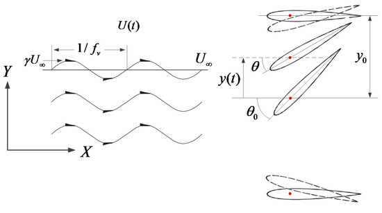
Figure 1.
Sketch of full-active flapping foil under time-varying freestream velocity.
The heaving and pitching motion of the full-active flapping foil are defined as:
where and are defined as the heaving and pitching amplitudes, respectively. is the motion frequency, is the non-dimensional coefficient of motion frequency, named reduced frequency, . is the phase different between the heaving and pitching motions, . Referring to the assumptions of time-varying flow velocity made by Gharali [34] and Chen [35], the time-varying freestream in this paper is considered as a superposition of steady flow and sinusoidal pulsating flow. Therefore, the time-varying flow is defined as:
where is the constant term of flow, is the pulsating term of flow. and are defined as the oscillating amplitude and oscillating frequency of the time-varying flow. is defined as the oscillating frequency coefficient of the time-varying flow, . The instantaneous thrust coefficient, instantaneous lift coefficient and instantaneous moment coefficient of full-active flapping foil are expressed as:
where , and are defined as the thrust, lift and moment. is the fluid density. The instantaneous input power and propulsion power are defined as:
where is the heaving velocity, is the pitching velocity. The mean input power coefficient and mean propulsion power coefficient are expressed as:
where is defined as the period of the heaving and pitching motion of the flapping foil, . The propulsion efficiency of the full-active flapping foil is defined as:
2.2. Numerical Methods and Validation
Based on the sliding mesh technology, the computational domain and boundary conditions for 2D flapping foil is illustrated in Figure 2. We use PointWise software to mesh the 2D flapping foil. The entire computation domain is , the inner grid diameter is . The inlet, outlet, upper wall and low wall are divided into 25 equal parts, the sliding interface is divided into 120 equal parts, and the foil wall is divided into 600 equal parts. The height of the first layer near the foil is set to , and grows 30 layers at a rate of 1.1, which ensures . The flow distribution in the viscous sub-layer and transition layer of the foil surface is solved by using the Navier-Stokes (NS) equation discretely. We use a sliding interface to divide the simulation domain into the inner grid and outer grid. The rigid movement of the inner grid can ensure that the inner grid is undeformed and improves the calculation accuracy near the foil. Referring to Equations (1) and (2), we program the user defined functions (UDFs) to control the heaving and pitching motions of the inner grid. With the motion of the inner grid, the outer grid adjusts adaptively. The inlet condition for time-varying flow velocity is controlled by the UDFs according to Equation (3). The outlet condition is a pressure outlet, and the upper and lower wall is symmetry. The Reynolds number is , the Sparat–Allmaras turbulence model is used, and the SIMPLE algorithm is selected for pressure–velocity coupling calculation. The discrete methods of gradient and pressure are least squares cell-based and second-order discrete, respectively. Momentum, turbulent flow energy and turbulent dissipation rate are all selected in second-order upwind. Time discretization is set second-order implicit format. The convergence condition of velocity and continuity is . The judgment condition for the periodic simulation is that the change rate of the mean value of the instantaneous thrust coefficient is less than 1%. According to different simulation parameters of flapping foil, a stable periodic solution of the flapping foil can be obtained after 10 cycles.
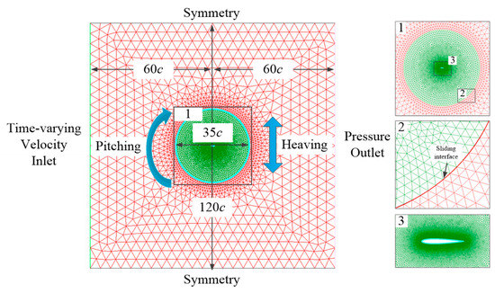
Figure 2.
Computational domain and boundary conditions for two-dimensional (2D) flapping foil.
To verify the simulation strategy, the grid, time independence and validation are studied in our previous research [10]. We simulated four grid and time-steps levels. The comparison of the mean value of thrust coefficient, lift coefficient and propulsion efficiency corresponding to the different grid and time-steps levels is shown in Table 1. In order to ensure the accuracy and calculation efficiency, we chose the mesh and time step as 80,000 cells and 800 time-steps for all simulation cases. We also validated the current strategy against the classic literature [36] under the same conditions, as shown in Figure 3, and found that the result agrees well with the Kinsey and Dumas, which confirm the simulation strategy of this paper is credible and accurate.

Table 1.
Grid and time independence.
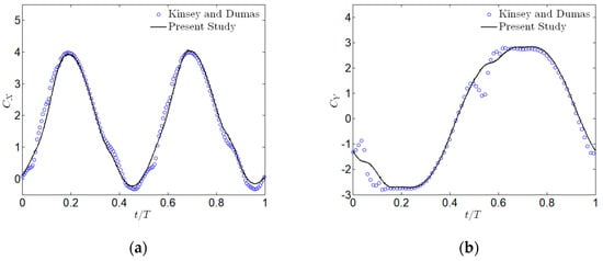
Figure 3.
Comparison of results by the present study and Kinsey and Dumas for , , , (a) thrust coefficient and (b) lift coefficient.
3. Results and Discussions
In this paper, we first analyze the propulsion performance of the full-active flapping foil in the parameter space of reduced frequency and pitching amplitude at a uniform freestream. Then, we study the effects of the oscillating amplitude, oscillating frequency coefficient, and simulation time of the time-varying freestream on the propulsion performance of the full-active flapping foil. Finally, based on the evolution of the instantaneous thrust coefficient, wake vortex, velocity and pressure near the foil, we reveal the mechanism of the time-varying freestream on the hydrodynamic performance of the full-active flapping foil. The range of the oscillating amplitude and frequency of the time-varying freestream is selected based on the literature [30]. The other physical parameters of the flapping foil refer to the physical parameters of wave glider [10]. The main parameters are shown in Table 2.
Table 2.
Main characteristics for computations.
3.1. The Propulsion Performance of Flapping Foil at Uniform Freestream
The amplitude and frequency of the heaving and pitching motions are the main factors affecting the hydrodynamic performance of the full-active flapping foil at uniform freestream [9,29,37]. We first illustrate the contour of the mean propulsion power coefficient of the flapping foil in the parameter space of reduced frequency and pitching amplitude, as shown in Figure 4. We note that the reduced frequency and pitching amplitude have a significant effect on the mean propulsion power coefficient. Further, we observe that the effect of the pitching amplitude on the propulsion performance is related to the reduced frequency. When , the mean propulsion power coefficient of the flapping foil increases first and then decreases with the variation of the pitching amplitude. The optimal pitching amplitude appears at the middle of the pitching amplitude range, where the mean propulsion power coefficient of the flapping foil reaches the maximum value. When and , the maximum values of the mean propulsion power coefficients are 0.51 and 2.32, respectively, and the corresponding optimal pitching amplitudes are both . According to Figure 4, we further notice that with the reduction in the reduced frequency, the optimal pitching amplitude of the flapping foil is decreased gradually. When , the optimal pitching amplitude is , and when , the optimal pitching amplitude is reduced to . Furthermore, we realize that when , the mean propulsion power coefficient of the flapping foil decreases monotonically with the variation of the pitching amplitude. When , the mean propulsion power coefficients corresponding to and are 0.027 and 0.32, respectively.
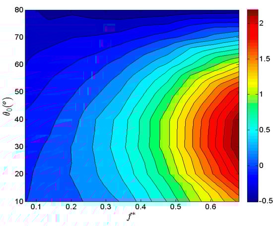
Figure 4.
The mean output power coefficient contour on the parametric space of reduced frequency and pitching amplitude.
The contour of the propulsion efficiency of the full-active flapping foil on the parametric space of reduced frequency and pitching amplitude is illustrated in Figure 5. The dark blue region of the Figure 5 indicates that the mean propulsion power coefficient and propulsion efficiency in this range are less than zero. According to Figure 5, we reveal that with the variation of the pitching amplitude, the propulsion efficiency decreases monotonically. When , the propulsion efficiencies of the flapping foil corresponding to and are 48.1% and 14.1%, respectively. When , the propulsion efficiencies of the flapping foil corresponding to and are 4.7% and 0.5%, respectively. According to Figure 5, we also note that with the variation of the reduced frequency, the propulsion efficiency increases monotonically. When , the propulsion efficiencies of the flapping foil corresponding to and are 6.4% and 19.3%, respectively.
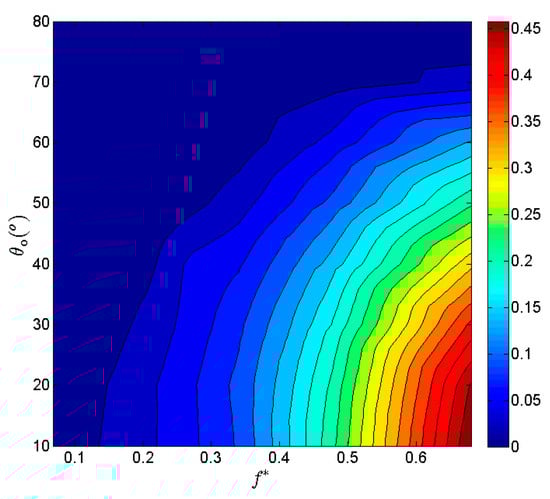
Figure 5.
The propulsion efficiency contour on the parametric space of reduced frequency and pitching amplitude.
Based on the above research, we conclude that when the reduced frequency is small, the smaller pitching amplitude can improve the propulsion performance of the full-active flapping foil. When the reduced frequency is large, the proper pitching amplitude can reach the best propulsion performance. Hover et al. [7] studied the influence mechanism of the leading-edge vortex on the hydrodynamic performance of the flapping foil. They reveal that the proper pitching amplitude is beneficial to the generated of the leading-edge vortex and reverse Karman vortex, which can improve the propulsion performance of the flapping foil. Meanwhile, we also note that when the pitching amplitude is large enough, the mean propulsion power coefficient is less than zero. Thus, the flapping foil cannot generate thrust in this condition.
3.2. The Influence of the Time Varying Freestream
In the previous section, we discuss the propulsion performance of the full-active flapping foil at uniform freestream and analyze the reduced frequency and pitching amplitude on the foil. Based on the above study, the oscillating amplitude and oscillating frequency coefficient of the time-varying freestream on the hydrodynamic performance of the flapping foil is investigated in this section. First, we analyze the effect of the time-varying flow velocity on the flapping foil in one period, which is the period of the heaving and pitching motion of the flapping foil. Then, we study the influence of the time-varying freestream on the mean propulsion of the foil at a different period. Finally, we recalculate the mean propulsion power coefficient of the flapping foil over 10 periods and analyze the influence of the time-varying flow on the propulsion performance of the flapping foil.
3.2.1. The Effect of the Time-Varying Flow in One Period
According to Figure 4, we choose different parameters of reduced frequency (/) and pitching amplitude (//) to study the influence of oscillating amplitude and oscillating frequency coefficient of the time-varying flow on the propulsion performance of the full-active flapping foil. The evolution of the mean propulsion power coefficient of the flapping foil with different oscillating amplitude and oscillating frequency coefficient is shown in Figure 6. We notice that the oscillating frequency coefficient of the time-varying flow has a significant effect on the mean propulsion power coefficient. In particular, the effect of the oscillating frequency coefficient on the flapping foil is related to the pitching amplitude and reduced frequency of the flapping foil. When the motion parameters are large, the time-varying flow has a more significant effect on the flapping performance of the flapping foil. When , the maximum change rate of the mean propulsion power coefficient caused by the oscillating frequency coefficient for and is 9.8% and 13%, respectively. When , the maximum change rate of the mean propulsion power coefficient caused by the oscillating frequency coefficient for and is 4.3% and 5.3%, respectively. Besides, we also found that when the vibration coefficient, the impact of the oscillating frequency coefficient on the propulsion performance of active flapping is significantly reduced. We further notice that when the oscillating frequency coefficient , the impact of the time-varying flow on the mean propulsion performance of the flapping foil is significantly reduced, as shown in Figure 6. Ma [30] and Chen [35] have obtained similar conclusions when studying the effect of time-varying freestream on the energy harvesting performance of the full-active flapping foil.
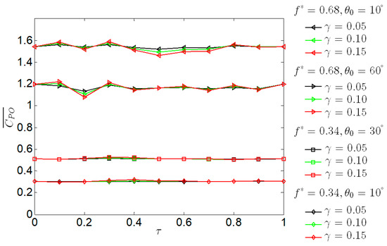
Figure 6.
The evolution of the mean propulsion power coefficient with different oscillating amplitude and oscillating frequency coefficient for one period.
Referring to Figure 6, we also notice that the oscillating amplitude of the time-varying flow also affects the hydrodynamic performance of the full-active flapping foil. With the increase in the oscillating amplitude, the variation amplitude of the mean propulsion power coefficient of the flapping foil caused by the oscillating frequency coefficient increases proportionally, but the variation tendency does not change. When and , the maximum change rate of the mean propulsion power coefficient caused by the oscillating frequency coefficient for and are 1.5% and 5.3%, respectively. Since the oscillating amplitude does not affect the tendency of the time-varying flow on the propulsion performance of the full-active flapping foil, in order to simplify the simulation calculation, the oscillating amplitudes in the subsequent calculations are all fixed values, .
3.2.2. The Effect of the Time-Varying Flow in Different Periods
To observe the effect of the time-varying flow on the propulsion performance of the flapping foil in different periods, the variation of the mean propulsion power coefficient in different periods and oscillating frequency coefficient is illustrated in Figure 7. When , and , the numerical simulation obtains a stable periodic solution after 10 cycles. Therefore, we choose the data within 10–20 cycles for comparison. According to Figure 7, the oscillating frequency coefficient of the time-varying flow has an apparent regularity for the impact of the mean propulsion power coefficient of the flapping foil. When and , with the variation of the oscillating frequency coefficient and simulation period, the mean propulsion power coefficient is almost unchanged. According to Equation (3), when the reduced frequency is an integer multiple of the oscillating frequency coefficient of the time-varying flow, the average flow velocity of the time-varying flow in one cycle is equal to the constant term . Therefore, the time-varying freestream has no significant effect on the hydrodynamic performance of the full-active flapping foil. When the relationship between the oscillating frequency coefficient of the time-varying freestream and the reduced frequency is not an integer multiple, with the variation of the simulation period, the oscillating frequency coefficient directly affects the mean propulsion power coefficient of the full-active flapping foil. When , the mean propulsion power coefficient of the flapping foil fluctuates significantly, and when , the mean propulsion power coefficient is almost unchanged with the variation of the period, as shown in Figure 7. The influence of the oscillating frequency coefficient on the flapping foil can also be found in Figure 6. The reason of the above phenomenon is that the oscillating frequency coefficient of the time-varying flow affects the average flow velocity in one cycle. Especially when , the change of the average flow velocity in different periods is more prominent. The average flow velocity leads to differences in the hydrodynamic performance of the flapping foil in different periods.
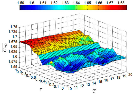
Figure 7.
The variation of the mean propulsion power coefficient in different periods and oscillating frequency coefficients for , .
The effect of the time-varying flow on the propulsion performance of the flapping foil for and is described above. Then, we analyze the influence of the time-varying flow on the flapping foil with the variation of the period under different motion parameters (reduced frequency and pitching amplitude). The evolution of the mean propulsion power coefficient for different reduced frequency and pitching amplitude at and is shown in Figure 8. We note that with the increase in the pitching amplitude of the flapping foil, the variation amplitude of the mean propulsion power coefficient of the flapping foil caused by the oscillating frequency coefficient increases gradually. When and , the maximum change rates of the mean propulsion power coefficient caused by the time-varying freestream for ,, and are 2.3%, 3.7%, 6.8% and 23.6%, respectively. When and , the maximum change rates of the mean propulsion power coefficient caused by the time-varying freestream for , , and are 2%, 2.1%, 4.1% and 21.4%, respectively. Furthermore, we reveal that with the variation of the reduced frequency, the maximum change rates of the mean propulsion power coefficient caused by the time-varying freestream increase gradually. When and , the maximum change rates of the mean propulsion power coefficient caused by the time-varying freestream for , 0.45 and 0.68 are 3.4%, 6.2% and 6.8%, respectively. When and , the maximum change rates of the mean propulsion power coefficient caused by the time-varying freestream for , 0.45 and 0.68 are 2.4%, 3.9% and 4.1%, respectively.
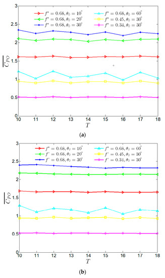
Figure 8.
The evolution of the mean propulsion power coefficient for different reduced frequency and pitching amplitude, (a) , (b) .
3.2.3. The Effect of the Time-Varying Flow in Multiple Periods
In the previous section, the influence of the time-varying flow on the propulsion performance of the full-active flapping foil in different periods is investigated. We note that the simulation time can affect the hydrodynamic performance of the flapping foil under the action of the time-varying freestream. The oscillating amplitude and frequency determine the average velocity of the time-varying flow in different periods, which affects the propulsion performance of the foil. Therefore, we infer that the average velocity of the time-varying flow under different oscillating amplitude and oscillating frequency coefficient in multiple periods will tend to the constant velocity. Thus, with the extension of simulation time, the effect of the time-varying flow on the flapping foil will gradually weaken. Kinsey [29] and Ma [30] also found a similar phenomenon when studying the effect of time-varying flow on the energy harvesting performance of the full-active flapping foil. The average value of the propulsion power coefficient in 10 cycles with the variation of the oscillating frequency coefficient is shown in Figure 9. Referring to Figure 8, we know that a larger pitching amplitude and reduced frequency can increase the maximum change rate of the mean propulsion power coefficient of the flapping foil affected by the time-varying flow. Referring to Figure 9, when and , the maximum change rate of the flapping foil is only 4.8%. Therefore, we conclude that the time-varying freestream has little effect on the propulsion performance of the full-active flapping foil at different pitching amplitude and reduced frequency. When we calculate the hydrodynamic performance of the flapping foil by using numerical simulation, we can simplify the time-varying freestream to the steady flow.
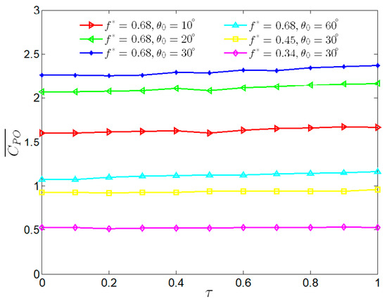
Figure 9.
The evolution of the mean propulsion power coefficient with the variation of the oscillating frequency coefficient.
3.3. The Mechanism of the Time Varying Freestream
In the previous section, we analyze the influence of the time-varying flow on the flapping foil. Then, we study the effects of the time-varying flow on the evolution of instantaneous thrust coefficients, vortex topology, velocity field, and the pressure distribution near the foil, and further explain the effect mechanism of the time-varying flow. Referring to Figure 8, we notice that when and , the oscillating frequency coefficient of the time-varying flow has a significant effect on the mean propulsion performance of the flapping. Therefore, we analyze the evolution of the instantaneous thrust coefficient under these motion parameters. The evolution of the instantaneous thrust coefficient and freestream velocity over three periods is shown in Figure 10. We notice that the instantaneous thrust coefficient has two peaks and troughs within one period. The peaks and troughs are the maximum instantaneous resistance and thrust of the flapping foil. Comparing the evolution of instantaneous thrust coefficient and time-varying flow velocity at different oscillating frequencies of the time-varying flow, we find that there is a correlation between the instantaneous velocity and the variation of the instantaneous thrust coefficient of the flapping foil. When , the instantaneous thrust coefficients for , 0.2 and 0.8 are 1.9, 2.15 and 2.25, respectively. The corresponding instantaneous velocity are 2.5 m/s, 2.65 m/s and 2.87 m/s, respectively. When , the instantaneous thrust coefficients for , 0.2 and 0.8 are 1.9, 2.3 and 2.4, respectively. The corresponding instantaneous velocities are 2.5 m/s, 2.65 m/s and 2.87 m/s, respectively. In the vicinity of the peak, the instantaneous resistance of the flapping foil gradually increases with the increase in the instantaneous velocity. When , the instantaneous thrust coefficients for , and are −5.41, −5.85 and −5.75, respectively. The corresponding instantaneous velocities are 2.79 m/s, 2.41 m/s and 2.39 m/s, respectively. We can also note that the instantaneous thrust of the flapping foil gradually increases with the increase in the instantaneous velocity in the vicinity of the trough.
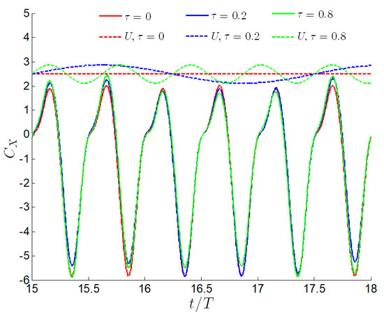
Figure 10.
The evolution of the instantaneous thrust coefficient and freestream velocity over three periods for , .
In order to further explain the mechanism of the influence of time-varying flow on the flapping foil, the three snapshots of the vorticity contours and the corresponding velocity contours for different oscillating frequency coefficient (, 0.2 and 0.8) are shown in Figure 11. According to Figure 10, we choose the moment when the instantaneous thrust coefficient reaches the peak. We notice that the vortexes near the foil for the three oscillating frequency coefficient is basically the same, which shows that the time-varying flow does not significantly change the vortex topology of the flapping foil. However, we find differences between the velocity distribution near the foil for different oscillating frequencies. Referring to Figure 10, we note that with the variation of the oscillating frequency coefficient, the instantaneous velocities increases. Comparing Figure 11a–c, we find that as the instantaneous velocity increases, the velocity close to the lower surface of the foil gradually increases. According to the Bernoulli equation, the pressure gradient drops as the velocity increases. Therefore, comparing with and , a more significant negative pressure region on the lower surface of the foil is generated, which leads to an increase in the resistance and reduces the propulsion performance of the flapping foil. Referring to Figure 11, the pressure distribution of the flapping foil at , 0.2 and 0.8 is shown in Figure 12. We note that the pressure distributions on the upper surface of the foil for different oscillating frequencies are almost the same. However, there is a clear difference in the pressure distributions on the lower surface of the foil for different oscillating frequencies. The instantaneous velocity of the lower surface of the foil for is more significant than and , as shown in Figure 11. The strength of the corresponding negative pressure region on the lower surface of the foil for is greater than and , which increases the resistance of the flapping foil, as shown in Figure 10.
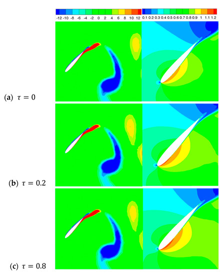
Figure 11.
The snapshots of the vorticity contours and velocity contours for , , , (a) , (b) , (c) .
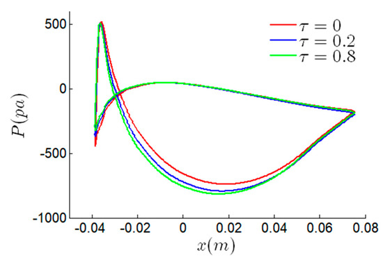
Figure 12.
The pressure distribution of the flapping foil at different oscillating frequency coefficient for , ,
According to Equation (3), we note that the oscillating frequency coefficient of the time-varying flow determines the fluctuation of the instantaneous velocity. When , the instantaneous velocity for , and are 2.79 m/s, 2.41 m/s and 2.39 m/s, respectively, as shown in Figure 10. The three snapshots of the vorticity contours and the corresponding velocity contours for at different simulation times are shown in Figure 13. The corresponding pressure distribution of the flapping foil is shown in Figure 14. Due to the little fluctuation range of the time-varying flow, the vortex topology of the flapping foil at a different time is slightly different. However, the velocity distribution near the foil can also be observed. The velocity of the leading edge of the flapping foil at is slightly greater than and , as shown in Figure 13. According to the Bernoulli equation, the intensity of the negative pressure region generated by the leading edge of the lower surface of the flapping foil at is greater than and , as shown in Figure 14. The strong negative pressure region at the leading edge of the flapping foil increases the thrust. Referring to Figure 10, we note that the maximum value of the instantaneous thrust coefficient at . We can conclude that the time-varying flow affects the pressure distribution of the flapping foil. However, its impact on the propulsion performance of the flapping foil is also related to the relative position between the negative pressure area and the foil.
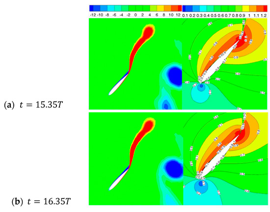
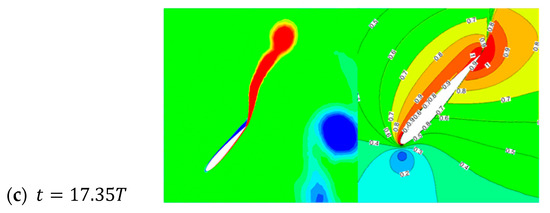
Figure 13.
The snapshots of the vorticity contours and pressure contours for , , , (a) , (b) , (c) .
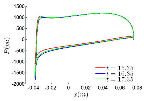
Figure 14.
The pressure distribution of the flapping foil at different moments for , , .
4. Conclusions
In this paper, the propulsion performance and hydrodynamic characteristics of the full-active flapping foil in the time-varying freestream are systematically investigated via two-dimensional URANS and the finite volume method. We define the time-varying freestream as a superposition of steady flow and sinusoidal pulsating flow. Through numerical simulation results, we summarize several conclusions as follows: We first analyze the propulsion performance of the flapping foil at uniform freestream, and note that when the reduced frequency is small, the smaller pitching amplitude can obtain the higher propulsion performance of the full-active flapping foil. When the reduced frequency is large, the mean propulsion power coefficient increases first and then decreases with the variation of the pitching amplitude. We also reveal that with the increase in the pitching amplitude, the propulsion efficiency of the foil decreases monotonically. Then, we examine the influence of the time-varying freestream on the propulsion performance of the flapping foil for various oscillating amplitude and oscillating frequency coefficient, and find that the influence of the time-varying flow is time dependent. For one period, we notice that the oscillating amplitude does not affect the tendency of the time-varying flow on the propulsion performance of the flapping foil. With the increase in the oscillating amplitude, the variation amplitude of the mean propulsion power coefficient caused by the time-varying flow increases proportionally. We reveal that the effect of the time-varying flow on the flapping foil depends on the range of the oscillating frequency coefficient. When , the mean propulsion power coefficient of the flapping foil fluctuates significantly, and when , the mean propulsion power coefficient is almost unchanged with the variation of the period. In particular, when the oscillation frequency of the time-varying flow is an integer multiple of the reduced frequency, the time-varying flow has almost no effect on the flapping foil. Otherwise, we also note that the effect of the time-varying flow is related to the motion parameters of the flapping foil. The larger the motion parameters, the more significant the impact of propulsion performance of the flapping foil. For multiple periods, we note that the time-varying freestream has little effect on the propulsion performance of the full-active flapping foil at different pitching amplitude and reduced frequency.
In conclusion, we reveal that the time-varying incoming flow has little effect on the flapping propulsion performance for multiple periods. Therefore, we can simplify the time-varying flow to a steady flow field to a certain extent for numerical simulation. Meanwhile, we also realize that only the small oscillating amplitude of the time-varying flow is considered in this paper. The impact of large oscillating amplitude has not been discussed. Otherwise, the hydrological conditions in the marine environment are more complicated; their impact on the propulsion performance of the full-active flapping foil cannot be predicted accurately.
Author Contributions
Conceptualization, Z.Q.; formal analysis, Z.Q. and L.J.; funding acquisition, L.J. and J.Z; investigation, Z.Q., Y.Q. and J.S.; methodology, Z.Q.; validation, Z.Q. and L.J.; writing—original draft, Z.Q.; writing—review and editing, J.Z. All authors have read and agreed to the published version of the manuscript.
Funding
This study was funded by the Natural Science Foundation of Tianjin (grant number 18JCYBJC24000), the Key Laboratory of Submarine Geosciences, MNR (grant number KLSG1907) and the National Key Research and Development Project (grant number 2017YFC0305900).
Acknowledgments
The authors would like to thank the anonymous reviewers for their constructive comments and suggestions.
Conflicts of Interest
The authors declare no conflict of interest.
References
- Bøckmann, E.; Steen, S.; Myrhaug, D. Performance of a Ship Powered Purely by Renewable Energy. In Proceedings of the International Conference on Offshore Mechanics and Arctic Engineering, San Francisco, CA, USA, 8–13 June 2014. [Google Scholar]
- Floc’H, F.; Phoemsapthawee, S.; Laurens, J.M.; Leroux, J.-B. Porpoising foil as a propulsion system. Ocean Eng. 2012, 39, 53–61. [Google Scholar] [CrossRef]
- Qi, Z.; Zou, B.; Lu, H.; Shi, J.; Li, G.; Qin, Y.; Zhai, J. Numerical Investigation of the Semi-Active Flapping Foil of the Wave Glider. J. Mar. Sci. Eng. 2019, 8, 13. [Google Scholar] [CrossRef]
- Lee, J.; Choi, H.; Kim, H.Y. A scaling law for the lift of hovering insects. J. Fluid Mech. 2015, 782, 479–490. [Google Scholar] [CrossRef][Green Version]
- Shyy, W.; Aono, H.; Chimakurthi, S.; Trizila, P.; Kang, C.-K.; Cesnik, C.; Liu, H. Recent progress in flapping wing aerodynamics and aeroelasticity. Prog. Aerosp. Sci. 2010, 46, 284–327. [Google Scholar] [CrossRef]
- Wu, T.Y.-T. Swimming of a Waving Plate. J. Fluid Mech. 1961, 10, 321–344. [Google Scholar] [CrossRef]
- Anderson, J.M.; Streitlien, K.; Barrett, D.S.; Triantafyllou, M.S. Oscillating foils of high propulsive efficiency. J. Fluid Mech. 1998, 360, 41–72. [Google Scholar] [CrossRef]
- Triantafyllou, G.S.; Triantafyllou, M.S.; Grosenbaugh, M.A. Optimal Thrust Development in Oscillating Foils with Application to Fish Propulsion. J. Fluids Struct. 1993, 7, 205–224. [Google Scholar] [CrossRef]
- Schouveiler, L.; Hover, F.S.; Triantafyllou, M.S. Performance of flapping foil propulsion. J. Fluids Struct. 2005, 20, 949–959. [Google Scholar] [CrossRef]
- Qi, Z.; Zhai, J.; Li, G.; Peng, J. Effects of non-sinusoidal pitching motion on the propulsion performance of an oscillating foil. PLoS ONE 2019, 14, e218832. [Google Scholar] [CrossRef] [PubMed]
- Zhang, D.; Pan, G.; Chao, L.; Zhang, Y. Effects of Reynolds number and thickness on an undulatory self-propelled foil. Phys. Fluids 2018, 30, 71902. [Google Scholar] [CrossRef]
- Mackowski, A.W.; Williamson, C.H.K. Effect of pivot location and passive heave on propulsion from a pitching airfoil. Phys. Rev. Fluids 2017, 2, 35–40. [Google Scholar] [CrossRef]
- Young, J.; Lai, J.C.S. On the Aerodynamic Forces of a Plunging Airfoil. J. Mech. Sci. Technol. 2007, 21, 1388–1397. [Google Scholar] [CrossRef]
- Ashraf, M.A.; Young, J.; Lai, J.C.S. Reynolds number, thickness and camber effects on flapping airfoil propulsion. J. Fluids Struct. 2011, 27, 145–160. [Google Scholar] [CrossRef]
- Hoke, C.M.; Young, J.; Lai, J.C.S. Effects of time-varying camber deformation on flapping foil propulsion and power extraction. J. Fluids Struct. 2015, 56, 152–176. [Google Scholar] [CrossRef]
- Koochesfahani, M.M. Vortical patterns in the wake of an oscillating airfoil. AIAA J. 1989, 27, 1200–1205. [Google Scholar] [CrossRef]
- Ashraf, I.; Agrawal, A.; Khan, M.H.; Srivastava, A.; Sharma, A. Thrust generation and wake structure for flow across a pitching airfoil at low Reynolds number. Sadhana 2015, 40, 2367–2379. [Google Scholar] [CrossRef]
- Dewey, P.A.; Boschitsch, B.M.; Moored, K.W.; Stone, H.A.; Smits, A.J. Scaling laws for the thrust production of flexible pitching panels. J. Fluid Mech. 2013, 732, 29–46. [Google Scholar] [CrossRef]
- Rozhdestvensky, K.V.; Ryzhov, V.A. Aerohydrodynamics of flapping-wing propulsors. Prog. Aerosp. Sci. 2003, 39, 585–633. [Google Scholar] [CrossRef]
- Cebeci, T.; Platzer, M.; Chen, H.; Chang, K.-C.; Shao, J.P. Analysis of Low Speed Unsteady Airfoil Flows; Springer: Berlin/Heidelberg, Germany, 2004. [Google Scholar]
- Wang, W.; Yan, Y.; Tian, F. Numerical study on hydrodynamics for a non-sinusoidal forced oscillating hydrofoil based on an immersed boundary method. Ocean Eng. 2018, 147, 606–620. [Google Scholar] [CrossRef]
- Xiao, Q.; Liao, W. Numerical study of asymmetric effect on a pitching foil. Int. J. Mod. Phys. 2011, 20, 1663–1680. [Google Scholar] [CrossRef]
- Yang, S.; Liu, C.; Wu, J. Effect of motion trajectory on the aerodynamic performance of a flapping airfoil. J. Fluids Struct. 2017, 75, 213–232. [Google Scholar] [CrossRef]
- Esfahani, J.A.; Barati, E.; Karbasian, H.R. Fluid structures of flapping airfoil with elliptical motion trajectory. Comput. Fluids 2015, 108, 142–155. [Google Scholar] [CrossRef]
- Xiao, Q.; Liao, W. Numerical investigation of angle of attack profile on propulsion performance of an oscillating foil. Comput. Fluids 2010, 39, 1366–1380. [Google Scholar] [CrossRef]
- Zhu, Q. Energy harvesting by a purely passive flapping foil from shear flows. J. Fluids Struct. 2012, 34, 157–169. [Google Scholar] [CrossRef]
- Cho, H.; Zhu, Q. Performance of a flapping foil flow energy harvester in shear flows. J. Fluids Struct. 2014, 51, 199–210. [Google Scholar] [CrossRef]
- Yu, M.; Wang, B.; Wang, Z.J.; Farokhi, S. Evolution of vortex structures over flapping foils in shear flows and its impact on aerodynamic performance. J. Fluids Struct. 2018, 76, 116–134. [Google Scholar] [CrossRef]
- Kinsey, T.; Dumas, G. Computational Fluid Dynamics Analysis of a Hydrokinetic Turbine Based on Oscillating Hydrofoils. J. Fluids Eng. 2012, 134, 21104. [Google Scholar] [CrossRef]
- Ma, P.; Wang, Y.; Xie, Y.; Huo, Z. Effects of time-varying freestream velocity on energy harvesting using an oscillating foil. Ocean Eng. 2018, 153, 353–362. [Google Scholar] [CrossRef]
- De Silva, L.W.A.; Yamaguchi, H. Numerical study on active wave devouring propulsion. J. Mar. Sci. Technol. 2012, 17, 261–275. [Google Scholar] [CrossRef]
- Filippas, E.S.; Belibassakis, K.A. Hydrodynamic analysis of flapping-foil thrusters operating beneath the free surface and in waves. Eng. Anal. Bound. Elem. 2014, 41, 47–59. [Google Scholar] [CrossRef]
- Xu, G.D.; Duan, W.Y.; Zhou, B.Z. Propulsion of an active flapping foil in heading waves of deep water. Eng. Anal. Bound. Elem. 2017, 84, 63–76. [Google Scholar] [CrossRef]
- Gharali, K.; Johnson, D.A. Dynamic stall simulation of a pitching airfoil under unsteady freestream velocity. J. Fluids Struct. 2013, 42, 228–244. [Google Scholar] [CrossRef]
- Chen, Y.; Zhan, J.; Wu, J.; Wu, J. A fully-activated flapping foil in wind gust: Energy harvesting performance investigation. Ocean Eng. 2017, 138, 112–122. [Google Scholar] [CrossRef]
- Kinsey, T.; Dumas, G. Parametric Study of an Oscillating Airfoil in a Power-Extraction Regime. AIAA J. 2008, 46, 1318–1330. [Google Scholar] [CrossRef]
- Read, D.A.; Hover, F.S.; Triantafyllou, M.S. Forces on oscillating foils for propulsion and maneuvering. J. Fluids Struct. 2003, 17, 163–183. [Google Scholar] [CrossRef]
© 2020 by the authors. Licensee MDPI, Basel, Switzerland. This article is an open access article distributed under the terms and conditions of the Creative Commons Attribution (CC BY) license (http://creativecommons.org/licenses/by/4.0/).